Article

Symmetric Excitons in an (001)-Based InAs/GaAs Quantum Dot Near Si Dopant for Photon-Pair Entanglement

1
State Key Laboratory for Superlattice and Microstructures, Institute of Semiconductors, Chinese Academy of Sciences, Beijing 100083, China
2
Beijing Academy of Quantum Information Sciences, Beijing 100193, China
3
Center of Materials Science and Optoelectronics Engineering, College of Materials Science and Opto-Electronic Technology, University of Chinese Academy of Sciences, Beijing 100049, China
4
Joint Laboratory of Advanced Semiconductor, Nanjing Guoke Semiconductor Co., Ltd., Nanjing 211800, China
*
Author to whom correspondence should be addressed.
Crystals 2021, 11(10), 1194; https://doi.org/10.3390/cryst11101194
Submission received: 2 August 2021 / Revised: 22 September 2021 / Accepted: 24 September 2021 / Published: 30 September 2021

Abstract

:
The sacrificed-QD-layer method can well control the indium deposition amount to grow InAs quantum dots (QDs) with isotropic geometry. Individual Si dopant above an (001)-based InAs QD proves a new method to build a local electric field to reduce fine structure splitting (FSS = X1−X2) and show D3h symmetric excitons. The lowest FSS obtained is 3.9 μeV with the lowest energy X state (LX) anticlockwise rotate from [1–10] (i.e., zero FSS will be crossed in a proper field). The lateral field projection induces a large eh separation and various FSS, LX, and emission intensity polarization. The lateral field along [1–10] breaks the X1–X2 wavefunction degeneracy for independent HH and VV cascade emissions with robust polarization correlation. With FSS ~4 μeV and T1 ~0.3 ns fastened in a distributed Bragg reflector cavity, polarization-resolved XX–X cross-correlations show fidelity ~0.55 to a maximal entangled state |HH> + |VV>. A higher fidelity and zero FSS will be obtained in the hybrid QD structure with a junction field integrated to tune the FSS and a sub-bandgap excitation to avoid influences from electrons in the barrier.

1. Introduction

Cascade emission in a semiconductor quantum dot (QD) from the biexciton state XX to the ground state G via the intermediate exciton states X ( | and | ,   ,   : electron, , : hole spin) can emit polarization-entangled photon pairs |LR > + |RL > (R (L): right (left) circular polarization). However, a real epitaxial QD with in-plane anisotropy (e.g., [1–10] and [110] on (001) plane) shows X1 and X2 ( |   ±   | ) with fine structure splitting (FSS) and horizontal (H) or vertical (V) linearly polarized two photon emission in a state |HH> + eiT1FSS/ħ|VV > (T1: time delay between XX and X photons, i.e., intrinsic X radiative lifetime Tx, Figure 1a). The FSS must be smaller than a lifetime-limited radiative linewidth 1/(2πT1) (e.g., 4.9 μeV for T1 = 134 ps fasten in a microcavity [1]) to erase decay-path information for entanglement [2,3,4]. For strain-driven (001)-based InAs QDs with a flexible wavelength (λ), 870~1600 nm [5,6,7,8], structures (e.g., strain-coupled QD bilayer [5], dot-in-barrier [6], or dot-in-well [7]) and microcavity integration, it shows FSS > 10 μeV [9,10,11,12] typically and spin scattering time Tss ~1.9 ns [2]. The FSS can be reduced by growing C3v QD on (111) surface [13,14,15,16,17] or a post-grown electric field (different Stark shifts for X1 and X2) [18,19] or stress [10,11,20,21] tuning. Due to a deviation of X1 and X2 from the main crystal axis [110] and [1–10], the erasure of FSS requires a biaxial stress (in-plane) tuning or a combination of stress (in-plane) and electric field (vertical) tuning. Besides, QD geometrical anisotropy (e.g., shape, strain or charged environment) induces light hole (lh)-heavy hole (hh) mixing (in degree β) and photon polarization mixing as the emission intensity polarization (EIP) reflects [22,23,24], which is quite correlated to the growth parameters such as growth temperature, indium deposition amount and surface migration time. For instance, in our experiments (shown elsewhere), for single InAs QDs at λ = 870 nm formed among dense small QDs at λ = 860 nm (a broad PL spectral profile) by indium migration, a little increase of indium deposition will induce a great EIP transition from a pure dipole to an ellipse and finally a circle (i.e., β ≈ 0) with QD emission intensity increasing monotonously. These parameters are well controlled in the sacrificed-QD-layer growth method we developed to obtain QDs with isotropic geometry. In this work, individual Si dopant intentionally added above a QD proves a new method to build a local electric field for electron-hole (eh) separation in the [001] axis to show D3h symmetric excitons as pyramidal (111) QDs [16,17] and reduce FSS to zero (in an as-grown sample with no fine tuning, the lowest FSS obtained is 3.9 μeV with the lowest-energy X state (LX) anticlockwise rotate from [1–10], i.e., zero FSS will be crossed in a proper field). QDs show small lh-hh mixing degree: β ≈ 0 with no doping or in a vertical electric field, and β ≈ 0.2 (close to strain-free GaAs QDs, implying no strain contribution) in an in-plane field. With FSS ~4 μeV and T1 ~0.3 ns in a distributed Bragg reflector (DBR) cavity, polarization-resolved XX–X cross-correlations reflect a fidelity F ~0.55 to the maximal entangled state |HH> +|VV>. The lateral field projection in a diverse direction shows a great eh separation for various FSS, LX and EIP. The lateral field along X2 [1–10] breaks X1–X2 wavefunction degeneracy and forbids spin flip between them to show independent HH and VV cascade emission for polarization-correlated applications. Compared to pyramidal (111) QDs or droplet epitaxial QDs with small FSS as grown, the (001) QDs with Si doping above to reduce FSS have advantages: (1) easy to grow with the growth parameters well controlled; (2) easy to integrate a microcavity (e.g., DBR, circular Bragg grating or photonic crystal) to reduce T1 and enhance QD light extraction; (3) with fewer interface defects. Compared to biaxial stress tuning or the combination of stress and electric field tuning post-grown to reduce FSS [20,21], the local field has advantages: (1) easy to realize and the electric field tuning to erase FSS can be realized by integrating a p-i-n or Shockley junction, facilitating device fabrication; (2) the local field helps to deplete neighbor defects and ‘purify’ the QD environment; (3) the hybrid QD structure can be well designed (e.g., the field magnitude and the barrier height with AlGaAs [25,26,27]) and the QD geometry is optimized independently. With a junction field integrated to tune FSS and a sub-bandgap excitation to avoid spin flip from electrons in the barrier, the hybrid QD structure has the potential to get zero FSS and a higher entanglement fidelity.

2. Materials and Methods

Dilute InAs/GaAs QDs were grown by a solid-source molecular beam epitaxy on a semi-insulating GaAs (001) substrate and located at the middle of a planar 1λ-GaAs cavity between the bottom (24.5×) and the top (4×) GaAs/Al0.9Ga0.1As DBRs with λ at 920 nm in situ calibrated to enhance light extraction. QDs were grown at a rate of 0.005 monolayer/s in As4 flux pressure of 1 × 10⁻⁶ Torr at a nominal temperature (T) 540 °C. A sacrificed QD layer was grown first to monitor island by reflection high energy electron diffraction (RHEED) and determine the proper indium deposition amount [28,29] and then evaporated at 670 °C for 15 min until the point array in RHEED pattern disappeared (the residual indium atoms were removed). After a 80 nm GaAs capping at 580 °C to flatten the surface and space a possible defect introduced in the sacrificed layer, the formal QDs were grown without substrate rotation to yield gradient indium flux and QD density along [1–10] [30,31]. As the atomic force microscope (AFM) image in Figure 1c shows, the uncapped QD has a height ~8 nm and a base diameter ~40 nm, symmetric in shape. After a 10 nm GaAs capping, a Si δ-doping layer in surface density of 1 × 108 cm−2 (i.e., individual Si atoms in a microregion) was added to compensate the background p-type impurities (e.g., carbons, that induce a dominant X+ [32,33]) for dominant X and XX emissions, followed by a 20 nm GaAs before raising T to 580 °C for the residual structure growth. See Figure 1b, the 10 nm GaAs capping built a 4-nm space (d) between the QD and the Si dopant above it, corresponding to the maximal Coulomb field of E = e / 4 π ε 0 ε r GaAs d 2 = 75   kV / cm at the QD to reduce electron (at QD top) and hole (at QD base) wavefunction overlap [34] for small FSS and higher D3h exciton symmetry, i.e., a three-fold rotation symmetry and a mirror one along the [001] axis. The local field helps to purify the QD environment from fluctuation charges of a hole defect [35] (red dot) that is at least 50 nm away from the hybrid QD structure and only induces a linewidth broadening of ~15 μeV from spectral diffusion. The influence is only from electrons near the Si dopant for tunneling and spin flip. For a Si dopant near a QD, the extra electron fills in QD with lower energy level and builds a local electric field and a Fermi level pin at QD level in favor of XX population. These electrons are depleted by filling neighbor defects to enhance the local field and show a dominant X+ and a weak XX with a strong electron tunneling (the XX population is unaffected in the sub-bandgap excitation). The 4 nm barrier (i.e., height and thickness) is flexible for design to optimize the local field and reduce tunneling [19]. Similarly, in a two-dimensional heterostructure, modulated doping to form electron gas is inserted in the AlGaAs barrier a little spaced from the interface. Since the Si atoms are randomly distributed, to build a desired vertical field, one dopant for each QD is desired. Molecular beam epitaxy is quite suitable for the control of such QD/barrier interface and the growth of such hybrid QD structure. Here, since the local field was diverse and unknown in an as-grown sample, to investigate the field dependence, no AlGaAs capping was used and a high field was evidenced from a weak XX and an electron level coupling between QD e1 and Rydberg level at Si dopant.
Single QD spectroscopy was performed by a micro-photoluminescence (μPL) setup with fiber routes and a 0.75 m grating monochromator equipped with a liquid-nitrogen cooled charge coupled device camera (spectral resolution: 50 μeV). The sample cooled in a helium-flow cryostat (T = 5 K) was cw-excited at 632.8 nm [32]. A polarization selective filtering (i.e., a half-wave plate (HWP) and a linear polarizer (LP)) suppresses a distinct fine-structure component to observe the subtle shift below the spectrometer resolution in resolution of ~2 μeV. As Figure 1d indicates, the sample strip along [1–10] was positioned as reference, the LP was fixed at 45° from [1–10] while the HWP (dash lines) rotated clockwise with angle α to select a linear polarization: α = 67.5° for that along [110] and α = 22.5° for that along [1–10]. X and XX showed FSS oscillations in the same scale and opposite signs; X+ and X showed zero FSS. The electron level coupling between QD e1 and Rydberg level at Si dopant in a high field induced FSS in X (1e1h in QD and 1e near Si dopant) and zero FSS in XX (1e2h in QD and 1e near Si dopant). The FSS of each QD was characterized to find one <7 μeV (30%) and ~4 μeV (only 10%). For as-grown sample with no fine tuning, the FFS and LX polarization (i.e., angle θ from [110]) were strongly dependent on the local field. The various FSS and LX θ can be well depicted by X1–X2 coupling [19]: in a vertical field, for anti-crossing coupling, as the field increased, the FSS first reduced to a minimum Δ and then increased; the LX θ varied slowly from ~90° (X2 along [1–10]) in a low field to 0° < θ < 90° in a medium field to get Δ and ~0° (X1 along [110]) in a much higher field; for crossing coupling with zero Δ, a fast anticlockwise rotation from [1–10] θ = −90°, equivalent to θ > 90°, occurred, as shown in Figure 2 and Figure 3; for an in-plane field, the case was opposite: clockwise rotation corresponds to a small FSS and anticlockwise rotation a large FSS, as shown in Figure 4. The EIP (i.e., angle φ from [110]) was orthogonal to the LX that reflected a stronger emission in the higher-energy X state (HX) from lh-hh mixing [22] in the local field; there was little strain contribution since a QD with no doping shows nearly isotropic emission intensity (e.g., QD29 and 30 in Figure 4). The EIP was obvious in a lateral field and disappeared in a high vertical field; its degree (i.e., β) characterized the geometrical anisotropy of QDs buried in GaAs, identical in the same sample (e.g., QD20, 27 and 28 in Figure 3 and Figure 4b with a 12 nm capping before Si dopant). Polarization-resolved XX–X cross-correlations g2XXiXj in the basis {i, j} = {H, V, R, L, D (diagonal), A (antidiagonal)} were measured by a Hanbury Brown-Twiss setup integrated on the uPL [32] in time resolution ~600 ps, including a 50:50 beamsplitter, each beam with a narrowline bandpass (NBP, <0.5 nm, OD6) to filter X or XX photons and a polarization filter (i.e., an LP and a quarter-wave plate (QWP), for H/V and D/A, only LP in different angles was used; for R/L, LP and QWP with 45° angle offset were used) before fiber collection, two avalanched Si single-photon counters and a time-to-digital converter for coincidence count histogram. Polarization correlation and entanglement fidelity F were reflected in the correlation contrasts Cij = (g2ii − g2ij)/(g2ii + g2ij) (j opposite to i), and compared to the theoretical (F, FSS) fitting curve [2,3].

3. Results and Discussion

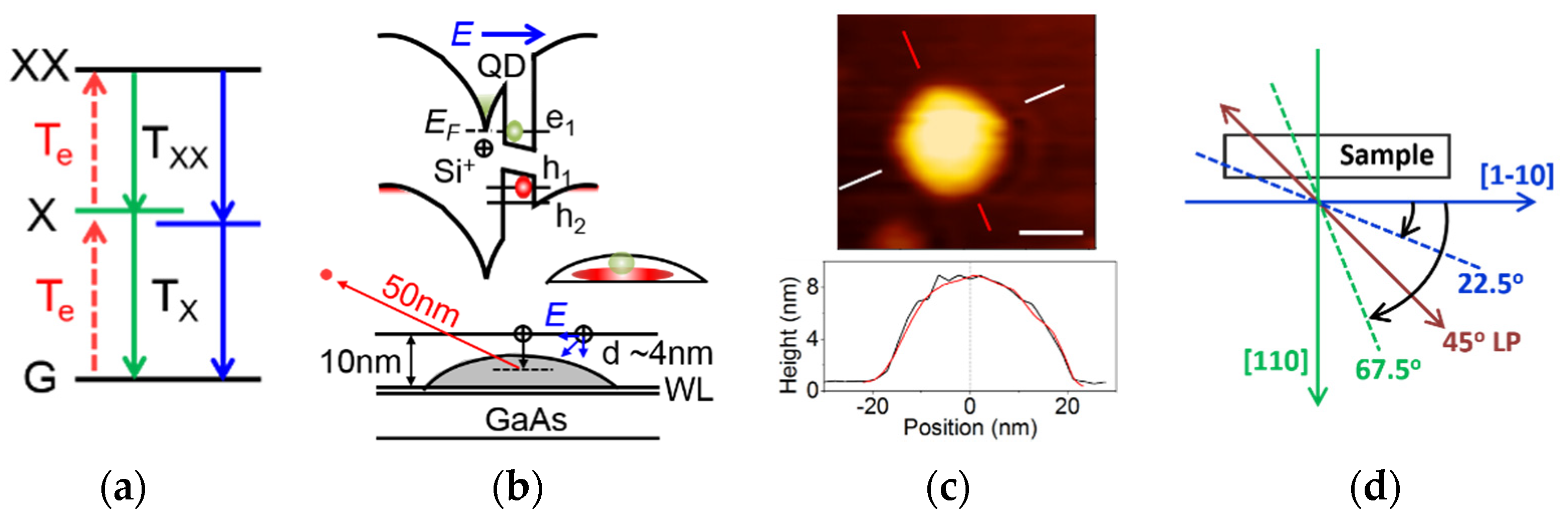
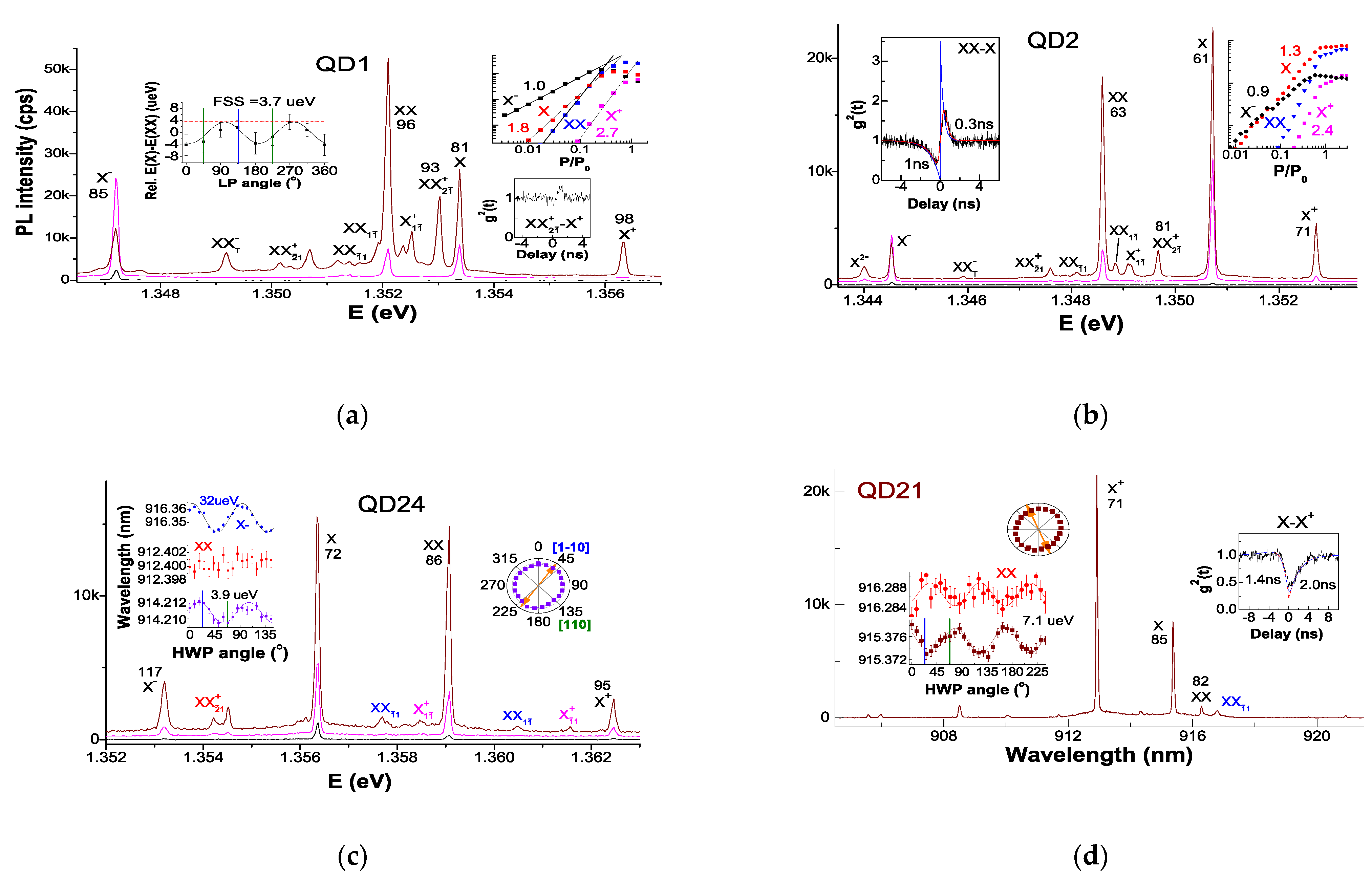
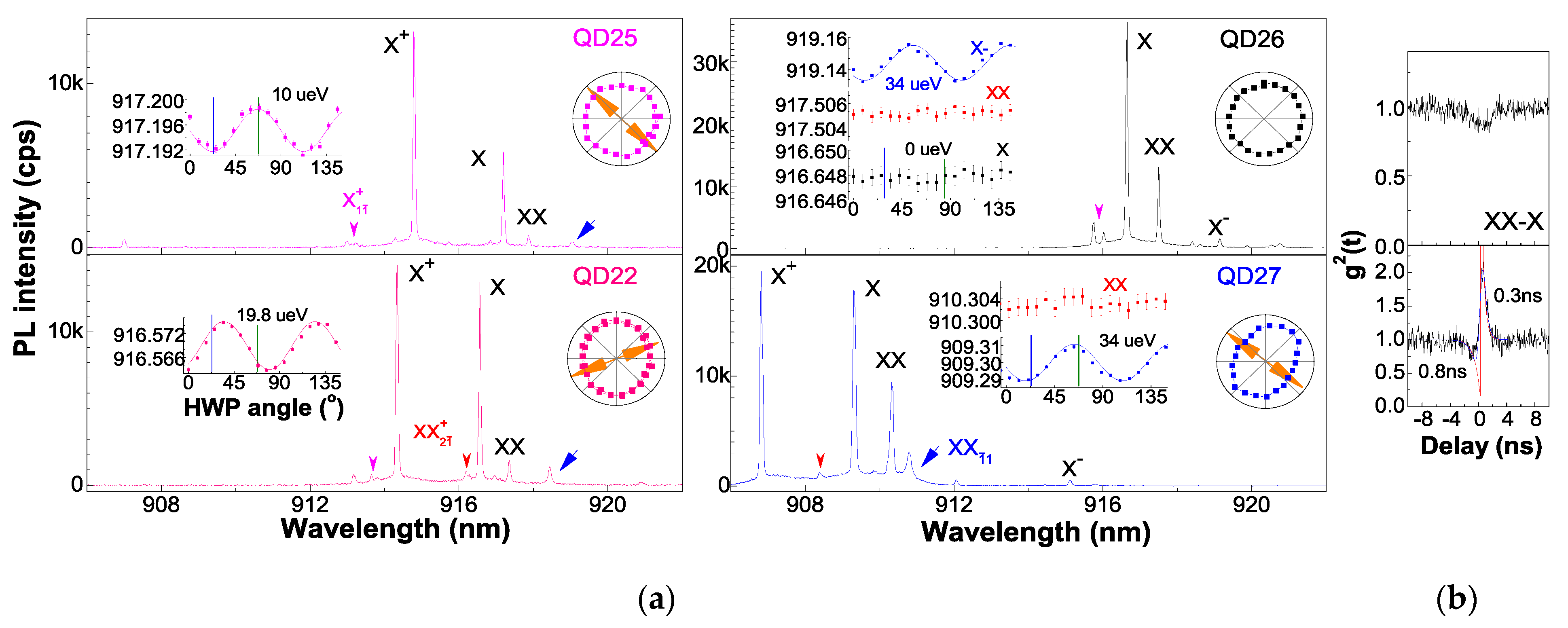
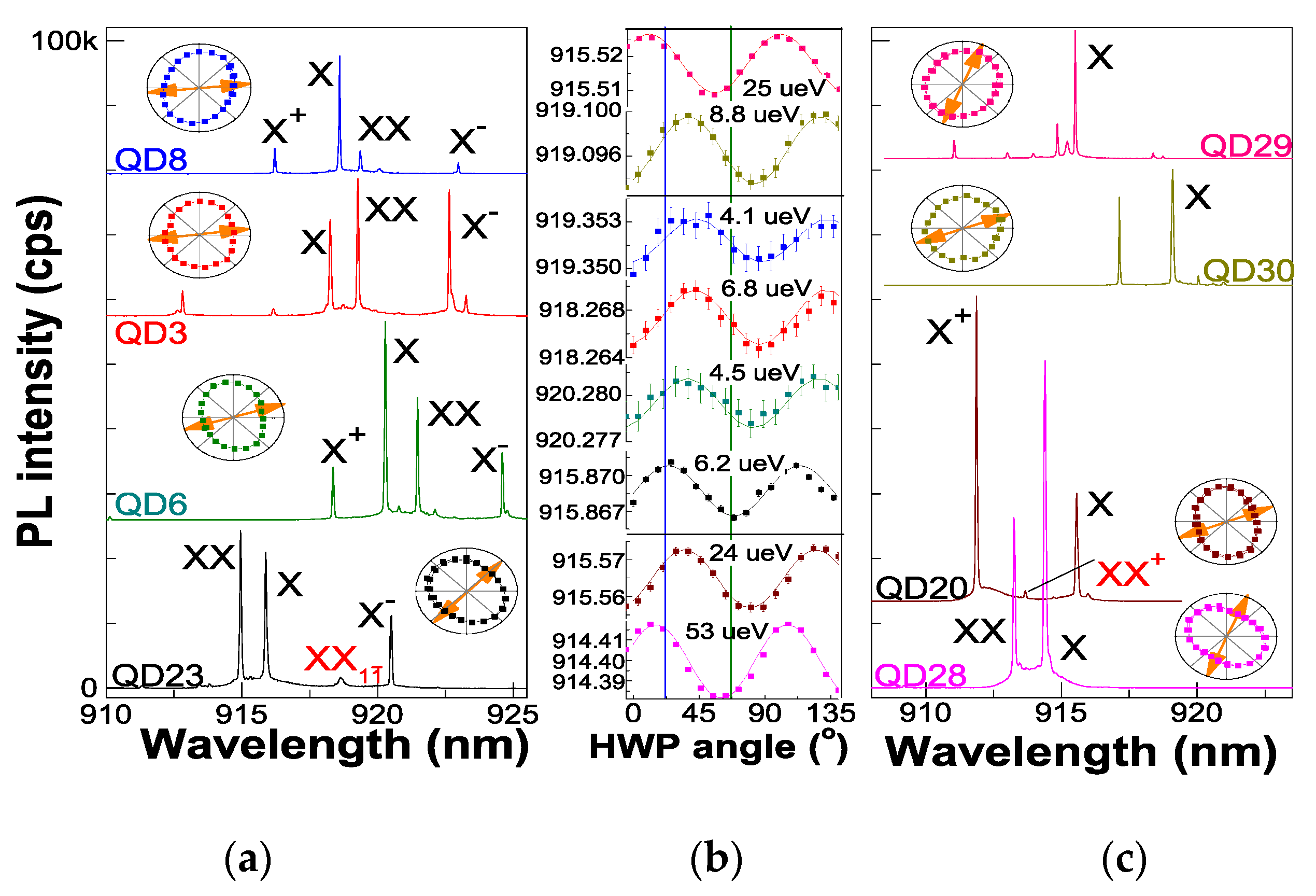
3.1. D3h Symmetric Exciton Emissions

Figure 2 presents the QDs with D3h symmetric exciton emissions in a spectral feature as pyramidal (111) QDs [16,17] from valence band mixing and lh h2 for e1-h2 transitions XX+, X+ and XX and e1-h1 ones XX 2 ¯ 1 + , Xī1+ and XXī1 (indexes mean the hole numbers in h1 (first) and h2 (second) with a bar classifying the transitions) [16,33], located around XX as a mirror. XX+ singlet built a cascade with X+ as the bunching peak in their cross-correlation reflects, weaker than before [33] due to a fast electron capture in X+ to populate XX; X+ doublet (split by Δhh ± (ΔIeh + ΔIIeh): 150 μeV in QD1 or 50 μeV in QD2) and XX doublet (split by Δhh−Δ0eh [16] of near zero); a broad XXT- (doublet split by ~Δ0eh/2 [33]) also appeared. In QD1, the three peaks in XXī1 were well depicted by D3h transition diagram (σ-polarized) while the three peaks in XX 2 ¯ 1 + with the v iii ¯ branch appearing to reflect C3v [16], the lack of a mirror symmetry; in QD2, both XX 2 ¯ 1 + and XXī1 showed one peak from D3h (z-polarized) [16]. In QD24, the higher field showed a relatively lower emission intensity and made these peaks a little far from XX that has a negative binding energy. QD5 in Supplementary Materials (SM) shows more D3h exciton emissions while the QDs in a high electric field, e.g., QD21 and QDs in Figure 3 and Figure 4a, only show e1-h2 ones, XX+ singlet located between X and XX, XX doublet split by Δhh−Δ0eh of 70 μeV and X+ doublet far from XX, from a large h1−h2 energy offset in the field. For epitaxial QDs with a less lateral confinement, the eh separation and Stark shift in the lateral direction to tune FSS requires a relatively lower electric field [36]. The appearance of the D3h symmetric excitons reflects a vertical field for eh separation along [001] for higher exciton symmetry; the FSS, varying from dot to dot, e.g., QD4 in SM with similar spectral features and a high XX as QD1 but FSS of 11 μeV, is from an in-plane field projection as a perturbation; the FSS is also reported in pyramidal QDs from composition alloy or piezoelectric potential [15]. For QD1 and QD2, the Si dopant filled two electrons in QD e1 (Fermi level pin), resulting in the first appearance of X(slope: 1.0 or 0.9) before X under weak excitation (black line), a higher slope for X (1.8 or 1.3) and an effective XX population under high excitation (wine line) in the slope of 2.4~2.7, the same as X+ (2h capture); QD1 had a higher total intensity and a relatively higher XX saturated intensity (50 kcps), reflecting a fluent electron capture due to electron level coupling by tunneling that also broadens the spectral line. The line-shape of each spectral line is a Gaussian envelope with different linewidths, broadened by 10~70 μeV after subtracting the spectrometer resolution, and tails in the lower-energy side reflecting wavefunction tunneling into the barrier, in spite of a natural radiative linewidth of a few ueV in a Lorentzian line-shape. The spectral diffusion from fluctuating charges >50 nm from a QD leads to a linewidth broadening ~15 μeV (Stark shift slope of ~50 μeV/(kV/cm) [18]); the rest broadening of 0~60 μeV is from electron tunneling and wavefunction coupling between QD e1 and Rydberg level at the Si dopant. In QD2, XX+ (linewidth: 81 μeV) with respect to X+ (71 μeV), X (61 μeV), XX (63 μeV) and X (62 μeV) reflected no electron tunneling broadening; in QD1, XX+ (93 μeV) with respect to X+ (98 μeV), X (81 μeV), XX (96 μeV) and X (85 μeV) reflected an electron tunneling broadening of ~45 μeV for XX and X+ that showed the same linewidth (similar for QD4 in SM). As a result, in QD1 and QD4, the XX population at saturation was greatly enhanced. The QDs in Figure 4a also showed the first appearance of X, a relatively higher XX and LX clockwise rotate from [1–10] related to a lateral field projection. In contrast, for QD24, the Si dopant built a strong vertical field for small FSS of 3.9 μeV in X; electron level coupling in the field induces abnormal FSS, zero in XX and 32 μeV in X and X+, a less electron tunneling broadening of ~16 μeV for XX (linewidth: 86 μeV) and X (117 μeV) after subtracting its FSS, but zero for X+ (95 μeV) after subtracting its FSS due to its greatly lower field (2h in QD and 1e at Si dopant) and the first appearance of X under weak excitation. Mostly, a QD in a vertical field with little tunneling shows a dominant X+ and a weak XX (e.g., QD21), with the same FSS for X and XX. The XX–X cross-correlation in QD2 shows an asymmetric profile, with characteristic times for the antibunching dip of 1 ns (i.e., 2Te for XX population and Te = 0.5 ns for X) and the bunching peak of T1 ~0.3 ns, i.e., intrinsic X radiative lifetime, the XX repopulation (i.e., the upper Te in Figure 1a) therefore competes with the cascade emission. The bunching peak remains if XX has tunneling (zero FSS) while it disappears if X has tunneling (zero FSS), see QD26 and QD27 in Figure 3. An asymmetric antibunching profile is shown in X–X+ cross-correlation in QD21 with the fitting times 1.4 ns reflecting slow electron capture and 2.0 ns reflecting X+ (1e2h) population. The different correlation profiles help to identify the dominant X, X+ or XX peak.

3.2. FSS Field Dependence

The FSS field dependence is illustrated in Figure 3 (QDs in a high vertical field with a dominant X+ and a weak XX) and Figure 4 (QDs with a lateral field (Figure 4a: QDs with 10 nm GaAs capping before Si dopant and lateral field projection for EIP; Figure 4b: QD20 and QD28 with 12 nm capping and dense Si dopants (5 × 108 cm−2) for a diverse lateral field; QD29 and QD30 undoped with an intrinsic weak in-plane field (e.g., strain or charged environment) to show LX varying from X2 [1–10]). For a vertical field, the FSS is tuned in a scheme: LX clockwise rotation from [1–10] shows a large FSS, 19.8 μeV in QD22 and 10 μeV in QD25, i.e., X1–X2 anti-crossing; LX anticlockwise rotation with θ = 103° (158°) in QD24 (QD21) shows a small FSS, 3.9 μeV (7.1 μeV), i.e., X1–X2 crossing with zero Δ. For a lateral field, the FSS is tuned in an opposite scheme: LX clockwise rotation from [1–10] shows a small FSS, 4~7 μeV in QD3, 6, 8 and 23 and 24 μeV in QD20 (a QD with similar EIP and LX as QD20, QD19 in SM, shows FSS = 5.9 μeV), LX anticlockwise rotation shows a large FSS, 53 μeV in QD28 and 34μeV in QD27; similar things occur in undoped QDs (with a weak lateral field (e.g., strain or charged environment) rotates LX from [1–10]): 8.8 μeV in QD30 with LX clockwise rotate and 25 μeV in QD29 with LX anticlockwise rotate. The electron tunneling in XX (zero FSS) improves XX population in QD27 and shows a smaller 2Te of 0.8 ns in XX–X correlation and the T1 keeps 0.3 ns. QD26 even showed electron tunneling in X for zero FSS and no cascade emission (i.e., no bunching in XX–X correlation). With a high barrier to avoid tunneling and a sub-bandgap excitation, the XX population will keep dominant. QD27, 28 and 20 are QDs with a larger GaAs capping (12 nm) before a higher Si doping (5 × 108 cm−2) that show a strong lateral field to cause the obvious EIP (β ≈ 0.2), a C2v-featured XX+ peak (QD20) andD3h symmetric XXī1 peak (only in QD27 in a much strong vertical field with LX clockwise rotation to nearly along [110] and FSS = 34 μeV far beyond the minimum). Compared to it, QD25 with LX nearly along [110] showed a smaller FSS (10 μeV) reflecting a fast LX rotation related to its high symmetry, a little misaligned from the main crystal axis [1–10]. QD22 and QD25 showed nonzero FSS in XX (not presented) the same as QD21. QD24 in Figure 2 and QD22, 25 and 26 in Figure 3 in a high vertical field showed zero EIP; while QDs with a lateral field projection (QDs in Figure 4a) showed an obvious EIP (β < 0.2) in different orientations, consistent with the EIP-electric field dependence as reported [37]. QD30 and QD29 with no doping showed no EIP. QD20, 27 and 28 showed a large EIP (β = 0.2) related to the growth parameters.
The LX θ and EIP orientation (i.e., angle φ from [110]), as summarized in Table 1, were nearly orthogonal, reflecting a stronger emission in the HX; in a dipole emitter assumption, the EIP orientation reflects the lateral field direction. The lateral field along HX increases its hh energy to mix the LX lh (in spite of lh-hh separation of tens of meV) and reduce transition to the LX hh [22]. In QD23 with LX along [1–10], the lateral field along HX [110] increased its Stark shift for a small FSS = HX–LX (6.2 μeV) and XX showed a negative binding energy (similar for QD28); in QD3, 6 and 8, the LX was rotate clockwise from [1–10] (θ of 50~60°) for a smaller FSS (4.1~6.8 μeV); the lateral field is in a direction as the φ (−60~−20°) depicted; in QD7 in Figure 5, the lateral field was along LX [1–10] to increase its Stark shift for a large FSS (22 μeV) and break wavefunction degeneracy.

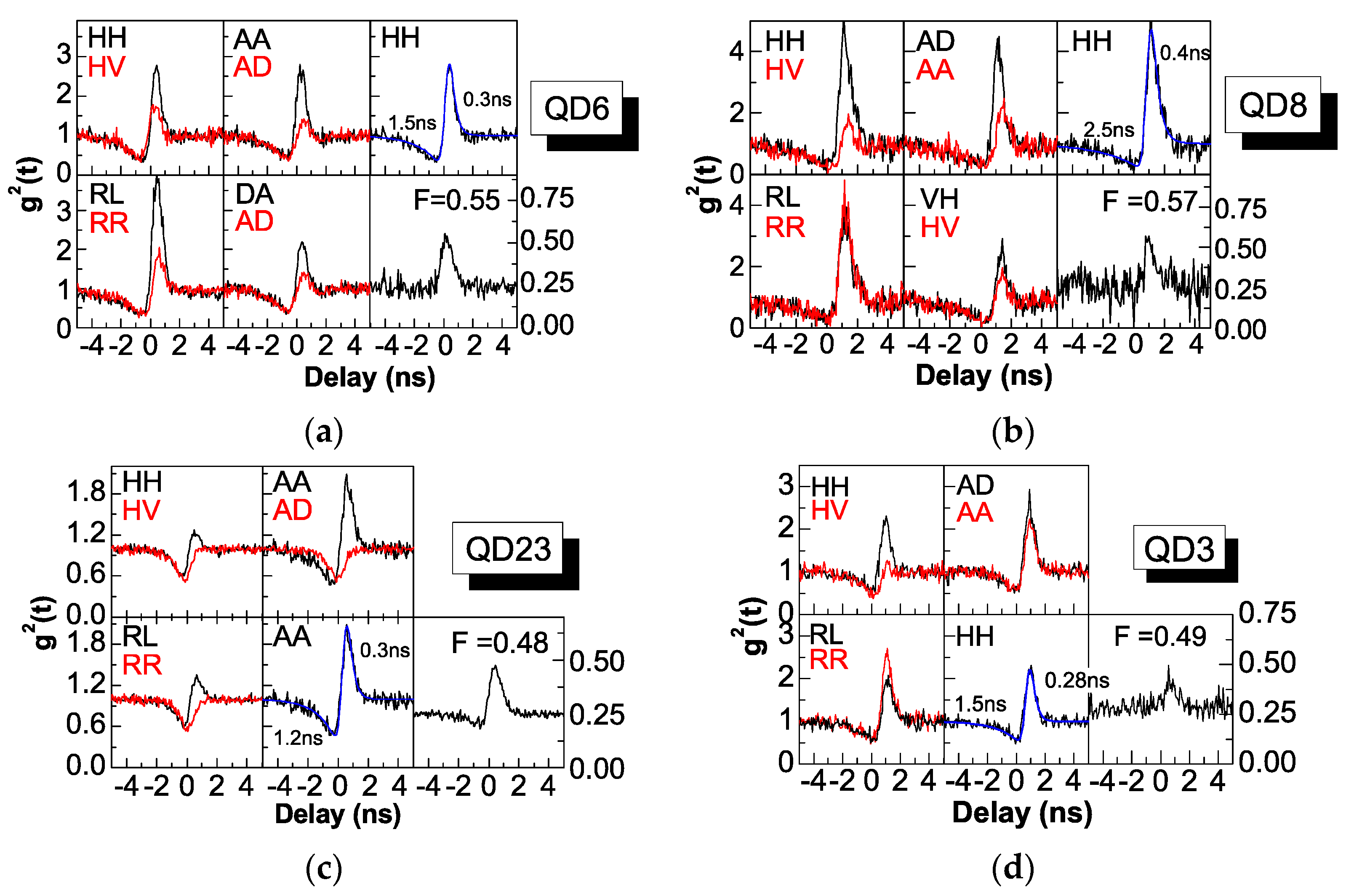
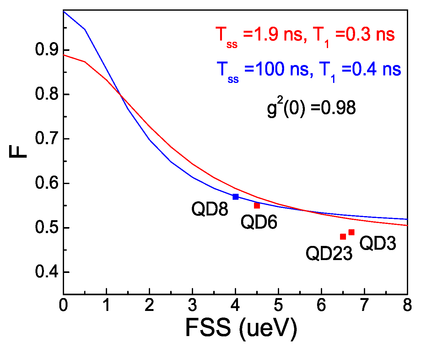
3.3. XX–X Photon-Pair Correlations

Figure 6 presents the measured polarization-resolved XX–X correlations in QDs with dominant X and XX emissions. A negative contrast in the RL/RR basis and a positive one in the HH/HV and AD/AA bases indicate the maximal entangled state |HH>+|VV> and F = (1+CHV+CDA-CRL)/4 to it: F = 0.55 in QD6 (FSS = 4.5 μeV), F = 0.48 in QD23 (6.2 μeV); both HH and HV bases show bunching, a little from spin precession in time h/FSS [3] (0.6 ns for FSS = 6 μeV) and mainly from spin flip with electrons in the barrier; a large correlation contrast remains in the AA/AD basis; in QD6 with a smaller FSS, the correlation contrast in the RR/RL basis is large (0.49), reflecting a nice restoring of X1–X2 degeneracy. QD8 and QD3 show a negative contrast in the AA/AD basis and a positive one in the RL/RR basis, reflecting F = (1 + CHV − CDA + CRL)/4 to the maximal entangled state |HH>−|VV>: F = 0.57 in QD8 (FSS = 4.1 μeV) and F = 0.49 in QD3 (FSS = 6.8 μeV), with a large contrast in the HH/HV basis (0.73 in QD8, 0.44 in QD3, in contrast to 0.21 in QD23 with nearly the same FSS as QD3) and a nearly zero contrast in the RR/RL basis since the lateral field has a large component on [1–10] to break X1–X2 wavefunction degeneracy and block spin flip between them, i.e., HH and VV cascade emissions are independent. This phenomenon is also clearly shown in QD7 in Figure 5, where the EIP (i.e., lateral field) was completely along [1–10] and the LX was nearly parallel to it for a large Stark shift, a large FSS and a large eh separation to break X1–X2 wavefunction degeneracy; like QD8, the correlation contrast in the HH/HV basis was 0.46 even for FSS = 22 μeV; the correlation contrast in the RR/RL basis was zero, reflecting independent HH and VV cascade emissions. There was no entanglement, while the robust HH/VV polarization correlations in this kind of QDs, insensitive on the FSS, can be used as photon-pair sources for quantum detection. The weak XX in QD8 was equivalent to a pulsed excitation of XX–X cascade emission to avoid XX repopulation for the highest HH bunching peak; it also showed a larger T1 ~0.4 ns. For QD3, Figure S2 in SM provides 18 combination of polarization-resolved XX–X correlations; the AA/AD and RL/RR bases show nearly zero contrast due to independent HH and VV emissions. The lh-hh mixing and EIP lead to unbalanced bunching peaks in the DA/AD or HV/VH basis. The deduced F is an optimal one excluding the unbalanced bunching and without background subtraction. Due to a finite lh-hh mixing (β ≤ 0.2), the two split lines HX and LX are nearly orthogonal linearly polarized [22,23] and can be purely filtered. Figure 7 plots these F we measured and the theoretical (F, FSS) curves (i.e., Equation 1 presented below, where f is the fidelity, gHV the fraction of photons uninfluenced by spin scattering, x and k the proportion of light exclusively emitted by the QD defined by T1, Tss and g2(0) given in the inset) [2,3]. QD6, QD3 and QD23 with T1 ~0.3 ns showed a reduced F from spin flip compared to the fitting curve with Tss = 1.9 ns; QD8 with T1 ~0.4 ns and weak XX (i.e., few electrons in the barrier for spin flip) showed a higher F, 0.57, little varied from the fitting curve prediction with Tss = 100 ns, reflecting little spin flip or spin scattering. A higher electric field to deplete these electrons as QDs in Figure 3 with AlGaAs barrier as capping [18,25,26,27] to reduce tunneling and a sub-bandgap optical excitation is desirable.
f = ( 1 + g H V + 2 k g H V / ( 1 + x 2 ) ) / 4 ,   g H V = ( 1 + T 1 / T s s ) 1 ,   x = FSS × g H V T 1 / ,   k = 1 g 2 ( 0 )

4. Conclusions

In conclusion, with a Si dopant above an (001)-based InAs/GaAs QD to build a local electric field, D3h symmetric excitons and small FSS ~4 μeV (with a possible zero minimum) are obtained, which facilitates the FSS erasure with a little junction field tuning. The diverse field projection in the lateral plane shows various FSS, LX and EIP with a universal field dependence; a strong vertical field is desired to restore X1–X2 degeneracy with no EIP. With FSS ~4 μeV and T1 ~0.3 ns in a DBR cavity, polarization-resolved XX–X correlations reflect cascade emission with a fidelity ~0.55 to the maximal entangled state |HH> + |VV>; spin flip from electrons in the barrier can be reduced with a weak XX excitation or in a higher electric field with these electrons depleted, combined with a sub-bandgap excitation. The breaking of wavefunction degeneracy with a lateral field along [1–10] ensures independent HH and VV cascade emission with robust polarization correlation and no spin flip, promising for photon-pair correlation applications.

Supplementary Materials

The following are available online at https://www.mdpi.com/article/10.3390/cryst11101194/s1, Figure S1: Excitation power-dependent μPL spectra in QD5 with more D3h exciton emission features and QD4 with similar D3h exciton emission features as QD1 and FSS ~11 μeV, Figure S2: Eighteen combinations of polarization-related XX–X correlations in QD3 (FSS = 6.8 μeV, F = 0.49), Figure S3: μPL spectrum, FSS oscillation and EIP in a polar plot in QD19.

Author Contributions

Conceptualization of QD structure, Z.N., X.S. (Xingjun Shang) and B.M.; methodology for QD growth and optical measurements, X.S. (Xingjun Shang), S.L., H.L., B.M., X.S. (Xiangbin Su) and H.N.; formal analysis, X.S. (Xiangbin Su), Y.C., J.S., H.H., X.D., Y.J., B.S., B.L. and Z.N.; investigation, X.S. (Xingjun Shang), S.L., and H.L.; validation, X.S. (Xingjun Shang), S.L., X.D.; resources, X.S. (Xingjun Shang); data curation, S.L., H.L. and Z.N.; writing—original draft preparation, X.S. (Xingjun Shang); writing—review and editing, X.S. (Xingjun Shang), S.L. and Z.N.; visualization, X.S. (Xingjun Shang); supervision, Z.N.; project administration, Z.N.; funding acquisition, Z.N. All authors have read and agreed to the published version of the manuscript.

Funding

This research was funded by the National Key Technologies R&D Program of China, Grant No. 2018YFA0306100), the National Natural Science Foundation of China (Grant No. 61505196), the Program of Beijing Academy of Quantum Information Sciences (Grant No. Y18G01), and the Scientific Instrument Developing Project of Chinese Academy of Sciences (Grant No. YJKYYQ20170032).

Data Availability Statement

The data that support the findings of this study are available from the corresponding author upon reasonable request.

Conflicts of Interest

The authors declare no conflict of interest.

References

  1. Keil, R.; Zopf, M.; Chen, Y.; Höfer, B.; Zhang, J.; Ding, F.; Schmidt, O.G. Solid-state ensemble of highly entangled photon sources at rubidium atomic transitions. Nat. Commun. 2017, 8, 15501. [Google Scholar] [CrossRef] [Green Version]
  2. Liu, J.; Su, R.; Wei, Y.; Yao, B.; Da Silva, S.F.C.; Yu, Y.; Iles-Smith, J.; Srinivasan, K.; Rastelli, A.; Li, J.; et al. A solid-state source of strongly entangled photon pairs with high brightness and indistinguishability. Nat. Nanotechnol. 2019, 14, 586–593. [Google Scholar] [CrossRef] [PubMed]
  3. Hudson, A.J.; Stevenson, R.M.; Bennett, A.J.; Young, R.J.; Nicoll, C.A.; Atkinson, P.; Cooper, K.; Ritchie, D.A.; Shields, A.J. Coherence of an Entangled Exciton-Photon State. Phys. Rev. Lett. 2007, 99, 266802. [Google Scholar] [CrossRef] [PubMed] [Green Version]
  4. Zhang, J.; Wildmann, J.S.; Ding, F.; Trotta, R.; Huo, Y.; Zallo, E.; Huber, D.; Rastelli, A.; Schmidt, O.G. High yield and ultrafast sources of electrically triggered entangled-photon pairs based on strain-tunable quantum dots. Nat. Commun. 2015, 6, 10067. [Google Scholar] [CrossRef] [PubMed]
  5. Chen, Z.-S.; Ma, B.; Shang, X.-J.; He, Y.; Zhang, L.-C.; Ni, H.-Q.; Wang, J.-L.; Niu, Z.-C. Telecommunication Wavelength-Band Single-Photon Emission from Single Large InAs Quantum Dots Nucleated on Low-Density Seed Quantum Dots. Nanoscale Res. Lett. 2016, 11, 382. [Google Scholar] [CrossRef] [Green Version]
  6. Tang, J.-S.; Zhou, Z.-Q.; Wang, Y.-T.; Li, Y.-L.; Liu, X.; Hua, Y.-L.; Zou, Y.; Wang, S.; He, D.-Y.; Chen, G.; et al. Storage of multiple single-photon pulses emitted from a quantum dot in a solid-state quantum memory. Nat. Commun. 2015, 6, 8652. [Google Scholar] [CrossRef] [Green Version]
  7. Birowosuto, M.D.; Sumikura, H.; Matsuo, S.; Taniyama, H.; Van Veldhoven, P.J.; Nötzel, R.; Notomi, M. Fast Purcell-enhanced single photon source in 1,550-nm telecom band from a resonant quantum dot-cavity coupling. Sci. Rep. 2012, 2, 321. [Google Scholar] [CrossRef] [Green Version]
  8. Sapienza, L.; Malein, R.N.; Kuklewicz, C.E.; Kremer, P.E.; Srinivasan, K.; Griffiths, A.; Clarke, E.; Gong, M.; Warburton, R.J.; Gerardot, B.D. Exciton fine-structure splitting of telecom-wavelength single quantum dots: Statistics and external strain tuning. Phys. Rev. B 2013, 88, 155330. [Google Scholar] [CrossRef] [Green Version]
  9. Seidl, S.; Gerardot, B.; Dalgarno, P.; Kowalik, K.; Holleitner, A.W.; Petroff, P.M.; Karrai, K.; Warburton, R.J. Statistics of quantum dot exciton fine structure splittings and their polarization orientations. Phys. E Low-Dimens. Syst. Nanostruct. 2008, 40, 2153–2155. [Google Scholar] [CrossRef]
  10. Su, D.; Dou, X.; Wu, X.; Liao, Y.; Zhou, P.; Ding, K.; Ni, H.; Niu, Z.; Zhu, H.; Jiang, D.; et al. Tuning exciton energy and fine-structure splitting in single InAs quantum dots by applying uniaxial stress. AIP Adv. 2016, 6, 045204. [Google Scholar] [CrossRef] [Green Version]
  11. Chen, H.; Zhuo, Z.; Huang, J.; Dou, X.; He, X.; Ding, K.; Ni, H.; Niu, Z.; Jiang, D.; Sun, B. Correlation between exciton polarized lifetime and fine structure splitting in InAs/GaAs quantum dots. Appl. Phys. Lett. 2020, 116, 082101. [Google Scholar] [CrossRef]
  12. Seguin, R.; Schliwa, A.; Germann, T.D.; Rodt, S.; Potschke, K.; Pohl, U.W.; Bimberg, D.; Winkelnkemper, M.; Hammerschmidt, T.; Kratzer, P. Control of fine-structure splitting and excitonic binding energies in selected individual InAs/GaAs quantum dots. Appl. Phys. Lett. 2006, 89, 263109. [Google Scholar] [CrossRef] [Green Version]
  13. Treu, J.; Schneider, C.; Huggenberger, A.; Braun, T.; Reitzenstein, S.; Höfling, S.; Kamp, M. Substrate orientation dependent fine structure splitting of symmetric In(Ga)As/GaAs quantum dots. Appl. Phys. Lett. 2012, 101, 022102. [Google Scholar] [CrossRef]
  14. Juska, G.; Dimastrodonato, V.; Mereni, L.O.; Gocalinska, A.; Pelucchi, E. Towards quantum-dot arrays of entangled photon emitters. Nat. Photon. 2013, 7, 527–531. [Google Scholar] [CrossRef]
  15. Mereni, L.O.; Marquardt, O.; Juska, G.; Dimastrodonato, V.; O’Reilly, E.P.; Pelucchi, E. Fine-structure splitting in large-pitch pyramidal quantum dots. Phys. Rev. B 2012, 85, 155453. [Google Scholar] [CrossRef]
  16. Karlsson, K.F.; Oberli, D.A.; Dupertuis, M.; Troncale, V.; Byszewski, M.; Pelucchi, E.; Rudra, A.; Holtz, P.O.; Kapon, E. Spectral signatures of high-symmetry quantum dots and effects of symmetry breaking. New J. Phys. 2015, 17, 103017. [Google Scholar] [CrossRef] [Green Version]
  17. Dupertuis, M.A.; Karlsson, F.; Oberli, D.; Pelucchi, E.; Rudra, A.; Holtz, P.O.; Kapon, E. Symmetries and the Polarized Optical Spectra of Exciton Complexes in Quantum Dots. Phys. Rev. Lett. 2011, 107, 127403. [Google Scholar] [CrossRef] [PubMed] [Green Version]
  18. Bennett, A.J.; Pooley, M.A.; Stevenson, R.M.; Ward, M.B.; Patel, R.B.; De La Giroday, A.B.; Sköld, N.; Farrer, I.; Nicoll, C.A.; Ritchie, D.A.; et al. Electric-field-induced coherent coupling of the exciton states in a single quantum dot. Nat. Phys. 2010, 6, 947–950. [Google Scholar] [CrossRef]
  19. Trotta, R.; Zallo, E.; Ortix, C.; Atkinson, P.; Plumhof, J.D.; Brink, J.V.D.; Rastelli, A.; Schmidt, O.G. Universal Recovery of the Energy-Level Degeneracy of Bright Excitons in InGaAs Quantum Dots without a Structure Symmetry. Phys. Rev. Lett. 2012, 109, 147401. [Google Scholar] [CrossRef] [Green Version]
  20. Huber, D.; Reindl, M.; da Silva, S.F.C.; Schimpf, C.; Martín-Sánchez, J.; Huang, H.; Piredda, G.; Edlinger, J.; Rastelli, A.; Trotta, R. Strain-Tunable GaAs Quantum Dot: A Nearly Dephasing-Free Source of Entangled Photon Pairs on Demand. Phys. Rev. Lett. 2018, 121, 033902. [Google Scholar] [CrossRef] [Green Version]
  21. Chen, Y.; Zhang, J.; Zopf, M.; Jung, K.; Zhang, Y.; Keil, R.; Ding, F.; Schmidt, O.G. Wavelength-tunable entangled photons from silicon-integrated III–V. quantum dots. Nat. Commun. 2015, 7, 10387. [Google Scholar] [CrossRef] [Green Version]
  22. Belhadj, T.; Amand, T.; Kunold, A.; Simon, C.-M.; Kuroda, T.; Abbarchi, M.; Mano, T.; Sakoda, K.; Kunz, S.; Marie, X.; et al. Impact of heavy hole-light hole coupling on optical selection rules in GaAs quantum dots. Appl. Phys. Lett. 2010, 97, 051111. [Google Scholar] [CrossRef] [Green Version]
  23. Tonin, C.; Hostein, R.; Voliotis, V.; Grousson, R.; Lemaitre, A.; Martinez, A. Polarization properties of excitonic qubits in single self-assembled quantum dots. Phys. Rev. B 2012, 85, 155303. [Google Scholar] [CrossRef] [Green Version]
  24. Abbarchi, M.; Mano, T.; Kuroda, T.; Ohtake, A.; Sakoda, K. Polarization Anisotropies in Strain-Free, Asymmetric, and Symmetric Quantum Dots Grown by Droplet Epitaxy. Nanomaterials 2021, 11, 443. [Google Scholar] [CrossRef] [PubMed]
  25. Wei, G.; Forrest, S.R. Intermediate-Band Solar Cells Employing Quantum Dots Embedded in an Energy Fence Barrier. Nano Lett. 2007, 7, 218. [Google Scholar] [CrossRef] [PubMed]
  26. Varghese, A.; Yakimov, M.; Tokranov, V.; Mitin, V.; Sablon, K.; Sergeev, A.; Oktyabrsky, S. Complete voltage recovery in quantum dot solar cells due to suppression of electron capture. Nanoscale 2016, 8, 7248. [Google Scholar] [CrossRef]
  27. Sablon, K.A.; Little, J.W.; Olver, K.A.; Wang, Z.M.; Dorogan, V.G.; Mazur, Y.I.; Salamo, G.J.; Towner, F.J. Effects of AlGaAs energy barriers on InAs/GaAs quantum dot solar cell. J. Appl. Phys. 2010, 108, 074305. [Google Scholar] [CrossRef]
  28. Li, M.F.; Yu, Y.; He, J.F.; Wang, L.J.; Zhu, Y.; Shang, X.J.; Ni, H.Q.; Niu, Z.C. In situ accurate control of 2D-3D transition parameters for growth of low-density InAs/GaAs self-assembled quantum dots. Nanoscale Res. Lett. 2013, 8, 86. [Google Scholar] [CrossRef] [Green Version]
  29. Shang, X.-J.; Xu, J.-X.; Ma, B.; Chen, Z.-S.; Wei, S.-H.; Li, M.-F.; Zha, G.-W.; Zhang, L.-C.; Yu, Y.; Ni, H.-Q.; et al. Proper In deposition amount for on-demand epitaxy of InAs/GaAs single quantum dots. Chin. Phys. B 2016, 25, 107805. [Google Scholar] [CrossRef]
  30. Ma, B.; Chen, Z.S.; Wei, S.H.; Shang, X.J.; Ni, H.Q.; Niu, Z.C. Single photon extraction from self-assembled quantum dots via stable fiber array coupling. Appl. Phys. Lett. 2017, 110, 142104. [Google Scholar] [CrossRef]
  31. Yu, Y.; Shang, X.-J.; Li, M.-F.; Zha, G.-W.; Xu, J.-X.; Wang, L.-J.; Wang, G.-W.; Ni, H.-Q.; Dou, X.-M.; Sun, B.-Q.; et al. Single InAs quantum dot coupled to different “environments” in one wafer for quantum photonics. Appl. Phys. Lett. 2013, 102, 201103. [Google Scholar]
  32. Li, S.L.; Shang, X.J.; Chen, Y.; Su, X.; Hao, H.; Liu, H.; Zhang, Y.; Ni, H.Q.; Niu, Z.C. Wet-etched microlens array for 200 nm spatial isolation of epitaxial single QDs and 80 nm broadband enhancement of their quantum light extraction. Nanomaterials 2021, 11, 1136. [Google Scholar] [CrossRef]
  33. Shang, X.-J.; Ma, B.; Ni, H.Q.; Chen, Z.S.; Li, S.L.; Chen, Y.; He, X.; Su, X.; Shi, Y.; Niu, Z.-C. C2v and D3h symmetric InAs quantum dots on GaAs (001) substrate: Exciton emission and a defect field influence. AIP Adv. 2020, 10, 085126. [Google Scholar] [CrossRef]
  34. He, L.; Gong, M.; Li, C.F.; Guo, G.C.; Zunger, A. Highly Reduced Fine-Structure Splitting in InAs/InP Quantum Dots Offering an Efficient On-Demand Entangled 1.55-um Photon Emitter. Phys. Rev. Lett. 2008, 101, 157405. [Google Scholar] [CrossRef] [PubMed] [Green Version]
  35. Nguyen, H.S.; Sallen, G.; Abbarchi, M.; Ferreira, R.; Voisin, C.; Roussignol, P.; Cassabois, G.; Diederichs, C. Photoneutralization and slow capture of carriers in quantum dots probed by resonant excitation spectroscopy. Phys. Rev. B 2013, 87, 115305. [Google Scholar] [CrossRef] [Green Version]
  36. Ramírez, H.Y.; Chou, Y.-L.; Cheng, S.-J. Effects of electrostatic environment on the electrically triggered production of entangled photon pairs from droplet epitaxial quantum dots. Sci. Rep. 2019, 9. [Google Scholar] [CrossRef]
  37. Ghali, M.; Ohtani, K.; Ohno, Y.; Ohno, H. Generation and control of polarization-entangled photons from GaAs island quantum dots by an electric field. Nat. Commun. 2012, 3, 661. [Google Scholar] [CrossRef] [PubMed] [Green Version]
Figure 1. (a) XX–X cascade emission, green: H [110] and blue: V [1–10], Txx and Tx: intrinsic XX and X radiative lifetimes, red dashes: exciton population, Te: population time, (b) a QD near a Si dopant, schematic band and epitaxial structures (grey region: QD; circle with ‘+’: Si donor; red dot: a possible defect >50 nm away from QD) and electron (green) and hole (red) wavefunctions, (c) AFM image of a typical QD, with symmetric morphological profile (red and black curves) in two orthogonal directions (red and white). Scale bar: 20 nm, (d) element angles for polarization measurement, detailed in the main text.
Crystals 11 01194 g001
Figure 2. Excitation power (black: weak, pink: moderate, wine: high)-dependent μPL spectra of three QDs with D3h symmetric XX21+, XX11 and X11+ exciton emissions, (a) QD1; (b) QD2; (c) QD24, and (d) QD21 (in a high field like QD24 and with a dominant X+). The numbers near exciton labels represent spectral linewidths. Insets: intensity excitation power dependence (slope marked, P0 = 25 μW) in (a) QD1 and (b) QD2; photon cross-correlations of XX+–X+ cascade in (a) QD1, XX–X cascade in (b) QD2, and X–X+ in (d) QD21 (fitting times are given); polarization-resolved FSS oscillations in (a) QD1 (FSS = 3.7 μeV, measured by a rotate LP only (45° corresponds to [110]) and extracted from a sinusoid fitting of the polarization-related XX–X relative energy offset), (c) QD24 (FSS = 3.9 μeV in X, 0 in XX and 32 μeV in X) and (d) QD21 (FSS = 7.1 μeV in both X and XX); EIP in a polar plot (orange arrow indicates the LX orientation); green line: along [110] with α = 67.5° (135° in polar plot), blue line: along [1–10] with α = 22.5°.
Crystals 11 01194 g002
Figure 3. (a) μPL spectra, FSS oscillation with fitting and EIP in polar plot (orange arrow indicates LX) of QD22 and QD25~27 in a strong vertical field with a dominant X+; (b) XX–X correlations in QD26 and QD27 (fitting times are given).
Crystals 11 01194 g003
Figure 4. μPL spectra and EIP (arrow indicates LX) of (a) left: QD23, QD6, QD3 and QD8 with a 10-nm capping and Si dopant varied from the center for a larger lateral field and (c) right: QD30 and QD29 un-doped, QD20 and QD28 with a 12-nm capping before dense Si dopant; (b) middle: their FSS oscillations with sinusoid fitting, blue: [1–10], green: [110]. Each QD is in a different color for clarity.
Crystals 11 01194 g004
Figure 5. QD7 with EIP along [1–10]. (a) μPL spectrum, FSS oscillation and EIP in polar plot (orange arrow indicates LX); (b) polarization-resolved XX–X correlations.
Crystals 11 01194 g005
Figure 6. Polarization-resolved XX–X cross-correlations in (a) QD6, (b) QD8, (c) QD23, and (d) QD3. The estimated F, the convoluted fitting (blue) and the fitting times are given.
Crystals 11 01194 g006
Figure 7. Experimental F of QDs we measured (QD3, QD8, QD6 and QD23) and theoretical (F, FSS) curves with g2(0), Tss and T1 given.
Crystals 11 01194 g007
Table 1. PA φ, LX θ and FSS for QDs. Sample A: with 10 nm GaAs capping before Si doping in density of 1 × 108 cm−2; Sample B: with 12 nm capping before Si doping in density of 5 × 108 cm−2; Sample C: with no doping. QD21, 22, 24~27: in a high vertical field; QD3, 6, 7, 8, 23 and QD19, 20, 28: with a lateral field projection.
SampleQD No.PA φLX θFSSSampleQD No.PA φLX θFSS
AQD24no103°3.9 μeVAQD25no10 μeV
AQD21105o158°7.1 μeVAQD26no-0 μeV
AQD22135o60°19.8 μeVBQD27100°12°34 μeV
AQD8−60o50°4.1 μeVBQD20−25°65°24 μeV
AQD3−45o50°6.8 μeVBQD19−20°55°5.9 μeV
AQD6−20o60°4.5 μeVBQD2820o110°53 μeV
AQD230o90°6.2 μeVCQD30no65°8.8 μeV
AQD790o110°22 μeVCQD2995°110°25 μeV
Publisher’s Note: MDPI stays neutral with regard to jurisdictional claims in published maps and institutional affiliations.

