Article

Effect of KyAl4(Si8-y) O20(OH)4 Calcined Based-Clay on the Microstructure and Mechanical Performances of High-Performance Concrete

by
David O. Nduka
1,*,
Babatunde J. Olawuyi
2,
Olabosipo I. Fagbenle
1 and
Belén G. Fonteboa
3
1
Department of Building Technology, College of Science and Technology, Km 10 Idiroko Road, Covenant University, Ota 112233, Nigeria
2
Department of Building, School of Environmental Technology, Federal University of Technology, Minna 920211, Nigeria
3
Department of Civil Engineering, School of Civil Engineering, University of A Coruña, 15001 A Coruña, Spain
*
Author to whom correspondence should be addressed.
Crystals 2021, 11(10), 1152; https://doi.org/10.3390/cryst11101152
Submission received: 19 August 2021 / Revised: 26 August 2021 / Accepted: 28 August 2021 / Published: 22 September 2021
(This article belongs to the Special Issue Properties and Performance of Concrete Materials and Structures)

Abstract

:
The work described in this paper has been performed to determine the potential use of meta-illite (KyAl4(Si8-y) O20(OH)4) calcined clay (MCC) as a supplementary cementitious material (SCM) in a binary Portland cement (PC) for high-performance concrete (HPC) production. To obtain the properties of the cementitious materials, the chemical composition, mineral phases, morphology, calcination efficiency and physical properties were quantitatively analysed using the advanced techniques of X-ray fluorescence (XRF), scanning electron microscopy/energy dispersive X-ray (SEM/EDX), X-ray diffraction (XRD), Fourier transform infrared/attenuated total reflection (FTIR/ATR), thermogravimetric analysis (TGA), laser particle sizing and Brunauer–Emmett–Teller (BET) nitrogen absorption method. The MCC’s effect on the workability and mechanical properties (compressive, splitting tensile and flexural strengths) and microstructure (morphology and crystalline phases) of hardened MCC-based HPCs were determined. The XRF result shows that the oxide composition of MCC confirmed the pozzolanic material requirements with recorded high useful oxides content. At the same time, the SEM image presents particles of broad, solid masses with a wider surface area of irregular shape. The XRD results show that the MCC was majorly an illite-based clay mineral calcined at a maximum temperature of 650 °C, as revealed by the TGA. The MCC addition increases the slump flow of HPCs at 5–15% cement replacement. The MCC incorporation at 10% cement replacement best improved the porosity of HPCs at a later age resulting in increased mechanical and microstructural properties of tested samples. Therefore, it is recommended that MCC addition within 10% cement replacement be adopted for low W/B Class I HPC at no deleterious results on mechanical and microstructural properties of the concrete.

1. Introduction

The past two decades have seen the rapid use of high-performance concrete (HPC) in constructing critical structural elements of super-tall buildings and other complex architecture, engineering, and construction (AEC) structures worldwide. HPC is an innovative high quality, and cost-efficient concrete compared to normal-strength concrete that meets the new generation’s desire for complex engineering structures [1,2]. Such a fact is not surprising because HPC had provided a pleasant living environment and safety in high-rise buildings and other AEC facilities. Specifically, HPC is essentially a concrete with a low-water-to-binder (W/B) ranging from 0.2–0.38 [3] that meets the performance challenges of structural elements regarding increasing heights, span length, and load. Moreover, many demonstrated AEC projects had been accomplished using HPC in many countries [4,5]. Therefore, the use of HPC in a developing country such as Nigeria would improve infrastructure projects’ future performances.
Among the various constituents of HPC, supplementary cementitious materials (SCMs) of pozzolanic nature play significant roles in meeting HPC requirements. SCMs are mainly siliceous/aluminous finely divided solid minerals used as partial/whole substitutes for cement in concrete and mortar production. SCM in the cement matrix will react chemically to deplete calcium hydroxide to form a more cementitious product later [6]. Significance of SCMs includes the refinement and improvement of pore size distribution; capillary pores and interfacial transition zone of hardened concrete; reduced large pores; improved density of cementitious products; improved workability in the fresh state; and lowering of W/B in HPC mix [1,7]. In addition, SCMs have also been documented to have the potentials to reduce carbon emissions generated during cement production and promising resources in lowering clinker content [8].
In this respect, thermally transformed illite-based clay presents a viable option as SCM in HPC due to the global availability, economic and circular economy attributes [9] and little effects on water demand and 28-day compressive strength [10], among others. Illite is a 2:1 structured aluminosilicate clay mineral sandwich of silica tetrahedron (T)—alumina octahedral (O)—silica tetrahedron (T) layers in the mica family [11]. Song et al. [11] gave the chemical formula as KyAl4(Si8-y) O20(OH)4, here y is estimated to be 1.5. The dehydroxylation of illite commences at about 350 ℃ and terminates at 800 ℃ with loss in crystallinity [12]. In a pozzolanic reactivity test, Avet et al. [12] showed that low-grade kaolinitic calcined clays’ compressive strength compared favourably with plain Portland cement. Zhuo et al. [6] demonstrated that abandoned London clay calcined up to 900 °C exhibited similar compressive strength properties with slag and pulverised fuel ash in concrete application. Trümer et al. [13] developed a binary cementitious material that consists of 30 wt.% of calcined bentonite clay and 70 wt.% of PC in concrete. They suggested that their calcined clay could apply to the majority of concrete works. Ferreiro et al. [14] indicated that 2:1 structured illite clay thermally activated at a temperature of 930 ℃ is appropriate for developing ternary calcined clay-limestone blended cement, which corresponds to improved workability and strength performance in concrete.
Also, Irassar et al. [15] experimentally studied the thermal transformation of raw illite-chlorite-based clay to understand the material production’s best calcination conditions for concrete use. Similarly, Laidani et al. [16] used bentonite-rich calcined clay as an SCM to improve self-compacting concrete’s fresh and hardened (i.e., mechanical and durability) properties. The authors reported improved compressive strength at 15–20% content of the calcined bentonite clay. Finally, Marchetti et al. [10] demonstrated the applicability and performance of illite calcined clay thermally activated at a temperature of 950 °C on a low-energy mortar. The authors’ findings revealed an enhanced packing density and compressive strength of mortar at a later age. Therefore, using illite calcined clay as a cement replacement could be regarded as a sustainable approach in HPC production due to the improved mechanical, durability and microstructural properties and minimisation of PC consumption.
With many studies conducted on HPC in many regions, information on HPC materials and structural properties produced with calcined clay is still scarce in Nigeria. The present study attempts to fill the gap in the literature by investigating the influence of meta-illite calcined clay (MCC) on Class 1 (50–75 MPa) HPC internally cured with superabsorbent polymers (SAP). The justification of this research is that for the first time, a Nigeria manufactured Pozzolan (NBRRI cement) named MCC in this study, which is readily available, is to be investigated as a binder component for use in HPC. This study will further provide direction to construction industry stakeholders on new materials that can revolutionise high-rise buildings and other heavy civil engineering infrastructural projects in developing countries such as Nigeria.

2. Materials and Methods

2.1. Materials

Portland-limestone cement (CEM II B-L, 42.5 N)—“3X” produced by Dangote cement PLC., Ibese Plant Ogun, State, Nigeria conforming to BS EN 197-1 [17], and NIS 444-1 [18] was used as the main binder. A commercially available Pozzolan (MCC) manufactured by the Pozzolan Cement Plant of the Nigeria Building and Road Research Institute (NBRRI), Ota, Ogun State Nigeria, served as the SCM. The SCM was incorporated in powdered form for the various HPC mixtures required by the mix design. Masterglenium Sky 504—a polycarboxylic ether (PCE) polymer-based superplasticiser supplied by BASF Limited (West Africa) was used to improve the workability of the HPC mixtures and administered within the manufacturer’s optimum specification of ≤2% by weight of binder (bwob). The specific gravity of the superplaticiser was 1.115, and it is chlorine-free. Superabsorbent polymers (SAP) tagged “FLOSET 27CC” ≥ 300 µm as described in an earlier publication of Olawuyi and Boshoff [19] at a constant content of 0.3% by weight of binder (bwob) was used as an internal curing agent. As specified by BS EN 1008 [20], potable water available within the concrete laboratory of the Department of Building Technology, Covenant University, Ota, was used for mixing.
The river sand used as fine aggregate was at the air-dry condition with a minimum particle size of 300 µm (i.e., all the particles smaller than 300 µm were removed using the sieving method) in compliance with the requirement of fine aggregate specification for HPC production [21,22,23]. Crushed granite stone passing through 13.50 mm sieve size and retained on 9.50 mm sieve size was used as coarse aggregate in compliance with typical HPC mixes found in the literature [4,22,23,24]. The crushed granite was used in saturated surface dry conditions after it has been washed to eliminate fine content that will likely increase water demand. Results of the physical characteristics of the materials are presented in Section 3.1. For a more scientific explanation of the binders, laser diffraction PSD, Brunauer–Emmett–Teller (BET) specific surface area (SSA), specific gravity, initial and final setting times, and soundness CEM II and MCC were determined. The binders’ PSD was performed using a Malvern Mastersizer 3000. The specific surface area of each binder was measured by nitrogen adsorption for the BET model using Nova Station B Quantachrome Instrument.
The powdery binder samples’ chemical compositions were investigated using a wavelength dispersive X-ray fluorescence (XRF) [Bruker AXS. S4, explorer]. The scanning electron microscopy/energy-dispersive X-ray(SEM/EDX) was performed to examine the binder’s samples’ morphology and microstructure using SEM (Model: Phenom ProX, PhenomWorld Eindhoven, Netherlands). The mineralogical phases of the binders were measured using a Rigaku Miniflex 600, Japan X-ray diffraction (XRD) technique adopting the reflection-transmission spinner stage of Theta-Theta settings. The two-Theta starting position was 2° and ended at 75° with a two-theta step of 0.026 at 8.67 s per step.
The MCC in powdery forms was analysed for functional groups using Cary 630 Fourier-transform infrared spectroscopy/Attenuated total reflectance (FTIR/ATR) spectrometer made by Agilent Technologies, Malaysia. The powdery sample was placed on the sample stage while the optimal spectra in the range of 500–4000 cm−1 were obtained at a high speed greater than 110 spectra/s. The calcination efficiency of MCC was analysed using the PerkinElmer thermogravimetry (TGA), the Netherlands, operating at a maximum temperature of 1200 °C and a maximum heat rate of 20 °C.

2.2. HPC Production

2.2.1. Mix Proportions

Table 1 shows the mix compositions of the seven HPC mixtures designed for 28-day Class 1, HPC having characteristic cube strength of 67 MPa (i.e., C55/67) following the margin for mix design. The equation can be written as: fm = fc + ks; where fm = target mean strength; fc = the specified characteristic strength; ks = the margin, which is a product of s = the standard deviation and k = a constant. The binder Type 1 (i.e., CEM II only) was adopted as an HPC control mixture and denoted as control. Binder Type 2 (i.e., CEM II + MCC) was adopted for MCCC-5 to MCCC-30 HPC mixtures. The MCCC-5 to MCCC-30 refers to the blend of CEM II with MCC from 5% to 30% at 5% intervals of SCM content adopted for the HPC mixtures. All the mixtures were prepared at a fixed W/B of 0.3%, fixed SAP content of 0.3% (bwob), and superplasticiser content (1.5% bwob). Additional water of 12.5 g/g of SAP was provided on the ground of the SAP absorbency determined by the work of Olawuyi [25]. Every constituent of HPC was measured by weight (kg/m3), and hence, the MCC addition was taken to be by weight of the binder. This same measurement was also adopted for SAP contents, as reflected in Table 1 following the British method of HPC design. Several studies have adopted the weight (%) method of cement replacement to arrive at their desired mix [6,26,27,28,29,30]. The HPC groups were designated with the name MCCC with MCC content reflected. For instance, the HPC containing MCC with 5% MCC content was coded as MCCC-5.

2.2.2. Batching Procedure and Curing Conditions

The fine aggregate was first poured into the 50-litre capacity pan-mixer, followed by the binders, which had first been thoroughly hand-mixed to enhance the MCC’s dispersion until a uniform colour was observed. After mixing for about 30 s, the dry SAP particles were then poured in, and all the fine contents were mixed for another 30 s. The coarse aggregate was then added, and mixing continued for another 1 min before water already mixed with superplasticiser (Masterglenium Sky 504—a PCE) was added. The mixing continued for another 3 min, as recommended in the literature [21,22,23,25]. Only about half of the mixer volume was maintained as the maximum volume of concrete produced per batch, noting that the mix is very stiff for these low W/B concrete and becomes difficult if 50% volume of the mixer is exceeded. Once the mixture met the required workability and consistency for the specified design mix, a specimen for the various tests was cast in two layers on a vibrating table into the previously oiled moulds. The cast specimen was then covered in the laboratory with thick vapour barriers (jute bags) and allowed to harden for 24 h, before demoulding and placed to cure immersed in water in a curing tank at 20 ± 3 °C till the requisite curing ages (7, 28, 56 and 90 days respectively) before testing in accordance to standards [31].

2.3. Test Methods

2.3.1. Workability

Slump flow measurement was conducted using the flow table test described in BS EN 12350-5 [32] to measure the workability of HPC mixtures.

2.3.2. Setting Times Test

The setting times (initial and final) of the HPC mixtures were determined using a penetration resistance method under ASTM C403 [33]. A standard 4.75 mm sieve was used to obtain mortar samples from the fresh HPC mixtures which were cast in two layers into 150 mm cube moulds to about 10 mm below the height edge. The specimens were then kept in a climate control room set at 24 ± 2 °C temperature and 70 ± 5% humidity. The pocket type H-4134 concrete mortar penetrometer was then used to measure the concrete’s resistance by forcing the penetrometer’s shaft into the mortar to a depth of 25 mm at a constant rate and time intervals. The resistance in MPa is shown on the penetrometer’s direct-reading scale. The initial set of concrete is reached when the penetration resistance is 3.50 MPa. The initial set is the semi-hardened, partially hydrated condition of the concrete beyond which it can no longer be worked or consolidated by vibration. The plot of penetration resistance on (Y-axis) against time in minutes (X-axis) gives the initial (3.5 MPa resistance) and final setting (27.6 MPa resistance) times, respectively.

2.3.3. Mechanical Properties

Compressive and splitting tensile strengths were determined in line with BS EN 12390-3 and 6 [34] and RILEM Technical Recommendation TC14-CPC 4 [35], respectively. 210 triplicates of 100 mm cubes and 126 Ø100 × 200 mm cylinders were used to investigate the compressive and splitting tensile strengths using the digitised materials testing machine (Model YES-2000, Eccles Technical Engineering Ltd., Eccles, England) with 2000 kN maximum loading capacity. In addition, 126 prismatic beams of 100 × 100 × 500 mm were tested for flexural strength test using a manually operated three-points contact 50 kN Impact AO 320 flexural machine following BS EN 12390-5 [36].

2.3.4. Non-Destructive Tests on HPC Mixtures

Selected HPC cube specimens of the respective MCC contents (control, 10% and 20%), at constant SAP cured for 90 days, were subjected to SEM-EDX and XRD examinations. Thus, this procedure enables the understanding of the effect of MCC contents on the mechanical behaviours of the HPC. SEM data was collected on thin sections of about 3 mm thickness samples after hydration stoppage. The hydration of the specimen was truncated by soaking the crushed HPC samples in acetone. XRD analysis of HPCs samples was carried out on remains of crushed hardened specimen passing through 75 μm standard sieve.

3. Results and Discussions

3.1. Material Characterisation

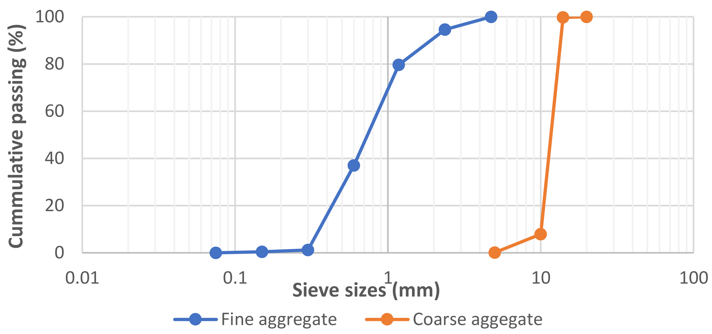
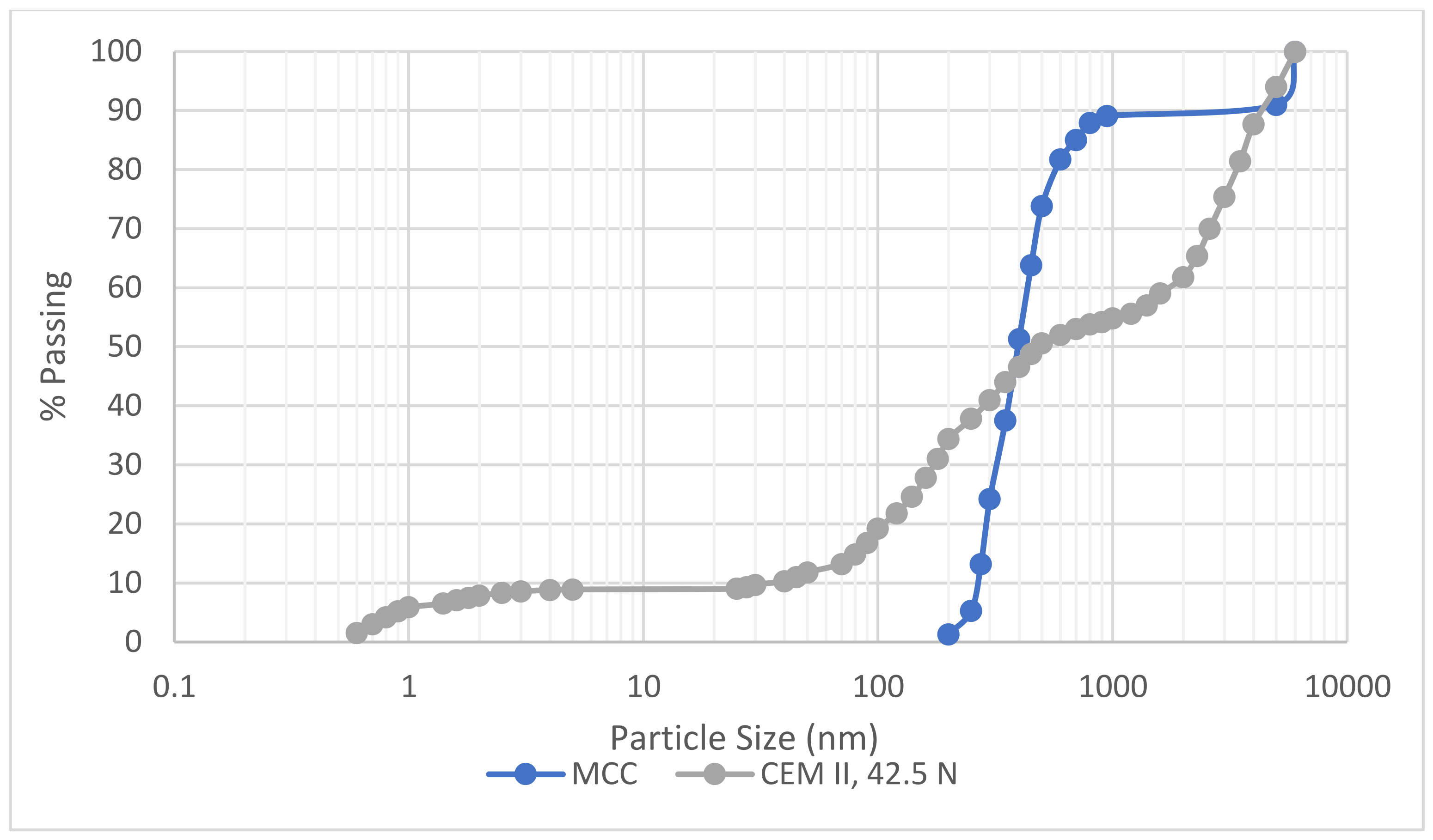
3.1.1. Physical Properties

The physical characteristics of the sand analysed through the sieve particle size distribution (PSD) were fineness modulus (FM) = 2.87; coefficient of uniformity (Cu) = 2.39; coefficient of curvature (Cc) = 0.94; dust content = 0.45%, specific gravity (SG) value of 2.65 and water absorption of 1.2% was recorded in the physical properties’ tests and presented in Figure 1 and Table 2, respectively. The granite analysed for the study had a specific gravity of 2.7, water absorption of 1.05%, aggregate crushing and impact values of 28% and 11%, respectively.
The PSD plot for the MCC and CEM II is presented in Figure 2, which shows that 90% (D90) of CEM II and MCC particles are smaller than 4000 and 950 nm, respectively. The median particle size, D50 of CEM II and MCC are 48.8 and 450 nm, respectively. Furthermore, the particle size below 10% (D10) falls within 4.88 and 275 nm, respectively, for the same samples. From Table 3, the SSA measured via the SinglePoint and MultiPoint BET model showed 5.590 × 10² and 3.026 × 10² m2/g and 8.182 × 10² and 4.649 × 10² m2/g for CEM II and MCC, respectively. The pore diameter of the binders analysed through the DA BET mode indicated corresponding values of 2.92 and 2.88 nm for CEM II and MCC samples. Based on these values, CEM II is finer than MCC. The differences in particle size seen in the binders may be attributed to the different production methods used. Comparing the two binders DA BET analysis, the MCC sample has a lower pore size diameter, conforming to macro-mesoporous material [37].

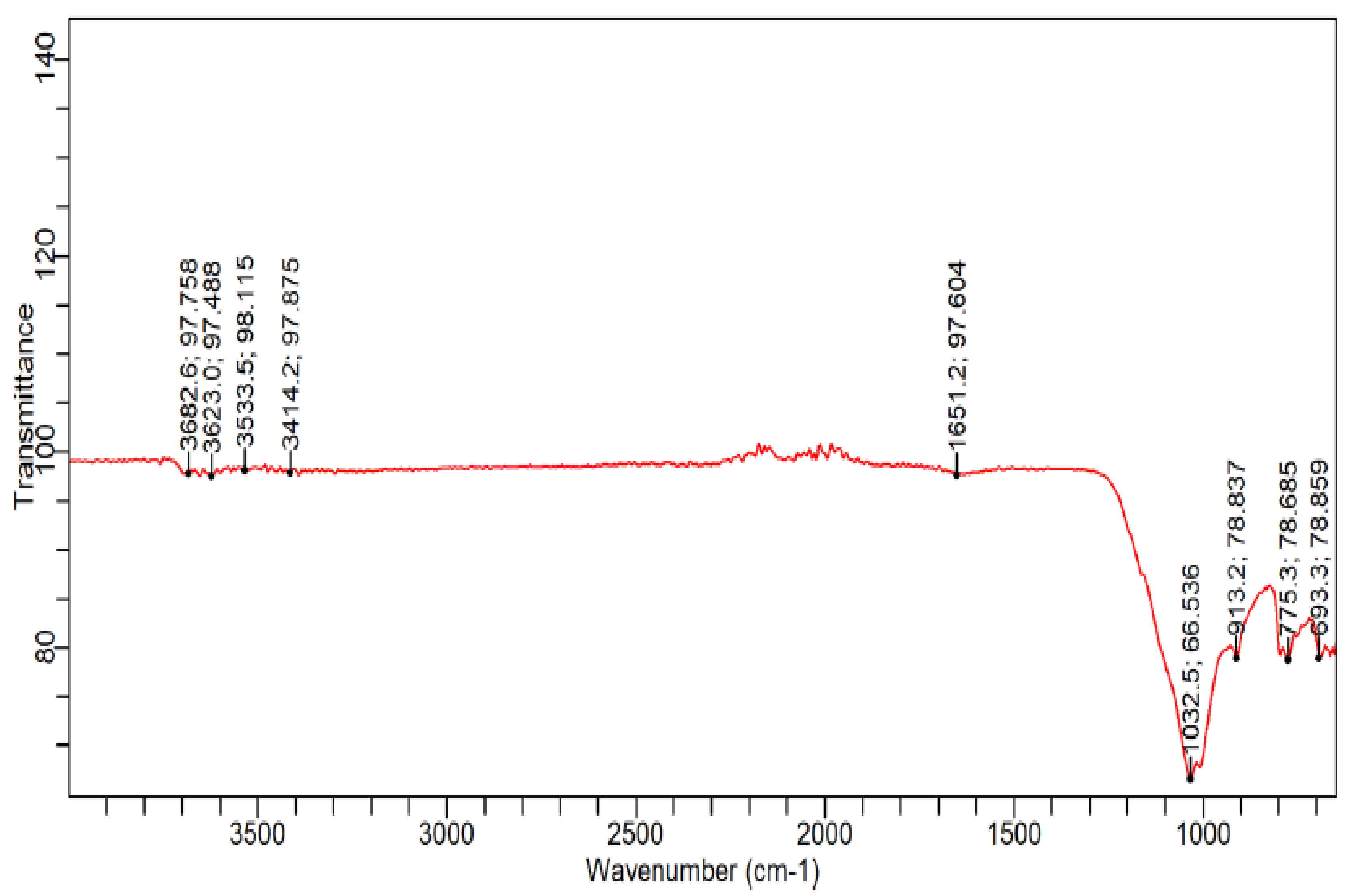
3.1.2. Chemical and Microstructure Analyses of Binders

Figure 3 depicts the morphology of the dark brown MCC powder at 200 µm XRF magnifications, revealing that MCC powder particles are broad, solid masses of the wider surface area and irregularly shaped. Table 4 further reveals that MCC mainly comprises SiO2, Al2O3 and Fe203 while CEM II oxide components are CaO, SiO2 and Al2O3.
The XRD phase spectra presented in Figure 4 shows that illite and kalicinite minerals dominate with 13% mineral contents of the MCC, followed by quartz with 8% mineral representation. Calcite and garnet recorded 6% mineral contents, respectively. Rutile recorded the least mineral content of 5% mineral.
The FTIR/ATR absorption spectra for MCC are shown in Figure 5. The spectra depict the intensities of the OH stretching, Si–O stretching and bending and Al–OH bending bands, indicating the development of kaolinite and illite minerals sensitive to cation exchange [38]. The OH stretching of the inner surface and the outer hydroxyl groups are observed at 3683, 3623 and 3534, 3414 cm−1 for sandwiched octahedral sheets between two layers for kaolinites tetrahedral-octahedral-tetrahedral structure of illite. The high region with a band at 3623 cm−1 resulted from the low frequency of kaolinites’ inner surface hydroxyls, indicating kaolinite and illite minerals sensitive to cation exchange [15]. The bands at 1651 cm−1 are due to the deformation of water molecules. Functional Al–OH bending bands at 1033–913 cm−1 typical for all smectite mineral clay groups are observed, thus validating the previous work on kaolin’s inner hydroxyls [39]. The vibrational modes of the octahedral aluminium ions of kaolinite and the Si–O stretching of quartz are recorded for the MCC sample at 693 cm−1 validating the XRD result.
Characterising the MCC for TGA (as shown in Figure 6) was borne out of knowing the dehydroxylation trend of the samples. The studied samples’ carbonation effects were controlled by maintaining the nitrogen environment with a 50 mL/min flow rate within the heating chamber. As shown in Figure 6, after subjecting the MCC sample to about 270 °C, the absorbed water located in the clay sample’s interlayer space got dehydrated. Further measurement to about 350 °C to 450 °C, brought about dehydroxylation of possible kaolinite. At 500 °C, it shows complete dehydroxylation of the remaining kaolinite. At about 650 °C to 888 °C, the TGA curve remains flattened, showing the maximum calcination temperature to which MCC manufacturers subjected the raw clay material. Zhou [39] averred that at 800 °C, a compete dehydroxylation of illite and montmorillonite clay minerals appears. Garg and Skibsted [40] pointed out that illite/smectite mineral-based clay attains dehydration, dehydroxylation, amorphisation and recrystallisation at the temperature ranges of 25 to 200 °C; 600 to 800 °C; 800 to 900 °C; 950 °C and above, respectively. Thus, the MCC showed an amorphous phase considering the flattering of the TGA curve from 650 °C to 888 °C and supports the postulations of Garg and Skibsted [40].

3.2. Fresh Properties

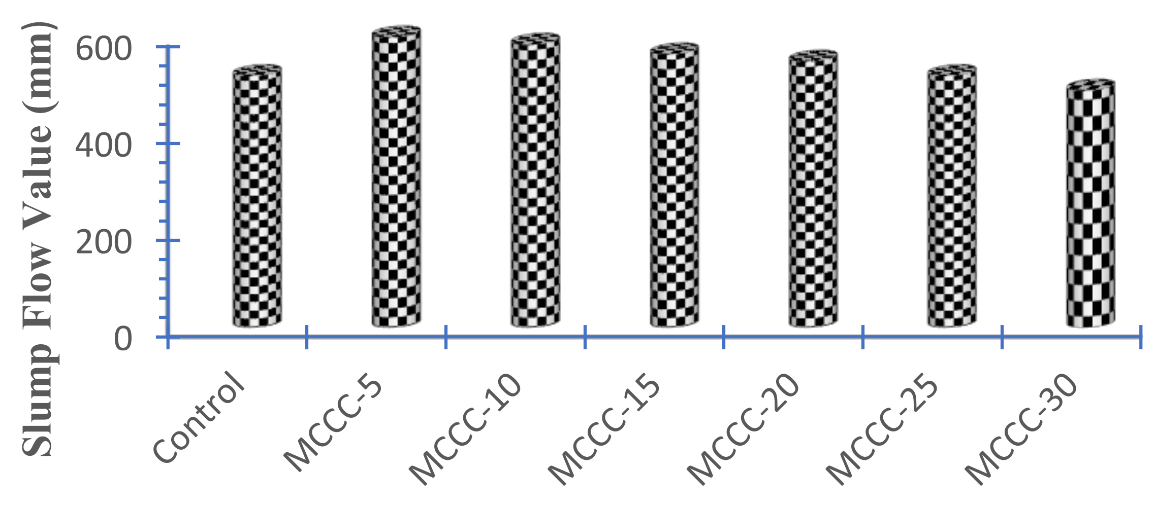
3.2.1. Slump Flow Test

Before casting into moulds, fresh HPC mixtures were examined for workability by slump flow test. The slump flow test results on the HPC mixtures containing MCC is presented in Figure 7.
The result demonstrates an average flow value of 520 mm for the control mixture. In contrast, the mixtures containing MCC show an improvement inflow up to 20% MCC content. Specifically, there is an improved flow of 15.39%, 12.50%, 8.65%, and 5.77% for MCCC-5 to MCCC-20 compared with the control. MCCC-25 recorded the same flow value as the control, while MCCC-30 had a 5.77% decrease in flow value. These findings suggest the MCC’s ability to absorb the Masterglenium Sky 504—a PCE superplasticiser used in the study, causing the dispersion and water reduction tendencies affecting MCC-based HPC [41,42,43]. The lowest flow value observed by the control mixture may be linked to the more angular shape of the CEM II particle size as compared with the broad irregular shape of clay particle size, as corroborated by SEM characterisation. However, the data obtained from slump flow tests is consistent with HPC mixtures in literature, with a slump flow range of 450–600 mm [23].

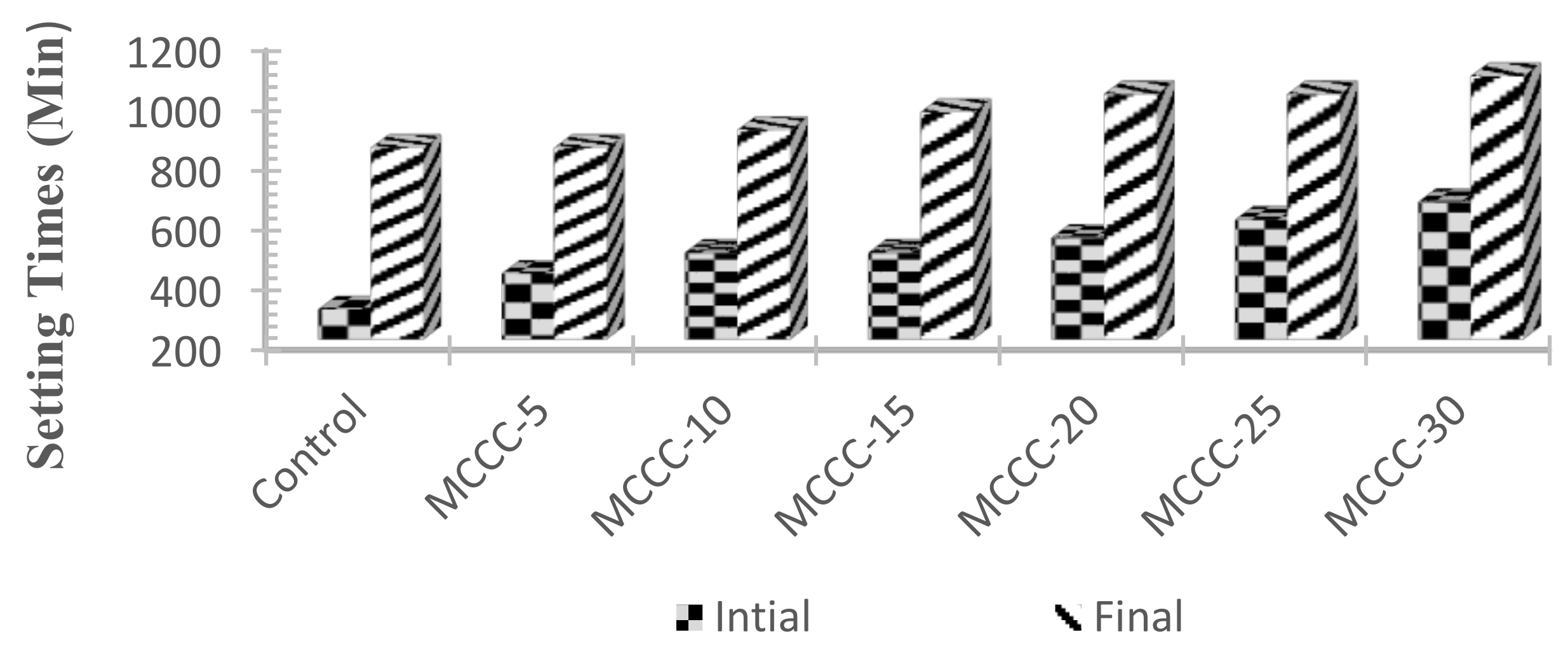
3.2.2. Initial and Final Setting Times

Figure 8 portrays the setting times test results for the various binary blend of HPC mortar mixtures using a concrete penetrometer under ASTM C403 [33]. From Figure 8, MCC-based HPC mixtures show that MCC’s addition resulted in a gradual increase in the HPC’s initial and final setting times. The initial setting time for control, MCCC-5, MCCC-10, MCCC-15, MCCC-20, MCCC-25 and MCCC-30, is 300, 420, 490, 540, 600, and 660 min, respectively and observed to be higher than the control. From the same Figure, the final setting times for control, MCCC-5, MCCC-10, MCCC-15, MCCC-20, MCCC-25 and MCCC-30 are 840, 840, 900, 960, 1020, and 1080 min, respectively. As observed from Figure 9, a relatively lower final setting time occurred in MCC modified HPCs than the initial setting time. The higher initial and final setting values seen for the HPC mixtures are linked to MCC’s gradual addition into the HPCs. Cia et al. [44] inferred that the retardation of setting conditions for Portland cement pastes containing mineral clay is connected with the concentration influence of mineral clay and the partial performance of clay mineral’s pozzolanic reactivity at an early age.

3.3. Mechanical Properties

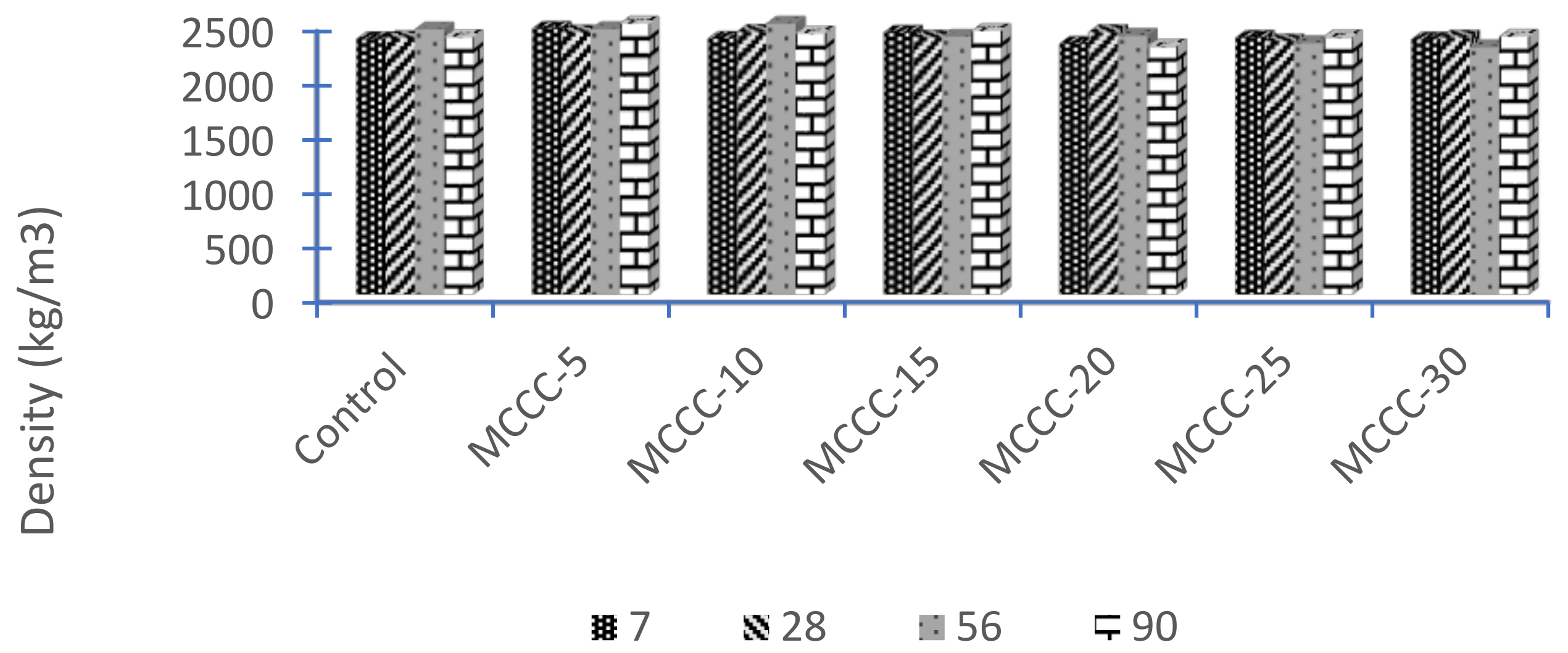
3.3.1. Density of HPC

The average dry densities of the control and various MCC-based HPCs at 7, 28, 56 and 90 hydration days are presented in Figure 9. The figure shows that the average density of the activated HPC samples containing MCC and the control varies from 2390 kg/m3 to 2387 kg/m3 for all ages. It also showed that the densities slightly increased by 0.04% as the curing age increases. Comparing the individual HPCs containing MCC and the CEM II, MCCC-5, MCCC-10, and MCCC-15 showed an average increase in dry densities of 2.92%, 1.80% and 0.46% over the control, respectively.
MCCC-20, MCCC-25, and MCCC-30 showed decreased dry densities corresponding to 1.35%, 1.51%, and 1.62% compared to the control over the ninety-day observation. The initial increases in density with lower MCC contents (MCCC-5 to MCCC-15) may be attributed to the binary combination of the cementitious materials filling the voids between the fine aggregates, thereby achieving a denser assembly. The fact that the dry densities of MCCC-5, MCCC-10 and MCCC-15 were improved, which was not the case for MCCC-20, MCCC-25 and MCCC-30, could be the reason that MCC was added as CEM II, replacement by weight. When incorporated to substitute cement to a higher mass, MCC has a lower density, the total volume of powder (CEM II+ MCC) was increased. The addition of MCC’s higher weight with PSD closer to CEM II may have reduced the HPC density. This result agrees well with Zhou’s [39] reported lower density with the higher replacement of London calcined clay in concrete.

3.3.2. Compressive Strength of HPC with MCC

HPC specimens’ compressive strength data having MCC tested at 7, 28, 56 and 90 days are presented in Figure 10. HPC specimen with 5% cement replacement (MCCC-5) had the highest compressive strength at 7 days curing age, followed by MCCC-15, control, MCCC-20 and MCCC-25. There are comparable strength values between the control and the MCC-based HPCs. The control specimen showed a superior strength value at 28 days among other HPCs of the same age. On the other hand, the MCCC-10 HPC specimen had the highest compressive strength at 56- and 90-days curing ages, followed by MCCC-5 and MCCC-15 mixture types. MCCC-25 and MCCC-30 had a reduced strength at 56 and 90 days compared to control. The control and specimen with a higher MCC content had lower strength at later age following dilution effects and high content of calcined clay with low pozzolanic reactivity [6].
The HPC samples with higher MCC contents produce lower C3S, b-C2S phases, and high-water demand for cement hydration, giving room for decreased compressive strength [16]. The 56 and 90 days MCC-based HPC specimens gained strength at a greater rate than the control. Strength development continues beyond 28 days, and this result demonstrated later age minor pozzolanic reactions, filler effect, MCC fineness and cement hydration accomplishment [45]. It can be inferred that the insignificant content of decomposed kaolinite found in the MCC also had a marginal compressive strength impact on the HPCs design mix.
As NBBRI Pozzolan (MCC) was never used for HPC development before, the comparison with other researchers’ results had to be done with similar compositions. Vejmelková et al. [46] prepared a ternary HPC mix containing 10–60% CEM I, 52.5 R cement class replaced with an industry prepared calcined Czech claystone calcined at a maximum temperature of 700 °C and silica fume with a target design strength of 120 MPa. The XRD analysis revealed that the mineralogical compositions of the clay were mostly kaolinite and illite. The authors achieved over 120 MPa compressive strength with 10, 20 and 30% replacements at 28, 90, 180- and 365-days age curing. The best result of Vejmelková et al. [46] was observed at 30% of the clay with compressive strength of ~20% higher than the control. Thus, the attainment of over 120 MPa may be linked to the introduction of silica fume and 1:1 clay structure in the HPC matrix, leading to their samples’ improved microstructure. Trümer et al. [13] obtained a C40/50 concrete class with a 30/70 ratio with a CEM I, 42.5 R and calcined montmorillonite-based clay. The raw bentonite’s calcination up to 900 °C brings about the total decomposition of montmorillonite mineral culminating in the clay’s amorphousness and attainment of the designed strength. Schulze and Rickert [45] reached a strength class of 42.5 N using calcined clay, irrespective of the clay minerals (kaolinite, montmorillonite and muscovite/illite) content investigated. Laidani et al. [16] reported compressive strength of 74 and 70 MPa as their most successful strength, with 5% to 30% of calcined illite and quartz mineral-based clay in the cement-based blend. They found that their best mix showed an improved compressive strength of 20% and 15% over the control.
Strong evidence emanating from the entire result showed that blended CEM II with MCC could not produce the target designed strength of Class 1 HPC (50–75 MPa) at 28 days, while later age curing showed a promising result. Garg and Skibsted [40] pointed out that when illite/smectite clays are blended with Portland cement in mortar and concrete; there appears to be a little form of clay reaction at an early age while there is usually a considerable amount of reaction in a clay-based mortar or concrete mixtures at a later age. A further shortfall in the rate of strength development at an early age may be linked to the MCC’s lower calcination temperature below 700 °C.

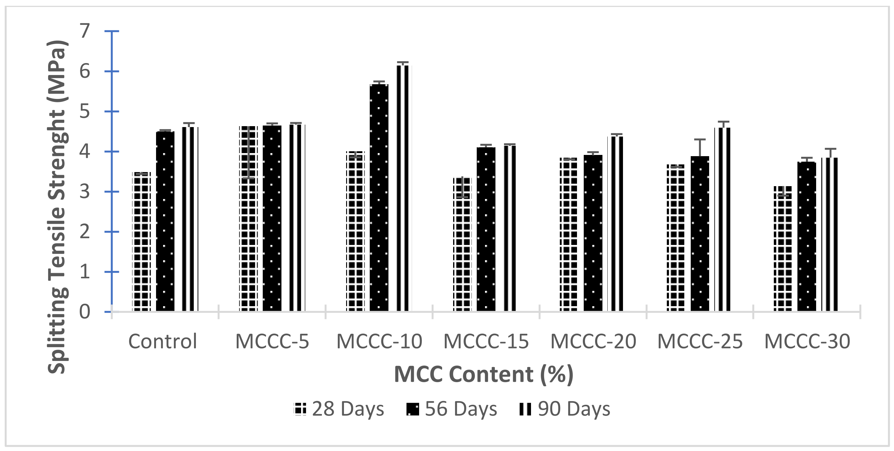
3.3.3. Splitting Tensile Strength of HPCs with MCC

Splitting tensile strength results of HPCs with varied MCC contents is presented in Figure 11.
From Figure 11, the 28 days of hydration period of MCCC-5, MCCC-10, MCCC-20 and MCCC-25 enhances good splitting tensile strength value of the HPCs than the control. Only the splitting strength value of MCCC-10 was higher by 20.64% than the control specimen at 56 days. At the same age, MCCC-5, MCCC-15, MCCC-20, MCCC-25 and MCCC-30 decreased in strength with ~7%, 9%, 13%, 14% and 17%, respectively compared with control mix. Comparing 90 days splitting tensile strength values of MCCCs with control (4.61 MPa), MCCC-10 performed best with 6.15 MPa, followed by MCCC-5 with a slight margin of 4.67 MPa. Other MCCCs (MCCC-15, MCCC-20 and MCCC-25) recorded close splitting strengths values of 4.14, 4.37 and 4.59 MPa with control. Only MCCC-30 had a decreased value of about 16% compared with the control. The addition of MCC has a moderately positive effect on the splitting tensile strength of the HPC, especially at later hydration ages. These results indicate that 10% cement replacement with MCC (MCCC-10) is sufficient to accelerate 28, 56 and 90 days splitting tensile strength of the HPCs. These results were consistent with the splitting tensile strength result found in the literature [40,46].

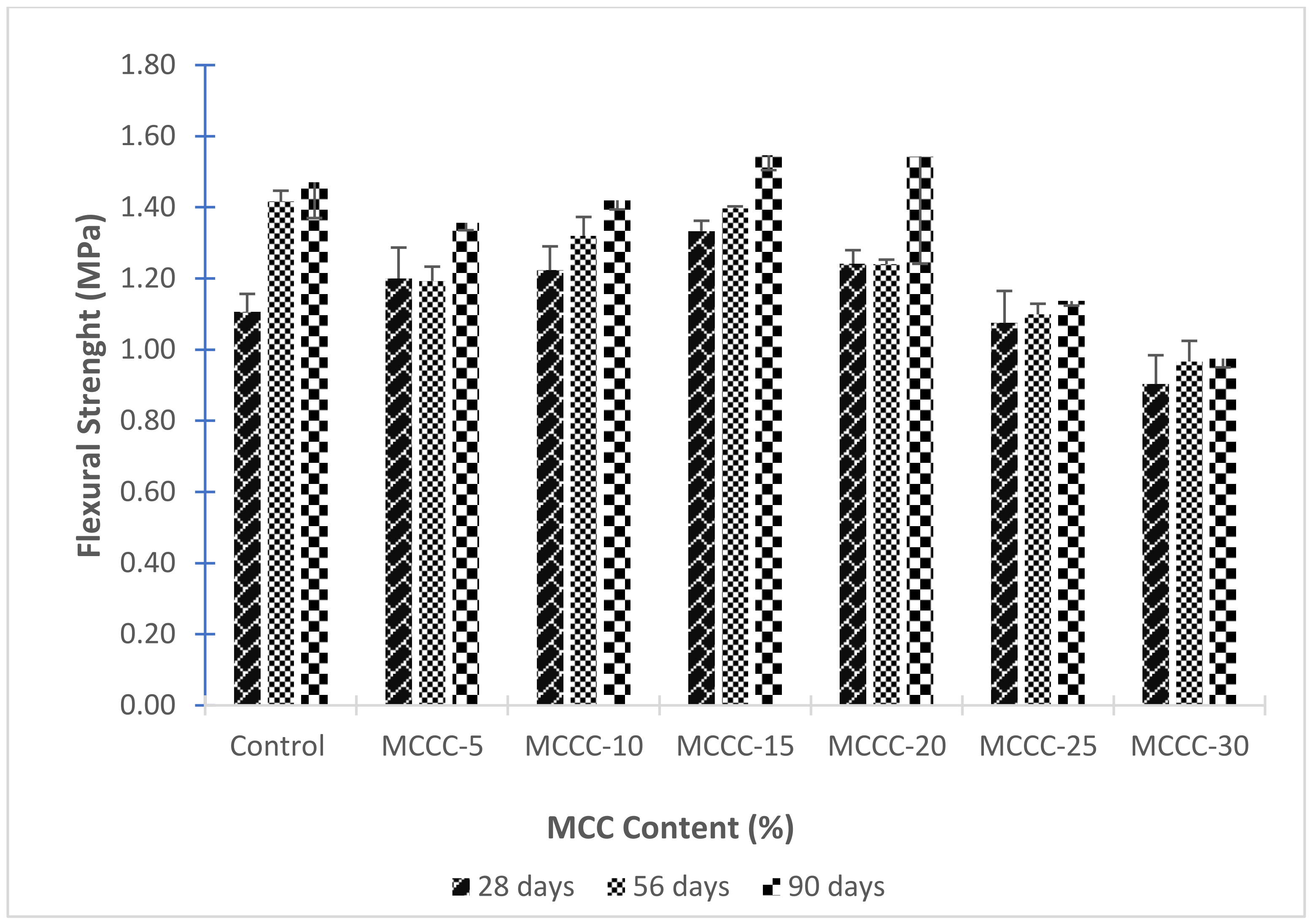
3.3.4. Flexural Strength of HPCs with MCC

Flexural strength (modulus of rupture) results of HPCs as influenced by the MCC content is presented in Figure 12.
At 28 days, for Figure 12, the HPC mixes with MCC had higher flexural strength than the reference mix, which can be attributed to the pozzolanic reactivity of MCC compared to the control mix at 28 days. The MCCC-15 with 15% cement replacement with MCC had the highest flexural strength (1.40 MPa). As the hydration progressed for 56 and 90 days, the strength increased faster with MCC mixes than the reference, especially for mix MCCC-15 and MCCC-10, indicating that MCC’s pore structure refinement was more efficient in these mixes than others. Possible explanations for the strength improvement are contained in the studies of Garg and Skibsted [40], Zhou et al. [6], Vejmelková et al. [46] and Trümer et al. [13].

3.4. Non-destructive Tests on Hardened HPC Mixtures

SEM/EDX was conducted on selected HPC samples (Control, 10% and 20%) in furtherance to quantitatively assess the hydration products, molecular structure and the bond between the cement paste and aggregate at the interfacial transition zone (ITZ). The SEM images taken at 100 and 200 µm and oxides atomic concentrations for the control, MCCC-10 and MCCC-20 specimen at 90 days, are shown in Figure 13, Figure 14, Figure 15 and Table 5, respectively.

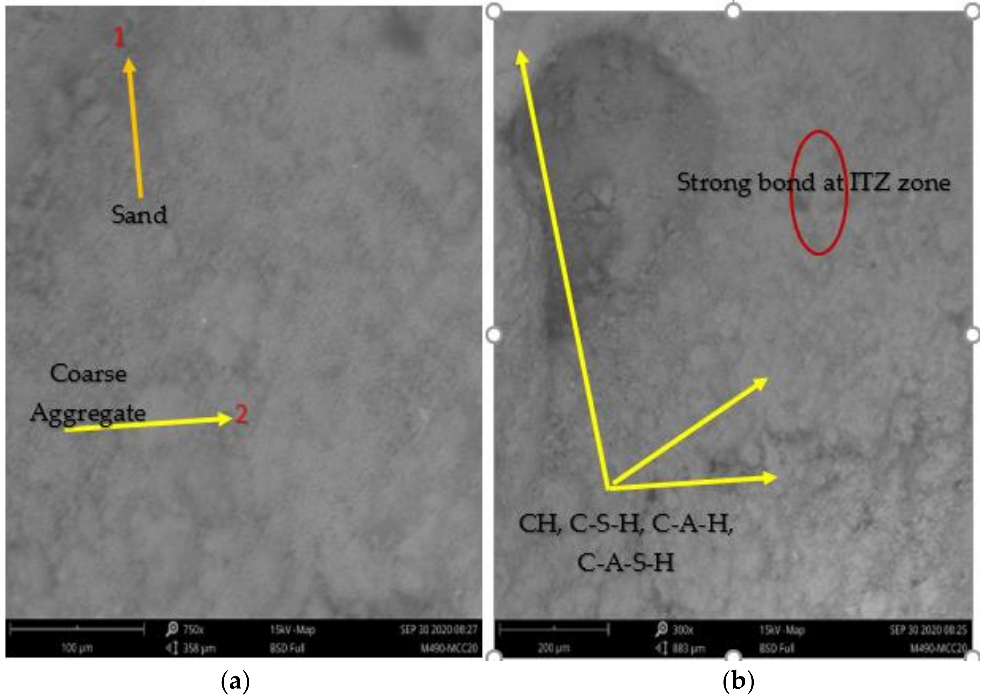
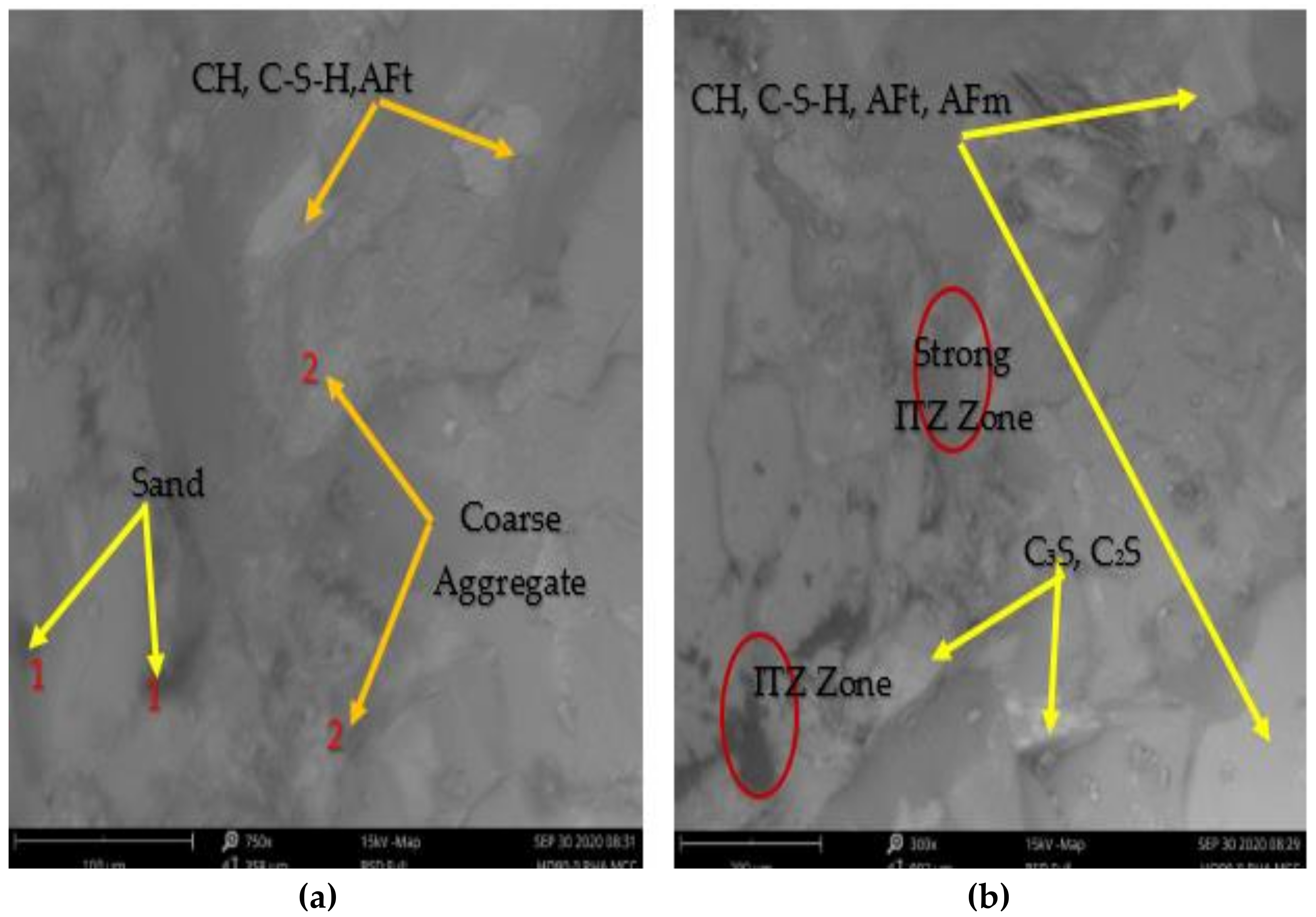
3.4.1. SEM/EDX Analysis
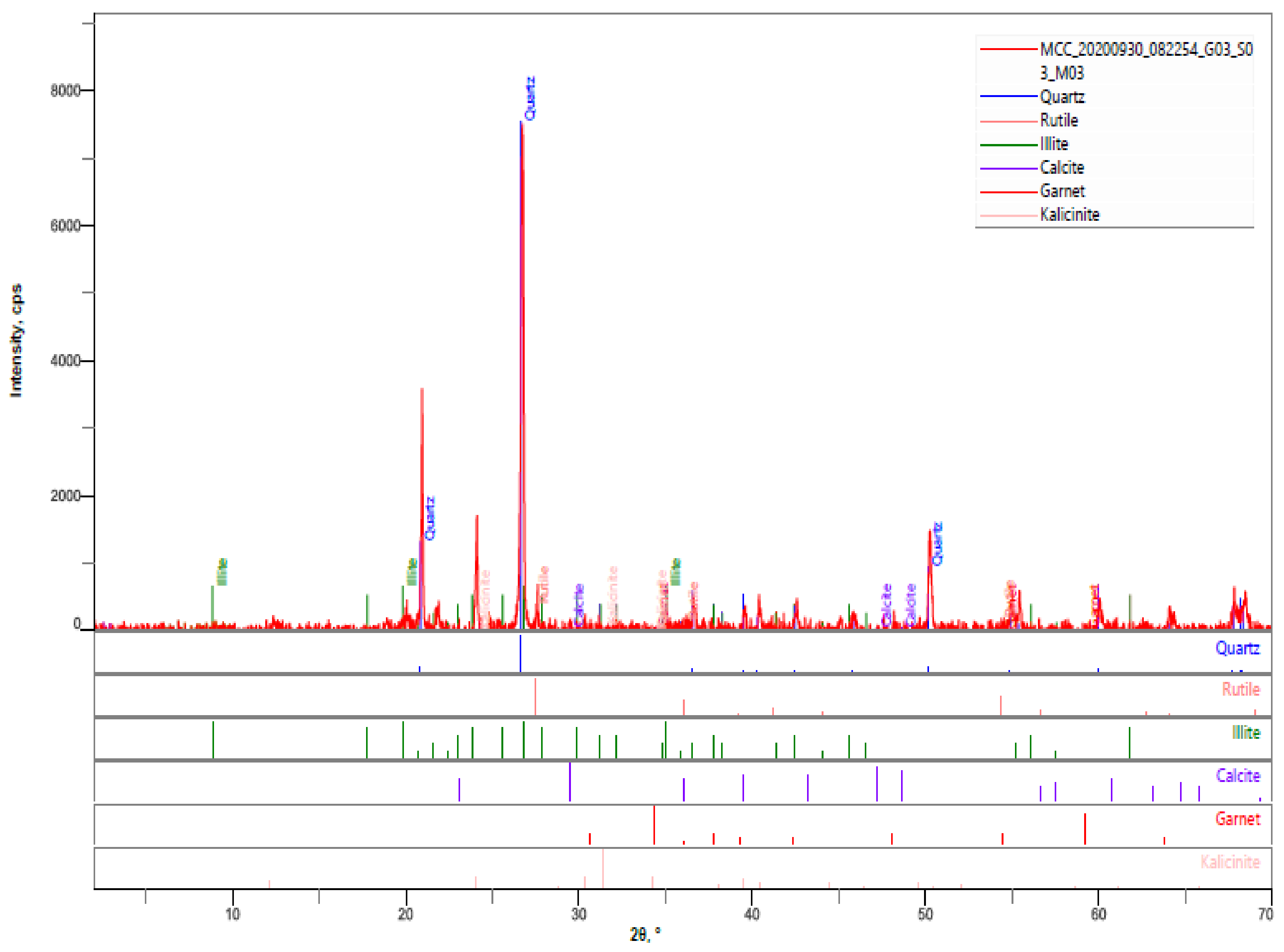
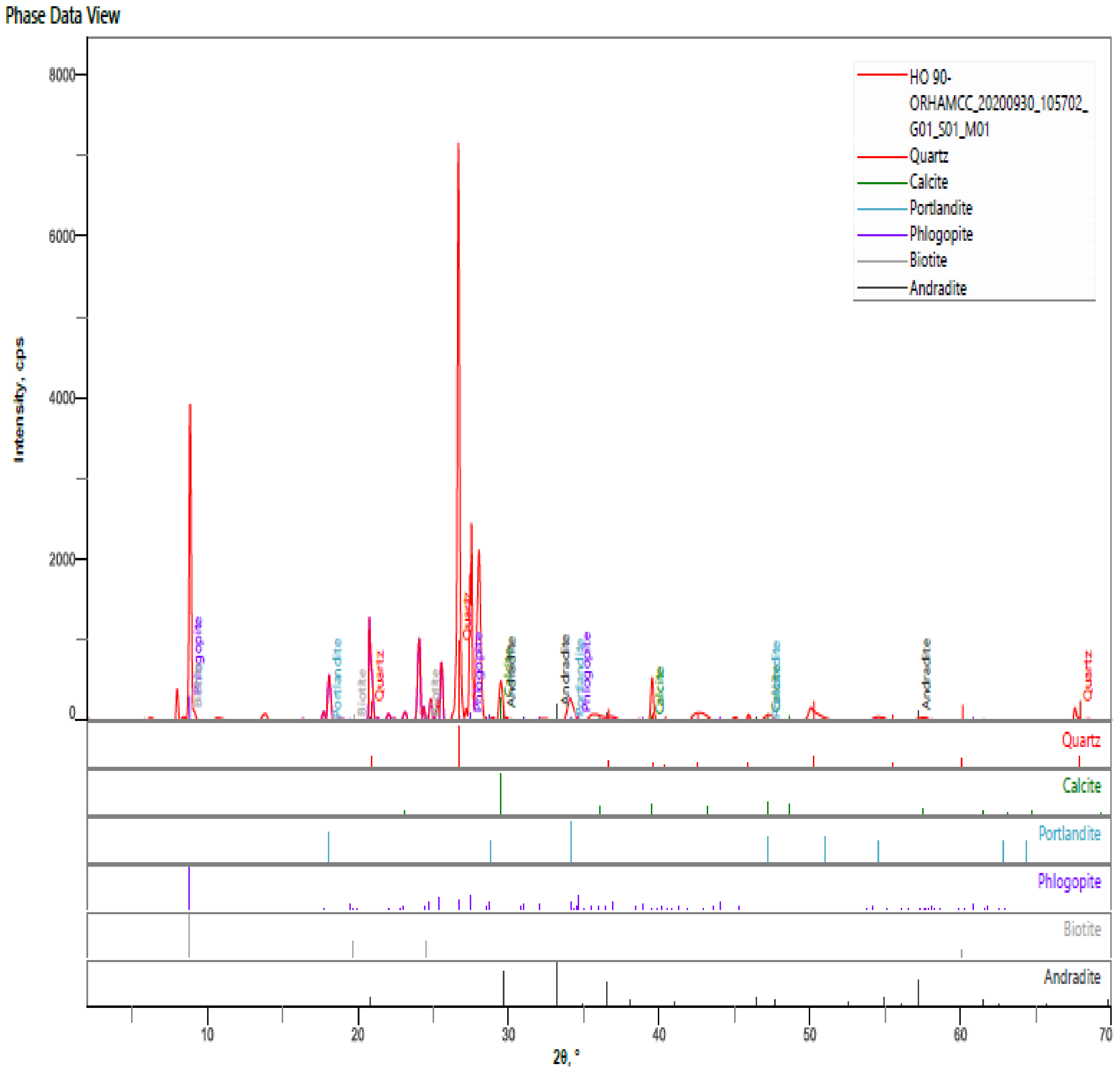
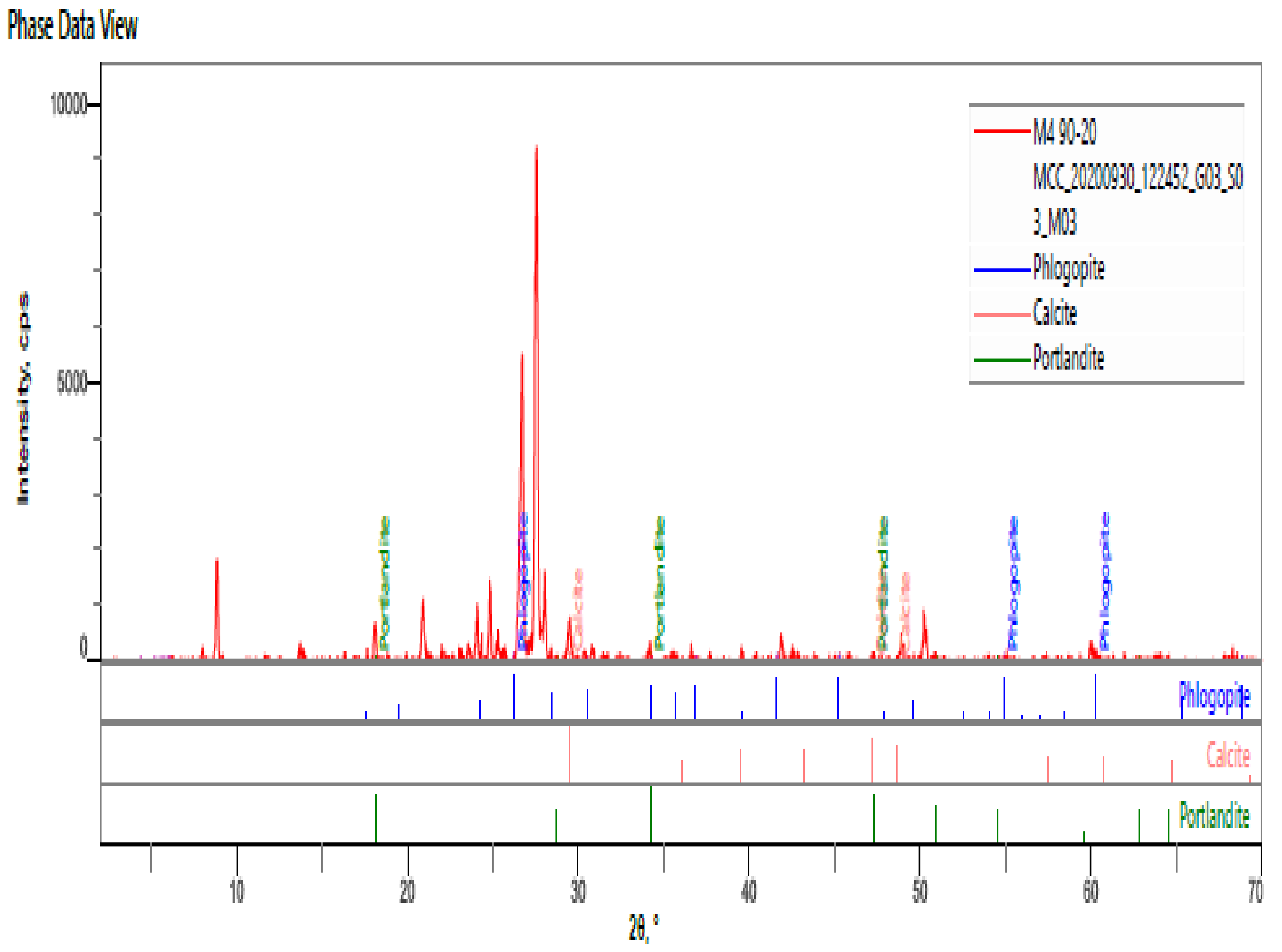
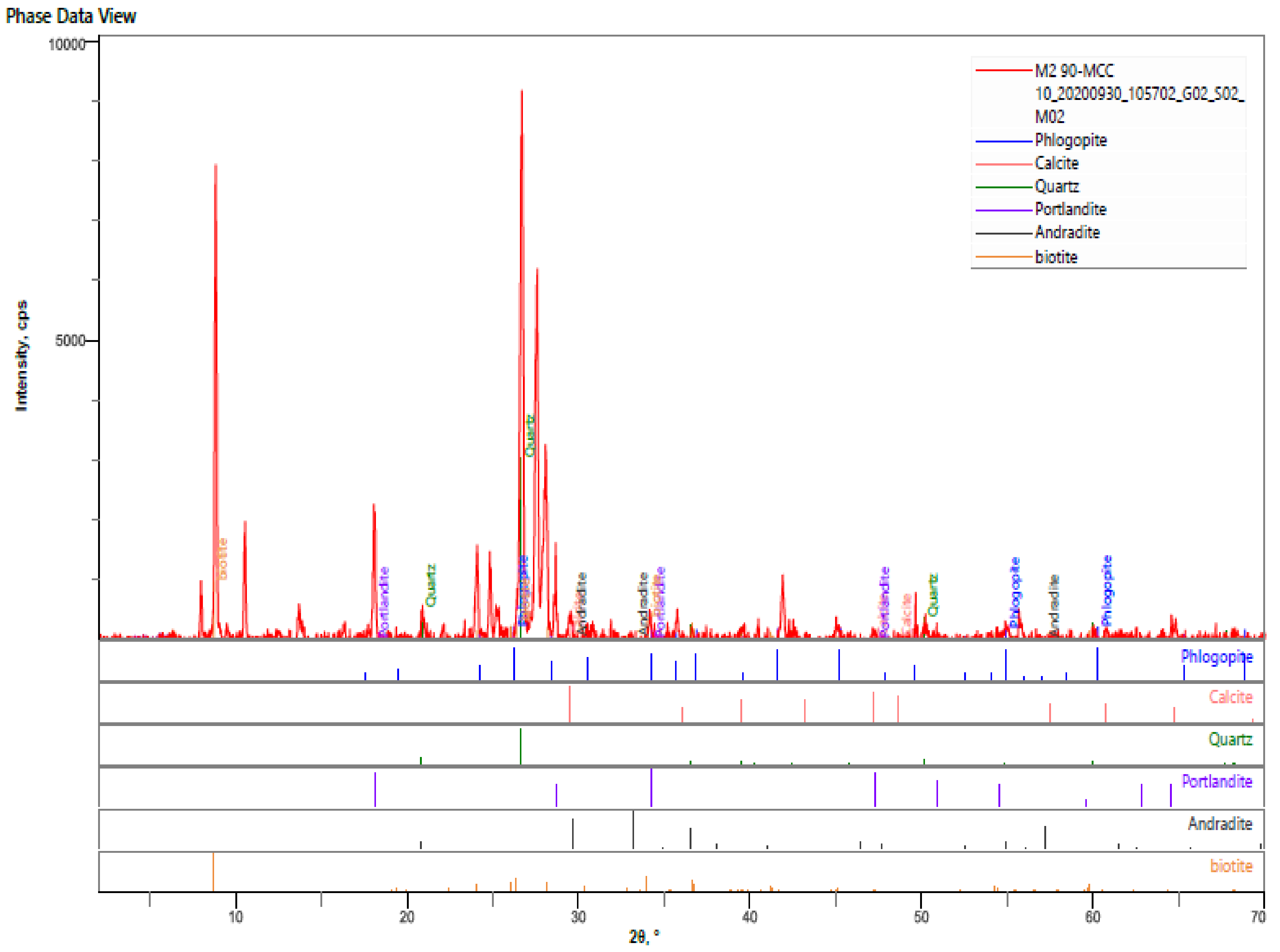
Figure 13a,b depicts the SEM images of the reference HPC. The images revealed the general morphology and crystalline structure of the internal surface of the HPCs. The greyscale generally assists in identifying and analysing the specific elements for a well-defined chemical composition’s evaluation. As shown in the SEM images taken at 100 µm, the part labelled 1 represents the sand of angular shape, darker in colour surrounding the coarse aggregate. The item labelled 2 represents the coarse aggregate, dark grey in colour, large, and irregular in shape. The cement paste matrix contains the light grey background portion, labelled 3 being spread all over the surface, which is assigned hydration products (C3S, C2S, C3A, C4AF, CH, C-S-H, AFt and AFm). The 200 µm image also revealed the presence of a consolidated bond at the ITZ and unified surface. There appears to be a good bond between the aggregate and the cement paste leading to a dense interface with less porosity. Mindess, Young and Darwin [47] linked this phenomenon to factors such as chemical interaction between the aggregate and cement paste, surface roughness of aggregate, and micro filler inclusion. A good bonding system between the paste and aggregate can come from the chemical interaction between the concrete and the cement paste for the control mixture. The coarse aggregate’s angularity is another important factor in forming the denser bond at the ITZ zone. Furthermore, the compositions of the oxide (Table 5) revealed specific atomic concentrations (%) by each constituent, giving silicon (34.35%), calcium (18.78%), oxygen (22.24%) and aluminium (10.20%) prominence in the phases. On the other hand, potassium traces (2.94%) and sodium (2.59%) were found in the constituents’ phases.
Figure 14a,b and Figure 15a,b show the SEM micrograph of MCCC-10 and MCCC-20 HPC specimen cured for 90 days. The SEM images indicated bright grey colour irregular shaped coarse aggregate surrounded by darker angular shaped sand. The cement paste matrix highlights the light grey background fragment spread all over the surface, which is assigned hydration products (C3S, C2S, CH, C-S-H, C-A-H, C-A-S-H, AFt and AFm). As can be seen from the images, there is evidence of a more dense and uniform transition zone between the cement paste and aggregates than the control. The addition of 10% and 20% of MCC resulted in a more compact and cohesive paste than the control sample; this can be correlated with these mixtures’ high strength. This fact can be related to MCC’s pozzolanic activity, which generated a close grid of hydration products with fewer portlandite residues. As shown in Figure 15a,b, the MCCC-20 mixture produced a few spot dark pores that interfered with the HPC’s strength compared with the MCCC-10 mixture. EDX result (Table 5) of MCCC-10 and MCCC-20 mixtures showed the dominance of calcium (38.99%; 70.90%), silicon (28.78%; 5.08%) and oxygen (22.22%; 15.37%) in the elemental atomic weight % compositions, respectively. This result points to the formation of C-S-H and portlandite in the HPC mixtures. The elevated calcium formed in the tested MCC blended HPCs at 90 days of curing indicates portlandite formation compared to the reference mix.

3.4.2. XRD Analysis

The XRD diffraction pattern was used to determine the crystalline phase in the hardened HPC pastes, and the crystalline phase’s amount at 90 days of hydration. XRD analysis from Figure 16, Figure 17 and Figure 18 present the XRD patterns of control and MCC blended HPCs.
From Figure 16 quartz (SiO2), calcite (CaCO3), portlandite (Ca(OH)2, phlogopite (KMg3AlSi3O10(F,OH)2), biotite (K(Mg,Fe) 3(AlSi3O10)(F,OH) 2), andradite (Ca3Fe2Si3O12) are the major mineral phases of the hardened pastes. Calcite recorded the highest mineral phase (16%), possibly due to the constituent materials’ carbonation during the production and samples preparation process. Quartz, phlogopite and biotite were 8%, 7%, and 5% of mineral phase contents. Portlandite and andradite recorded the lowest crystalline phase contents of 3% and 2%, respectively. Thus, these mineral compositions detected via XRD analysis are typical for a calcined clay blended cement [6,13,27,46]. XRD patterns of MCCC-10 and MCCC-20 mixtures at 90 days of hydration are demonstrated in Figure 17 and Figure 18, respectively. As can be seen from the Figures, the percentages intensities of portlandite peaks reduced to 3% for both MCCC-10 and MCCC-20 mixtures, indicating depletion of portlandite in the MCC blended cement with the control sample. This phenomenon is consistent with the improved mechanical properties results of this study.

4. Conclusions

In this paper, the potential use of MCC as an SCM in a binary blended cement for HPC production was investigated for the underlying mechanisms. The binder consists of MCC and PC, and the W/B was 0.3. SAP was introduced at 0.3 bwob as an internal curing agent to increase internal moisture availability and prevent autogenous shrinkage. MCC was substituted at 5%, 10%, 15%, 20%, 25% and 30% of PC. The fresh properties were determined by slump flow test and setting times techniques, and the findings were compared with the recommendations of Neville [23] and ASTM C403 [33] for HPC mixtures. The hardened HPC samples were compared by compressive, splitting tensile and flexural strengths. The microstructural and mineralogical phases of the selected hardened HPC samples were analysed via SEM/EDX and XRD advanced techniques. The following inferences are drawn from the study.
  • The MCCC slump flow is consistent with HPC mixtures having a slump flow range of 450 mm to 600 mm;
  • MCC based HPC mixtures showed a gradual increase in the initial and final setting time;
  • The average density of the activated HPC samples containing MCC and the control varies from 2390 kg/m3 to 2387 kg/m3 for all ages, conforming to the minimum density of normal weight concrete of 2400 kg/m3;
  • The blended CEM II with MCC HPCs could not produce the target designed strength of Class 1 HPC (50–75 MPa) at 28 days, while later age curing showed a promising result. HPC specimen type MCCC-10 had the highest compressive strength at 56- and 90-days curing ages;
  • The addition of MCC has a moderate effect on the splitting tensile strength of the HPC, especially at later hydration days. The 10% cement replacement with MCC (MCCC-10) is sufficient to accelerate 28, 56 and 90 days splitting tensile strength of the HPCs;
  • The MCC-based cement paste matrix highlights the light grey background fragment spread over the surface, assigned hydration products (C3S, CH, C-S-H, AFm and AFt). EDX result of MCCC-10 and MCCC-20 mixtures showed the dominance of calcium, silicon and oxygen in the elemental atomic weight% compositions, respectively;
  • The hardened HPC control sample at 90 days revealed quartz, calcite, portlandite, phlogopite, biotite, andradite as the major mineral phases of the hardened paste. The percentages intensities of portlandite peaks reduced to 3% for both MCCC-10 and MCCC-20 mixtures, indicating depletion of portlandite in the MCC blended cement with the control sample.

Author Contributions

Conceptualization, D.O.N. and B.J.O.; methodology, D.O.N., B.J.O. and B.G.F.; investigation, D.O.N., B.J.O. and O.I.F.; writing—original draft preparation, D.O.N.; writing—review and editing, B.J.O., O.I.F. and B.G.F. All authors have read and agreed to the published version of the manuscript.

Funding

This research received no external funding, and the APC was funded by Covenant University Center for Research, Innovation and Discovery (CUCRID).

Acknowledgments

The authors extend their appreciation to the suppliers of the superplasticiser-Masterglenium Sky 504—BASF Limited, West Africa; the Superabsorbent Polymers (SAP)—SNF Floerger-ZAC de Milieux, France and 100 mm cube metal moulds—the Nigerian Building and Road Research Institute (NBRRI), Ota.

Conflicts of Interest

The authors declare no conflict of interest.

Abbreviations

AECArchitecture, engineering, and construction
AFmMonosulfate
AFtEttringite
BETBrunauer-Emmett-Teller
C2SDicalcium silicate
C3S Tricalcium silicate
CcCoefficient of curvature
CEM IIPortland-limestone cement
CHCalcium hydroxide
C-S-HCalcium silicate hydrate
CuCoefficient of uniformity
FMFineness modulus
FTIR-ATRFourier transform infrared-Attenuated total reflection
HPCHigh-performance concrete
ITZInterfacial transition zone
KyAl4(Si8-y) O20(OH)4Illite clay-based mineral
MCCMeta-illite calcined clay
NBRRINigeria Building and Road Research Institute
PCPortland cement
PCEPolycarboxylic ether
PSDParticle size distribution
SAPSuperabsorbent polymers
SCMSupplementary cementitious material
SEM-EDXScanning electron microscopy-energy dispersive X-ray
SGSpecific gravity
SSASpecific surface area
TGAThermogravimetric analysis
W/BWater-to-binder ratio
XRDX-ray diffraction
XRFX-ray fluorescence

References

  1. Han, C.; Shen, W.; Ji, X.; Wang, Z.; Ding, Q.; Xu, G.; Lv, Z.; Tang, X. Behavior of high performance concrete pastes with different mineral admixtures in simulated seawater environment. Constr. Build. Mater. 2018, 187, 426–438. [Google Scholar] [CrossRef]
  2. Nduka, D.O.; Ameh, J.O.; Joshua, O.; Ojelabi, R. Awareness and Benefits of Self-Curing Concrete in Construction Projects: Builders and Civil Engineers Perceptions. Buildings 2018, 8, 109. [Google Scholar] [CrossRef] [Green Version]
  3. Di Bella, C.; Griffa, M.; Ulrich, T.; Lura, P. Early-age elastic properties of cement-based materials as a function of decreasing moisture content. Cem. Concr. Res. 2016, 89, 87–96. [Google Scholar] [CrossRef]
  4. Aïtcin, P.C. High-Performance Concrete; Taylor & Francis e-Library: New York, NY, USA, 2004. [Google Scholar]
  5. Abbas, S.; Nehdi, M.L.; Saleem, M.A. Ultra-high-performance concrete: Mechanical performance, durability, sustainability and implementation challenges. Int. J. Concr. Struct. Mater. 2016, 10, 271–295. [Google Scholar] [CrossRef] [Green Version]
  6. Zhou, D.; Wang, R.; Tyrer, M.; Wong, H.; Cheeseman, C. Sustainable infrastructure development through use of calcined excavated waste clay as a supplementary cementitious material. J. Clean. Prod. 2017, 168, 1180–1192. [Google Scholar] [CrossRef]
  7. Nwankwo, C.O.; Bamigboye, G.O.; Davies, I.E.; Michaels, T.A. High volume Portland cement replacement: A review. Constr. Build. Mater. 2020, 260, 120445. [Google Scholar] [CrossRef]
  8. Fapohunda, C.; Akinbile, B.; Shittu, A. Structure and properties of mortar and concrete with rice husk ash as partial replacement of ordinary Portland cement—A review. Int. J. Sustain. Built Environ. 2017, 6, 675–692. [Google Scholar] [CrossRef]
  9. Chen, Y.; Rodriguez, C.R.; Li, Z.; Chen, B.; Çopuroğlu, O.; Schlangen, E. Effect of different grade levels of calcined clays on fresh and hardened properties of ternary-blended cementitious materials for 3D printing. Cem. Concr. Compos. 2020, 114, 103708. [Google Scholar] [CrossRef]
  10. Marchetti, G.; Rahhal, V.; Pavlík, Z.; Pavlíková, M.; Irassar, E.F. Assessment of packing, flowability, hydration kinetics, and strength of blended cements with illitic calcined shale. Constr. Build. Mater. 2020, 254, 119042. [Google Scholar] [CrossRef]
  11. Song, T.; Ren, Z.; Li, H.; Sun, X.; Xue, M.; Yan, S. Modification of illite with calcium pimelate and its in-fluence on the crystallisation and mechanical property of isotactic polypropylene. Compos. Part A Appl. Sci. Manuf. 2019, 123, 200–207. [Google Scholar] [CrossRef]
  12. Avet, F.; Snellings, R.; Diaz, A.A.; Ben Haha, M.; Scrivener, K. Development of a new rapid, relevant and reliable (R3) test method to evaluate the pozzolanic reactivity of calcined kaolinitic clays. Cem. Concr. Res. 2016, 85, 1–11. [Google Scholar] [CrossRef]
  13. Trümer, A.; Ludwig, H.-M.; Schellhorn, M.; Diedel, R. Effect of a calcined Westerwald bentonite as supplementary cementitious material on the long-term performance of concrete. Appl. Clay Sci. 2019, 168, 36–42. [Google Scholar] [CrossRef]
  14. Ferreiro, S.; Herfort, D.; Damtoft, J. Effect of raw clay type, fineness, water-to-cement ratio and fly ash addition on workability and strength performance of calcined clay–Limestone Portland cements. Cem. Concr. Res. 2017, 101, 1–12. [Google Scholar] [CrossRef]
  15. Irassar, E.F.; Bonavetti, V.L.; Castellano, C.C.; Trezza, M.A.; Rahhal, V.F.; Cordoba, G.; Lemma, R. Calcined illite-chlorite shale as supplementary cementing material: Thermal treatment, grinding, color and pozzolanic activity. Appl. Clay Sci. 2019, 179, 105143. [Google Scholar] [CrossRef]
  16. Laidani, Z.E.-A.; Benabed, B.; Abousnina, R.; Gueddouda, M.K.; Kadri, E.-H. Experimental investigation on effects of calcined bentonite on fresh, strength and durability properties of sustainable self-compacting concrete. Constr. Build. Mater. 2020, 230, 117062. [Google Scholar] [CrossRef]
  17. European Committee for Standardization. 197-1: 2011. Cement, Composition, Specifications and Conformity Criteria for Common Cements; British Standard Institution (BSI): London, UK, 2011. [Google Scholar]
  18. Nigeria Industrial Standard [NIS] 444-1. Composition, Specification and Conformity Criteria for Common Cements; Standards Organization of Nigeria: Abuja, Nigeria, 2004.
  19. Olawuyi, B.J.; Boshoff, W. Influence of SAP content and curing age on air void distribution of high performance concrete using 3D volume analysis. Constr. Build. Mater. 2017, 135, 580–589. [Google Scholar] [CrossRef]
  20. European Committee for Standardization. 1008, 2002, Methods of Test for Water for Making Concrete (Including Notes on the Suitability of the Water); British Standards Institutions: London, UK, 2002. [Google Scholar]
  21. Aïtcin, P.C. High Performance Concrete; CRC Press: Boca Raton, FL, USA, 1998. [Google Scholar]
  22. Beushausen, H.; Dehn, F. High-Performance Concrete. Fulton’s Concrete Technology, 9th ed.; Cement and Concrete Institute: Midrand, South Africa, 2009; pp. 297–304. [Google Scholar]
  23. Neville, A.M. Properties of Concrete, 5th ed.; Pearson Educational Limited: London, UK, 2012. [Google Scholar]
  24. Olawuyi, B.J.; Boshoff, W.P. Influence of superabsorbent polymer on the splitting tensile strength and fracture energy of high-performance concrete. In Proceedings of the MATEC Web of Conferences; EDP Sciences: Paris, France, 2018; Volume 199, p. 11004. [Google Scholar]
  25. Olawuyi, B.J. The Mechanical Behaviour of High-Performance Concrete with Superabsorbent Polymers (SAP). Ph.D. Thesis, University of Stellenbosch, Stellenbosch, South Africa, 2016. [Google Scholar]
  26. Mermerdaş, K.; Gesoğlu, M.; Güneyisi, E.; Özturan, T. Strength development of concretes incorporated with metakaolin and different types of calcined kaolins. Constr. Build. Mater. 2012, 37, 766–774. [Google Scholar] [CrossRef]
  27. Shafiq, N.; Nuruddin, M.F.; Khan, S.U.; Ayub, T. Calcined kaolin as cement replacing material and its use in high strength concrete. Constr. Build. Mater. 2015, 81, 313–323. [Google Scholar] [CrossRef]
  28. Rodriguez, C.; Tobon, J.I. Influence of calcined clay/limestone, sulfate and clinker proportions on cement performance. Constr. Build. Mater. 2020, 251, 119050. [Google Scholar] [CrossRef]
  29. Du, H.; Dai Pang, S. High-performance concrete incorporating calcined kaolin clay and limestone as cement substitute. Constr. Build. Mater. 2020, 264, 120152. [Google Scholar] [CrossRef]
  30. Cordoba, G.; Irassar, E.F. Sulfate performance of calcined illitic shales. Constr. Build. Mater. 2021, 291, 123215. [Google Scholar] [CrossRef]
  31. BSI. BS EN 12390-3, 5 & 6: Testing Hardened Concrete. Making and Curing Specimens for Strength Tests; BSI: London, UK, 2009. [Google Scholar]
  32. European Committee for Standardization. 12350-5. 2009. Testing Fresh Concrete-Part 5: Flow Table Test; European Committee for Standardization: Brussels, Belgium, 2009. [Google Scholar]
  33. ASTM. ASTM C 403: Standard Test Method for Time of Setting of Concrete Mixtures by Penetration Resistance; ASTM; BSI: West Conshohocken, PA, USA, 2008. [Google Scholar]
  34. BS EN 12390-3: 2019: Testing Hardened Concrete. Compressive Strength of Test Specimens; BSI: London, UK, 2019.
  35. International Union of Testing and Research Laboratories for Materials and Structures (RILEM). CPC4—Compressive Strength of Concrete 1975, TC14-CPC, RILEM Technical Recommendations for the Testing and Use of Construction Materials; E & FN, Spon: London, UK, 1994; pp. 17–18. [Google Scholar]
  36. BS EN 12390-5: 2019: Testing Hardened Concrete. Flexural Strength of Test Specimens; BSI: London, UK, 2019.
  37. Hollanders, S.; Adriaens, R.; Skibsted, J.; Cizer, Ö.; Elsen, J. Pozzolanic reactivity of pure calcined clays. Appl. Clay Sci. 2016, 132, 552–560. [Google Scholar] [CrossRef]
  38. Ihekweme, G.O.; Shondo, J.N.; Orisekeh, K.I.; Kalu-Uka, G.M.; Nwuzor, I.C.; Onwualu, A.P. Characterisation of certain Nigerian clay minerals for water purification and other industrial applications. Heliyon 2020, 6, e03783. [Google Scholar] [CrossRef]
  39. Zhou, D. Developing Supplementary Cementitious Materials from Waste London Clay. Ph.D. Thesis, Imperial College of London, London, UK, 2016. [Google Scholar]
  40. Garg, N.; Skibsted, J. Pozzolanic reactivity of a calcined interstratified illite/smectite (70/30) clay. Cem. Concr. Res. 2016, 79, 101–111. [Google Scholar] [CrossRef]
  41. Mehta, P.K.; Monteiro, P.J. Concrete: Microstructure, Properties, and Materials; McGraw-Hill Education: New York, NY, USA, 2014. [Google Scholar]
  42. Elgamouz, A.; Tijani, N.; Shehadi, I.; Hasan, K.; Kawam MA, F. Characterisation of the firing behaviour of an illite-kaolinite clay mineral and its potential use as membrane support. Heliyon 2019, 5, e02281. [Google Scholar]
  43. Ma, Y.; Shi, C.; Lei, L.; Sha, S.; Zhou, B.; Liu, Y.; Xiao, Y. Research progress on polycarboxylate based superplasticisers with tolerance to clays—A review. Constr. Build. Mater. 2020, 255, 119386. [Google Scholar] [CrossRef]
  44. Cai, R.; He, Z.; Tang, S.; Wu, T.; Chen, E. The early hydration of metakaolin blended cements by non-contact impedance measurement. Cem. Concr. Compos. 2018, 92, 70–81. [Google Scholar] [CrossRef]
  45. Schulze, S.E.; Rickert, J. Suitability of natural calcined clays as supplementary cementitious material. Cem. Concr. Compos. 2019, 95, 92–97. [Google Scholar] [CrossRef]
  46. Vejmelková, E.; Koňáková, D.; Doleželová, M.; Scheinherrová, L.; Svora, P.; Keppert, M.; Černý, R. Effect of cal-cined Czech claystone on the properties of high performance concrete: Microstructure, strength and durability. Constr. Build. Mater. 2018, 168, 966–974. [Google Scholar] [CrossRef]
  47. Mindess, S.; Young, F.J.; Darwin, D. Concrete, 2nd ed.; Prentile Hall: Prentile Hall, NJ, USA, 2003; p. 644. [Google Scholar]
Figure 1. Particle size distribution of aggregates.
Crystals 11 01152 g001
Figure 2. Particle size distribution of MCC and CEM II.
Crystals 11 01152 g002
Figure 3. SEM Image of MCC.
Crystals 11 01152 g003
Figure 4. XRD patterns of MCC.
Crystals 11 01152 g004
Figure 5. FTIR/ATR patterns of MCC.
Crystals 11 01152 g005
Figure 6. TGA Curve of MCC.
Crystals 11 01152 g006
Figure 7. Slump flow of HPC made with different contents of MCC.
Crystals 11 01152 g007
Figure 8. Initial and finals setting times of MCC-based HPC mortar.
Crystals 11 01152 g008
Figure 9. Density of HPC made with different contents of MCC.
Crystals 11 01152 g009
Figure 10. Compressive strength development of MCC-based HPC.
Crystals 11 01152 g010
Figure 11. Splitting tensile strength results of HPCs at different treatments with MCC.
Crystals 11 01152 g011
Figure 12. Flexural strength of HPCs at different treatment conditions with RHA.
Crystals 11 01152 g012
Figure 13. (a,b) SEM images of control HPC at 90 days.
Crystals 11 01152 g013
Figure 14. (a,b) SEM images of MCCC-10 HPC at 90 days.
Crystals 11 01152 g014
Figure 15. (a,b) SEM images of MCCC-20 HPC at 90 days.
Crystals 11 01152 g015
Figure 16. XRD pattern of the hardened control sample at 90 days.
Crystals 11 01152 g016
Figure 17. XRD pattern of the hardened MCCC-10 sample at 90 days.
Crystals 11 01152 g017
Figure 18. XRD pattern of the hardened MCCC-20 sample at 90 days.
Crystals 11 01152 g018
Table 1. Mix constituents of HPC with MCC.
ConstituentsMix Blends (kg/m3)
ControlMCCC-5MCCC-10MCCC-15MCCC-20MCCC-25MCCC-30
Water156156156156156156156
Cement (CEM II)540513486459432405378
MCC0275481108135162
Coarse aggregate1050105010501050105010501050
Sand (≥300 µm)700700700700700700700
SAP (0.3% bwob)1.621.621.621.621.621.621.62
Superplastiser (1.5% bwob)8.108.108.108.108.108.108.10
Water/binder (W/B) *0.30.30.30.30.30.30.3
Additional water20.3020.3020.3020.3020.3020.3020.30
* W/B = ((water + liquid content of superplasticiser)/(cement + MCC).
Table 2. Physical and mechanical properties of aggregates.
PropertiesSandGranite
Fineness modulus2.87-
Specific gravity2.652.7
Water absorption, %1.441.26
Aggregate crushing value, %-28
Aggregate impact value, %-11
D1036010,000
D3054011,000
D6086013,000
Cu2.391.30
Cc0.940.93
Table 3. Physical properties of CEM II and MCC.
BindersProperties
BET SSA (m2/g)Specific GravityInitial and Final Setting Time (min)Soundness (%)D90D50D10Pore Diameter Mode—DA (nm)
SinglePointMultiPoint
CEM II5.590 × 1028.182 × 1023.1290 and 2050.75400048.84.882.92
MCC3.026 × 1024.649 × 1022.81 9504502752.88
Table 4. Oxide Composition of Binder Constituents.
OxidesMCC (%)CEM II (%)
SiO260.9215.38
Al2O320.924.14
Fe2O33.433.19
CaO1.3856.92
MgO0.242.44
SO30.001.59
K2O0.350.21
Na2O0.000.04
M2O50.120.04
P2O50.180.28
TiO23.240.21
LOI7.6815.59
SiO2 + Al2O3 + Fe2O385.2722.71
Total98.46100.00
Table 5. Oxides Atomic Concentration of the HPCs from EDX.
Element SymbolElement NameAtomic Concentration
ControlMCCC-10MCCC-20
SiSilicon34.3528.725.08
CaCalcium18.7838.9970.90
OOxygen22.2422.9215.37
FeIron5.112.691.20
AlAluminium10.201.431.18
KPotassium2.941.301.19
NaSodium2.590.000.37
TiTitanium1.130.000.51
AgSilver0.500.580.46
SSulfur0.510.950.60
PPhosphorus0.520.930.60
MgMagnesium0.620.250.59
‘CCarbon0.530.330.65
ClChlorine0.000.900.76
ZnZinc0.000.000.54
TiTitanium0.000.000.51
Publisher’s Note: MDPI stays neutral with regard to jurisdictional claims in published maps and institutional affiliations.

