Article

Processing, Microstructures and Mechanical Properties of a Ni-Based Single Crystal Superalloy

1
School of Materials Science and Engineering, Zhejiang University, Hangzhou 310027, China
2
Department of Materials Science and Engineering, University of Tennessee, Knoxville, TN 37996, USA
*
Authors to whom correspondence should be addressed.
Crystals 2020, 10(7), 572; https://doi.org/10.3390/cryst10070572
Submission received: 3 June 2020 / Revised: 21 June 2020 / Accepted: 1 July 2020 / Published: 3 July 2020
(This article belongs to the Special Issue Recent Advances in Metallurgy and Properties of Superalloys)

Abstract

:
A second-generation Ni-based superalloy has been directionally solidified by using a Bridgman method, and the key processing steps have been investigated with a focus on their effects on microstructure evolution and mechanical properties. The as-grown microstructure is of a typical dendrite structure with microscopic elemental segregation during solidification. Based on the microstructural evidence and the measured phase transformation temperatures, a step-wise solution treatment procedure is designed to effectively eliminate the compositional and microstructural inhomogeneities. Consequently, the homogenized microstructure consisting of γ/γ′ phases (size of γ′ cube is ~400 nm) have been successfully produced after a two-step (solid solution and aging) treatment. The mechanical properties of the resulting alloys with desirable microstructures at room and elevated temperatures are measured by tensile tests. The strength of the alloy is comparable to commercial monocrystalline superalloys, such as DD6 and CMSX-4. The fracture modes of the alloy at various temperatures have also been studied and the corresponding deformation mechanisms are discussed.

Graphical Abstract

1. Introduction

Ni-based single crystal (SX) superalloys have been widely used in turbine blades of aero-engines because of their excellent combination of mechanical properties and corrosion resistance under a wide range of elevated temperatures. In order to design aero-engines with increased efficiency and performance, as well as with reduced carbon dioxide emission, the ultimate driving force is to increase the turbine operating temperature and therefore temperature capability of Ni-based SX superalloys [1,2,3]. Many decades of industrial and academic research have led to the development of a class of multi-component complex alloys, typically containing more than eight major alloying elements, most of which are refractory metals that provide the desirable microstructures and strengths for high temperature applications [4]. For example, a commercial superalloy, CMSX-10, has a nominal composition of 69.6Ni, 8.0Ta, 6.0 Re, 5.7Al, 5.0W, 3.0Co, 2.0Cr, 0.4Mo, 0.2Ti, 0.1Nb, and 0.03Hf (wt.%) [5]. As a general designing strategy, to push the superalloys to an even higher temperature capability, more refractory elements are being added into these alloys [6,7,8,9], which, however, cause dendritic microstructures after single crystal growth and severe elemental segregation between the dendrite arms and the interdendritic regions. These segregation sites are potential places for creep failure [10,11].
The elemental segregation problem is caused by the constitutional supercooling during solidification [12,13]. It has been found that solute segregation occurs near the liquid–solid interface, as elements with higher melting points (W, Re, etc.) solidify earlier, while elements with lower melting points (Al) and those eutectic forming elements (Al, Nb, Ta, etc.) segregate at the interdendritic regions. The addition of many refractory metallic elements significantly raises the range between liquidus and solidus temperatures, thus leading to a correspondingly significant increase in the constitutional supercooling condition. That is, dendrite formation is more likely to happen with refractory elements, and so is the solute segregation. Consequently, additional processing steps and heat treatments in solid solution treatments are required to improve the compositional and microstructural homogeneity and thus the resulting better mechanical properties of these alloys [14,15,16]. During the solution treatment, the alloy is heated above γ′ solvus so as to dissolve the intermetallic γ′ phases, eliminate interdendritic microstructures, and make the entire alloy have a uniform elemental distribution [15,16,17,18,19]. During subsequent aging treatment, the γ′ re-precipitates to obtain the typical microstructures of the superalloy, in which a cuboidal γ′ strengthening phase with desirable size (normally 300 to 500 nm) is embedded homogeneously in the γ matrix [20].
Two major difficulties unavoidably arise when additional solid solution treatment steps are needed upon adding more refractory elements. First, many processing steps are based on trial-and-error approaches, which lack microstructural evidence. Second, under service conditions, the microstructure would evolve and degrade under mechanical loading at various temperatures, which dictate the failure mechanisms of these superalloys [21,22,23,24,25,26,27,28]. For example, the well-known rafting and directional coarsening of the γ′ phase are observed both under service and laboratory conditions at sufficiently high temperatures under a wide range of applied stresses [29,30]. A complete understanding of these deformation and failure modes on the solute segregation still remains elusive. Therefore, throughout the entire production and service cycle, including single crystal growth, delicate heat treatment processing, and the final service of this kind of alloy, it is of paramount importance to examine the microstructural evidence at each processing step and determine its connection to the mechanical behaviors. The aim of the current work is to systemically study the processing–microstructure–property relationship of Ni-based SX superalloys, focusing on: (i) how to properly design each processing step based on microstructure evidence, and (ii) the behavior and the fracture modes of γ and γ′ phases during mechanical tests at various temperatures.

2. Materials and Methods

2.1. Material Preparation

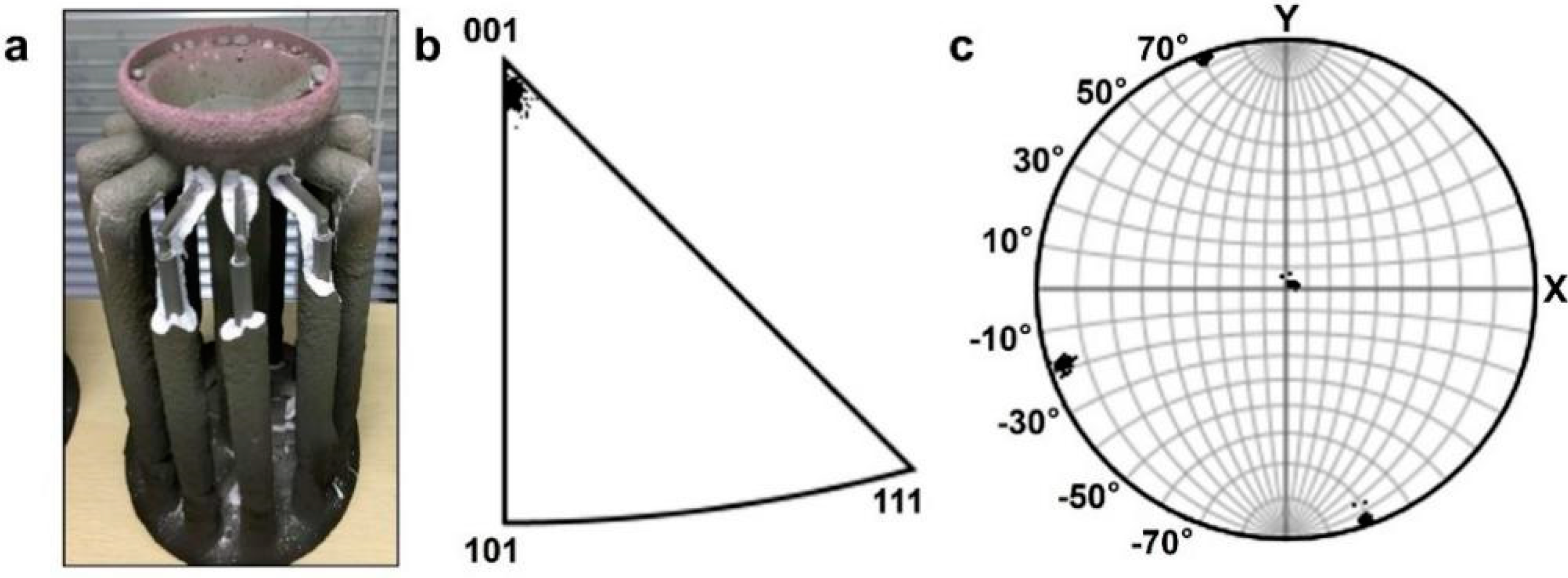
2.1.1. Single Crystal Growth

A typical second-generation Ni-based SX superalloy is selected to investigate microstructural evolution during single crystal growth, heat treatment, and mechanical testing. Table 1 lists the measured compositions of the selected alloy, which is close to those of the commercial superalloy DD6 [31]. Several well-studied Ni-based SX superalloys with similar compositions, including CMSX-4, 7, and 8, are also included in Table 1 for comparison [32,33,34]. Cylindrical rods with <001> orientation are directionally solidified to obtain single crystals by using the traditional Bridgman method, which is widely adopted for the growth of single crystal turbine blades or experimental rods. The details of single crystal growth can be found elsewhere [4]. The diameter of our experimental cylindrical rods is about 11 mm.

2.1.2. Heat Treatment

In order to design the solution heat treatment processes correctly, the phase transformation temperatures (e.g., γ′ solvus and melting temperatures) are measured by using the differential scanning calorimetry (DSC) technique. The DSC heating cycle is performed at a rate of 10 °C/min from room temperature (RT) to 1550 °C, using a Netzsch DSC 404 instrument (NETZSCH-GmbH, Germany) with an Ar flow of 20 mL/min.
The heat treatment experiments are carried out in a vacuum/Ar protected tube furnace, in which the heating rate, holding temperatures, and times can be program controlled. Before heating, the tube furnace is evacuated to a vacuum of <1 Pa and then followed by refilling with high purity argon. The evacuation and refilling processes repeat three times to reduce the impact of oxidation on the sample surfaces. The length of the hot zone and temperature of the furnace are routinely calibrated. The detailed heat treatment procedures are listed in Table 2.

2.2. Microstructural Characterization

Samples with a thickness of 1–2 mm are cut, and metallographically prepared to observe their microstructures. The metallographic procedure includes grinding down with 1200 grit SiC paper, followed by mechanical polishing. The final polishing media is a 40 nm colloidal silica suspension, which can effectively remove the damaged layer induced by the previous steps. To better reveal the microstructures, some of the polished samples are electrochemically etched in a 10% H3PO4 + H2O solution at 12 V at room temperature.
The secondary electron (SE) and backscattered electron (BSE) images, the energy dispersive spectroscopy (EDS) results, and the electron backscattered diffraction (EBSD) patterns are all captured in a FEI quanta 650 SEM (ThermoFisher, Waltham, MA, USA) equipped with Oxford EDS and EBSD detectors, using an accelerating voltage of 15 kV and a 10 mm working distance. Crystal orientations are determined by EBSD with the test area larger than 200 × 200 μm2.

2.3. Mechanical Testing

Dog bone-shaped tensile specimens with a gauge section of 3.1 × 1.0 × 12.5 mm3 are electro-discharge machined (EDM) from the SX rods after heat treatment. Before cutting, the SX rods are carefully reoriented to ensure that the tensile direction is [001], and other two side surfaces of the tensile plates are (100) and (010), respectively. All surfaces of the gauge section are carefully ground down with 800 grit SiC paper to eliminate micro-cracks that may be introduced by electro-discharge machining.
Tensile tests at room and elevated temperatures are conducted in air on a screw-driven mechanical testing machine equipped with an induction heater. A thermocouple, which is directly attached to the sample gauge section, is used to monitor testing temperature within ± 3 °C of the set temperature. All the specimens are tested at a constant displacement rate of 0.75 mm/min, which corresponds to an engineering strain rate of 1 × 10⁻³ s−1. Yield strengths are calculated using the 0.2% offset method.

3. Results and Discussion

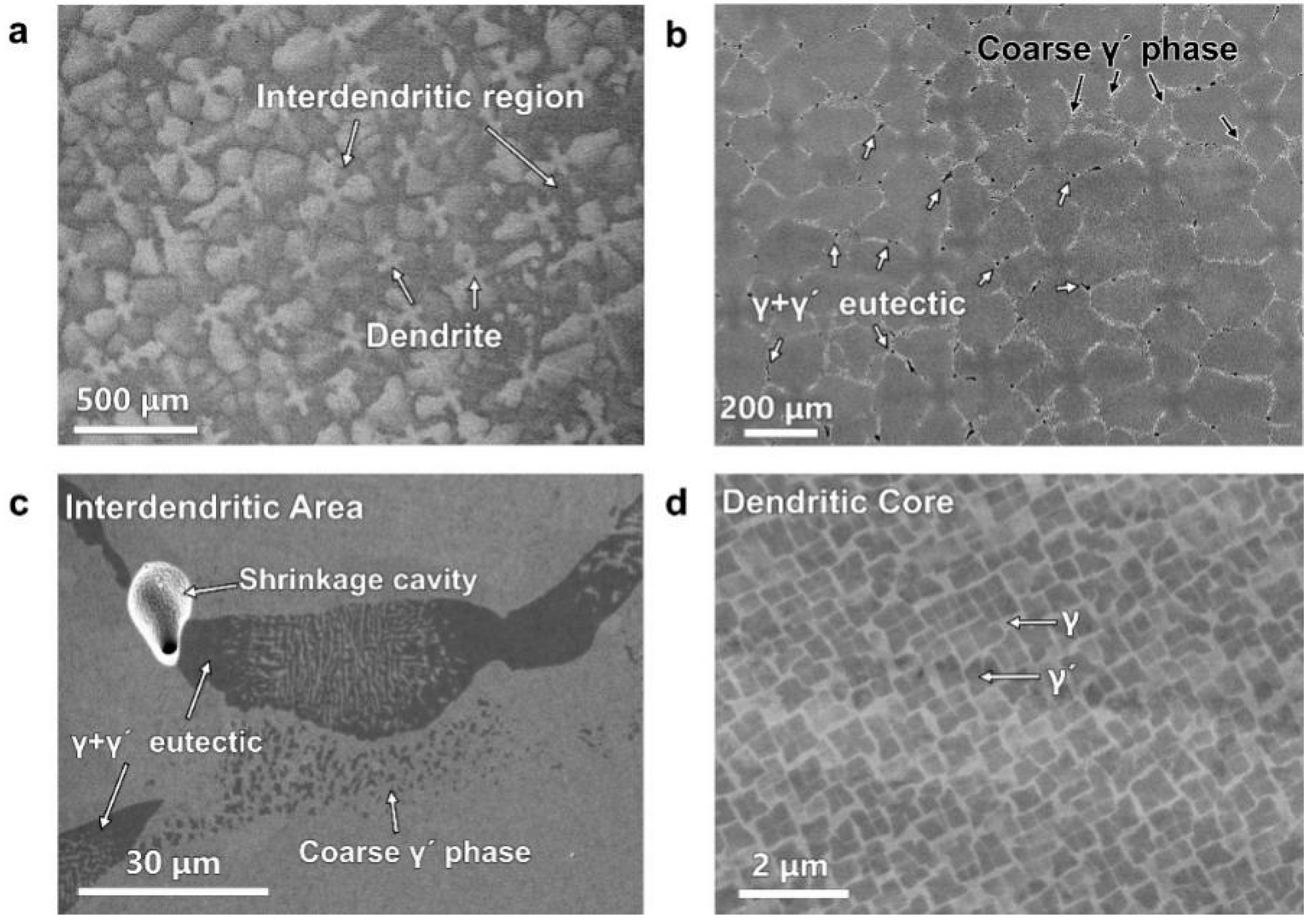
3.1. As-Grown Microstructure

The as-grown Ni-based single crystals right after growth are shown in Figure 1. After removing the ceramic mold, the rods are ready for further experiments. EBSDs are conducted to determine the orientation and the quality of single crystals. One example is shown as Figure 1b–c. The inverse (Figure 1b) and pole figures (Figure 1c) reveal that the growth direction is within 8° of the [001] direction, indicating a successful growth. Indeed, these rods are single crystals without high angle grain boundaries.
Figure 2 shows the as-gown microstructures of the selected superalloy, which are typical dendrite structures, resulting from compositional segregation during solidification. Under BSE imaging mode, four-leaf clover-shaped dendrites with a bright contrast can be clearly observed, and the interdendritic regions are relatively dark (Figure 2a). Because brightness is proportional to the averaged atomic number (Z) of the sample under BSE mode, high-Z elements (e.g, W, Re, etc.) may segregate at the dendrite arm. Therefore, EDS mapping is subsequently conducted to reveal the composition distribution at both dendrite and interdendritic regions, and the results are shown in Figure 3. It is found that the dendrite arms are rich in Re, W, and Mo, and the interdendritic regions are rich in Ta, Al, and Nb, while Cr, Co, and Ni are distributed relatively uniformly in both regions.
The elemental segregation results from the constitutional supercooling during solidification. It has been found that solute segregation occurs near the liquid–solid interface [12], and elements with higher melting points (W, Re, etc.) solidify earlier and then segregate at dendrites, while elements with lower melting points (Al) and those eutectic forming elements (Al, Nb, Ta, etc.) segregate at the interdendritic region. Consistent with this predication, there are coarse γ′ phases and eutectic microstructures observed in the interdendritic region (Figure 2b). The darker blocks (white arrows in Figure 2b) and the white dots (dark arrows in Figure 2b) are eutectic and coarse γ′ phases, respectively. In additions, a shrinkage cavity near eutectic phases is also frequently observed (Figure 2c), which may result from insufficient liquid at the latest stage of solidification. The microstructure of dendrite cores is relatively simple and homogeneous. A typical example is shown in Figure 2d, which consists of γ′ precipitates, with an average size of about 350 nm, uniformly distributed in the γ phase.

3.2. Heat Treatment

To eliminate the compositional and microstructural inhomogeneity, the as-grown alloy should be solid solution (SS) treated. Because the SS treatment is a solid-state transformation and is diffusion controlled, the principle of the temperature selection must be well above the temperature at which γ′ precipitates totally dissolve into the γ phase. Moreover, in the meantime, incipient melting must be avoided. In order to establish the heat treatment processes correctly, the phase transformation temperatures (e.g., γ′ solvus and melting temperatures) are determined from DSC measurements.
Figure 4 is a DSC heating curve of our alloy, and from this curve, the γ′ solvus temperature and incipient melting temperature of the as-grown single crystals can be determined as 1260 °C and 1350 °C, respectively. The SS temperature of the alloy should be above 1260 °C, but below 1350 °C, therefore, the range of 1280–1350 °C is defined as the SS window for our alloy.
Because the SS treatment is a diffusion-controlled process, higher temperatures and a longer processing time are needed to enhance the diffusion of solute elements. It is well known that increasing temperature rather than elongating the processing time is more efficient both in energy and the time needed for the heat treatment. However, the local inception of melting limits the highest temperatures that can be selected and the furnace capability becomes more critical at higher temperatures. With all those factors considered, eight stepwise SS heat treatments (see Table 2, designated as A–H) have been designed, and their corresponding microstructures are characterized.
As shown by the low-magnification BSE images in Figure 5, as the processing procedure varies from sample A to E (Figure 5a–e), the contrast of the dendrite arm decreases, and the shape of dendrites converts from four-leaf clover in sample A to the “+”shape in sample E. Meanwhile, the edge-contrast between dendrite arms and the interdendritic region is reduced, indicating that the stepwise heat treatment (HT) with a higher SS temperature and longer time is effective in alleviating the dendritic segregation. It is also found that in the final step above of 1330 °C/4 h + air cooling (AC) (sample E), a further increase in temperature by 10 or 20 °C (i.e., samples F–G) becomes less effective (Figure 5f,g). In sample H (final step of 1360 °C/4 h), the incipient melting has been found, as indicated by the white arrows in Figure 5h, which is consistent with the SS window obtained by DSC. Note that there are some black dots located at the interdendritic region in Figure 5a–h. These dots are probably shrinkage cavities, a solidification defect. Because SX superalloys are generally used in solidification plus heat treatment conditions, without thermomechanical processing, the shrinkage cavities normally exist inside the materials and might serve as initiation sites of failure during deformation. Minimizing the amounts and sizes of the shrinkage cavities during solidification should be an important research topic in future studies.
The ultimate goal of heat treatment is to obtain desirable two-phase γ/γ′ microstructures in such Ni-based superalloys. Besides the SS treatment, aging at a relatively low temperature is also required to obtain cuboid γ′ phases with appropriate sizes and with uniform distributions in the γ matrix. In order to better understand the effects of SS heat treatments on the final microstructures after the full cycle of heat treatment, samples A–G are also subjected to an aging treatment (1120 °C/4 h AC + 870 °C/24 h AC), as shown by their microstructural images in Figure 6. These aged samples are slightly etched so as to slightly remove the γ phase for better phase contrast under both SE and BSE imaging modes. Because both shrinkage cavities and eutectics are formed at the final stage of solidification in the interdendritic regions, the high magnification SEM images are focused on the microstructures of regions near shrinkage cavities and eutectics (Figure 6e–h). In the aged sample A, some residual eutectics and coarse γ′ phases still exist, indicated by white arrows in Figure 6a,e. In contrast, eutectics are not found in the other aged samples at low magnification, as shown in Figure 6b–d. However, a further high-magnification study of Figure 6b leads to the appearance of some residual eutectics in Figure 6f, especially in the interdendritic regions. Further increasing temperature to 1315 °C and above (Figure 6c,d,g,h), neither residual eutectics nor coarse phases is observed, even in high magnificent images (Figure 6g,h), therefore, it is concluded that the final SS treatment temperature need to be higher than 1315 °C.
The dendritic microstructural evolution, along with each step of SS heat treatment, can be used to justify the choice of processing temperatures and durations. The main purpose of step one (1290 °C/1 h) is to prevent temperature overshoot and dissolve γ′ precipitates. The second step (1300 °C/2 h) could effectively eliminate the majority of γ′ phases, including eutectics. The third step (1315 °C/2 h) further eliminates residual eutectics, thus improving the microstructural homogeneity. The aim of the subsequent heat treatments is to make alloying elements diffuse quickly and sufficiently to eliminate the elemental segregations to improve compositional homogeneity over the entire single crystal. Solid solution heat treatment is a diffusion-controlled process, so it is obvious that a slight increase in SS temperature and prolonged time maybe beneficial. Thus, a final mutli-step SS heat treatment protocol (1290 °C/1 h + 1300 °C/2 h + 1315 °C/2 h + 1325 °C/4 h + 1330 °C/4 h AC) is designed for our single crystals.
Furthermore, combined with the subsequent aging treatment (1120 °C/4 h AC + 870 °C/24 h AC), the desirable microstructures of a typical γ/γ′ two-phase structure are obtained (Figure 7). For a better illustration of the three-dimensional structure of γ′ precipitates, the γ phase has been selectively etched away, as shown in Figure 7b. Cuboid γ′ precipitates with an average size of ~400 nm are found to be distributed uniformly in the γ phase with the volume percentage of ~70%. In particular, the γ′ cubes are homogeneously distributed in both the previous dendrite arms and interdendritic regions, which make the entire sample have uniform microstructures. All the following mechanical testing specimens are subjected to the same newly designed heat treatment processes that lead to the microstructure in Figure 7.

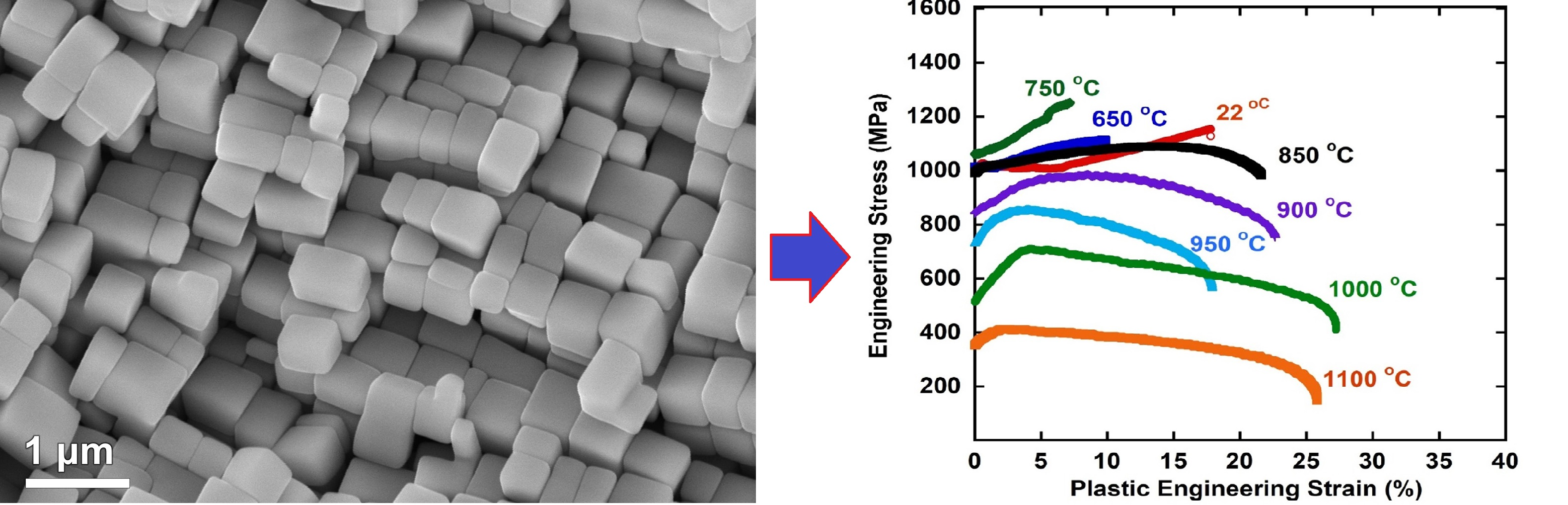
3.3. Tensile Properties

Tensile tests at room (RT) and various elevated temperatures are conducted to investigate the mechanical properties of our optimized superalloys with representative microstructures, as shown in Figure 7. The tensile loads are applied parallel to the [001] direction, which is the crystal growth direction. Other exposed surfaces of the tensile sample were (010) and (100) planes. Figure 8a shows the engineering stress–strain curves, and Figure 8b is a plot of the 0.2% off-set yield strength (YS) and ultimate tensile strength (UTS) as a function of the testing temperature.
When the testing temperature is below 750 °C, the samples fail after continuous work hardening. As the temperature increases to 750 °C from RT, YS and UTS both increase slightly (YS from 1010 to 1059 MPa, UTS from 1155 to 1253 MPa), and the elongation to failure decreases from 18% to ~7%. The strength increase from RT to 750 °C may be caused by the anomalous yielding effect of the L12 structured γ′ phase, which originated from the cross-slip of the anti-phase boundary (APB) from the {111} plane to the {001} plane and thus the formation of immobile Kear–Wilsdorf locks [35]. As cross-slip is thermally activated, the strength increases. This phenomenon in Ni-based single SX alloys is the so-called “intermediate temperature brittleness”.
When the temperature is above 850 °C, the alloy experiences a very short period of strain hardening (less than ~4% plastic strain) in the stress–strain curve, followed by strength drops as the strain increases. This might be associated with the occurrence of large scale cross-slip, which facilitates dislocation annihilation [36]. The reduction of the cross-sectional area would also result in the drop-off of the engineering stress–strain curve before failure. For example, the YS and UTS of the alloy at 1100 °C are 356 and 413 MPa, the stress continuously drops in the stress-strain curve after 413 MPa and the elongation to fracture is ~26%. In this temperature range, consistent with the reduction in the cross-sectional area, necking is normally observed. Overall, the tensile strength of our alloy is similar to the typical commercial CMSX-4 and DD6 alloys [32,37].

3.4. Fracture Analysis

Fracture analysis after the tensile testing was examined by SEM. Based on the fracture surface and microstructures near the fracture site, fracture modes can be divided into three groups, including low temperature (RT), intermediate temperatures (650–750 °C), and high temperatures (>850 °C). The microstructures of these samples fractured at RT, 650 °C, and 1100 °C are shown as examples in Figure 9, Figure 10 and Figure 11, respectively.
The fracture surface at RT shows some ductile features, and no significant necking occurs (Figure 9a,b), which is consistent with the fair ductility (18%) and the high work hardening (Figure 8a). A high density of zigzag slip traces along the {110} direction and ductile fracture features is clearly observed (Figure 9). High-magnification SEM images reveal a relatively brittle cleavage fracture in the γ′ cubes, but a narrow γ phase surrounding the γ′ cubes shows pull-out necking to a very sharp point, indicating that the γ phase is rather ductile (the inset of Figure 9a). Figure 9c shows the side view microstructure near the fracture surface. Rhomboid instead of rectangle shaped γ′ phases and shear traces through the γ′ cubes (red arrows) are clearly observed. All these observations indicate that at room temperature, the γ phase contributes most of the plasticity and the γ′ phase is relatively hard and brittle. The load partitioning in these two phases is responsible for the observed work hardening, and thus the less significant necking prior to ductile fracture.
As compared to the RT samples, the fracture surface at 650 °C is smoother and contains fewer shear traces (Figure 10a,b), indicating a reduced plasticity of the alloy at this temperature, which is consistent with the so-called “intermediate temperature brittleness” [38,39,40]. However, ductile dimples are still observed in the γ phases, similar to the fracture surface tested at RT (inset in Figure 10a), but the center of the γ′ phase is very smooth, indicating a cleavage fracture of the intermetallic phase. Additionally, little change from their original cuboidal shapes is observed in the γ′ phases near the fracture surface (Figure 10c). It can be concluded that γ′ phases have very little plasticity at this temperature. Fractures at intermediate temperatures may be caused by the rapid propagation of a crack at the initiation of shearing at an angle of about 45° to the tensile axis. The mechanism responsible for this shear band may be related to an increase in the strength ratio of these two phases, of which the validation requires an accurate measurement of the mechanical properties of individual phases.
As the testing temperature increases to 850 °C, the engineering stress first slightly increases (work hardening) and then continuously decreases until the sample fractures (Figure 8a), indicating the necking of the samples, consistent with the photograph of a necked sample (the inset of Figure 11a). Figure 11a also shows the low magnification side view BSE image of the fractured sample, in which bright dendrite cores are marked out by white arrows. It is obvious that there are a large amount of micro-voids in the interdendritic region after the sample fails, which indicates that failure starts from the interdendritic regions. Different from those at RT and intermediate temperature, slip/shear traces have not been observed, which indicates that deformation might be diffusional rather than slip plasticity. The γ/γ′ two-phase structure near the fracture surface is also completely different from the undeformed one. The γ′ phase has transformed from squares to elongated rounded rectangles, with the long axis along the tensile direction. Moreover, the γ phase perpendicular to the tensile direction become broader, and the γ phase parallel to the tensile direction shrinks, similar to the rafting microstructure during creep [29].
In principle, the γ′ phase is the predominant phase in volumes, and therefore appears to dominate the mechanical properties of the Ni-based SX superalloy. As a consequence, the fracture analysis in the present work shows that the γ phase is ductile at all testing temperatures, while the γ′ phase exhibits fair ductility at RT, limited ductility at intermediate temperatures (650–750 °C), and enhanced ductility at high temperatures (>850 °C).

4. Summary and Conclusions

To reveal the microstructural evolution of Ni-based SX superalloys during processing and to understand the processing–microstructure–property relationship, a second-generation Ni-based SX superalloy was successfully prepared by directional solidification along the [001] direction by using the Bridgman method. Based on microstructural observations, the main conclusions can be summarized as follows:
(1)
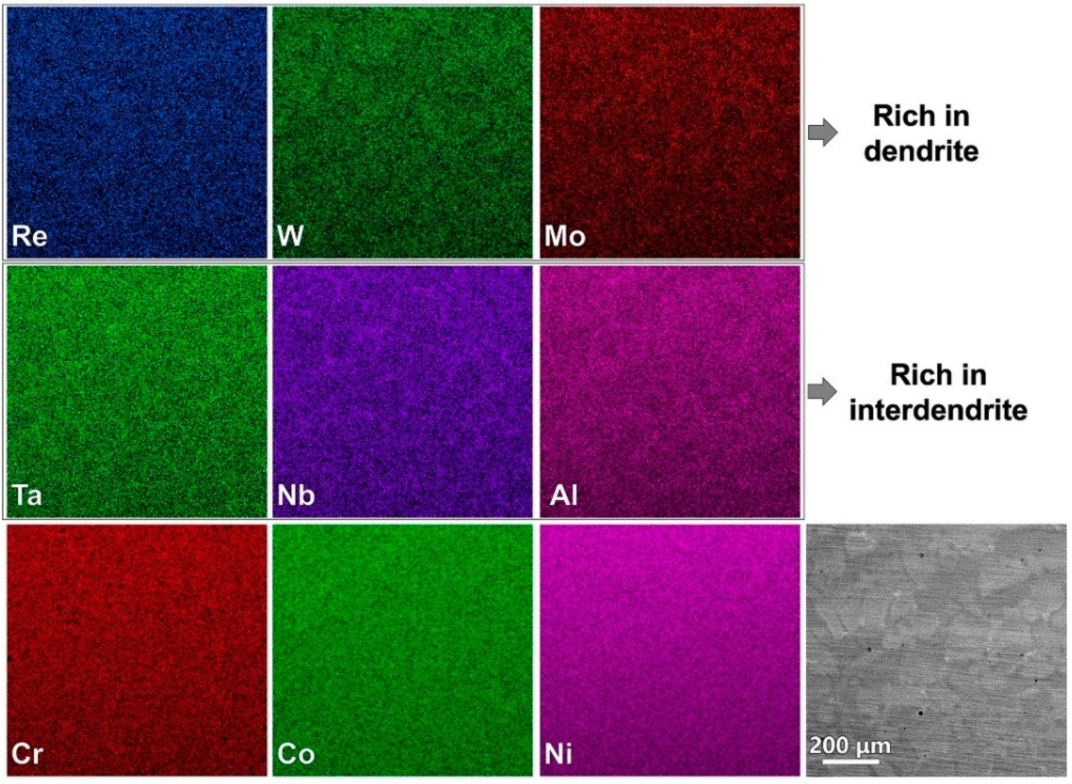
The as-grown microstructure is of a typical dendrite and there are significant compositional and microstructural differences between the dendritic arms and interdendritic regions. Refractory elements Re, W, and Mo segregate at the dendritic arms. Meanwhile, γ′-forming elements, as well as eutectic-forming elements (Al, Ta, Nb), segregate at the interdendritic region, resulting in coarse γ′ precipitates and eutectic microstructures.
(2)
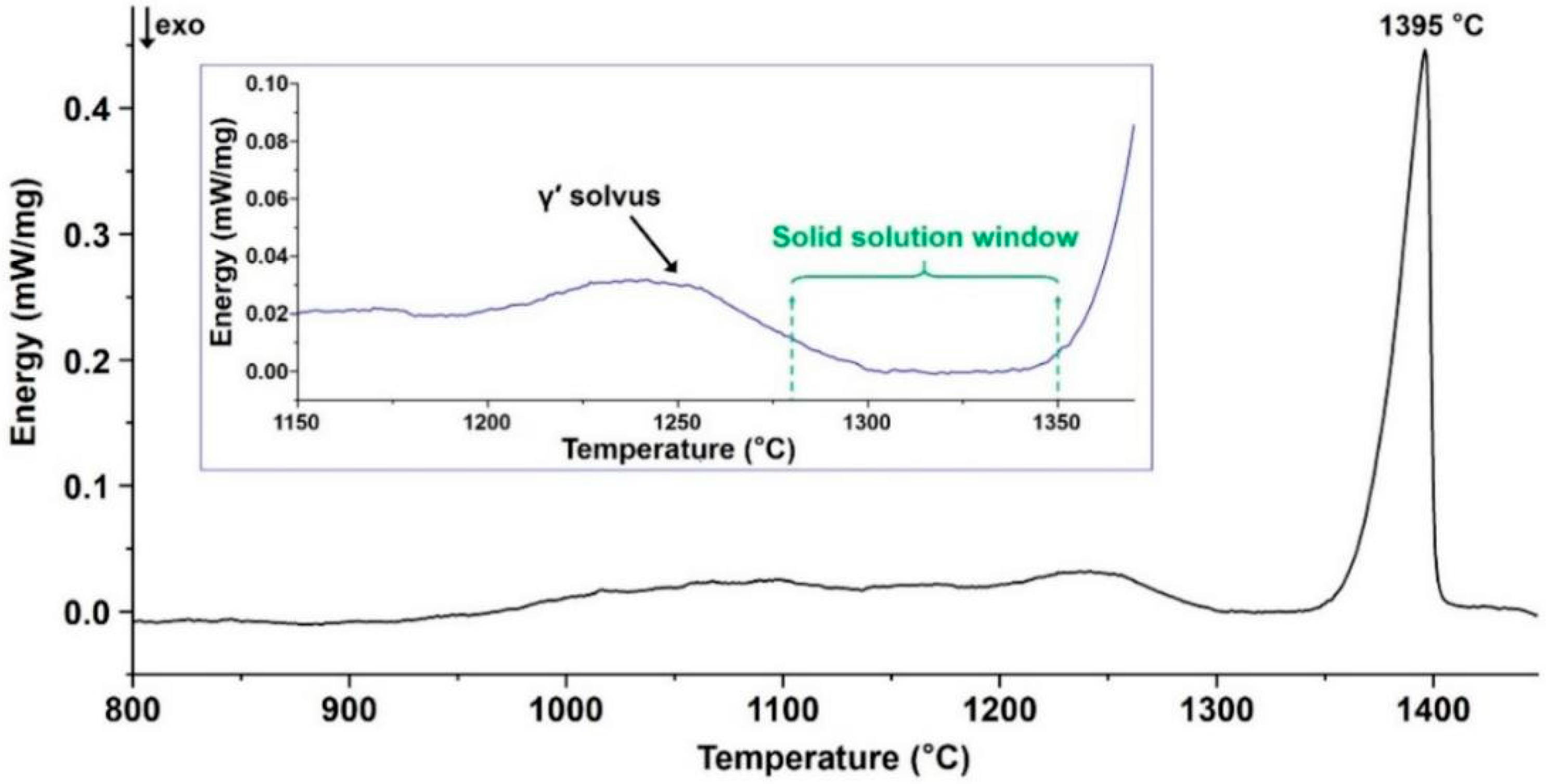
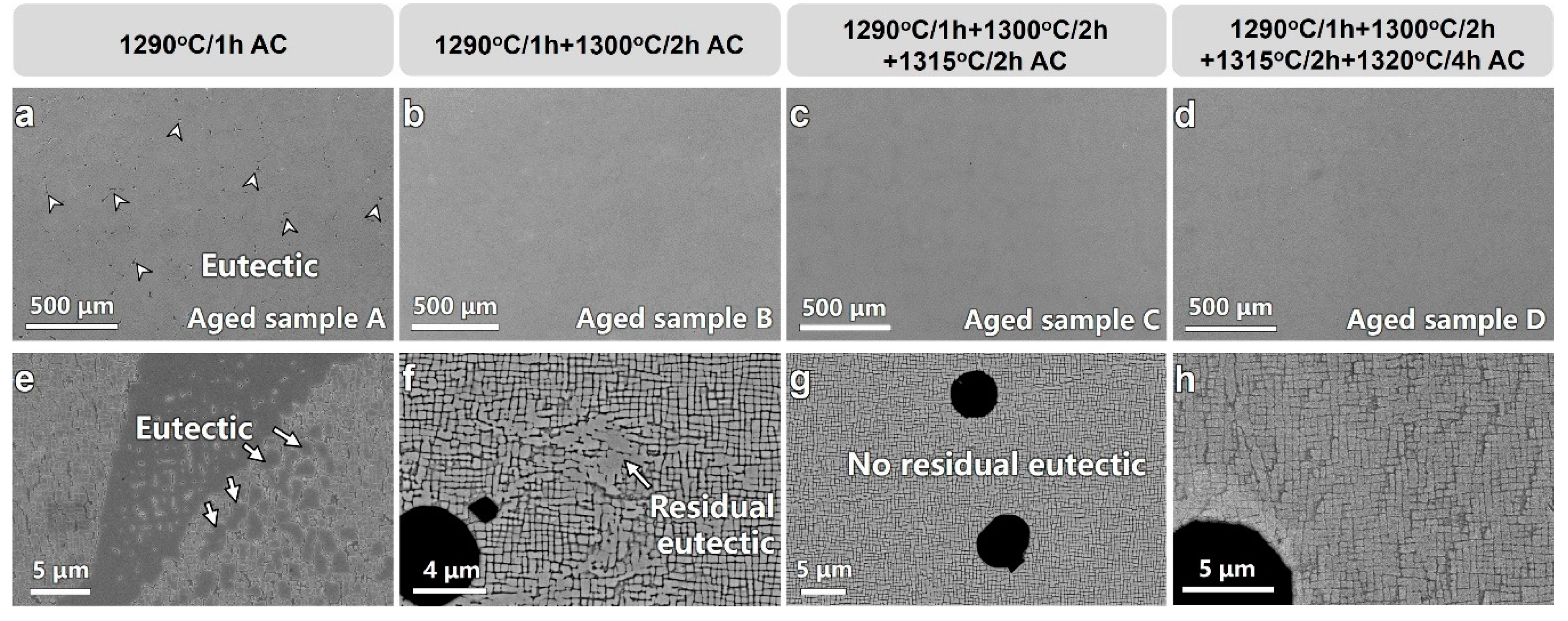
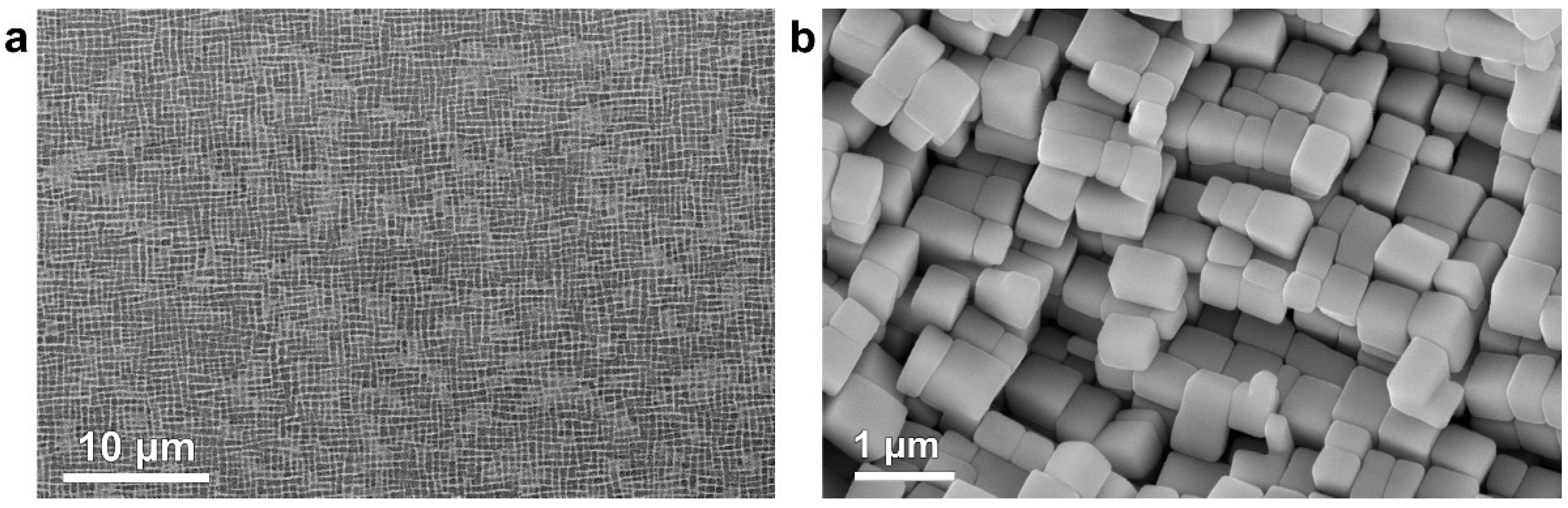
The solid solution treatment window has been determined to be 1280–1350 °C based on DSC results. A solution heat treatment procedure (1290 °C/1 h + 1300 °C/2 h + 1315 °C/2 h + 1325 °C/4 h + 1330 °C/4 h AC) has been identified to effectively eliminate eutectics at interdendritic regions and achieve compositional homogeneity without incipient melting. Combined with the subsequent aging heat treatment (1120 °C/4 h AC + 870 °C/24 h AC), homogeneous γ/γ′ two-phase structures (size of γ′ precipitate around 400 nm) have been obtained.
(3)
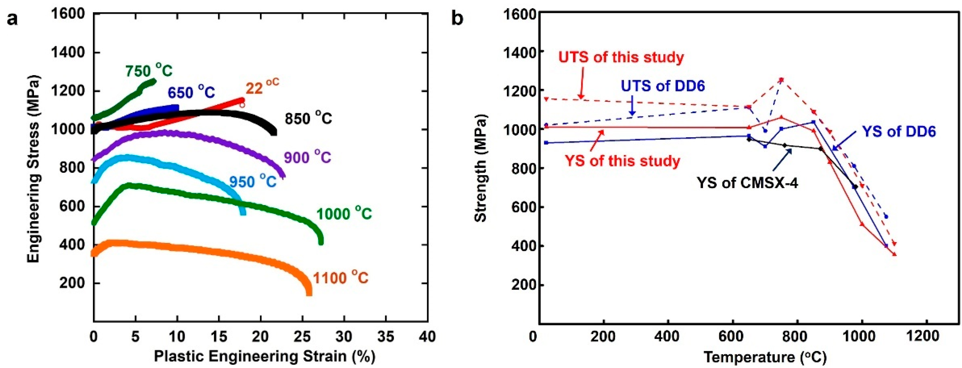
The tensile strength of our alloy is comparable to typical commercial CMSX-4 and DD6 alloys. The strength of the alloy increases with an increase in temperature from RT to 750 °C, 1059 MPa YS, and 1253 MPa UTS at 750 °C vs. 1010 MPa YS and 1155 MPa UTS at RT. Above this temperature, both YS and UTS decrease with the increase in temperature.
(4)
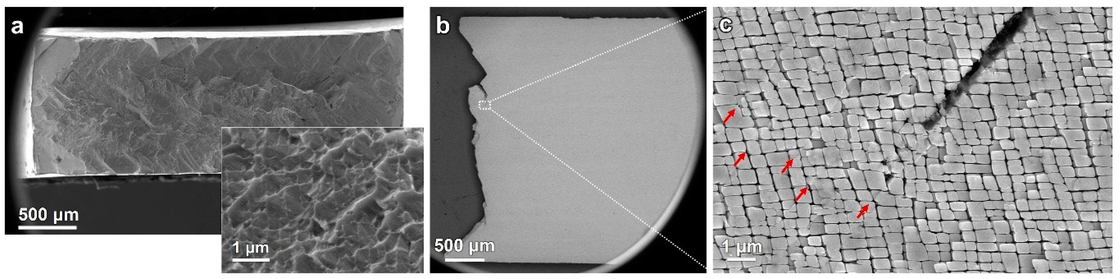
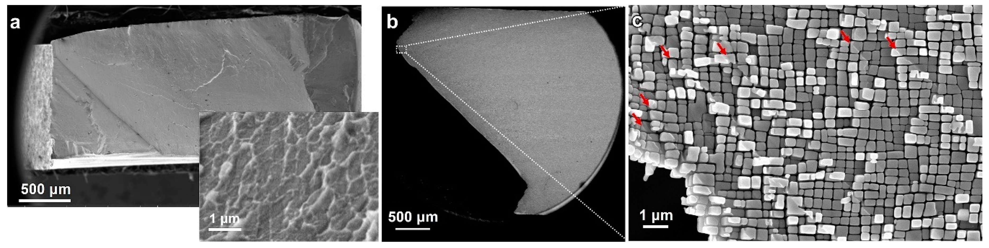
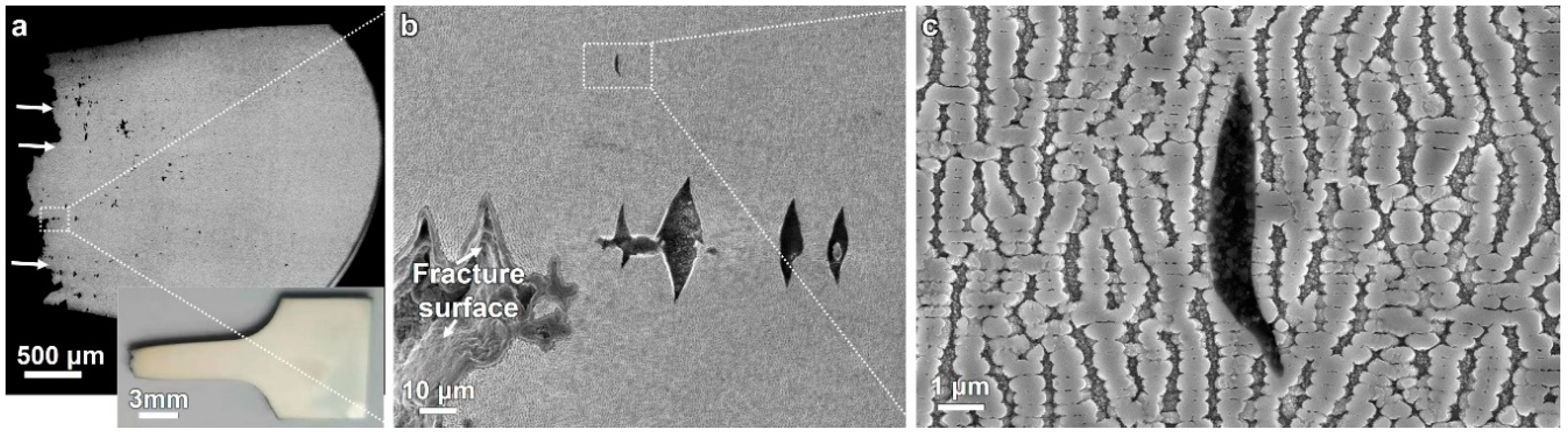
Subsequent fracture analysis demonstrates that the γ phase is ductile at all test temperatures but the γ′ phase appears to dominate the tensile properties. At RT, the γ′ phase exhibits a small degree of ductility, and the alloy fractures in a ductile manner. At intermediate temperatures, due to limited ductility of the γ′ phase, a rapid propagation of cracks by the shearing of the γ′ phase occurs, which is consistence with the “intermediate temperature brittleness” in Ni-based SX superalloys. At higher temperatures, necking occurs. Both the γ and γ′ phases become ductile, resulting in enhanced plastic deformation before fracture.

Author Contributions

Conceptualization, H.B. and Z.Z.; methodology, Q.D, H.B. and Y.G.; formal analysis, Q.D., H.B., X.Z., Y.G. and Z.Z.; resources, Z.Z.; data, Q.D. and H.B.; writing—original draft preparation, Q.D. and H.B.; writing—review and editing, Q.D., H.B., X.Z., Y.G. and Z.Z. All authors have read and agreed to the published version of the manuscript.

Funding

This work was supported by the Key R & D Project of Zhejiang Province (No. 2020C01002), Natural Science Foundation of Zhejiang Province (No. LQ20E01008), Basic Science Center Program for Multiphase Evolution in Hypergravity of the National Natural Science Foundation of China (No. 51988101), National Natural Science Foundation of China (No. 91960201), and Zhejiang Institute of Advanced Materials for Science and Innovation. YFG acknowledges the support from the US National Science Foundation (DMR 1809640).

Conflicts of Interest

The authors declare no conflict of interest.

References

  1. Reed, R.C. Superalloys: Fundamentals and Applications; Cambridge University Press: Cambridge, UK, 2006; pp. 1–28. [Google Scholar]
  2. Ru, Y.; Zhang, H.; Pei, Y.; Li, S.; Gong, S. Substitutng Mo for Re in equal weight for Ni based single crystal superalloy. Materialia 2019, 6, 100278. [Google Scholar] [CrossRef]
  3. Long, H.; Mao, S.; Liu, Y.; Zhang, Z.; Han, X. Microstructural and compositional design of Ni-based single crystalline superalloys—A review. J. Alloy. Compd. 2018, 743, 203–220. [Google Scholar] [CrossRef]
  4. Pollock, T.M. Alloy design for aircraft engines. Nat. Mater. 2016, 15, 809–815. [Google Scholar] [CrossRef]
  5. Erickson, G.L. The development and application of CMSX-10. In Superalloys 1996, Proceedings of the Eighth International Symposium on Superalloys, Seven Springs, PA, USA, 22–26 September 1996; Kissinger, R., Ed.; The Minerals, Metals & Materials Society: Warrendale, PA, USA, 1996; pp. 35–44. [Google Scholar]
  6. Petrushin, N.B.; Elyutin, E.S.; Visik, E.M.; Golynets, S.A. Development of a single-crystal fifth-generation nickel superalloy. Russ. Metall. 2017, 6, 38–51. [Google Scholar] [CrossRef]
  7. Kawagishi, K.; Yeh, A.C.; Yokokawa, T.; Kobayashi, T.; Koizumi, Y.; Harada, H. Development of an oxidation-resistant high-strength sith-generation single-crytal superalloy TMS-238. In Superalloys 2012, Proceedings of the Eighth International Symposium on Superalloys, Seven Springs, PA, USA, 9–13 September 2012; Huron, E.C., Reed, R.C., Eds.; Wiley: Hoboken, NJ, USA, 2012; pp. 189–195. [Google Scholar]
  8. Sato, A.; Harada, H.; Yeh, A.C.; Kawagishi, K.; Kobayashi, T.; Koizumi, Y.; Yokokawa, T.; Zhang, J.X. A 5th generation SC superalloy with balanced high temperature properties and processability. In Superalloys 2008, Proceedings of the Eleventh International Symposium on Superalloys, Champion, PA, USA, 14–18 September 2008; Reed, R.C., Green, K.A., Eds.; The Minerals, Metals & Materials Society: Warrendale, PA, USA, 2008; pp. 131–138. [Google Scholar]
  9. Ding, Q.; Lao, Z.; Wei, H.; Li, J.; Bei, H.; Zhang, Z. Site occupancy of alloying elements in γ′ phase of nickel-base single crystal superalloys. Intermetallics 2020, 161, 106772. [Google Scholar] [CrossRef]
  10. Liu, L.; Huang, T.W.; Zhang, J.; Fu, H.Z. Microstructure and stress rupture properties of single crystal superalloy CMSX-2 under high thermal gradient directional solidification. Mater. Lett. 2007, 61, 227–230. [Google Scholar] [CrossRef]
  11. Tian, S.G.; Xue, Y.C.; Zeng, Z. Influence of solution temperature on compositions segregation and creep behavior of a single crystal nickel-based superalloy. Mater. Sci. Forum 2013, 747, 690–696. [Google Scholar] [CrossRef]
  12. Kearsey, R.M.; Beddoes, J.C.; Jaansalu, K.M.; Thompson, W.T.; Au, P. The effects of Re, W and Ru on microsegregation behaviour in single crystal superalloy system. In Superalloys 2004, Proceedings of the Tenth International Symposium on Superalloys, Seven Springs, PA, USA, 19–23 September 2004; Green, K.A., Ed.; The Minerals, Metals & Materials Society: Warrendale, PA, USA, 2004; pp. 801–810. [Google Scholar]
  13. Seo, S.M.; Lee, J.H.; Yoo, Y.S.; Jo, C.Y.; Miyahara, H.; Ogi, K. Solute redistribution during planar and dendritic growth of directionally solidified Ni-based superalloy CMSX-10. In Superalloys 2008, Proceedings of the Eleventh International Symposium on Superalloys, Champion, PA, USA, 14–18 September 2008; Reed, R.C., Green, K.A., Eds.; The Minerals, Metals & Materials Society: Warrendale, PA, USA, 2008; pp. 277–286. [Google Scholar]
  14. Yu, Z.; Qiang, J.; Zhang, J.; Lin, L. Microstructure evolution during heat treatment of superalloys loaded with different amounts of carbon. J. Mater. Res. 2015, 30, 2064–2072. [Google Scholar] [CrossRef]
  15. Fuchs, G.E. Solution heat treatment response of a third generation single crystal Ni-based superalloy. Mater. Sci. Eng. A 2001, 300, 52–60. [Google Scholar] [CrossRef]
  16. Hegde, S.R.; Kearsey, R.M.; Beddoes, J. Design of solutionizing heat treatments for an experimental single crystal superalloy. In Superalloys 2008, Proceedings of the Eleventh International Symposium on Superalloys, Champion, PA, USA, 14–18 September 2008; Reed, R.C., Green, K.A., Eds.; The Minerals, Metals & Materials Society: Warrendale, PA, USA, 2008; pp. 301–310. [Google Scholar]
  17. Grosdidier, T.; Hazotte, A.; Simon, A. Precipition and dissolution processes in γ/γ′ single crystal nickel-based superalloys. Mater. Sci. Eng. A 1998, 256, 183–196. [Google Scholar] [CrossRef]
  18. Ren, W.; Niu, C.; Ding, B.; Zhong, Y.; Yu, J.; Ren, Z.; Liu, W.; Ren, L.; Liaw, P.K. Improvement in creep life of a nickel-based single-crystal superalloy via composition homogeneity on the multiscales by magnetic-field-assisted directional solidification. Sci. Rep. 2018, 8, 1452. [Google Scholar] [CrossRef] [PubMed] [Green Version]
  19. Hillier, G.S.; Bhadeshia, H.K.D.H. Homogenizaion of single crystal superalloys. In Perspectives in Metallurgical Development, Proceedings of the Centenary Conference, Sheffield, UK, 16–18 July 1984; Beech, J., Ed.; Metals Society: London, UK, 1984; pp. 183–187. [Google Scholar]
  20. Sluytman, J.S.V.; Pollock, T.M. Optimal precipitate shapes in nickel-base γ-γ′ alloys. Acta Mater. 2012, 60, 1771–1783. [Google Scholar] [CrossRef]
  21. Liu, J.; Yu, J.; Jin, T.; Sun, X.; Guan, H.; Hu, Z. Influence of temperature on tensile behavior and deformation mechanism of Re-containing single crystal superalloy. Trans. Nonferrous Met. Soc. China 2011, 21, 1518–1523. [Google Scholar] [CrossRef]
  22. Matuszewski, K.; Rettig, R.; Matysiak, H.; Peng, Z.; Povstugar, I.; Choi, P.; Müller, J.; Raabe, D.; Singer, R.F. Effect of ruthenium on the precipitation of topologically close packed phases in Ni-based superalloys of 3rd and 4th generation. Acta Mater. 2015, 95, 274–283. [Google Scholar] [CrossRef]
  23. Yang, J.X.; Zheng, Q.; Sun, X.F.; Guan, H.R.; Hu, Z.Q. Morphological evolution of γ′ phase in K465 superalloy during prolonged aging. Mater. Sci. Eng. A 2007, 457, 148–155. [Google Scholar] [CrossRef]
  24. Rae, C.M.F.; Reed, R.C. The precipitation of topologically close-packed phases in rhenium-containing superalloys. Acta Mater. 2001, 49, 4113–4125. [Google Scholar] [CrossRef]
  25. Huang, M.; Cheng, Z.; Xiong, J.; Li, J.; Hu, J.; Liu, Z.; Zhu, J. Coupling between Re segregation and γ/γ′ interfacial dislocation during high-temperature, low-stress creep of a nickel-based single-crystal superalloy. Acta Mater. 2014, 76, 294–305. [Google Scholar] [CrossRef]
  26. Garimell, L.; Liaw, P.K.; Klarstrom, D.L. Fatigue behavior in nickel-based superalloys: A literature review. J. Miner. Met. Mater. Soc. 1997, 49, 67. [Google Scholar] [CrossRef]
  27. Smith, T.M.; Unocic, R.R.; Deutchman, H.; Mills, M.J. Creep deformation mechanism mapping in nickel base disk superalloys. Mater. High. Temp. 2016, 33, 372–383. [Google Scholar] [CrossRef]
  28. Sulzer, S.; Reed, R. Critical assessment 31: On the modelling of tertiary creep in single-crystal superalloys. Mater. Sci. Technol. 2018, 34, 2174–2201. [Google Scholar] [CrossRef]
  29. Nabarro, F.R.N. Rafting in superalloys. Metall. Mater. Trans. A 1995, 27, 513–530. [Google Scholar] [CrossRef]
  30. Pollock, T.M.; Argon, A.S. Directional coarsening in nickel-base single crystals with high volume fractions of coherent precepitates. Acta Metall. et Mater. 1994, 42, 1859–1874. [Google Scholar] [CrossRef]
  31. Li, J.R.; Zhao, J.Q.; Liu, S.Z.; Han, M. Effects of low angle boundaries on the mechanical properties of single crystal superalloy DD6. In Superalloys 2008, Proceedings of the Eleventh International Symposium on Superalloys, Champion, PA, USA, 14–18 September 2008; Reed, R.C., Green, K.A., Eds.; The Minerals, Metals & Materials Society: Warrendale, PA, USA, 2008; pp. 443–450. [Google Scholar]
  32. Sengupta, A.; Putatunda, S.K.; Bartosiewicz, L.; Hangas, J.; Nailos, P.J.; Peputapeck, M.; Alberts, F.E. Tensile behavior of a new single-crystal nickel-based superalloy (CMSX-4) at room and elevated temperatures. J. Mater. Eng. Perform. 1994, 3, 73–81. [Google Scholar] [CrossRef]
  33. Wahl, J.; Harris, K. New single crystal suprealloys, CMSX-7 and CMSX-8. In Superalloys 2012, Proceedings of the Eighth International Symposium on Superalloys, Seven Springs, PA, USA, 9–13 September 2012; Huron, E.C., Reed, R.C., Eds.; Wiley: Hoboken, NJ, USA, 2012; pp. 177–188. [Google Scholar]
  34. Elliott, A.J.; Pollock, T.M. Thermal analysis of the Bridgman and liquid-metal-cooled directional solidification investment casting processes. Metall. Mater. Trans. A 2007, 38, 871–882. [Google Scholar] [CrossRef]
  35. Reed, R.C. The Superalloys: Fundamentals and Applications; Cambridge University Press: New York, NY, USA, 2006; pp. 81–90. [Google Scholar]
  36. Dieter, G.E. Mechanical Metallurgy; McGraw-Hill Book Company: New York, NY, USA, 1961; pp. 110–117. [Google Scholar]
  37. Li, J.R.; Zhong, Z.G.; Tang, D.Z.; Liu, S.Z.; Wei, P.; Wei, P.Y.; Wu, Z.T.; Huang, D.; Han, M. A low-cost second generation single crystal superalloy DD6. In Superalloys 2000, Proceedings of the Ninth International Symposium on Superalloys, Champion, PA, USA, 17–21 September 2000; Green, K.A., Pollock, T.M., Kissinger, R., Eds.; The Minerals, Metals & Materials Society: Warrendale, PA, USA, 2000; pp. 777–783. [Google Scholar]
  38. Veyssière, P.; Saada, G. Chapter 53 Microscopy and plasticity of the L12 γ′ phase. Dislocations Solids 1995, 10, 253–441. [Google Scholar]
  39. Rentenberger, C.; Karnthaler, H.P. The stability of screw dipoles in Ni3Al studied by TEM. Intermetallics 2008, 16, 571–579. [Google Scholar] [CrossRef]
  40. Rentenberger, C.; Karnthale, H.P. TEM study of the friction stress acting on edge dislocations in Ni3Al. Intermetallics 2003, 11, 601–609. [Google Scholar] [CrossRef]
Figure 1. (a) Photograph of the single crystal (SX) rods in the mold. Inverse pole figure (b) and pole figure (c) obtained from one of the SX rods in (a), indicating that the crystal growth direction is along the [001] direction.
Crystals 10 00572 g001
Figure 2. The cross-sectional microstructures of the as-grown Ni-based single crystal (SX) superalloy. (a) Backscattered electron (BSE) image showing the dendrite structure. Segregation of high-Z elements results in a bright contrast in the dendrite arm and dark contrast in the interdendritic region. (b) Secondary electron (SE) image showing the distribution of eutectics and coarse γ′ phases at the interdendritic region. (c,d) Typical microstructures of interdendritic and dendritic core regions, respectively.
Crystals 10 00572 g002
Figure 3. Energy dispersive spectroscopy (EDS) maps showing element distribution in an as-grown Ni-based single crystal superalloy. Refractory elements Re, W, and Mo segregate at dendrite arms, while Ta, Al, and Nb segregate at interdendritic regions.
Crystals 10 00572 g003
Figure 4. Differential scanning calorimetry (DSC) profile of the as grown Ni-based single crystal superalloy. The inset is a zoom-in of the curve showing details of the solid solution window.
Crystals 10 00572 g004
Figure 5. Dendritic segregation in samples after different solid solution heat treatments (i.e., Table 2). (ah) The contrast of the dendrite arm decreases as the solution treatment temperature and time increase; (h) Incipient melting is clearly observed at temperature of 1360 °C. The heat treatment detail of each sample is shown at the top of each backscattered electron (BSE) image. Note that black dots are shrinkage cavities.
Crystals 10 00572 g005
Figure 6. Effects of solid solution (SS) processing on the microstructures after aging at 1120 °C/4 h air cooling (AC) + 870 °C/24 h AC (ad) low magnificent secondary electron (SE) images showing overall microstructures after a full cycle of SS and aging heat treatment; (eh) The corresponding high-magnification images showing microstructures in the interdendritic region of (ad). There are clearly residual eutectics/coarse γ′ phases in (ef), but not in (gh).
Crystals 10 00572 g006
Figure 7. Micrographs showing a typical γ/γ′ two-phase structure. (a) Low magnification backscattered electron (BSE) image showing that the microstructure is uniform; (b) three-dimensional structure of γ′ precipitates in Ni-based single crystal superalloy.
Crystals 10 00572 g007
Figure 8. Tensile properties of the Ni-based single crystal (SX) superalloy at different temperatures. (a) Engineering stress–strain curves. (b) Yield strength (YS) and ultimate tensile strength (UTS) of the tested alloy and other second-generation Ni-based SX superalloys. Data of DD6 and CMSX-4 are taken from [32,37].
Crystals 10 00572 g008
Figure 9. Fracture analysis after the tensile test at room temperature. (a) Both low and high magnification images showing the ductile nature of the fracture mode. The loading direction is out of plane. (b) Side view of the fractured sample. (c) Magnified image near the fracture surface, as indicated by the white dashed rectangle in (b), the red arrows in (c) showing the shear traces in the sample surfaces, with the loading direction is horizontal.
Crystals 10 00572 g009
Figure 10. Fracture analysis after tensile testing at 650 °C. (a) Fracture surface of the sample, whose zoomed in image is shown in the inset. The loading direction is out of plane. (b) Side view of the fractured sample. (c) Magnified microstructure near the fracture surface, captured from the white dashed rectangle in (b). The loading direction is horizontal.
Crystals 10 00572 g010
Figure 11. Fracture analysis after the tensile test at 1100 °C. (a) Side view of fractured sample (Backscattered electron image). The inset is an optical photograph of the necked sample. (b) Micro-cracks in the interdendritic region near fracture surface, captured from the area marked out by white dashed rectangle in (a). (c) Magnified microstructure near the fracture surface, obtained from the white rectangle in (b). The loading direction is horizontal in all images.
Crystals 10 00572 g011
Table 1. Measured composition (wt.%) of our alloy in this study and nominal composition of some other second-generation Ni-based single crystal superalloys.
AlloysCrCoMoWTaReNbAlTiHfNiReference
Our alloy4.28.82.29.08.02.30.55.1 0.1Bal.
DD64.39.02.08.07.52.00.55.6 0.1Bal.[31]
CMSX-46.590.666.53-5.610.1Bal.[32]
CMSX-76100.69.09.0--5.70.80.2Bal.[33]
CMSX-85.4100.68.081.5-5.70.70.1Bal.[34]
Table 2. Stepwise solid solution heat treatment procedures, as designed in this study.
SampleHeat Treatment
A1290 °C/1 h air cooling (AC)
B1290 °C/1 h + 1300 °C/2 h AC
C1290 °C/1 h + 1300 °C/2 h + 1315 °C/2 h AC
D1290 °C/1 h + 1300 °C/2 h + 1315 °C/2 h + 1320 °C/4 h AC
E1290 °C/1 h + 1300 °C/2 h + 1315 °C/2 h + 1330 °C/4 h AC
F1290 °C/1 h + 1300 °C/2 h + 1315 °C/2 h + 1340 °C/4 h AC
G1290 °C/1 h + 1300 °C/2 h + 1315 °C/2 h + 1350 °C/4 h AC
H1290 °C/1 h + 1300 °C/2 h + 1315 °C/2 h + 1360 °C/4 h AC

