Article

Highly Crystalline TiO2-MoO3 Composite Materials Synthesized via a Template-Assisted Microwave Method for Electrochemical Application

by
Adam Kubiak
1,
Wiktoria Wojciechowska
1,
Beata Kurc
2,
Marita Pigłowska
2,
Karol Synoradzki
3,4,5,
Elżbieta Gabała
6,
Dariusz Moszyński
7,
Mirosław Szybowicz
8,
Katarzyna Siwińska-Ciesielczyk
1 and
Teofil Jesionowski
1,*
1
Faculty of Chemical Technology, Institute of Chemical Technology and Engineering, Poznan University of Technology, Berdychowo 4, PL-60965 Poznan, Poland
2
Faculty of Chemical Technology, Institute of Chemistry and Electrochemistry, Poznan University of Technology, Berdychowo 4, PL-60965 Poznan, Poland
3
Polish Academy of Sciences, Institute of Molecular Physics, Mariana Smoluchowskiego 17, PL-60179 Poznan, Poland
4
Polish Academy of Sciences, Institute of Low Temperature and Structure Research, Okólna 2, PL-50422 Wroclaw, Poland
5
NanoBioMedical Centre, Adam Mickiewicz University, Poznan, Wszechnicy Piastowskiej 3, PL-61614 Poznan, Poland
6
National Research Institute, Institute of Plant Protection, Węgorka 20, PL-60318 Poznan, Poland
7
Faculty of Chemical Technology and Engineering, Department of Inorganic Chemical Technology and Environment Engineering, West Pomeranian University of Technology in Szczecin, Piastów 42, PL-71065 Szczecin, Poland
8
Faculty of Materials Engineering and Technical Physics, Poznan University of Technology, Piotrowo 3, PL-60965 Poznan, Poland
*
Author to whom correspondence should be addressed.
Crystals 2020, 10(6), 493; https://doi.org/10.3390/cryst10060493
Submission received: 27 April 2020 / Revised: 27 May 2020 / Accepted: 4 June 2020 / Published: 8 June 2020
(This article belongs to the Section Hybrid and Composite Crystalline Materials)

Abstract

:
TiO2-MoO3 composite systems were successfully prepared using a template-assisted microwave method at molar ratios TiO2:MoO3 = 8:2, 5:5 and 2:8. The synthesized material systems were comprehensively characterized, in terms of their crystalline structure (XRD and Raman spectroscopy), morphology (SEM, TEM and HRTEM analysis) and parameters of the porous structure (low-temperature N2 sorption). The materials exhibited highly crystalline phases: anatase and hexagonal molybdenum trioxide. Moreover, TEM analysis revealed hexagonal prism particles of MoO3 and nanocrystalline particles of TiO2. The proposed template-assisted microwave synthesis enabled the incorporation of TiO2 particles on the surface of hexagonal particles of MoO3, which resulted in a stable junction between titania and molybdenum trioxide. The values of BET surface area were 57, 29 and 11 m2/g for samples obtained at molar ratios TiO2:MoO3 = 8:2, 5:5 and 2:8 respectively. In electrochemical applications, titanium dioxide plays a crucial role as an intercalation intensifier, in which MoO3 is responsible for current conduction. Taking account of the potential electrochemical applications, the best system was obtained at the molar ratio TiO2:MoO3 = 5:5. The anode could maintain a capacity of 400 mAh/g at current densities in the range 100–1000 mA/g at potential values ranging from 1.00 to 3.30 V vs. Li/Li+. X-ray photoelectron spectroscopy (XPS) confirmed the effective intercalation of lithium ions into the TiO2-MoO3 composite materials.

1. Introduction

In recent years there has been a significant increase in the popularity of devices powered by lithium-ion batteries (LIBs), due to the need for constant communication and access to information [1]. With the development of mobile devices, new technologies are needed to make energy management more efficient, because the battery is essential for the reliability of such devices. Lithium-ion batteries are the most commonly used reversible cells. To make them suitable for wider use in home, mobile or even automotive devices, batteries should possess certain features: a high number of charge/discharge cycles and long service life, operability over a wide temperature range, safety during use, etc. [2,3]. Electrochemical reversible cells appear to be the most effective among all energy storage devices [4], therefore there is still much ongoing research aimed at improving them. It is valuable to focus on the reduction of production costs, which are relatively high and generate large amounts of waste [5], because lithium-ion cells themselves are a promising replacement for internal combustion engines [6]. They do not emit harmful exhaust gases, which means that they meet the regulations on emission reduction and may contribute to the reduction of greenhouse gas emissions [7,8]. The cells may pose a danger in case of overheating, over-rapid charging [9] or overcharging [10], because in such situations uncontrolled rupture (due to pressure increase) may occur, possibly resulting in an explosion or fire due to the presence of a flammable electrolyte [9,11].
To improve lithium-ion cells, it is necessary to search for new electrode materials, as these determine the cells functional parameters [10]. Depending on the material used, it is possible to adjust power, cell capacity and working safety. To improve performance, transition metal oxides have been tested in this function. They have proved to be an interesting anode material due to their low electrical resistance, high chemical stability and good theoretical capacity [12,13]. Molybdenum trioxide [14,15] appears particularly promising; however, many problems associated with the poor kinetics of Li+ ion diffusion [16] in the MoO3 mass have been observed during research. Therefore, to improve the electrochemical properties, various morphological forms of molybdenum trioxide have been studied, including nanofibers [15] and nanorods [16]. Another approach is to create MoO3 systems together with another oxide [17]. Due to the combination of various physical and electrochemical properties of the components, it is possible to increase the efficiency and usability of such systems. The combination of molybdenum trioxide with titanium dioxide [18] may be an interesting composite material in electrochemistry, since titanium dioxide is easily available and safe, and ensures long-term stability [19,20]. Its disadvantage is the poor conductivity and low diffusion rate of Li+, hence its combination with MoO3 may be a solution to this problem. Furthermore, it should be noted that in the case of titanium dioxide an intercalation/deintercalation mechanism can be proposed based on the available literature [21,22], this type of material being classified as an intercalation anode. Molybdenum trioxide is described as a conversion anode [23].
The synthesis of TiO2-MoO3 composite materials has already been the subject of research. Wang et al. [24] obtained a novel synergistic TiO2-MoO3 core-shell nanowire array for application as an anode material, via hydrothermal synthesis and a controlled electroplating process. The oxide system fabricated with a mass ratio of 1:1 was found to have a high gravimetric capacity, almost equal to the theoretical value of the TiO2-MoO3 materials. Xie et al. [25] obtained a coaxial TiO2/MoO3@CNF material using electrospinning and annealing. The product exhibited excellent lithium storage efficiency; after 300 cycles it had a return capacity of 561 mAh/g at 1000 mA/g. Beside the electrochemical properties of the above-mentioned materials, Li et al. [26] noted that TiO2-MoO3 core-shell materials synthesized via a one-step hydrothermal process offered improved photochromic properties. Furthermore, Liu et al. [27] drew attention to the photocatalytic activity of the TiO2-MoO3 heterostructure. Liu et al. [28] applied TiO2-MoO3 composites in the oxidative dehydrogenation of lactic acid to pyruvic acid and demonstrated a strong synergistic effect between the MoO3 and TiO2 components of the mixed oxide catalyst.
The available scientific literature shows that TiO2-MoO3 materials have many potential applications, in areas such as photocatalysis, electrochemistry and dehydrogenation processes. However, in many cases researchers have indicated that the designed morphology is a crucial parameter determining future uses of the materials. Therefore, in [25,26] the hydrothermal and electrospinning methods were used, which make it possible to obtain materials with a specified morphology. On the other hand, one of the significant disadvantages of hydrothermal treatment is the time of the process, and hence the high energy consumption. Therefore, the use of microwave irradiation in the hydrothermal process enables the further development of this synthesis technique. The many advantages of microwave-assisted synthesis over other conventional synthesis methods include rapid and uniform heating, energy savings, higher yield, shorter time of preparation, lower processing cost and the ability to obtain products with narrow particle size distributions [29]. Moreover, Roberts and Strauss [30] found that microwave synthesis may be an element of a broad strategy for environmentally friendly processing. On the other hand, although the microwave method is a very efficient technique for the production of many type of nanomaterials, it is still in the early stages of development, and further research is required to understand the mechanism of the impact of microwaves on the physicochemical properties of synthesized products [31,32]. Microwaves can cause instantaneous as well as steady-state differences in temperature on reactor scales, which must be explained before the design of an industrial microwave reactor [32,33].
The above considerations provided the motivation for the present study, in which titanium dioxide and molybdenum trioxide were combined into composite systems using a template-assisted microwave method. The obtained composite materials exhibited highly crystalline phases: anatase and hexagonal molybdenum trioxide. The values of the BET surface area were 57, 29 and 11 m2/g for samples obtained at molar ratios TiO2:MoO3 = 8:2, 5:5 and 2:8 respectively. Moreover, the incorporation of nanocrystalline particles of TiO2 on the highly crystalline hexagonal MoO3 particles was observed, which improved the electrochemical properties of the synthesized materials. Consequently, the use of TiO2-MoO3 material at different current densities and over many cycles produced favorable results, confirming the promise of this type of materials for use in lithium-ion cells.

2. Materials and Methods

2.1. Materials

Titanium(IV) chloride (97%), ammonium heptamolybdate tetrahydrate (99%), Pluronic® P123 (PEG-PPG-PEG Mn~5800), hydrochloric acid (36.5–38%), lithium foil (0.75 mm thick), ammonium hydroxide (25%) and ethanol (99%) were purchased from Sigma-Aldrich (USA). Acetylene black (AB), poly(vinylidene fluoride) (PVdF, MW = 180,000), N-methyl-2-pyrrolidinone (NMP), MoO3, lithium hexafluorophosphate (LiPF6), ethylene carbonate (EC) and dimethyl carbonate (DMC) were purchased from Fluka. All reagents were of analytical grade and used without any further purification. The water used in all experiments was deionized.

2.2. Preparation of TiO2-MoO3 Composite Systems

To obtain TiO2-MoO3 composite systems, a two-step microwave synthesis was used. In the first stage, 100 cm3 of 10% titanium (IV) chloride solution was added to a reactor equipped with a magnetic stirrer (IKA Werke, Staufen, Germany). Then, at a dosing rate of 5 cm3/min, an appropriate amount of ammonium hydroxide was added until the pH reached 10. In the next step, the obtained reaction mixture was subjected to microwave treatment at 180 °C for 15 min with a power of 300 W (SP-D 80, CEM, Matthews, USA). The obtained titanium dioxide was filtered, washed three times with deionized water and dried at 105 °C for 12 h.
Subsequently, the synthesis of TiO2-MoO3 composite systems was carried out. A reactor containing 25 cm3 of a 10% solution of ammonium heptamolybdate was placed above a magnetic stirrer (IKA Werke, Staufen, Germany). Next, 3 M HCl was dosed into the reactor at a rate of 5 cm3/min until the pH decreased to 1. Pluronic P123 was used to incorporate titanium dioxide nanoparticles into the hexagonal structure of molybdenum trioxide. Pluronic® P123 (2 g) was dissolved in 25 cm3 of ethanol, then added to the solution of MoO3 precursor and mixed for 10 min. An appropriate amount (Table 1) of the titanium dioxide prepared in the first step was sonicated for 10 min, then added to the reaction mixture and stirred for 10 min. Finally, the obtained mixture was subjected to microwave treatment at 140 °C for 15 min with a power of 300 W (SP-D 80, CEM, Matthews, USA). The synthesized composite systems were filtered, washed three times with deionized water and dried at 70 °C for 7 h. Composite materials were synthesized at TiO2:MoO3 molar ratios of 8:2, 5:5 and 2:8, labeled as Ti8Mo2, Ti5Mo5 and Ti2Mo8 respectively. Additionally, reference TiO2 and MoO3 samples were prepared. The quantities of substrates used for the synthesis of TiO2-MoO3 composite systems are given in Table 1.

2.3. Characterization of Obtained Materials

The X-ray diffraction (XRD) method was used to determine the crystalline structure of the synthesized materials. A Rigaku Miniflex 600 (Rigaku, Tokyo, Japan) diffractometer operating with Cu Kα radiation (λ = 1.5418 Å) was used. Patterns were obtained over an angular range of 10–80°. XRD data were analyzed using the Rietveld refinement method using the Fullprof program [34]. The crystallite size of the synthesized materials was determined using the Williamson-Hall method [35], represented by the Equation (1):
β cos θ = K λ D + 4 ε sin θ
where β is the line broadening at half the maximum intensity (FWHM), θ is the Bragg angle, K is a shape factor (0.891), D is the crystallite size, λ is the X-ray wavelength, and ε is the lattice strain.
Nonpolarized Raman spectra were recorded in the spectral range of 100–1200 cm−1, in the backscattering geometry, using the confocal inVia Renishaw micro-Raman system. Excitation light of 488 nm from a tunable Ar-ion laser was used. A Leica50x long working distance microscope objective (LWD) with a numerical aperture (NA) of 0.5 enabled the focusing of the laser beam to a diameter of approx. 2 μm on the sample surface, with a spectral resolution of approx. 2 cm−1. During measurements, the excitation of the laser power was fixed at approximately 5 mW to minimize sample degradation or sample heating. Both data collection and deconvolution of the obtained spectra using the curve fitting method were performed using Renishaw WiRE 3.4 (Reinshaw, Wesemann Dundee, USA) software. For the curve fitting procedure, a mix of Lorentz and Gauss functions was used to obtain spectral parameters such as wavenumber bands.
To determine the morphology and microstructure of the obtained materials, an EVO40 scanning electron microscope (Zeiss, Munich, Germany) was used. Next, a Hitachi HT7700 (Hitachi, Tokyo, Japan) transmission electron microscope working in high contrast (HC) and high resolution (HR) mode was applied. The microscope operated at 100 kV.
The textural properties of the materials based on titania and molybdenum trioxide were determined using an ASAP 2020 physisorption analyzer (Micromeritics Instrument Co., Norcross, GA, USA). The analyzer determines the Brunauer-Emmett-Teller (BET) surface area, total pore volume and pore size, applying low-temperature N2 sorption. Before measurement, the analyzed materials were degassed at 120 °C for 4 h. The surface area was determined using the multipoint BET method using adsorption data for relative pressure (p/p0) in the range 0.05–0.30.
X-ray photoelectron spectra were obtained using Mg Ka (hυ = 1253.7 eV) radiation with a Prevac system equipped with a Scienta SES 2002 (Prevac, Rogow, Poland) electron energy analyzer operating at constant transmission energy (Ep = 50 eV). The base pressure was kept below 1 × 10⁻⁹ mbar. The samples were attached to the molybdenum sample holder by means of a double-sided adhesive tape. The binding energy scale of XPS figures was corrected due to charging. Since there was no common reference species for all samples, two anchors were utilized. The binding energy scale for the Ti5Mo5 electrodes was set at BE = 291.0 eV for the C 1s peak component ascribed to (CH2-CF2) groups from PVdF, and scales for other elements were corrected accordingly. The binding energy scales for the Ti5Mo5 sample were corrected so that the Ti 2p3/2 component of the Ti 2p spectrum was positioned at an identical binding energy to the Ti 2p3/2 component of the Ti 2p spectrum from the Ti5Mo5 electrode before cyclic voltammetry. The calculations of atomic concentrations assumed a homogeneous distribution of elements on the surface.

2.4. Electrochemical Characterization

Electrochemical tests were carried out in an electrochemical coupling system of Swagelok® type. To determine the electrochemical properties of the TiO2-MoO3 composite systems, the obtained materials were used as the working electrode, lithium foil (Whatmann, 0.4–0.6 mm thick) as the counter electrodes and a separator, and lithium hexafluorophosphate (1 M) dissolved in a mixture of ethylene carbonate and dimethyl carbonate (EC/DMC, 1:1 in v/v) as the electrolyte. The working electrodes were prepared using a slurry tape casting procedure. The slurry consisted of 70% wt. TiO2-MoO3 systems, 15% wt. acetylene black and 15% wt. poly(vinylidenefluoride) (PVdF) dissolved in N-methyl-2-pyrrolidinone (NMP). The slurry was tape-cast on copper foil, and then the coated electrodes were dried at 120 °C for 24 h. The electrode was assembled into a coin in an argon-filled glove box.
Cyclic voltammetry (CV) measurements were made on a GTM750 Potentiostat/Galvanostat/ZRA electrochemical workstation (Gamry Instruments, Warminster, USA) over a potential range of 0.01–3.0 V (vs. Li+/Li) at a scan rate of 0.1 mV/s.
Galvanostatic charge/discharge tests were conducted on the battery measurement system using various current densities in the range 50–1000 mA/g. The cut-off range was 0.5–3.0 V vs. Li/Li+ at room temperature (Figure 1).
Electrochemical impedance spectroscopy (EIS) was performed with the use of a G750 Potentiostat/Galvanostat/ZRA Measurements System (Gamry Instruments, Warminster, PA, USA). Resistance measurements were collected in a frequency range from 0.01 Hz to 100 kHz at room temperature.

3. Results and Discussion

3.1. Crystalline Structure
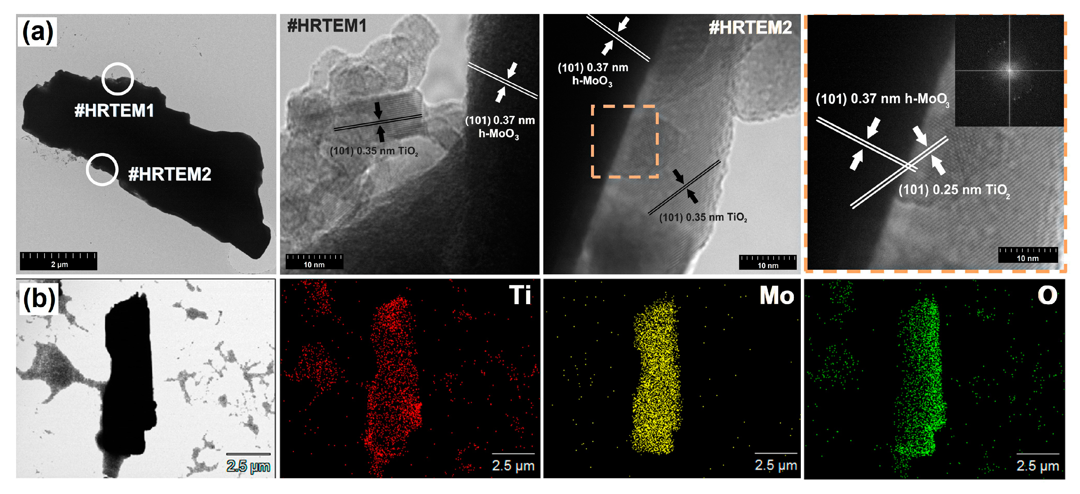
The crystalline structure of materials determines their potential applications in various fields. XRD patterns for all synthesized composite materials are presented in Figure 2a. Sharp, clear diffraction peaks confirm the crystalline nature of all obtained metal oxide samples. For the reference TiO2 sample, the recorded diffraction peaks can be assigned to the anatase crystalline structure (space group I41/amd, no. 141, JCPDS No. 21-1272) and the respective crystalline planes (101), (004), (200), (105) (204), (116) and (220). The MoO3 synthesized in this work crystallizes in a hexagonal structure (space group P63/m, no. 176, JCPDS No. 21-0569). Crystalline planes such as (110), (200), (101), (111), (201), (220), (130), (211), (311), (410), (002), (102), (212), (331), (241), (312), (232) and (412) were observed for the MoO3 sample. In the case of the TiO2-MoO3 composite systems, we observed diffraction peaks characteristic for both anatase and hexagonal molybdenum trioxide (h-MoO3) phases. In all cases, the MoO3-phase peaks were narrower, suggesting a larger size of crystallites. The diffractograms were free of ternary phases, confirming the high quality of the obtained materials. The intensity of the peaks changed gradually as the content of individual phases varied. The weight fraction (% wt.) and the lattice parameters of each phase, given in Table 2, were determined using Rietveld refinement. A sample fitting performed with Fullprof software is presented in Figure 2b for the Ti5Mo5 sample. The resulting weight ratio, when converted to molar, correlates well with the nominal ratio. The refined lattice parameters are in good agreement with those reported in the literature [36,37].
The formation of titania with an anatase structure using the microwave method was reported by Jena et al. [38] and Suprabha et al. [39]. The obtained TiO2 nanoparticles were applied as a photoactive catalyst. However, Suprabha et al. [39] reported the influence of precipitating agents on the physicochemical properties of the final product, including crystallinity and morphology. These results correspond well with the data on the crystallinity of TiO2 obtained in the present study. Current knowledge concerning the synthesis of a hexagonal structure of MoO3 via the microwave method is not yet sufficient. However, Zakharova et al. [40] reported on electrochemical studies of α- and h-MoO3 synthesized via a microwave-assisted hydrothermal method. Therefore, the obtaining of well-formed crystalline forms of anatase and h-MoO3 is an additional novelty of this work.
The crystallite sizes (D) for all samples, together with the lattice strain (ε) calculated using the Williamson-Hall method (Equation (1)), are given in Table 2. In all cases, D values for the h-MoO3 phase are larger than for the TiO2 phase. For the pristine MoO3 sample D is close to 100 nm, while for the TiO2 phase (even for a pure sample) it does not exceed 22 nm, and in other cases it remains around 10 nm. Concurrently, the ε values for the TiO2 phase are on average an order of magnitude higher than for the MoO3 phase.
TiO2-MoO3 systems are well described in the existing literature, for example by Liu et al. [41], Kokorin et al. [42], Sivaranjani et al. [43], Silvestri et al. [44] and Li et al. [26]. However, it should be noted that all of these works concern the synthesis of α-MoO3 and therefore refer to materials other than those described in the present work. To the best of our knowledge, TiO2-MoO3 systems obtained using microwave treatment have not previously been described in the scientific literature. Only one report is currently available regarding the synthesis of a similar system to that described by us. However, Sviridova et al. [45] did not describe the crystalline structure of this material, which was obtained by spraying thin layers of the respective precursors. The use of the microwave method for the synthesis of a composite system made it possible to obtain high-crystalline materials with a specific structure: anatase and h-MoO3.
Raman spectroscopy was performed to confirm the presence of crystalline structures in the obtained materials. The Raman spectra for TiO2-MoO3 systems and reference samples are presented in Figure 3.
The Raman spectrum of the reference TiO2 sample contains five characteristic bands located at 140 cm−1 (Eg-symmetry), 195 cm−1 (Eg), 395 cm−1 (B1g), 520 cm−1 (B1g+A1g) and 640 cm−1 (Eg), assigned to the anatase phase of TiO2 [46]. Furthermore, the Raman spectrum of MoO3 includes five bands characteristic for the metastable h-MoO3 [47,48] phase at 250 cm−1 (B3g), 485 cm−1 (B1g), 685 cm−1 (B3g), 900 cm−1 (B1g) and 970 cm−1 (A1g, B1g). For the analyzed TiO2-MoO3 composite systems, both anatase and h-MoO3 phases were observed. The results of Raman spectroscopy also confirmed the effect of the molar ratio of the reagents on the crystalline structure of the resulting materials. The presented data are consistent with the results of XRD analysis as described above.

3.2. Morphology

To define the morphology and microstructure of the obtained composite materials, scanning and transmission electron microscopy (SEM and TEM) were performed. We first present the results of SEM analysis (Figure 4).
For the reference TiO2 sample (Figure 4a), irregular-shaped particles and high aggregation were observed, as expected. On the other hand, MoO3 particles have a very well defined anisotropic shape in the form of rods with a hexagonal base (Figure 4e). The morphology obtained for both TiO2 [49,50,51] and MoO3 [52,53,54] materials is well described in the scientific literature. The characteristic hexagonal structure of MoO3 and spherical TiO2 particles were found for all of the synthesized TiO2-MoO3 composite systems. Furthermore, it was observed that titanium dioxide particles were deposited on the surface of the hexagonal molybdenum trioxide. This was enabled by the use of the modifier Pluronic P123, which is a popular block copolymer used to obtain mesoporous structures, especially in the soft template method [55,56,57]. However, it is also increasingly used to support pressure methods (hydrothermal or microwave) and to control the morphology of synthesized materials [58,59,60].
There is currently a lack of scientific reports regarding the synthesis of TiO2-MoO3 systems. Among others, Silvestri et al. [44] obtained titania-molybdenum trioxide materials, using a calcination procedure. Such composite systems contained nanometric particles with regular shape. In another work, Sivaranjai et al. [43] described the synthesis of the aforementioned systems as thin films. Hydrothermal-assisted synthesis was used by Li et al. [26] to obtain a nanometric core-shell structure with titania as the core and molybdenum trioxide as the shell. Liu et al. [27] used titania nanobelts for the synthesis of TiO2-MoO3 systems. These materials were obtained using hydrothermal treatment and a calcination process and consisted of micrometric disks with a hexagonal shape (MoO3) and titania nanobelts. It is thus clear that different morphologies were obtained in the aforementioned investigations than those presented in our work.
Since the microwave method was not used in any of the studies listed above, it can be assumed that both the use of a surfactant (Pluronic P123) and microwave irradiation are factors which significantly influence the formation of the described morphological structures.
The results of high-resolution transmission electron microscopy (HRTEM) and EDS analysis for materials synthesized at TiO2:MoO3 molar ratios of 8:2 and 2:8 are presented in Figure 5 and Figure 6. Based on the obtained TEM images (Figure 5a and Figure 6a), it was found that single particles of molybdenum trioxide with a length of approx. 14 µm and a width of 5 µm were present in the systems obtained at molar ratios TiO2:MoO3 = 8:2 and 2:8. The size of the particles observed under the microscope is obviously much larger than the size of crystallites (coherently scattering domains) determined from XRD measurements (Table 2): particles are sets of many grains that may be polycrystalline, single-crystal or amorphous. Similar nanometric average crystallite sizes and micrometric particle sizes for the hexagonal phase of molybdenum trioxide were reported by Chithambararaj et al. [61] and by Lunk et al. [37]. Moreover, rod-like and cubic TiO2 particles were observed in the HRTEM images for the analyzed materials. EDS mapping clearly indicates the deposition of TiO2 on the surface of the MoO3 rods in both cases. Moreover, it should be noted that crystallographic spacing characteristic for the plane (101) of anatase (0.35 nm) and (101) of hexagonal MoO3 (0.37 nm) can be observed in the analyzed materials. The crossing of the crystallographic plane (101) of TiO2 and (101) of MoO3, obtained in the analyzed composite materials, may indicate a surface junction and an associated improvement of the properties of the binary materials compared with the reference samples. Similar observations have previously been reported by Qin et al. [62], who observed a surface junction of titania-based materials synthesized using the sol-gel method. Moreover, Zhand et al. [63] indicated that the surface junction, a special case of heterojunction, may also improve other properties besides the photoactivity of the material. The use of template-assisted microwave synthesis enabled the incorporation of crystalline TiO2 nanoparticles on the surface of the high-crystalline micrometric hexagonal particles and the formation of a stable junction between titania and molybdenum trioxide.

3.3. Parameters of the Porous Structure

Low-temperature nitrogen sorption (the Brunauer-Emmett-Teller method) is one of the most important physicochemical parameters used to describe the new two-component materials. The nitrogen adsorption/desorption isotherms for the obtained materials are presented in Figure 7.
Type IV [64] isotherms were observed for all of the analyzed materials. For titania, an H1 hysteresis loop [64] was observed in the range of (p/p0) from 0.60 to 0.90. In addition, this material had the highest surface area, equal to 119 m2/g. This is similar to the surface areas reported by Drunka et al. [65] and Falk et al. [66], who also used the microwave-assisted method for the synthesis of titania. For the second reference material, MoO3, an H3 hysteresis loop in the range of (p/p0) from 0.51 to 0.91 was observed, and the BET surface area was 2 m2/g. The low surface area of molybdenum trioxide is associated with the high crystallinity (large crystallite size), as indicated using XRD analysis. Similar ABET values have been reported by other researchers, such as Jittiarporn et al. [67] and Yang et al. [68], who obtained hexagonal MoO3 using the hydrothermal method. For the material obtained at the molar ratio TiO2:MoO3 = 8:2, an H1 hysteresis loop [64] was observed similar to that of the TiO2 reference sample; however, the surface area was significantly lower (ABET = 57 m2/g). A similar pattern was noted for the other two composite systems; the BET surface areas were 29 m2/g for the Ti5Mo5 sample and 11 m2/g for Ti2Mo8. In addition, an H1 hysteresis loop [64] was observed for the material obtained at an equimolar ratio of reagents and an H3 hysteresis loop [64] for the system synthesized at a TiO2:MoO3 molar ratio of 2:8. Furthermore, the pore volume and pore diameter were determined for titania (Vp = 0.30 cm3/g, Sp = 8.6 nm) and for MoO3 (Vp = 0.01 cm3/g, Sp = 15.8 nm). Analysis of the parameters determined for TiO2-MoO3 composite systems indicates that a change in molar ratio (decrease of TiO2 content) causes a significant reduction of pore volume at a similar pore diameter (approximately 9.2 nm for all systems). This is due to the fact that the hexagonal MoO3 particles are coated with TiO2 particles, hence the decrease in the TiO2 molar ratio reduces the thickness of the coating, which results in a significant reduction of pore volume.
The results obtained for TiO2-MoO3 composite systems may be compared with data from previous reports. Li et al. [69], who obtained a TiO2-MoO3 system using a self-supporting ammonia method, reported that for a material with a MoO3 content of 61%, a surface area of 37 m2/g and a pore volume of 0.08 cm3/g were obtained. Similar values were reported by Chary et al. [70], who synthesized materials based on titania and molybdenum trioxide using the hydrothermal method with subsequent air calcination. In this case, for materials containing 6% and 12% wt. Mo, the respective ABET values were 57 m2/g and 31 m2/g.

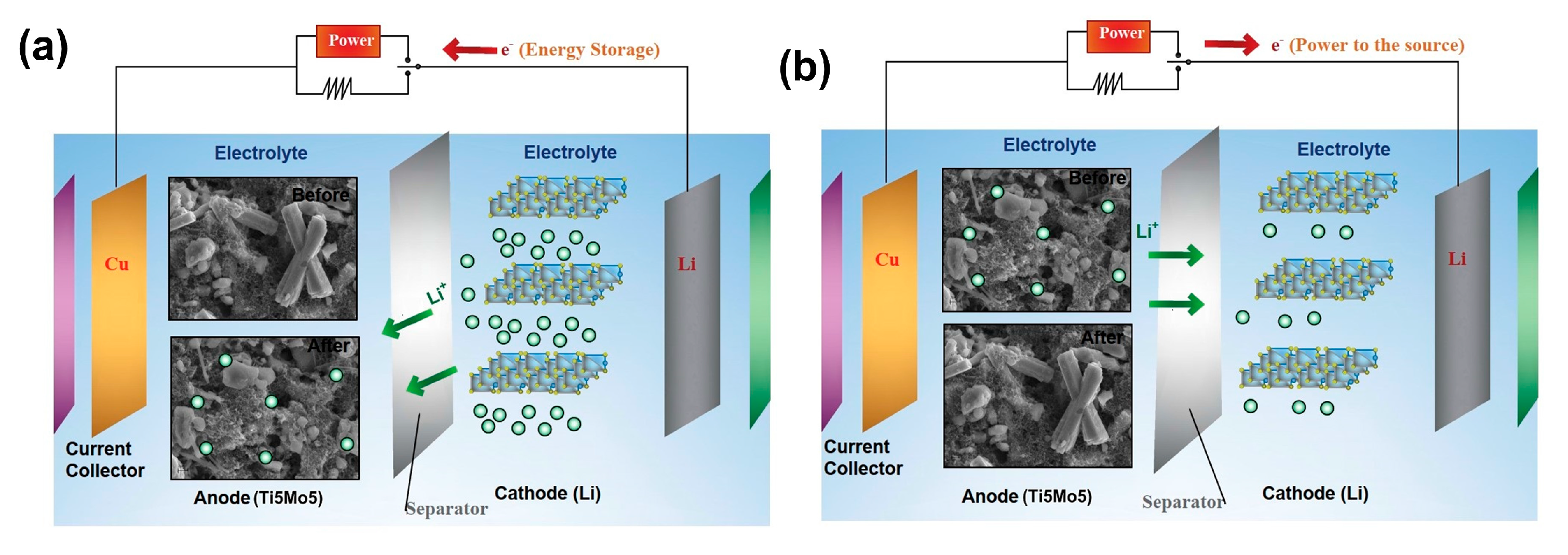
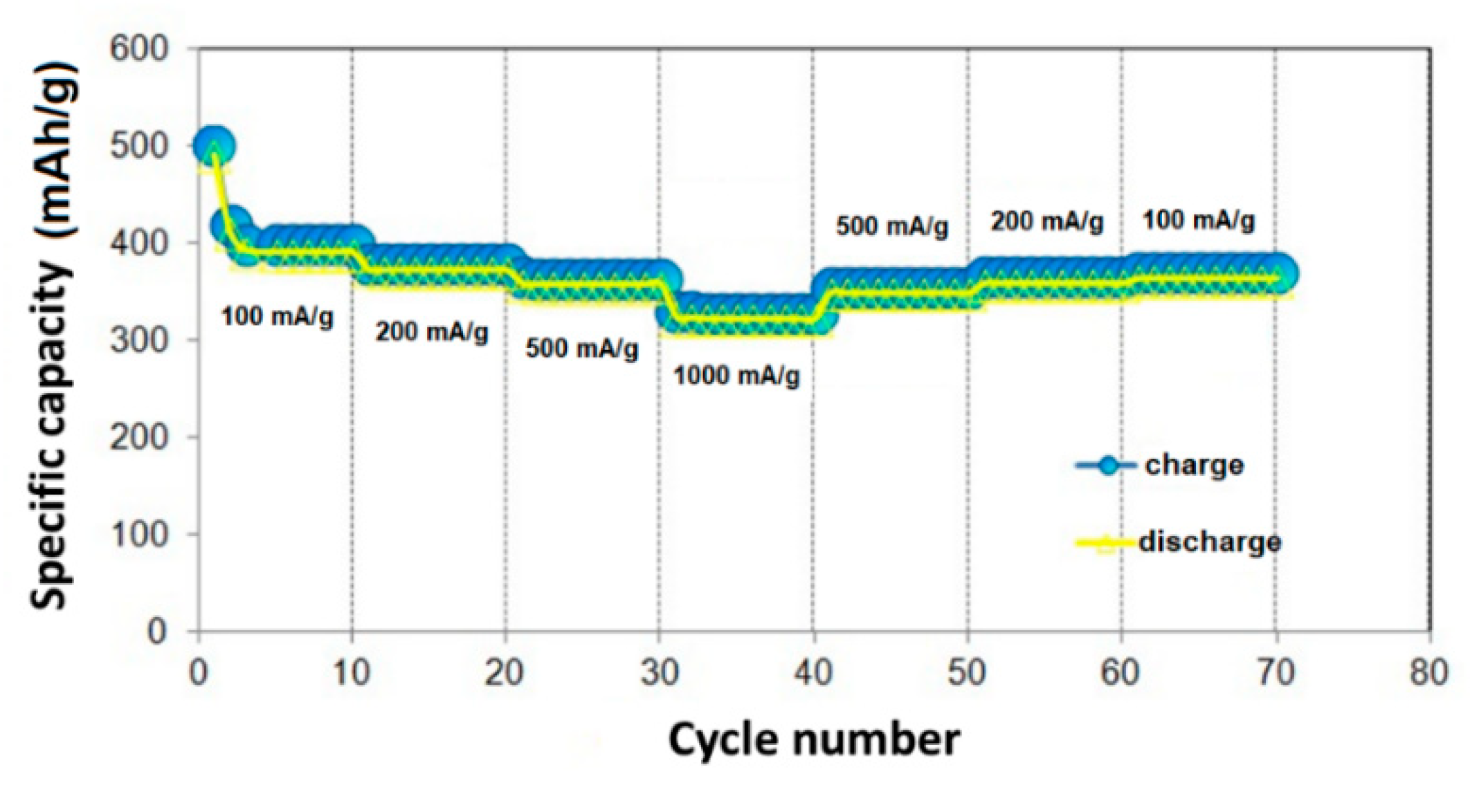
3.4. Charging/Discharging Tests

To determine the electrochemical properties of the materials, charge storage kinetics analysis was carried out. The rate capabilities, discharge capacities and coulombic efficiencies of commercial MoO3 are presented in Figure 8.
The data presented in Figure 8 indicate the rate performance of the electrodes, which is very significant for practical applications in lithium ion-batteries (LIBs). The rate capabilities of MoO3 were measured from 100 to 1000 mA/g (Figure 8a). At a rate of 100 mA/g, the molybdenum trioxide electrode’s discharge capacity decreased at first from a value of 1190 to 900 mAh/g during the first four cycles and then remained constant at ~900 mAh/g during the next five cycles. The average specific capacities of the MoO3 were approx. 900, 820, 800 and 700 mAh/g when the current densities were increased to 0.1, 0.2, 0.6 and 1 A/g respectively. The discharge capacity immediately returned to ~810 mAh/g when the current density was reduced to 0.2 A/g after 60 cycles, and the slight capacity changes suggest good resilience of the MoO3 electrode material at high current densities. Current densities had a significant impact on the discharge capacities, as presented in Figure 8b. Coulombic efficiency at a current density of 500 mA/g after 100 cycles was approx. 95%, while at 100 mA/g it rose to 98%. After approx. 10 cycles, the stability was very good in both cases. For a current density of 100 mA/g, even an increase in capacity and lifetime from 72% to 90% was observed after approx. 30 cycles. For a current density of 500 mA/g, after the same number of cycles, the capacity decreased from 70% to 62%. Thus, the cell works better at lower current densities, maintaining favorable capacities during discharge after up to 70 cycles [23].
Among numerous devices and systems used for energy storage, Li-ion batteries deserve particular attention due to their promising performance parameters, which include high energy density, high operating voltage, low self-discharge rate, good cyclic durability and a wide range of operating temperatures. Currently, one of the greatest challenges in the construction of lithium-ion systems is to find new material solutions that will result in reduced costs, improved operating parameters and cell safety.
In the literature we can read that Li-ion battery anodes fabricated from crystalline MoO3 nanoparticles display an anomalous reversible capacity of 630 mAh/g when cycled at high rates. The nanoparticle anodes show no degradation of capacity for 150 cycles, whereas micron-sized MoO3 particles are shown to fail after several cycles. Theoretical calculations elucidate the Li-ion intercalation mechanism and explain the reversible capacity.
Loss of capacity is a common phenomenon for modified MoO3. With the Ti2Mo8 hybrid, the system had already lost 60% of its capacity after 30 cycles, therefore it was not subjected to more detailed electrochemical analysis. As is well known, pure TiO2 does not exhibit good electrochemical properties, which was confirmed by the tests for Ti8Mo2, where a significant charge transfer resistance prevented the charging/discharging process.
In the next step, the rate performance was investigated for the selected TiO2-MoO3 system (sample Ti5Mo5).
Changes in the rate capability of the TiO2-MoO3 electrode (sample Ti5Mo5) as the current density was gradually decreased in a stepwise manner from 100 to 1000 mA/g and finally returned to 100 mA/g are presented in Figure 9.
At a current density of 100 mA/g, the Ti5Mo5 electrode delivered the highest reversible capacity, with unstable values in a range from 400 up to 500 mAh/g. After that point, the current density was relatively stable. Decreasing capacity was recorded during the first three cycles; subsequently, the values were quite stable. Even after 70 cycles, a value of 400 mAh/g was maintained. At higher current densities of 200 mA/g and 500 mA/g, the electrode still exhibited a stable, reversible capacity of 380 mAh/g and 370 mAh/g respectively. When cycled at 1000 mA/g, the average reversible capacity was approx. 330 mAh/g, which is not as high as the theoretical capacity of graphite (372 mAh/g) but still satisfactory. It is due to the presence of the electrochemically undesirable TiO2 that the capacities decrease after charging/discharging in comparison with molybdenum trioxide. According to literature reports [12,23,71], titania-based anode materials are characterized by low inherent theoretical capacity (175 to 330 mAh/g), which confirms much lower capacities. At 30–40 cycles a slightly unstable capacity could be observed. This comparison indicates that carbonaceous materials behave similarly to titanium oxide systems. Notably, when the current density was returned to 100 mA/g, the reversible capacity quickly reached its primary value of 400 mAh/g, suggesting that the Ti5Mo5 electrode could remain stable after many cycles at high current density. This also confirms the long cycle life characteristic for titanium dioxide materials. As can be observed, a TiO2:MoO3 ratio of 5:5 enables good specific capacity for almost all current densities due to the presence of molybdenum trioxide and excellent intercalation of lithium ions due to the presence of titanium dioxide, which results in an electrochemically favorable and safe system. It should be noted that a higher current regime always leads to some capacity problems, but this issue is not particularly visible in the case of the studied systems. The maximum current density at which the capacitance was measured was 1000 mA/g. When the current density changed, the stability of the system was extremely high for every 10 cycles. The MoO3 sample has twice as high specific capacity at almost the same current density after the same number of cycles compared with the TiO2-MoO3 system (sample Ti5Mo5). Capacitive stability at every current density was similar, as in case of the above-mentioned material. Su et al. [72] studied another system using TiO2, namely TiO2/WO3-W (prepared by the laser ablation method), used as a coater, and did not obtain such a stable variation of the specific capacities at higher current densities. For a current density of 1000 mA/g, a capacity of 200 mAh/g was obtained (compared to 300 mAh/g in this study), which confirms that the use of MoO3 as a transition metal oxide and electrochemically active material at high current densities is reasonable.
MoO2 oxide (nano) has a high capacity of 838 mAh/g based on the conversion reaction [73,74]. Unfortunately, it has the disadvantage of changing the volume of MoO2 during the introduction of lithium ions. Additionally, extraction leads to powdering of particles and discontinuities in transport paths of electrons and ions, which results in a serious loss of capacity [75]. In addition, MoO2 nanoparticles tend to aggregate, increasing mass, which extends ion diffusion pathways and reduces electrochemical active sites, leading to reduced performance [76]. To address these drawbacks, the dispersion of MoO2 nanoparticles into two-dimensional (2D) materials has been proposed. It has been demonstrated that 2D materials, due to the matrix, can prevent aggregation of MoO2 nanoparticles during cycles. It is known that MoS2 as a 2D material has high theoretical capacity (~670 mAh/g) and good capacity, thus it is expected that good electrochemical performance will be obtained with MoO2/MoS2 composite. MoO2/MoS2 composites show increased cyclic stability and storage of lithium ions [77]. Therefore, research on the production of various composites, including MoO2/carbon (MoO2/carbon nanotubes [78], hybrid MoO2/carbon nanowires [79] and MoO2/graphene [80]) is another effective route to improve electrochemical efficiency.
MoOx materials are still undergoing many modifications. There are many approaches described in the literature, and the effects are varied. Generally, one cannot assume that a poorer capacity signifies a poorer anode material. As mentioned earlier, there are many factors involved. The Table 3 gives some examples for comparison.
To analyze the electrochemical performance of the TiO2-MoO3 system, a galvanostatic charge/discharge test was performed. The curves for electrodes containing the aforementioned selected composite system (sample Ti5Mo5) during the initial three cycles at 50 mA/g are presented in Figure 10.
The charging/discharging curves, which show the three-step process of intercalation and deintercalation of lithium ions, are presented in Figure 10. It should be taken into account that, initially, the discharge and charge curves do not show a stable potential dependence on capacity. After the first cycle, the discharging/charging capacity was 1227 mAh/g, and after the 100th cycle, it was 744 mAh/g. The potential decreases when the cell is discharged, which is not a positive phenomenon in terms of stability and performance. In addition, the capacity of the cell decreases by approx. 500 mAh/g after 100 charging cycles. The shape of the curves is very similar to those described by Subba Reddy et al. [86]; however, in that study MoO3 was used as the cathode. The total reversible capacity was equal to 750 mAh/g after 100 cycles, which indicates that its capacity is twice as high when used an anode as when used as a cathodic material. It should be noted that in this study the system includes titanium oxide, which increases the intercalation of lithium ions, hence its use increases the stability as well as the capacity of the cell. Significant changes in the reversible capacity after 1–100 cycles were only visible at a voltage lower than 1.5 V. Moreover, the curves indicate lower system stability during charging and discharging. There was no clearly defined plateau.

3.5. Cyclic Voltammetry and Impedance Spectroscopy Tests

The materials used as the electrode in lithium-ion batteries usually exhibit electrochemical activity to react with lithium ions. To distinguish the electrochemical activity of the oxide materials, cyclic voltammetry (CV) analysis was used. The CV curves for reference samples are shown in Figure 11.
Titania exhibited a cathodic peak at a potential of 1.5 V (intercalation/deintercalation of Li+) and an anodic peak at 2.3 V. Molybdenum trioxide presents good cyclic stability after the second and third cycles. During the first cycle, reversal of the reaction from oxidation to reduction and vice versa occurs at a lower potential of 2.5 V, and not 3 V as in other cases. At this potential, an irreversible electrode reaction could be observed. Slight reduction of peaks is visible at 1 V, 1.4–1.5 V and 1.75–2.1 V. Oxidizing peaks are well exposed at voltages of 1 V and 1.8 V.
In the next stage of CV tests, the selected TiO2-MoO3 system (sample Ti5Mo5) was analyzed (Figure 12).
The peaks for MoO3 are not visible in Figure 12 because the electrode was able to swell, which remains a major problem with the use of titanium dioxide as part of an anode material. As can be seen in Figure 12a, at the first cycle a reduction peak was observed at a potential of 1.4 V and an oxidizing peak at a voltage of 2.0 V. The oxidizing peak in the second cycle shifts to 2.5 V. Thus, at 2.0 V an irreversible charging occurred. The cathodic peak in the voltage range 1.5–2.0 V is due to Li+ intercalation into the titanium dioxide surface. According to Lim et al. [87], two phases may be present in the studied system: the first with a low amount of Li+ and the second rich in Li+. The Li-poor phase is tetragonal Li0.01TiO2, and the second is orthorhombic Li0.55TiO2. The results obtained suggest good cyclic stability of the system, because only the first cycle was a stabilizing cycle, while cycles 2 and 3 were identical (Figure 12b), which corresponds to high cyclic stability. Cycle 4 was not included in this work, because it was identical to cycles 2–3. The disappearance of molybdenum trioxide peaks is also associated with the hundred times greater BET surface area of titanium dioxide. At the same time, molybdenum trioxide is a very good sorbent, hence its surface does not have to be very large, although titanium dioxide will be responsible for the reduction and oxidation peaks. This is caused by the fact that titanium dioxide pores are almost two times smaller than those of MoO3, which increases the adsorption capacity and leads to a greater intercalation of lithium ions. Lim et al. [87] obtained similar cyclic voltammetry results to those presented in Figure 12, using a TiO2-C system. This comparison is used here because 30% of the anode material consisted of carbon materials, which can also have a notable impact on the occurrence of, for example, higher and thinner oxidizing peaks. The use of carbon further increases the intercalation and adsorption ability of the surface, because of the large surface area and small pores. The presence of anodic/cathodic peaks confirms that TiO2-MoO3 may be practically used in LIBs as an anode material.
The proposed intercalation/deintercalation mechanism during charging and discharging should take account of the presence of both TiO2 and MoO3 as well as the carbonaceous material which is a part of the electrode material. TiO2 is mostly responsible for the intercalation/deintercalation process and, according to Figure 14, the main mechanism is de/-intercalation, as expressed by Equation (2).
( )   T i O 2 + L i + + e L i T i O 2
H e n c e ,   ( )   T i 3 + + e T i 2 +
Equation (2) represents the mechanism associated with the disordered and ordered TiO2 surface proposed by J. Lu et al. [23] and X. Lu et al. [71]. In this study, we propose mechanisms of transition to Ti2+, as presented in Equations (4) and (5).
( )   L i T i O 2 + L i + + e L i 2 T i O 2
H e n c e ,   ( )   T i 3 + + e T i 2 +
The mechanism of reduction of Ti4+ to Ti2+ can proceed straight to oxidation state +2, omitting +3, as has been described in the literature [29].
According to Figure 1, conversion is expected to be the main mechanism during the charging/discharging process of molybdenum oxides, but it was not confirmed whether the oxide transforms to lower oxidation states of molybdenum than +4. If the molybdenum ion (+6) does not transform to +2 to form MoO because of the presence of TiO2, the conversion process is not confirmed, which is in agreement with the obtained CV diagrams (Figure 12), in which molybdenum peaks were not observed. If the conversion is possible, the mechanism in this study would be based on Equations (6)–(9), which are found in the literature [23,72,88].
V > 1.5 V   M o O 3 + x L i + + x e L i x M o O 3   ( x 0 2 )
L i x M o O 3 + ( 6 x ) L i + + ( 6 x ) e M o + 3 L i 2 O
M o + 2 L i 2 O M o O 2 + 4 e + 4 L i +
M o O 2 + L i 2 O M o O 3 + 2 e + 2 L i +
At the same time, because of the presence of carbon in the form of graphite (GR) and acetylene black (AB) as part of the anode material, the reaction given by Equation (10) may occur, as proposed by Li et al. [23].
( ) L i x C C + x L i + + x e
The Nyquist charts consist of two parts: a semi-circle in the high–mid frequency region and a linear curve in the low frequency region. Impedance values were measured after preparation of the electrode and after cell charging and discharging (Figure 13). The presence of a semicircle indicates the resistances associated with the exchange of charges between materials and electrolyte and the formation of the SEI (solid electrolyte interface) layer, and the more SEI layers that are formed, the longer the cell life—as well as the higher the cyclic stability and safety—that can be obtained. Resistance due to the electrolyte Rel is not visible because it was negligibly small (≈0–2 Ω). Resistance associated with the transfer of charges Rct was equal to 205 Ω and 150 Ω before and after the process respectively. The SEI (RSEI) layer was formed in a range from 2 to 205 Ω and from 2 to 150 Ω before and after the process respectively. After the reversible process, the impedances due to linear parts are much smaller, which is due to the accumulation of Li+ ions through diffusion as this transport mechanism is intensified. Additionally, the diameter of the semicircle is much smaller, which is due to overcoming the resistance of exchange of charges due to electrode reactions after charge/discharge and a smaller SEI layer, because providing energy makes it possible to overcome the resistance and increase the conductivity. The occurrence of inclined linear curves at an angle of approx. 45 degrees indicates the occurrence of the so-called Warbung element, offering infinite diffusion to a flat electrode, occurring regardless of frequency. Similar curves were obtained by Zhou et al. [76] for MoO2 carbon fibers, which confirms the reduction process of Mo+6 to Mo+4 at the Li metallic cathode in this case. The SEI layer is unstable and is degraded after the process of charging/discharging, which is very common and confirmed for molybdenum oxides [23].
During charging, Li+ is removed from the cathode and transferred to the anode (intercalation), and electrical energy (because of the presence of an electrical circuit) is applied, hence the conversion of electrical energy to chemical energy is observed. TiO2 enables the intercalation of lithium ions. Both mechanisms—conversion and intercalation—are observed here (Figure 14). SEM images show intercalated lithium ions and their incorporation into the structure of molybdenum trioxide.

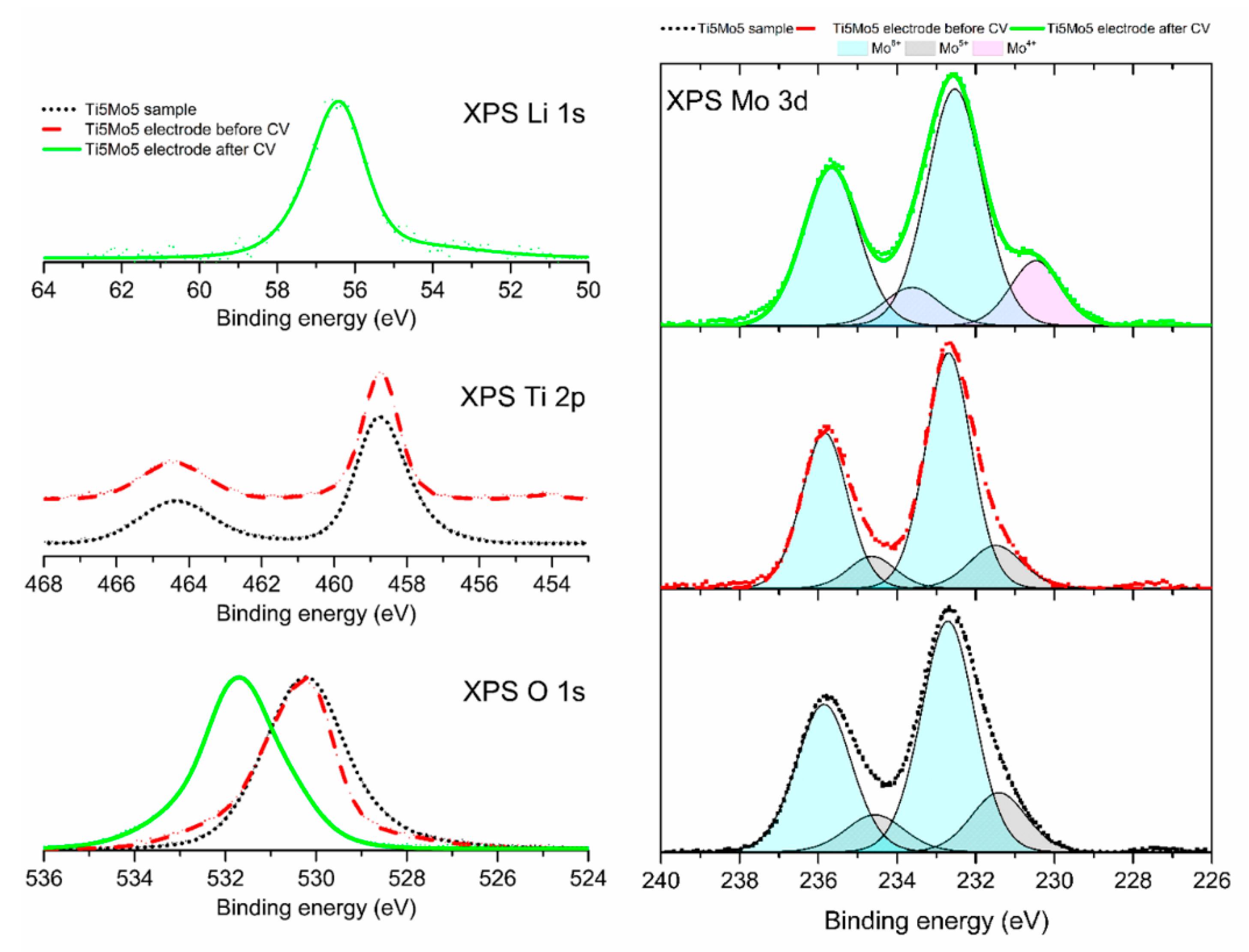
3.6. Surface Composition

X-ray photoelectron spectroscopy was applied to investigate the surface compositions of the Ti5Mo5 composite sample after its preparation, as well as Ti5Mo5 electrodes before and after cyclic voltammetry experiments. The estimated surface atomic concentrations of elements identified on the surface of these samples are shown in Table 4.
The determined surface composition of the material Ti5Mo5 corresponds well with the previous data on the phase composition of that material. The atomic percentage ratio Ti:Mo was found to be 12:13, which is very close to the molar ratio of 1:1 confirmed using XRD analysis. Based on the stoichiometric composition of the system consisting of TiO2 and MoO3, the atomic percentage of oxygen atoms on the surface should be 63%, while the observed concentration of oxygen atoms was 62%. The surface of this material was marginally contaminated by adventitious carbon.
During the slurry tape casting procedure used to form the Ti5Mo5 electrode, 70% wt. TiO2-MoO3 oxide systems were mixed with 15% wt. of acetylene black and 15% wt. of poly(vinylidene fluoride) (PVdF) dissolved in N-methyl-2-pyrrolidinone (NMP). The resulting surface composition of the electrode was very different from that calculated with the assumption of a homogeneous blend of substrates. The inorganic parts of the electrode, TiO2 and MoO3 oxides, are barely exposed to the surface. Their atomic concentrations were equal, but amounted to only 2%. The majority of the surface consisted of carbon and PVdF, which screen the transition metal ions.
After the CV experiments, the elemental surface composition of the Ti5Mo5 electrode again changed considerably. Since the electrode was exposed to the electrolyte, the presence of phosphorus and lithium (from LiPF6) was expected. The presence of small amounts of copper results from the copper foil used as a contact. Surprisingly, titanium was not observed on the surface of the used Ti5Mo5 electrode. Since other analytical methods used to evaluate the composition of this material did not indicate the total removal of titanium compounds, it is reasonable to assume that the titanium compounds are screened by other components of the system. Therefore, titanium atoms could not be detected, since the information depth of Ti 2p photoelectrons emitted from that material does not exceed a value of approximately 10 nm. However, the presence of molybdenum atoms in the absence of titanium atoms implies the detachment of MoO3 and TiO2 particles during the electrochemical experiments. The surface concentration of lithium was very high (31% at.), almost equal to the concentration of oxygen atoms (32% at.). The surface of the analyzed sample was also less abundant in carbon than before the CV experiments.
High-resolution X-ray photoelectron spectra (Figure 15) were acquired to analyze the chemical composition of the surface of that material and its evolution during the preparation stage and CV experiments. The XPS Ti 2p signal was observed as a spin-orbit coupling doublet. In the case of the Ti5Mo5 composite sample, the Ti 2p3/2 component of that transition was located at a binding energy of 458.8 eV, with the Ti 2p3/2 to Ti 2p1/2 shift equal to 5.5 eV. These values are characteristic for pure TiO2 [89]. After preparation of the Ti5Mo5 electrode, the position of Ti 2p peaks was unchanged, which indicates that there is no chemical transformation of titanium compounds during the preparation stage. As mentioned before, the XPS Ti 2p signal was not detected for the sample exposed to the CV experiments, therefore, it was not possible to evaluate the evolution of TiO2 during the electrochemical process.
The XPS Mo 3d signal (Figure 15) was observed for the Ti5Mo5 system at a binding energy of 232.7 eV (the position of the Mo 3d5/2 component). The shift between Mo 3d5/2 and Mo 3d3/2 peaks was equal to 3.15 eV. Similarly to the evaluation of titanium, the XPS peaks for molybdenum confirmed the presence of MoO3 [90]. However, a slight asymmetry at the low energy side of the Mo 3d5/2 component was noted. Therefore, a deconvolution of the Mo 3d spectrum envelope was performed. The observed asymmetry can be well corrected assuming the presence of a second spin-orbit doublet shifted towards the low energy region. The maximum of the Mo 3d5/2 component of that doublet is located at 231.4 eV. This value is attributed to the presence of Mo5+ ions. They constitute approx. 20% of the total Mo 3d signal observed for that sample. It is assumed that the hydrothermal procedure used to prepare the materials results in a partial disordering of the oxygen sub-net of MoO3, inducing the formation of Mo5+ ions.
There was no significant change in the Mo 3d signal on the surface of the Ti5Mo5 electrode in comparison to that observed in the Ti5Mo5 system. The second Mo 3d doublet corresponding to Mo5+ ions constituted approx. 17% of the total Mo 3d signal, which is considered to be within experimental error.
A significant change was observed for the Mo 3d line after the CV experiment. The principal maximum of the Mo 3d5/2 component was not shifted; however, a new feature of the envelope was observed at a binding energy of approx. 230 eV. The deconvolution procedure revealed a new spin-orbit doublet formed in the Mo 3d spectrum. Its maximum was located at 230.4 eV, and its intensity reached approx. 20% of the total Mo 3d signal. The location of the maximum at approx. 230 eV can be attributed to the formation of Mo4+ ions in the material [90,91]. The existence of a similar Mo 3d peak was attributed to the formation of Li2MoO3 compound during the preparation of thin film electrodes [92]. Therefore, a partial reduction of the Mo6+ ions present in MoO3 to Mo4+ ions is suggested.
The photoelectron spectra of oxygen and lithium correlate well with the data for titanium and molybdenum. Considering the pristine Ti5Mo5 material, only oxygen atoms from TiO2 and MoO3 should contribute to the XPS O 1s signal. Indeed, a distinct line with a maximum located at 530.2 eV was observed. This binding energy value is characteristic for bulk atoms of both TiO2 and MoO3 [91,92,93,94]. There is no change in the position of the O 1s peak after preparation of the Ti5Mo5 electrode. However, a significant shift of the XPS O 1s line was observed for that sample after the CV experiments. The maximum of the O 1s line is located at a binding energy of 531.8 eV. This binding energy region can be attributed to different oxygen-bearing compounds. Since the XPS Mo 3d signal is weak, the electrons originating from Mo-O compounds are not considered to be the main contributors to that peak. The electrolyte contains some organic compounds as carbonates. C=O or COOR type bonds are the origin of XPS O 1s components in the binding energy region of approx. 531.5 eV [92,95]. Therefore, they cannot be disregarded. This region might also represent a surface component of transition metal oxides or Me-OH bonds. However, comparison of the atomic concentrations of molybdenum atoms (3%) and oxygen atoms (32%) rules out that explanation. The XPS Li 1s spectrum acquired for the sample after the CV experiment indicated that the maximum of the Li 1s line is located at a binding energy of 56.4 eV. The position of the XPS Li 1s line at approx. 56 eV generally corresponds with Li+ ions [95,96]. The position of the XPS O 1s line observed for Li2O was at 531.2 eV, similar to that observed for the Ti5Mo5 electrode. It should also be considered that the concentrations of oxygen and lithium atoms are both very high. Therefore, it is supposed that Li+ ions can form Li-O bonds.

4. Conclusions

One of the goals of this work was to use the template-assisted microwave method for synthesis of highly crystalline TiO2-MoO3 materials. Moreover, the use of this novel synthesis method enabled the incorporation of titania nanocrystalline particles on the hexagonal MoO3 structure. The covering of the hexagonal MoO3 structured surface with titania nanocrystalline particles depends on the TiO2:MoO3 molar ratio. Additionally, the molar ratio influences the physicochemical parameters, such as the crystalline structure (crystallite size and phase composition) and the BET surface area, which varies within the range 11–57 m2/g. Furthermore, it should be emphasized that the synthesized TiO2-MoO3 composite systems included only two crystalline phases: anatase and hexagonal molybdenum trioxide.
In terms of electrochemical applications, it should emphasized that the monoxides such as titanium dioxide impact the safety of the cell, whereas molybdenum trioxide exhibits high capacity and low cost, but its SEI layer is unstable and irregular cyclic voltammetry cycles were observed—values of RSEI lay in a range from 2 up to 205 Ω and from 2 up to 150 Ω before and after the process. Moreover, the resistance associated with the transfer of charges, Rct, was equal to 205 Ω and 150 Ω before and after the process. Additionally, after the 100th cycle the discharge capacity was equal to 744 mAh/g, which significantly exceeds the values for pure TiO2. The use of the TiO2-MoO3 materials significantly facilitates the cathode selection process, increases the battery life and stability at various current densities and many cycles, and offers a promising electrochemical innovation for lithium-ion cells.

Author Contributions

A.K., main contributor, research planning, synthesis of materials, writing draft manuscript; W.W., review of available scientific literature, writing draft manuscript; M.P. and B.K., determining electrochemical properties, writing electrochemical parts; K.S., interpretation of XRD data; E.G., performed TEM/HRTEM and EDS analysis; D.M., responsible for XPS analysis and results interpretation; M.S., responsible for Raman spectroscopy analysis and results interpretation; K.S.-C., responsible for BET analysis; K.S.-C. and T.J., performed critical revision and supervised all aspects of the research. All authors have read and agreed to the published version of the manuscript.

Funding

This work was supported by the National Science Centre Poland under research project no. 2018/29/B/ST8/01122.

Conflicts of Interest

The authors declare no conflict of interest.

References

  1. Gratz, E.; Sa, Q.; Apelian, D.; Wang, Y. A closed loop process for recycling spent lithium ion batteries. J. Power Sources 2014, 262, 255–262. [Google Scholar] [CrossRef]
  2. Scrosati, B.; Abraham, K.M.; Van Schalkwijk, A.; Hassoun, J. Lithium batteries: From early stages to the future. In Lithium Batteries: Advanced Technologies and Applications; Wiley: Hoboken, NJ, USA, 2013; pp. 21–38. [Google Scholar]
  3. Vincent, C.A. Lithium batteries: A 50-year perspective, 1959–2009. Solid State Ion. 2000, 134, 159–167. [Google Scholar] [CrossRef]
  4. Tan, G.; Wu, F.; Zhan, C.; Wang, J.; Mu, D.; Lu, J.; Amine, K. Solid-State Li-Ion Batteries Using Fast, Stable, Glassy Nanocomposite Electrolytes for Good Safety and Long Cycle-Life. Nano Lett. 2016, 16, 1960–1968. [Google Scholar] [CrossRef]
  5. Nitta, N.; Wu, F.; Lee, J.T.; Yushin, G. Li-ion battery materials: Present and future. Mater. Today 2015, 18, 252–264. [Google Scholar] [CrossRef]
  6. Favre, C.; Bosteels, D.; May, J. Exhaust Emissions from European Market-Available Passenger Cars Evaluated on Various Drive Cycles. SAE Tech. Pap. Ser. 2013. [Google Scholar] [CrossRef] [Green Version]
  7. Chen, X.; Shen, W.; Vo, T.T.; Cao, Z.; Kapoor, A. An overview of lithium-ion batteries for electric vehicles. In Proceedings of the 10th International Power & Energy Conference (IPEC); Institute of Electrical and Electronics Engineers (IEEE): Piscataway, NJ, USA, 2012; pp. 230–235. [Google Scholar]
  8. Doughty, D.H.; Roth, E.P. A General Discussion of Li Ion Battery Safety. Electrochem. Soc. Interface 2012, 21, 37–44. [Google Scholar] [CrossRef] [Green Version]
  9. Goodenough, J.B. Changing Outlook for Rechargeable Batteries. ACS Catal. 2017, 7, 1132–1135. [Google Scholar] [CrossRef] [Green Version]
  10. Hu, Y.-Y.; Liu, Z.; Nam, K.-W.; Borkiewicz, O.J.; Cheng, J.; Hua, X.; Dunstan, M.T.; Yu, X.; Wiaderek, K.M.; Du, L.-S.; et al. Origin of additional capacities in metal oxide lithium-ion battery electrodes. Nat. Mater. 2013, 12, 1130–1136. [Google Scholar] [CrossRef]
  11. Xu, K. Electrolytes and Interphases in Li-Ion Batteries and Beyond. Chem. Rev. 2014, 114, 11503–11618. [Google Scholar] [CrossRef]
  12. Siwińska-Stefańska, K.; Kurc, B. Preparation and application of a titanium dioxide/graphene oxide anode material for lithium–ion batteries. J. Power Sources 2015, 299, 286–292. [Google Scholar] [CrossRef]
  13. Sun, Y.; Zhao, L.; Pan, H.; Lu, X.; Gu, L.; Hu, Y.-S.; Li, H.; Armand, M.; Ikuhara, Y.; Chen, L.; et al. Direct atomic-scale confirmation of three-phase storage mechanism in Li4Ti5O12 anodes for room-temperature sodium-ion batteries. Nat. Commun. 2013, 4, 1870. [Google Scholar] [CrossRef] [PubMed] [Green Version]
  14. McEvoy, T.M.; Stevenson, K.J.; Hupp, J.T.; Dang, X. Electrochemical Preparation of Molybdenum Trioxide Thin Films: Effect of Sintering on Electrochromic and Electroinsertion Properties. Langmuir 2003, 19, 4316–4326. [Google Scholar] [CrossRef]
  15. Li, X.; Xu, J.; Mei, L.; Zhang, Z.; Cui, C.; Liu, H.-K.; Ma, J.; Dou, S. Electrospinning of crystalline MoO3@C nanofibers for high-rate lithium storage. J. Mater. Chem. A 2015, 3, 3257–3260. [Google Scholar] [CrossRef]
  16. Chen, J.S.; Cheah, Y.L.; Madhavi, S.; Lou, X.W. (David) Fast Synthesis of α-MoO3 Nanorods with Controlled Aspect Ratios and Their Enhanced Lithium Storage Capabilities. J. Phys. Chem. C 2010, 114, 8675–8678. [Google Scholar] [CrossRef]
  17. Zheng, L.; Xu, Y.; Jin, D.; Xie, Y. Novel Metastable Hexagonal MoO3 Nanobelts: Synthesis, Photochromic, and Electrochromic Properties. Chem. Mater. 2009, 21, 5681–5690. [Google Scholar] [CrossRef]
  18. Hu, Y.-S.; Kienle, L.; Guo, Y.; Maier, J. High Lithium Electroactivity of Nanometer-Sized Rutile TiO2. Adv. Mater. 2006, 18, 1421–1426. [Google Scholar] [CrossRef]
  19. Lin, Y.-M.; Abel, P.R.; Flaherty, D.W.; Wu, J.; Stevenson, K.J.; Heller, A.; Mullins, C.B. Morphology Dependence of the Lithium Storage Capability and Rate Performance of Amorphous TiO2 Electrodes. J. Phys. Chem. C 2010, 115, 2585–2591. [Google Scholar] [CrossRef]
  20. Wagemaker, M.; Kentgens, A.P.M.; Mulder, F.M. Equilibrium lithium transport between nanocrystalline phases in intercalated TiO2 anatase. Nature 2002, 418, 397–399. [Google Scholar] [CrossRef]
  21. Wagemaker, M.; Simon, D.R.; Kelder, E.M.; Schoonman, J.; Ringpfeil, C.; Haake, U.; Lützenkirchen-Hecht, D.; Frahm, R.; Mulder, F.M. A Kinetic Two-Phase and Equilibrium Solid Solution in Spinel Li4+xTi5O12. Adv. Mater. 2006, 18, 3169–3173. [Google Scholar] [CrossRef]
  22. Dahl, M.; Liu, Y.; Yin, Y. Composite Titanium Dioxide Nanomaterials. Chem. Rev. 2014, 114, 9853–9889. [Google Scholar] [CrossRef]
  23. Lu, J.; Chen, Z.; Pan, F.; Cui, Y.; Amine, K. High-Performance Anode Materials for Rechargeable Lithium-Ion Batteries. Electrochem. Energy Rev. 2018, 1, 35–53. [Google Scholar] [CrossRef]
  24. Wang, C.; Wu, L.; Wang, H.; Zuo, W.; Li, Y.; Liu, J. Fabrication and Shell Optimization of Synergistic TiO2-MoO3 Core-Shell Nanowire Array Anode for High Energy and Power Density Lithium-Ion Batteries. Adv. Funct. Mater. 2015, 25, 3524–3533. [Google Scholar] [CrossRef]
  25. Xie, S.; Yao, T.; Wang, J.; Alsulami, H.; Kutbi, M.A.; Wang, H. Coaxially Integrating TiO2/MoO3 into Carbon Nanofibers via Electrospinning towards Enhanced Lithium Ion Storage Performance. ChemistrySelect 2020, 5, 3225–3233. [Google Scholar] [CrossRef]
  26. Li, N.; Li, Y.; Li, W.; Ji, S.; Jin, P. One-Step Hydrothermal Synthesis of TiO2@MoO3 Core–Shell Nanomaterial: Microstructure, Growth Mechanism, and Improved Photochromic Property. J. Phys. Chem. C 2016, 120, 3341–3349. [Google Scholar] [CrossRef]
  27. Liu, H.; Lv, T.; Zhu, C.; Zhu, Z. Direct bandgap narrowing of TiO2/MoO3 heterostructure composites for enhanced solar-driven photocatalytic activity. Sol. Energy Mater. Sol. Cells 2016, 153, 1–8. [Google Scholar] [CrossRef] [Green Version]
  28. Liu, K.; Huang, X.; Pidko, E.; Hensen, E.J. MoO3–TiO2 synergy in oxidative dehydrogenation of lactic acid to pyruvic acid. Green Chem. 2017, 19, 3014–3022. [Google Scholar] [CrossRef] [Green Version]
  29. Gupta, D.; Jamwal, D.; Rana, D.; Katoch, A. Microwave synthesized nanocomposites for enhancing oral bioavailability of drugs. In Applications of Nanocomposite Materials in Drug Delivery; Woodhead Publishing: Cambridge, UK, 2018; pp. 619–632. [Google Scholar]
  30. Roberts, B.A.; Strauss, C.R. Toward Rapid, “Green”, Predictable Microwave-Assisted Synthesis. Chem. Inf. 2005, 36, 653–661. [Google Scholar] [CrossRef]
  31. Priecel, P.; Lopez-Sanchez, J.A. Advantages and Limitations of Microwave Reactors: From Chemical Synthesis to the Catalytic Valorization of Biobased Chemicals. ACS Sustain. Chem. Eng. 2018, 7, 3–21. [Google Scholar] [CrossRef] [Green Version]
  32. Kappe, C.O.; Dallinger, D. The impact of microwave synthesis on drug discovery. Nat. Rev. Drug Discov. 2005, 5, 51–63. [Google Scholar] [CrossRef]
  33. Tompsett, G.A.; Conner, W.C.; Yngvesson, K.S. Microwave Synthesis of Nanoporous Materials. Chem. Phys. Chem. 2006, 7, 296–319. [Google Scholar] [CrossRef]
  34. Rodríguez-Carvajal, J. Recent advances in magnetic structure determination by neutron powder diffraction. Physica B 1993, 192, 55–69. [Google Scholar] [CrossRef]
  35. Williamson, G.; Hall, W. X-ray line broadening from filed aluminium and wolfram. Acta Met. 1953, 1, 22–31. [Google Scholar] [CrossRef]
  36. Ahmad, M.I.; Bhattacharya, S. Size effect on the lattice parameters of nanocrystalline anatase. Appl. Phys. Lett. 2009, 95, 191906. [Google Scholar] [CrossRef]
  37. Lunk, H.-J.; Hartl, H.; Hartl, M.; Fait, M.J.G.; Shenderovich, I.G.; Feist, M.; Frisk, T.A.; Daemen, L.L.; Mauder, D.; Eckelt, R.; et al. “Hexagonal Molybdenum Trioxide”—Known for 100 Years and Still a Fount of New Discoveries. Inorg. Chem. 2010, 49, 9400–9408. [Google Scholar] [CrossRef] [PubMed]
  38. Jena, A.; Vinu, R.; Shivashankar, S.A.; Madras, G. Microwave Assisted Synthesis of Nanostructured Titanium Dioxide with High Photocatalytic Activity. Ind. Eng. Chem. Res. 2010, 49, 9636–9643. [Google Scholar] [CrossRef]
  39. Suprabha, T.; Roy, H.G.; Thomas, J.; Kumar, K.P.; Mathew, S. Microwave-Assisted Synthesis of Titania Nanocubes, Nanospheres and Nanorods for Photocatalytic Dye Degradation. Nanoscale Res. Lett. 2008, 4, 144–152. [Google Scholar] [CrossRef] [Green Version]
  40. Zakharova, G.S.; Schmidt, C.; Ottmann, A.; Mijowska, E.; Klingeler, R. Microwave-assisted hydrothermal synthesis and electrochemical studies of α- and h-MoO3. J. Solid State Electrochem. 2018, 22, 3651–3661. [Google Scholar] [CrossRef]
  41. Liu, Q.; Hu, J.; Liang, Y.; Guan, Z.-C.; Zhang, H.; Wang, H.-P.; Du, R.-G. Preparation of MoO3/TiO2 Composite Films and Their Application in Photoelectrochemical Anticorrosion. J. Electrochem. Soc. 2016, 163, C539–C544. [Google Scholar] [CrossRef]
  42. Kokorin, A.I.; Sviridova, T.V.; Kolbanev, I.V.; Sadovskaya, L.Y.; Degtyarev, E.N.; Vorobieva, G.; Streletskii, A.N.; Sviridov, D.V. Structure and Photocatalytic Properties of TiO2/MoO3 and TiO2/V2O5 Nanocomposites Obtained by Mechanochemical Activation. Russ. J. Phys. Chem. B 2018, 12, 330–335. [Google Scholar] [CrossRef]
  43. Sivaranjani, V.; Deepa, P.; Philominathan, P. Thin Films of TiO2-MoO3 binary oxides obtained by an economically viable and simplified spray pyrolysis technique for gas sensing application. Int. J. Thin. Fil. Sci. Tec. 2015, 4, 125–131. [Google Scholar]
  44. Silvestri, S.; Kubaski, E.; Sequinel, T.; Pianaro, S.A.; Varela, J.A.; Tebcherani, S.M. Optical Properties of the MoO3-TiO2 Particulate System and Its Use as a Ceramic Pigment. Part. Sci. Technol. 2013, 31, 466–473. [Google Scholar] [CrossRef]
  45. Sviridova, T.; Sadovskaya, L.; Shchukina, E.; Logvinovich, A.; Shchukin, D.; Sviridov, D. Nanoengineered thin-film TiO2/h-MoO3 photocatalysts capable to accumulate photoinduced charge. J. Photochem. Photobiol. A Chem. 2016, 327, 44–50. [Google Scholar] [CrossRef] [Green Version]
  46. Balachandran, U.; Eror, N. Raman spectra of titanium dioxide. J. Solid State Chem. 1982, 42, 276–282. [Google Scholar] [CrossRef]
  47. Yang, X.; Ding, H.; Zhang, D.; Yan, X.; Lu, C.; Qin, J.; Zhang, R.; Tang, H.; Song, H. Hydrothermal synthesis of MoO3 nanobelt-graphene composites. Cryst. Res. Technol. 2011, 46, 1195–1201. [Google Scholar] [CrossRef]
  48. Zhang, C.C.; Zheng, L.; Zhang, Z.M.; Dai, R.C.; Wang, Z.P.; Zhang, J.W.; Ding, Z.J. Raman studies of hexagonal MoO3 at high pressure. Phys. Status Solidi B 2011, 248, 1119–1122. [Google Scholar] [CrossRef]
  49. Siwińska-Ciesielczyk, K.; Zdarta, J.; Paukszta, D.; Jesionowski, T. The influence of addition of a catalyst and chelating agent on the properties of titanium dioxide synthesized via the sol–gel method. J. Sol.-Gel Sci. Technol. 2015, 75, 264–278. [Google Scholar] [CrossRef] [Green Version]
  50. Siwińska-Stefańska, K.; Paukszta, D.; Piasecki, A.; Jesionowski, T. Synthesis and physicochemical characteristics of titanium dioxide doped with selected metals. Physicochem Probl. Miner. Process. 2014, 50, 265–276. [Google Scholar] [CrossRef]
  51. Kubiak, A.; Siwińska-Ciesielczyk, K.; Jesionowski, T. Titania-Based Hybrid Materials with ZnO, ZrO2 and MoS2: A Review. Materials 2018, 11, 2295. [Google Scholar] [CrossRef] [Green Version]
  52. Song, Y.; Zhao, Y.; Huang, Z.; Zhao, J. Aqueous synthesis of molybdenum trioxide (h-MoO3, α-MoO3·H2O and h-/α-MoO3 composites) and their photochromic properties study. J. Alloys Compd. 2017, 693, 1290–1296. [Google Scholar] [CrossRef]
  53. Jiao, L.; Yuan, H.; Si, Y.; Wang, Y.; Zhao, M.; Wang, Y. A novel method for synthesis of microstructure MoO3. Mater. Lett. 2005, 59, 3112–3114. [Google Scholar] [CrossRef]
  54. Chithambararaj, A.; N, R.Y.; Bose, A.C. Hydrothermally Synthesized h-MoO3 and α-MoO3 Nanocrystals: New Findings on Crystal-Structure-Dependent Charge Transport. Cryst. Growth Des. 2016, 16, 1984–1995. [Google Scholar] [CrossRef]
  55. Agarwala, S.; Ho, G. Synthesis and tuning of ordering and crystallinity of mesoporous titanium dioxide film. Mater. Lett. 2009, 63, 1624–1627. [Google Scholar] [CrossRef]
  56. Samsudin, E.M.; Hamid, S.B.A.; Juan, J.C.; Basirun, W.J. Influence of triblock copolymer (pluronic F127) on enhancing the physico-chemical properties and photocatalytic response of mesoporous TiO2. Appl. Surf. Sci. 2015, 355, 959–968. [Google Scholar] [CrossRef]
  57. Marien, C.B.D.; Marchal, C.; Robert, D.; Drogui, P.; Koch, A. Sol-gel synthesis of TiO2 nanoparticles: Effect of Pluronic P123 on particle’s morphology and photocatalytic degradation of paraquat. Environ. Sci. Pollut. Res. 2016, 24, 12582–12588. [Google Scholar] [CrossRef]
  58. Pudukudy, M.; Yaakob, Z. Hydrothermal synthesis of mesostructured ZnO micropyramids with enhanced photocatalytic performance. Superlattices Microstruct. 2013, 63, 47–57. [Google Scholar] [CrossRef]
  59. Tang, G.; Wang, Y.; Chen, W.; Tang, H.; Li, C. Hydrothermal synthesis and characterization of novel flowerlike MoS2 hollow microspheres. Mater. Lett. 2013, 100, 15–18. [Google Scholar] [CrossRef]
  60. Pérez, U.M.G.; La Cruz, A.M.-D.; Sepulveda-Guzman, S.; Peral, J. Low-temperature synthesis of BiVO4 powders by Pluronic-assisted hydrothermal method: Effect of the surfactant and temperature on the morphology and structural control. Ceram. Int. 2014, 40, 4631–4638. [Google Scholar] [CrossRef]
  61. Chithambararaj, A.; Bose, A.C. Hydrothermal synthesis of hexagonal and orthorhombic MoO3 nanoparticles. J. Alloys Compd. 2011, 509, 8105–8110. [Google Scholar] [CrossRef]
  62. Qin, S.; Xin, F.; Liu, Y.; Yin, X.; Ma, W. Photocatalytic reduction of CO2 in methanol to methyl formate over CuO–TiO2 composite catalysts. J. Colloid Interface Sci. 2011, 356, 257–261. [Google Scholar] [CrossRef]
  63. Zhang, Y.; Zhao, X.; Xu, H.; Shen, K.; Zhou, C.; Jin, B.; Sun, K. Novel ultrasonic–modified MnOx/TiO2 for low-temperature selective catalytic reduction (SCR) of NO with ammonia. J. Colloid Interface Sci. 2011, 361, 212–218. [Google Scholar] [CrossRef]
  64. Sing, K.S.W. Reporting physisorption data for gas/solid systems with special reference to the determination of surface area and porosity (Recommendations 1984). Pure Appl. Chem. 1985, 57, 603–619. [Google Scholar] [CrossRef]
  65. Drunka, R.; Grabis, J.; Krumina, A. Microwave Assisted Synthesis, Modification With Platinum And Photocatalytical Properties of TiO2 Nanofibers. Mater. Sci. 2016, 22, 138–141. [Google Scholar] [CrossRef] [Green Version]
  66. Falk, G.; Borlaf, M.; López-Muñoz, M.J.; Fariñas, J.C.; Neto, J.B.R.; Moreno, R. Microwave-assisted synthesis of TiO2 nanoparticles: Photocatalytic activity of powders and thin films. J. Nanoparticle Res. 2018, 20, 23. [Google Scholar] [CrossRef]
  67. Jittiarporn, P.; Sikong, L.; Kooptarnond, K.; Taweepreda, W. Effects of precipitation temperature on the photochromic properties of h-MoO3. Ceram. Int. 2014, 40, 13487–13495. [Google Scholar] [CrossRef]
  68. Yang, Y.; Shen, Y.; Li, Z. The dual-wavelength excitation photochromic behavior of organic induced MoO3 powders synthesized via a hydrothermal route. Powder Technol. 2015, 279, 233–239. [Google Scholar] [CrossRef]
  69. Li, L.; Wang, Y.; Shi, K.; Chen, S.; Yang, Z.; Lü, X. Preparation and Characterization of Mesoporous MoO3/TiO2 Composite with High Surface Area by Self-Supporting and Ammonia Method. Catal. Lett. 2012, 142, 480–485. [Google Scholar] [CrossRef]
  70. Chary, K.V.R.; Bhaskar, T.; Kishan, G.; Vijayakumar, V. Characterization of MoO3/TiO2 (anatase) catalysts by ESR, 1H MAS NMR and oxygen chemisorption. J. Phys. Chem. B. 1998, 102, 3936–3940. [Google Scholar] [CrossRef]
  71. Lu, X.; Gu, L.; Hu, Y.-S.; Chiu, H.; Li, H.; Demopoulos, G.P.P.; Chen, L. New Insight into the Atomic-Scale Bulk and Surface Structure Evolution of Li4Ti5O12 Anode. J. Am. Chem. Soc. 2015, 137, 1581–1586. [Google Scholar] [CrossRef]
  72. Su, Y.; Zhang, H.; Liang, P.; Liu, K.; Cai, M.; Huang, Z.; Wang, C.-A.; Zhong, M. A new binder-free and conductive-additive-free TiO2/WO3-W integrative anode material produced by laser ablation. J. Power Sources 2018, 378, 362–368. [Google Scholar] [CrossRef]
  73. Zhang, Y.; Tao, H.; Ma, H.; Du, S.; Li, T.; Zhang, Y.; Li, J.; Yang, X.-L. Three-dimensional MoO2@few-layered MoS2 covered by S-doped graphene aerogel for enhanced lithium ion storage. Electrochim. Acta 2018, 283, 619–627. [Google Scholar] [CrossRef]
  74. Xu, Y.; Yi, R.; Yuan, B.; Wu, X.; Dunwell, M.; Lin, Q.; Fei, L.; Deng, S.; Andersen, P.; Wang, D.; et al. High Capacity MoO2/Graphite Oxide Composite Anode for Lithium-Ion Batteries. J. Phys. Chem. Lett. 2012, 3, 309–314. [Google Scholar] [CrossRef] [PubMed]
  75. Tang, W.; Peng, C.X.; Nai, C.T.; Su, J.; Liu, Y.P.; Reddy, M.V.V.; Lin, M.; Loh, K.P. Ultrahigh Capacity Due to Multi-Electron Conversion Reaction in Reduced Graphene Oxide-Wrapped MoO2 Porous Nanobelts. Small 2015, 11, 2446–2453. [Google Scholar] [CrossRef]
  76. Zhou, E.; Wang, C.; Shao, M.; Deng, X.; Xu, X. MoO2 nanoparticles grown on carbon fibers as anode materials for lithium-ion batteries. Ceram. Int. 2017, 43, 760–765. [Google Scholar] [CrossRef]
  77. Liu, H.; Hu, H.; Wang, J.; Niehoff, P.; He, X.; Paillard, E.; Eder, D.; Winter, M.; Li, J. Hierarchical Ternary MoO2/MoS2/Heteroatom-Doped Carbon Hybrid Materials for High-Performance Lithium-Ion Storage. ChemElectroChem 2016, 3, 922–932. [Google Scholar] [CrossRef]
  78. Bhaskar, A.; Deepa, M.; Rao, T.N. MoO2/Multiwalled Carbon Nanotubes (MWCNT) Hybrid for Use as a Li-Ion Battery Anode. ACS Appl. Mater. Interfaces 2013, 5, 2555–2566. [Google Scholar] [CrossRef] [PubMed]
  79. Gaoa, Q.; Yang, L.; Lu, X.; Mao, J.; Zhang, Y.; Wu, Y.; Tang, Y. Synthesis, characterization and lithium-storage performance of MoO2/carbon hybrid nanowires. J. Mater. Chem. 2010, 20, 2807. [Google Scholar] [CrossRef]
  80. Yang, X.; Chen, W.; Liu, Y.; Li, Y.; Qi, Y. Preparation of MoO2 nanoparticles/rGO nanocomposites and their high electrochemical properties for lithium ion batteries. J. Mater. Sci. Mater. Electron. 2016, 28, 1740–1749. [Google Scholar] [CrossRef]
  81. Tao, T.; Glushenkov, A.M.; Zhang, C.; Zhang, H.; Zhou, D.; Guo, Z.; Liu, H.-K.; Chen, Q.; Hu, H.; Chen, Y. MoO3 nanoparticles dispersed uniformly in carbon matrix: A high capacity composite anode for Li-ion batteries. J. Mater. Chem. 2011, 21, 9350. [Google Scholar] [CrossRef]
  82. Sun, Y.; Hu, X.; Luo, W.; Huang, Y. Self-Assembled Hierarchical MoO2/Graphene Nanoarchitectures and Their Application as a High-Performance Anode Material for Lithium-Ion Batteries. ACS Nano 2011, 5, 7100–7107. [Google Scholar] [CrossRef]
  83. Guo, B.; Fang, X.; Li, B.; Shi, Y.; Ouyang, C.; Hu, Y.-S.; Wang, Z.; Stucky, G.D.; Chen, L. Synthesis and Lithium Storage Mechanism of Ultrafine MoO2 Nanorods. Chem. Mater. 2012, 24, 457–463. [Google Scholar] [CrossRef]
  84. Wang, Z.; Madhavi, S.; Lou, X.W. (David) Ultralong α-MoO3 Nanobelts: Synthesis and Effect of Binder Choice on Their Lithium Storage Properties. J. Phys. Chem. C 2012, 116, 12508–12513. [Google Scholar] [CrossRef]
  85. Koziej, D.; Ludi, B.; Niederberger, M.; Rossell, M.D.D.; Hintennach, A.; Novák, P.; Grunwaldt, J.-D. Interplay Between Size and Crystal Structure of Molybdenum Dioxide Nanoparticles-Synthesis, Growth Mechanism, and Electrochemical Performance. Small 2010, 7, 377–387. [Google Scholar] [CrossRef] [PubMed]
  86. Reddy, C.V.S.; Deng, Z.; Zhu, Q.; Dai, Y.; Zhou, J.; Chen, W.; Mho, S.-I. Characterization of MoO3 nanobelt cathode for Li-battery applications. Appl. Phys. A 2007, 89, 995–999. [Google Scholar] [CrossRef]
  87. Lim, E.; Shim, H.; Fleischmann, S.; Presser, V. Fast and stable lithium-ion storage kinetics of anatase titanium dioxide/carbon onion hybrid electrodes. J. Mater. Chem. A 2018, 6, 9480–9488. [Google Scholar] [CrossRef]
  88. Huang, J.; Yan, J.; Li, J.; Cao, L.; Xu, Z.; Wu, J.; Zhou, L.; Luo, Y. Assembled-sheets-like MoO3 anodes with excellent electrochemical performance in Li-ion battery. J. Alloys Compd. 2016, 688, 588–595. [Google Scholar] [CrossRef]
  89. Dolat, D.; Moszyński, D.; Guskos, N.; Ohtani, B.; Morawski, A.W. Preparation of photoactive nitrogen-doped rutile. Appl. Surf. Sci. 2013, 266, 410–419. [Google Scholar] [CrossRef]
  90. Al-Kandari, S.; Al-Kandari, H.; Mohamed, A.; Al-Kharafi, F.; Katrib, A. Tailoring acid–metal functions in molybdenum oxides: Catalytic and XPS-UPS, ISS characterization study. Appl. Catal. A Gen. 2014, 475, 497–502. [Google Scholar] [CrossRef]
  91. Dong, W.J.; Ham, J.; Jung, G.H.; Son, J.H.; Lee, J.-L. Ultrafast laser-assisted synthesis of hydrogenated molybdenum oxides for flexible organic solar cells. J. Mater. Chem. A 2016, 4, 4755–4762. [Google Scholar] [CrossRef] [Green Version]
  92. Self, E.C.; Zhang, Y.; Kercher, A.K.; Phillip, N.D.; Delnick, F.M.; Nanda, J. Structural and Electrochemical Characterization of Thin Film Li2MoO3 Electrodes. J. Electrochem. Soc. 2019, 166, A1015–A1021. [Google Scholar] [CrossRef]
  93. Dolat, D.; Mozia, S.; Wróbel, R.; Moszyński, D.; Ohtani, B.; Guskos, N.; Morawski, A.W. Nitrogen-doped, metal-modified rutile titanium dioxide as photocatalysts for water remediation. Appl. Catal. B Environ. 2015, 162, 310–318. [Google Scholar] [CrossRef]
  94. Jirsak, T.; Kuhn, M.; A Rodríguez, J. Chemistry of NO2 on Mo(110): Decomposition reactions and formation of MoO2. Surf. Sci. 2000, 457, 254–266. [Google Scholar] [CrossRef]
  95. Moulder, J.F.; Stickle, W.E.; Sobol, P.E.; Bomben, K.E. Handbook of X-ray Photoelectron Spectroscopy; Perkin-Elmer: Eden Prairie, MN, USA, 1992. [Google Scholar]
  96. Tanaka, S.; Taniguchi, M.; Tanigawa, H. XPS and UPS studies on electronic structure of Li2O. J. Nucl. Mater. 2000, 283, 1405–1408. [Google Scholar] [CrossRef]
Figure 1. Li|LiPF6 in EC/DMC|Ti5Mo5 battery: (a) charging process and (b) discharging process.
Crystals 10 00493 g001
Figure 2. X-ray diffraction patterns for all studied TiO2-MoO3 composites, where for the most pronounced peaks, Miller indices are given (a). Example of Rietveld refinement for selected Ti5Mo5 sample (b). The solid line through the experimental points represents a fitted model. The difference between the experimental and theoretical curves is represented by the lower solid line. Upper and lower ticks represent Bragg positions corresponding to the h-MoO3 and anatase phases respectively.
Crystals 10 00493 g002
Figure 3. The results of Raman spectroscopy for the analyzed materials.
Crystals 10 00493 g003
Figure 4. SEM images for: (a) TiO2; (b) Ti8Mo2; (c) Ti5Mo5; (d) Ti2Mo8; (e) MoO3.
Crystals 10 00493 g004
Figure 5. Microstructure of sample Ti8Mo2 in (a) HRTEM images and (b) EDS mapping with elemental map of titanium, molybdenum and oxygen.
Crystals 10 00493 g005
Figure 6. Microstructure of sample Ti2Mo8 in (a) HRTEM images and (b) EDS mapping with elemental map of titanium, molybdenum and oxygen.
Crystals 10 00493 g006
Figure 7. N2 adsorption/desorption isotherms for analyzed materials.
Crystals 10 00493 g007
Figure 8. Rate capabilities of MoO3 from 100 to 1000 mA/g (a); discharge capacities and coulombic efficiencies of MoO3 (b).
Crystals 10 00493 g008
Figure 9. Rate performance from 100 to 1000 mA/g for the Ti5Mo5 sample.
Crystals 10 00493 g009
Figure 10. Selective discharge/charge voltage profiles of sample Ti5Mo5 at a current density of 50 mA/g.
Crystals 10 00493 g010
Figure 11. Cyclic voltammograms at a scan rate of 0.5 mV/s for TiO2 and MoO3 when not forming a composite system.
Crystals 10 00493 g011
Figure 12. Cyclic voltammograms at a scan rate of 0.5 mV/s for Ti5Mo5 forming a composite system for: (a) 1–2 cycles and (b) 1–3 cycles.
Crystals 10 00493 g012
Figure 13. Nyquist plots and substitute circuit for Ti5Mo5 system before and after charge/discharge.
Crystals 10 00493 g013
Figure 14. Mechanisms of intercalation and conversion during charge/discharge processes in LIBs.
Crystals 10 00493 g014
Figure 15. X-ray photoelectron spectra of Li 1s, Ti 2p, O 1s and Mo 3d transitions observed for a Ti5Mo5 sample, the Ti5Mo5 electrode before CV experiments, and the Ti5Mo5 electrode after CV experiments.
Crystals 10 00493 g015
Table 1. Quantities of substrates used for synthesis of TiO2-MoO3 composite materials.
Sample(NH4)6Mo7O24 (g)Pluronic® P123 (g)TiO2 (g)
Ti8Mo22.524.50
Ti5Mo51.12
Ti2Mo80.28
Table 2. Lattice parameters, phase composition, crystallite sizes (D) and lattice strain (ε) for synthesized materials based on TiO2 and MoO3.
SampleTiO2Ti8Mo2Ti5Mo5Ti2Mo8MoO3
Lattice Parameteranatasea (Å)3.7959(9)3.7892(3)3.789(1)3.787(3)
c (Å)9.502(2)9.503(1)9.504(5)9.516(18)
h-MoO3a (Å)10.5918(6)10.578(1)10.5813(8)10.5717(6)
c (Å)3.7263(3)3.7267(5)3.7279(3)3.7286(7)
Composition (% wt.)anatase10077(1)63(1)90(2)
h-MoO323(1)37(1)10(1)100
D (nm)anatase2210138
h-MoO381927569
εanatase0.0030.005−0.00140.007
h-MoO30.00090.00150.00110.0005
Table 3. Available literature reports on the use of MoOx materials in electrochemical applications.
AnodesCapacity (mAh/g)Current Density (A/g)Cycle NumberReferences
Coated MoO2 (graphene)5601200[81]
MoO2/Mo2C heteronanotubes7900.2140[82]
F-doped MoOx9050.250[83]
MoOx/C microballs7332300[84]
MoOx/CNT4200.2100[85]
Table 4. Elemental surface composition of sample Ti5Mo5 as well as Ti5Mo5 electrodes before and after cyclic voltammetry experiments, calculated based on XPS data.
SampleSurface Concentration of Elements
COMoTiFLiPCu
Atomic Percent
Ti5Mo513621312----
Ti5Mo5 electrode before CV experiments54122230---
Ti5Mo5 electrode after CV experiments18323123122

