Article

Enhanced Electrocaloric Effect in 0.73Pb(Mg1/3Nb2/3)O3-0.27PbTiO3 Single Crystals via Direct Measurement

1
Guangdong Provincial Research Center on Smart Materials and Energy Conversion Devices, Guangdong Provincial Key Laboratory of Functional Soft Condensed Matter, School of Materials and Energy, Guangdong University of Technology, Guangzhou 510006, China
2
Dongguan South China Design Innovation Institute, Building D-1, University Innovation City Area, Songshan Lake, Dongguan 523808, China
3
The State Key Laboratory of High Performance Ceramics and Superfine Microstructure, Shanghai Institute of Ceramics, Chinese Academy of Sciences, 215 Chengbei Road, Jiading, Shanghai 201800, China
*
Author to whom correspondence should be addressed.
Crystals 2020, 10(6), 451; https://doi.org/10.3390/cryst10060451
Submission received: 31 March 2020 / Revised: 17 May 2020 / Accepted: 27 May 2020 / Published: 31 May 2020
(This article belongs to the Special Issue Synthesis and Characterization of Ferroelectrics)

Abstract

:
Electrocaloric properties of [110] and [111] oriented 0.73Pb(Mg1/3Nb2/3)O3-0.27PbTiO3 single crystals were studied in the temperature range of 293–423 K. The Maxwell relations and the Landau–Ginsburg–Devonshire (LGD) phenomenological theory were employed as the indirect method to calculate the electrocaloric properties, while a high-resolution calorimeter was used to measure the adiabatic temperature change of the electrocaloric effect (ECE) directly. The results indicate that the directly measured temperature changes of ΔT > 2.5 K at room temperature were procured when the applied electric field was reversed from 1 MV/m to −1 MV/m, which are larger than those deduced pursuant to the Maxwell relation, and even larger than those calculated using the LGD theory in the temperature range of 293–~380 K.

1. Introduction

The electrocaloric effect (ECE) is the adiabatic temperature change resulting from the polarization change in a polar material upon the application or removal of an electric field [1]. Theoretical studies indicate that cooling devices based on the ECE have a much higher energy conversion efficiency (>60% of the Carnot efficiency) than those of a vapor compressor [2]. The cooling technology based on the ECE may lead to more efficient and environmentally friendly alternative cooling technology. Due to the ECE caused by polarization change, strongly correlated polar materials, e.g., ferroelectrics and antiferroelectrics, will be the promising ECE candidates [3,4]. These materials will offer the potential to be applied in solid-state refrigeration.
In general, the ECE can be measured using a direct or an indirect approach. For the indirect one, although recently a few methodologies have been proposed to measure the ECE, the most convenient way is still the calculation using the Maxwell relation. Many researchers have adopted the phenomenological approach and a number of works on the ECEs in various materials were reported. The reason why the indirect method has become so widely accepted and popular is probably due to the fact that it is hard to measure the tiny ECEs (because of very small heat generated) using a direct way for thin films or thick films (despite their ECE temperature changes being relatively large due to the higher electric field applied). In addition, it is quite easy to use the probe station to measure the polarization for the thin/thick films, which thus makes the indirect method rather popular [5]. The phenomenological theories, however, are suitable for ideal situations, e.g., ergodic systems, single domains, etc. [1]. Hence, in practice, the ECE and other properties deduced using the phenomenological theory are not consistent with the experimental results because of the relaxation in the ferroelectrics and difficulty in forming the single domain. To address this issue, a few direct measurement setups have actually been designed and built. For the direct method, a convenient way which utilizes a thermometer or a thermistor directly attached to the sample seems to be a reliable fashion to obtain the ECE. Although this method is not carried out in an adiabatic condition, the temperature change can be measured before any significant heat exchanging with the surrounding can take place when the voltage is ramped up or down fast enough, e.g., in milliseconds. Meanwhile, the test data of this method can be further improved to ensure the measuring accuracy [5].
As important relaxor ferroelectrics, (1 − x)Pb(Mg1/3Nb2/3)O3-xPbTiO3 (PMN-PT) single crystals have been studied extensively [6,7,8,9]. The interesting properties of PMN-PT crystals are their high permittivity, diffuse phase transition, high piezoelectric constant and large electromechanical coupling factor. It is well known that PMN-PT crystals have been widely used as piezoelectric materials in industry and daily life. Moreover, PMN-PT crystals possess excellent polarization properties thus it is worth studying their electrocaloric properties. In this work, the ECEs of [110]-0.73Pb(Mg1/3Nb2/3)O3-0.27PbTiO3 (0.73PMN–0.27PT) and [111]-0.73PMN–0.27PT crystals were calculated in accordance with the Maxwell relation and Landau–Ginsburg–Devonshire (LGD) phenomenological theory. In addition, a high-resolution calorimeter was employed to make accurate measurements of the temperature change due to the ECE induced by a change in the applied electrical field. The ECEs obtained by different approaches were compared and the discrepancies were also discussed.

2. Materials and Methods

The 0.73PMN–0.27PT single crystals were grown by making use of a modified Bridgman method. The obtained PMN-PT crystals were sliced into 0.5 mm-thick (110) and (111) plates. The surfaces of the PMN-PT plates were polished carefully and both surfaces were covered with gold as contact electrodes for the prospective test.
The permittivities as a function of temperature and frequency were measured using a precision impedance analyzer (Agilent 4284A, Agilent Technologies Inc., Santa Clara, CA, USA) equipped with a programmed temperature controller at 1 V and zero-bias field. The experimental data were acquired at a heating run at 1, 10, and 100 kHz. The specific heat capacities were obtained using a differential scanning calorimeter (DSC, Mettler-Toledo DSC-3, Mettler-Toledo (Schweiz) GmbH, Greifensee, Switzerland) in a modulated mode. The polarization–electric field (P–E) hysteresis loop was procured by a Sawyer–Tower circuit equipped with a temperature chamber (Radiant Multiferroic System, Radiant Technologies Inc., Albuquerque, NM, USA). The ECE measurement was pursued within the temperature range of 293 and 423 K with an increment of 10 K [10].
For the direct ECE measurement, a high-resolution thermometer (Omega T type thermocouple, Omega Engineering Inc., Norwalk, CT, USA) was employed and attached to the sample surface tightly. A high-voltage supply (Trek, 610E, Trek, Pennington, MN, USA) was used to generate the electric signal, which was then amplified and applied to the crystal sample. In the course of the experiment, a ramped voltage was exerted to the sample, and the electric field was kept at a constant value for over 10 s, in order to reach a thermal equilibrium with the surrounding [10]. After that, the voltage was sharply removed. The typical thermal response times along the sample thickness direction is a few milliseconds [11]. A thermal equilibrium throughout the whole sample, including the electrodes, attached thermometer and wires, can be reached within a short time. However, the time for the equilibrated crystal to exchange heat with the surrounding bath ( T b a t h ) will take a longer time. The relaxation of the temperature of the whole system can be illustrated as follows [12],
T ( t ) = T b a t h + Δ T e t τ
Here, τ is the relaxation time constant. More details referring to the test details and data analysis can be obtained in Ref. [11]. In doing the test, the crystal was immersed in the silicone oil, which was then placed inside a temperature chamber (Delta Chamber, Delta 9064, Delta Design Inc., Poway, CA, USA). The chamber’s temperature can be controlled using a computer and the temperature resolution for each test point is below ±0.1 °C. In the course of measurement, to mitigate the impact of the thermocouple, glue, and wires on the measuring accuracy, very slim silver wires (0.05 mm in diameter), a thermocouple with a tiny bead (0.1 mm in diameter) with very slim wires (0.05 mm in diameter), and minimal amounts of electrical and thermal conductive adhesives were used during the preparation of samples. Because of the very tiny contact areas between the sample and the wires, and very short testing time, the heat dissipated by wires is estimated to be quite small compared to the heat generated by the ECE crystal. Thus, Equation (1) was just used to correct the measured results [10].

3. Results

In the first indirect method, according to the well-known Maxwell relation ( P T ) E = ( S E ) T , the ECE can be determined from the measurements of the temperature dependences of polarization (P) at a constant electric field (E), then the ECE can be calculated using the equation [13]
Δ T = E 1 E 2 T ρ C E ( P T ) E d E ,
where ρ is the material density and CE the specific heat capacity. The E1 and E2 denote the start and end electric fields applied. To use this indirect measurement, the necessary treatment process is as follows. Firstly, the relationships between the polarization and the electric field (hysteresis loops) at different temperatures should be tested over a certain temperature range. Secondly, the temperature dependence of polarization with the applied electric field can be obtained from the upper branches of the hysteresis loops for E > 0. The heat capacity and bulk density are also needed and can be measured using a DSC and densimeter. Then the ECE can be calculated.
In the second indirect method, the ECE can also be deduced by expanding the free energy in a power series of polarization. Based on the LGD phenomenological theory as used in the Pb(ZrTi)O3 (PZT) system [14], the Gibbs free energy under a zero-stress condition for [110] and [111] polarization orientation can be illustrated as [15]:
For   the   [ 110 ]   direction ,   Δ G = 2 σ 1 p 3 2 + ( 2 σ 11 + σ 12 ) p 3 4 + 2 ( σ 111 + σ 112 ) p 3 6
For   the   [ 111 ]   direction ,   Δ G = 3 σ 1 p 3 2 + 3 ( σ 11 + σ 12 ) p 3 4 + 3 ( σ 111 + σ 112 + σ 123 ) p 3 6
where pi, σ1, σij, and σijk (i, j, k = 1, 2, 3) are the polarization components, and dielectric stiffnesses at a constant stress, respectively. All of the dielectric stiffness coefficients are independent of temperature, except the parameter σ 1 , which can be expressed as a linear temperature dependence based on the Curie–Weiss law [16]
σ 1 = T T 0 ε 0 C
C is the Curie constant, ε 0 the vacuum dielectric constant and T 0 the Curie–Weiss temperature. Usually, C and T 0 can be obtained by fitting the inverse of the dielectric constant as a function of temperature in the paraelectric phase using the Curie–Weiss law [17]. In order to deduce the ECE based on the LGD theory, the temperature dependence of permittivity should be tested firstly to obtain the Curie constant. Then using the relations: Δ G T = Δ S and Δ T = T C E Δ S , then the ECE can be obtained.
Furthermore, due to the ECE causing the ferroelectric sample temperature change subject to the application or removal of the electric field, the temperature change can be detected by a high-resolution calorimeter. The details are mentioned in the Materials and Methods.
In this study, we applied the electric field of 1 MV/m on the sample and stayed for a few seconds to reach the temperature equilibrium first, then the electric field was removed immediately. Meanwhile, the first ECE signal appeared. After the temperature equilibration, a reversed electric field of 1 MV/m (−1 MV/m) was applied on the sample. Then the second ECE signal can be detected. Furthermore, during the same test run, it can also be noticed that the intensity of the first ECE signal is much smaller than that of the second ECE signal at low temperature but the intensity difference of the two ECE signals became narrowed with the increasing temperature. Figure 1A,D–F illustrates the ECE signals of [110] direction at 296 K, 353 K, 383 K and 418 K, respectively. The ECE signals of the [111] direction of PMN-PT single crystals demonstrate the same tendency as well and are not present here. Due to the electric breakdown, the measurements of the [110] direction sample above 373 K were not carried out. In general, before the fitting, by making use of the transformation of coordinate translation, peak value was removed to the zero, as described in Figure 1B,C. The red curves are the fitted curves using Equation (1). Δ T E C E was obtained by extrapolating the fitting toward the time of the fall of the step-like pulse. In the direct measurement of Δ T , one concern is the Joule heating in the samples, which will cause lowering of temperatures when the field is removed. However, during the test, the base line temperature T−Tbath in Figure 1 is the same except for the application of or withdrawing of the electric field, which indicates that the observed temperature change is indeed due to the ECE from the crystals.
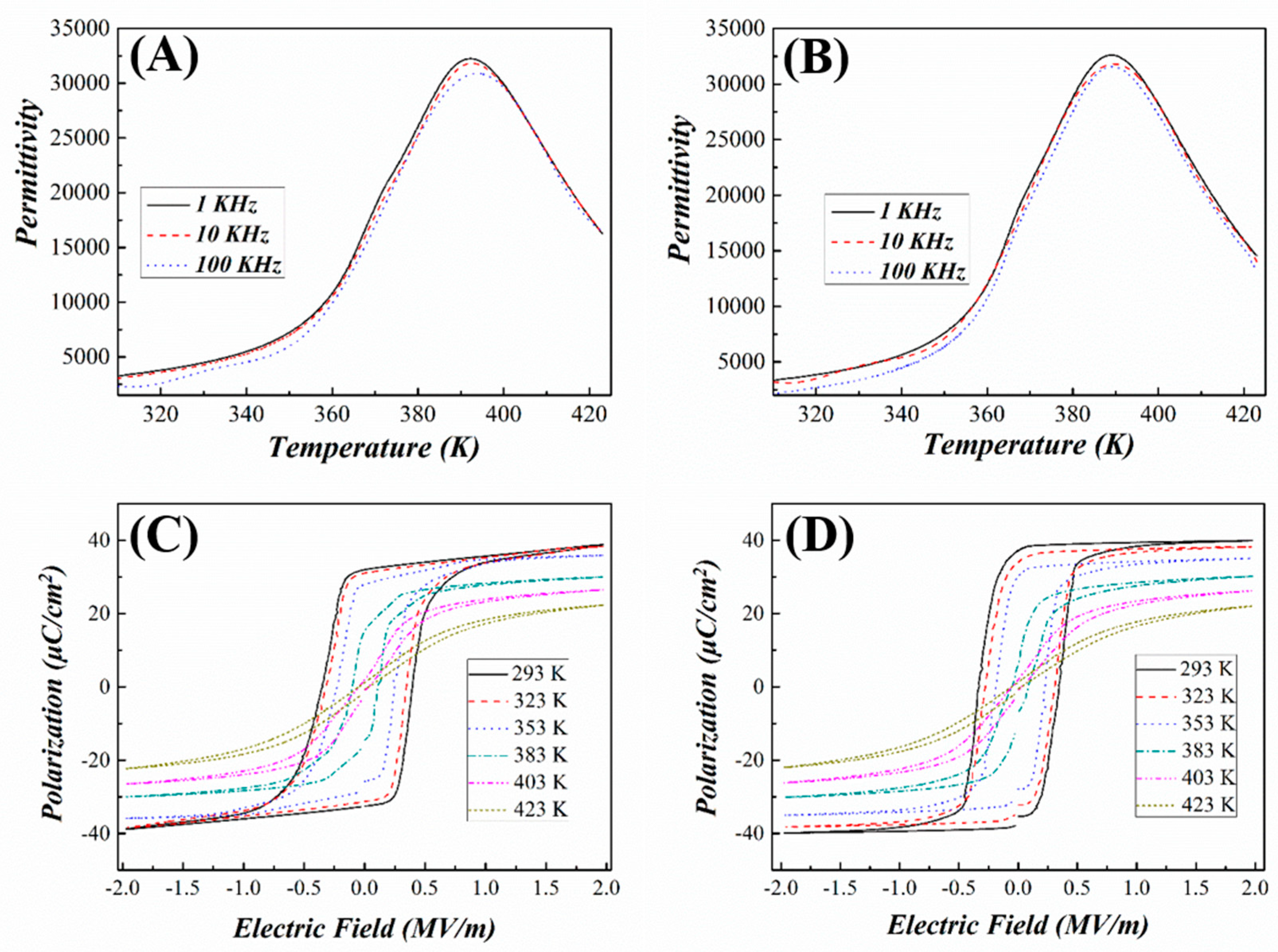
The temperature dependences of permittivities are depicted in Figure 2A,B. The permittivities versus temperature at three frequencies (1, 10 and 100 kHz) exhibit board peaks in the measured temperature range. The P–E hysteresis loops were measured at 10 Hz and at a 10 K interval in the temperature range of 293 K to 423 K and the representative plots of P–E loops are shown in Figure 2C,D.
At low temperatures, the shape of the loops is rather square due to the absence of grain boundaries in single crystals [18]. With the increasing temperature, the hysteresis loops for the two samples exhibit a transition from square loops to slim ones. At each temperature, the remnant polarization ( P r ) and spontaneous polarization ( P s ) along the [110] direction are smaller than that of the [111] direction, but the coercive field ( E c ) of [110] direction is slightly larger. There are eight equivalent polarization orientations along the [111] direction for rhombohedral relaxor ferroelectric PMN-27PT single crystals. When the electric field is applied on the sample, the dipoles will reorient along the electric field direction. While for the [110] direction, there are only two equivalent polar vectors along the [111] direction, which will rotate 35.5° toward the applied field direction of [110] with a designated domain engineered configuration “2R.” [19]. For this case, the macroscopic symmetry is mm2. In contrast, there is only one polar vector along the [111] direction for [111] poled ferroelectric crystals, thus it will form a monodomain state, designated as “1R”, exhibiting symmetry 3 m [19]. According to the domain engineered configurations, the polarization level derived from the hysteresis loops should be correlated [20].
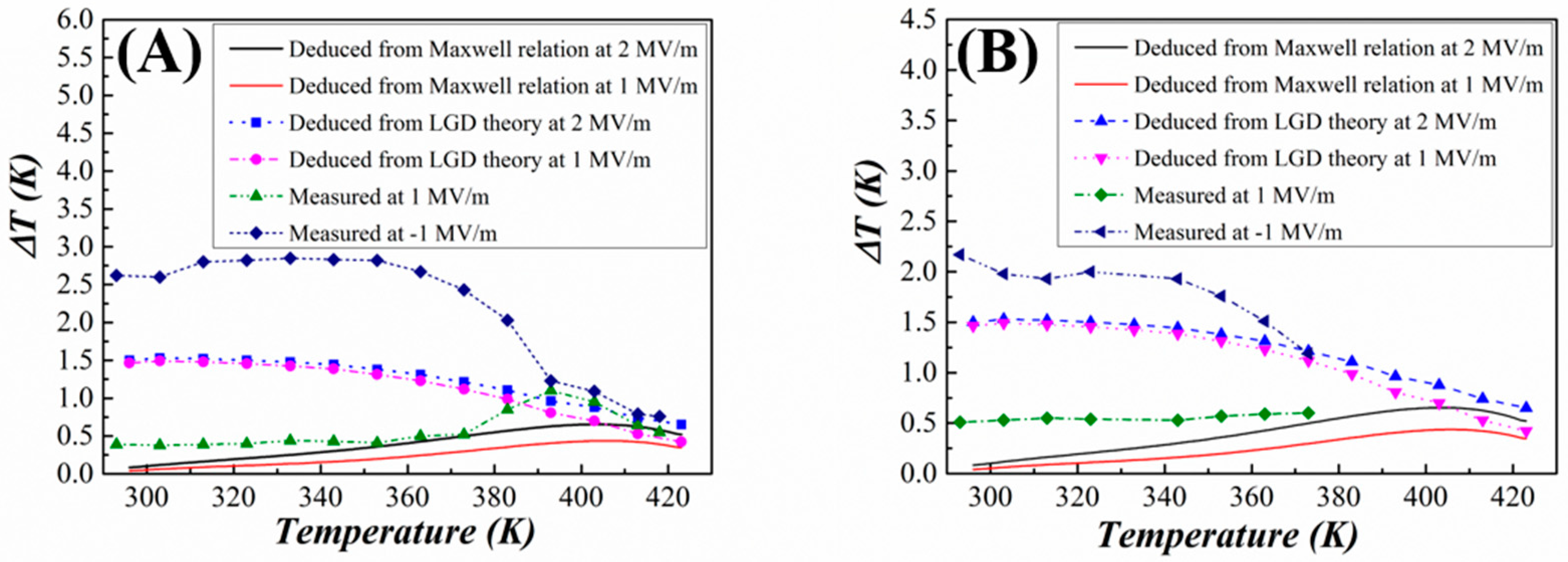
The ECE results obtained by indirect and direct ways are plotted in Figure 3. For the indirect method, the ECEs at 1 MV/m and 2 MV/m are present in the figures. For the ECE obtained indirectly, at the same electric field, the ECE calculated by the LGD theory is larger than that deduced by the Maxwell relation at any temperature. Moreover, the ECEs deduced via the Maxwell relation have peak values around the Curie temperature, about 400 K. The appearance of peak values is ascribed to the electric field induced phase transition from ferroelectric to paraelectric phase [21]. However, the ECEs calculated by the LGD theory decrease monotonically, even around the Curie temperature. For the ECEs obtained directly, the data measured at 1 MV/m and −1 MV/m are plotted respectively. Over the full testing temperature range, the measured data for the [110] direction sample at 1 MV/m are smaller below 383 K, but larger above 383 K than those calculated by the LGD theory, while the measured data of this sample are larger than those deduced by the Maxwell relation. For the [111] direction sample, due to the absence of the data at ΔT > 373 K, the existing ΔT are between the data obtained by the two indirect methods. For the data measured at −1 MV/m below 383 K, the results are much larger than and in sharp contrast to those deduced from the indirect methods. The ΔT of the [110] direction sample at −1 MV/m and 1 MV/m have almost the opposite variation tendency. The ΔT of this sample at −1 MV/m is much larger than those at 1 MV/m below 393 K, but almost the same above 393 K. We noted the theoretical calculation using thermodynamic theory for PMN-0.35PT [22], for the electric field without causing flipping of the electric domains, our results are consistent with the calculation.
It can be seen from the P–E hysteresis loops (Figure 2), that below the temperature of 383 K, the shape of the P–E loops for 0.73PMN–0.27PT crystals is rather square. In that case, the values of the remnant polarization ( P r ) are only slightly smaller than that of saturation polarization ( P s ). Thus, when the electric field is released, the polarization variation is very small. That is, the change in the ordering degree of dipoles is very small. Hence, the polarization entropy increases little, while the lattice vibration entropy slightly decreases under the adiabatic condition. Hence, the ECE caused by the polarization entropy variation (the first ECE signal) is not significant. During the same test run, when the applied electric field changes to −1 MV/m, the dipoles are flip-switched and orient along the reversed electric field. During this process, the dipoles have a remarkable rotation and a large polarization entropy variation comes up. The distinct appearance of the second ECE signal is attributed to this process. The phenomena can be illustrated as follows. For the electric field changes from +E to 0, the polarization changes from Ps to Pr, then the entropy change
Δ S 1 = 1 2 1 ε 0 C ( P r 2 P S 2 )
For the electric field changes from 0 to −E, Basso et al. observed an enhancement of ECE in P(VDF-TrFE) polymers [23], but no illustration was reported. Considering the ferroelectric system as a quasi-one dimensional harmonic oscillator, the free energy can be expressed in terms of the harmonic term plus higher order terms, in which the harmonic term is proportional to the square of the average value of the canonical coordinate of the B-site ion, i.e., <Ql>, which is corresponding to the order parameter-polarization in the Landau average field theory. For a displacive type ferroelectric, the polarization is proportional to the displacement of the ions. This means that the ionic displacement is proportional to the polarization. Now one can see that the ionic displacement changes from plus to minus when the electric field changes its sign, leading to the polarization changes from +P to −P. If the polarization changes from Pr to –Ps, the ionic displacement changes from ~+<Ql> to −<Ql>, totaled ~2<Ql>. Thus, the harmonic energy has a change of about four times of the original value if the change of displacement is directly from +Pr (~+Ps) to (−Ps). Thus, the isothermal entropy change will have a large enhancement compared with that when the electric field changes from E to 0. Therefore, a larger peak will be observed (shown in Figure 1). However, as shown in Figure 2, the P–E hysteresis loops have a transition from a square-like form to a slim form with the increasing temperature. The P r also becomes smaller and smaller with the increasing temperature. Then the entropy change in Equation (6) gets larger and leads to a large ECE signal. When the applied electric field was reversed to −1 MV/m, the displacement of B-site ion decreases, thus the second ECE signal becomes smaller as well. Therefore, as the temperature increases, the first ECE signal becomes larger compared with the second ECE signal during the same test process.
The calculation using the Maxwell relation is a convenient way to procure the ECE, and has been widely employed in procuring the ECE for crystals or polycrystalline materials [24], but it should be noted that the application of the Maxwell relation should be limited to continuous phase transition, and beyond the range of non-ergodicity. For the ECE deduced using the Maxwell relation, the temperature dependence of polarization P(T) is usually obtained by fitting the measured polarizations extracted from the P–E hysteresis loops at different temperatures. For instance, in this study, the P–E loops were gained at a 10 K interval. Within the two adjacent testing temperatures, the polarization can only be predicated by fitting the discrete data. Thus, the P vs T relationship cannot be determined accurately and this leads to errors for ( P T ) E [25]. Within a dynamic measurement of the ECE in an AC electric field, the finite polarization relaxation time has an impact on ( P T ) E and leads to errors for the quasi-static model [5,26].
The dielectric behavior of relaxor or normal ferroelectrics can be determined in terms of a universal Curie–Weiss law [27]:
1 ε 1 ε m = ( T T m ) γ C
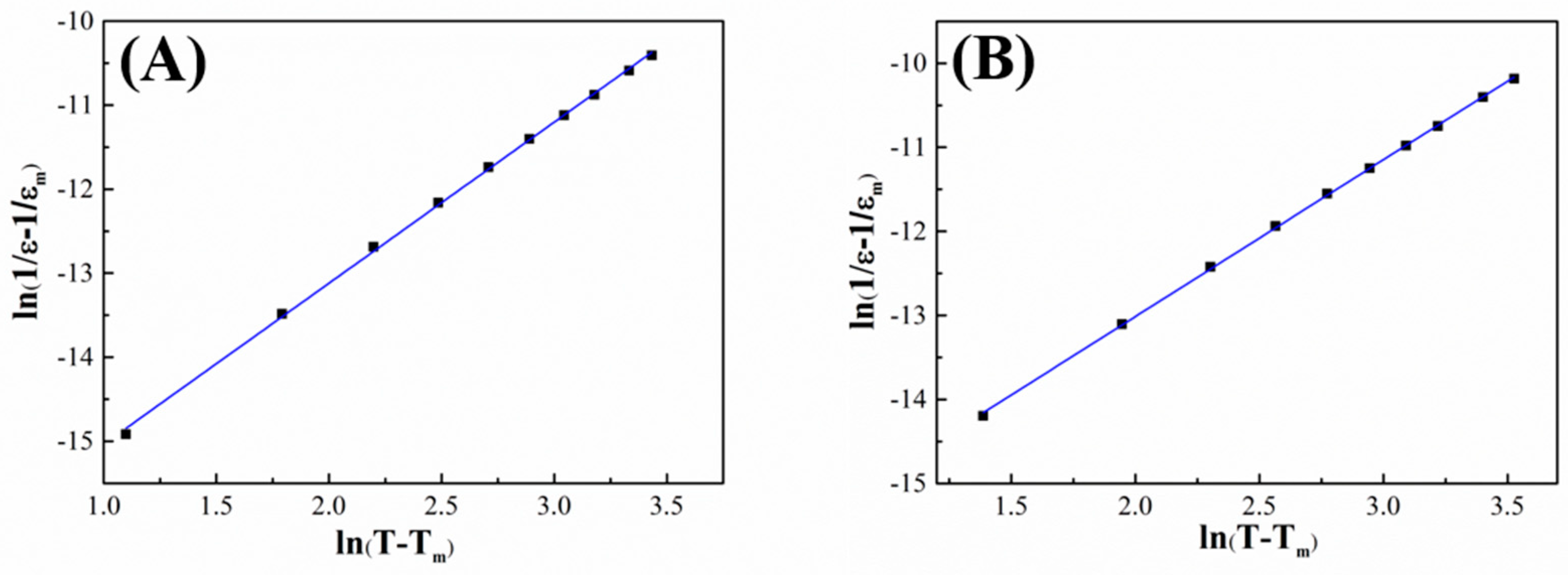
where ε m and T m are the maximum dielectric constant and the corresponding temperature observed in a wide temperature range around the phase transition point, ε and T are the dielectric constant and the corresponding temperature above the T m , C is the Curie-like constant, and γ is the exponent indicating the diffusiveness of the ferroelectric. Ideally, when γ = 1 , the material is a normal ferroelectric, but when γ = 2 , the ferroelectric is a relaxor ferroelectric. The relaxor ferroelectric behavior is increasing gradually with γ when γ is between 1 and 2. γ can be worked out via fitting the logarithmic plot of the reciprocal permittivity ( 1 ε 1 ε m ) as a function of temperature ( T T m ) , measured at the same frequency. As shown in Figure 4A,B, the γ of the reciprocal permittivity with respect to temperature was determined from the slope of the fitted straight line: γ = 1.92 for the [110] direction sample and 1.87 for the [111] direction sample. Thus, the two samples have strong relaxor ferroelectric behaviors. For the relaxor ferroelectrics, a glassy polarization mechanism was subsequently proposed with correlations between super-paraelectric moments leading to the development of effective non-ergodicity in a frozen state [28]. Then, for the relaxor ferroelectrics, the relaxation time of polarization also limited the accuracy of the ECE deduced by the Maxwell relation since the Maxwell relation is derived based on the assumption that the thermodynamic system is ergodic [29]. Typical non-ergodic systems make the systems with very low relaxation times. The measuring procedure itself changes the state of the material (the so-called memory effect), which influences the measurement results [30].
In a multi-domain material, the domain dynamics under the applied field reduce the excess entropy available for transfer to acoustic modes, consequently, reducing the ECE. To increase the accuracy of the indirect method, the system must be brought toward a single domain crystal, which can, in the first approximation, be achieved at the state of saturated polarization [31]. However, bulk crystal cannot sustain very high electric fields, so the single domain is difficult to form in the crystal.
As has been mentioned above, in the Gibbs free energy equation, the coefficient σ 1 was assumed approximately a linear temperature dependence as the usual expression for normal ferroelectric and σ 1 equals to T T 0 ε 0 C . For normal ferroelectrics, the paraelectric phase appears instantly above the Curie temperature, but the ferroelectric phase still exists above the Curie temperature in relaxor ferroelectrics. According to Pirc’s work [32], in relaxor ferroelectrics, the value of ε 0 C is not constant and expected to be a function of temperature because the coefficient σ 1 must remain positive at all temperatures. Thus, large errors occur when deducing the Curie constant C. Moreover, the existence of domain walls, domain structure, domain wall mobility and defect dipoles will impact the polarization [33], and cause error to the ECEs deduced from the Gibbs free energy equation.
For the ECE measured directly, the main source of measurement error is due to the heat that dissipates through objects attached to the sample and surrounding around the sample, e.g., the thermocouple and the electrode wires. However, due to fast internal thermal response, the method used in this study has a sufficient accuracy [34]. Therefore, the ECE measured directly is considered to be the closest to the real situation.

4. Conclusions

In conclusion, a large ECE was procured through reversing the applied electric field, which is larger than that by applying the electric field in the same direction for 0.73PMN–0.27PT relaxor ferroelectric crystals. The directly measured results are larger than those calculated from the Maxwell relation and even larger than those deduced using the LGD theory in the lower temperature range. The flipping of electric domains can be used to further enhance the ECE in ferroelectrics.

Author Contributions

Conceptualization, S.-G.L. and B.L. (Biao Lu); methodology, B.L. (Biao Lu); software, X.L. and Y.Y.; validation, B.L. (Biao Lu); X.J., Y.Y., T.T., B.L. (Bo Liang), H.L. and S.-G.L.; formal analysis, B.L. (Biao Lu); investigation, B.L. (Biao Lu); sources, H.L.; writing—original draft preparation, B.L. (Biao Lu); writing—review and editing, S.-G.L.; supervision, S.-G.L.; funding acquisition, S.-G.L. All authors have read and agreed to the published version of the manuscript.

Funding

This research was funded by the Natural Science Foundation of China (Grant No. 51372042, 51872053), Guangdong Provincial Natural Science Foundation (2015A030308004), the NSFC-Guangdong Joint Fund (Grant No. U1501246) and the Dongguan Frontier Research Project (2019622101006).

Conflicts of Interest

The authors declare no conflict of interest.

References

  1. Lines, M.E.; Glass, A.M. Principles and Applications of Ferroelectrics and Related Materials; Clarendon Press: Oxford, UK, 1977. [Google Scholar]
  2. Pakhomov, O.V.; Karmanenko, S.F.; Semenov, A.A.; Starkov, A.S.; Es’kov, A.V. Thermodynamic estimation of cooling efficiency using an electrocaloric solid-state line. Tech. Phys. 2010, 55, 1155–1160. [Google Scholar] [CrossRef]
  3. Mischenko, A.S.; Zhang, Q.; Scott, J.F.; Whatmore, R.W.; Mathur, N.D. Giant electrocaloric effect in thin-film PbZr0.95Ti0.05O3. Science 2006, 311, 1270–1271. [Google Scholar] [CrossRef] [PubMed] [Green Version]
  4. Neese, B.; Chu, B.; Lu, S.G.; Wang, Y.; Furman, E.; Zhang, Q.M. Large electrocaloric effect in ferroelectric polymers near room temperature. Science 2008, 321, 821–823. [Google Scholar] [CrossRef] [PubMed]
  5. Liu, Y.; Scott, J.F.; Dkhil, B. Direct and indirect measurements on electrocaloric effect: Recent developments and perspectives. Appl. Phys. Rev. 2016, 3, 031102. [Google Scholar] [CrossRef] [Green Version]
  6. Ma, Y.B.; Novak, N.; Koruza, J.; Yang, T.Q.; Albe, K.; Xu, B.X. Enhanced electrocaloric cooling in ferroelectric single crystals by electric field reversal. Phys. Rev. B 2016, 94, 100104. [Google Scholar] [CrossRef] [Green Version]
  7. Zhang, T.F.; Tang, X.G.; Ge, P.Z.; Liu, Q.X.; Jiang, Y.P. Orientation related electrocaloric effect and dielectric phase transitions of relaxor PMN-PT single crystals. Ceram. Int. 2017, 43, 16300–16305. [Google Scholar] [CrossRef]
  8. Wu, H.H.; Cohen, R.E. Electric-field-induced phase transition and electrocaloric effect in PMN-PT. Phys. Rev. B 2017, 96, 054116. [Google Scholar] [CrossRef] [Green Version]
  9. Sebald, G.; Seveyrat, L.; Guyomar, D.; Lebrun, L.; Guiffard, B.; Pruvost, S. Electrocaloric and pyroelectric properties of 0.75Pb(Mg1/3Nb2/3)O3-0.25PbTiO3 single crystals. J. Appl. Phys. 2006, 100, 124112. [Google Scholar] [CrossRef]
  10. Lu, B.; Yao, Y.B.; Jian, X.D.; Tao, T.; Liang, B.; Zhang, Q.M.; Lu, S.G. Enhancement of the electrocaloric effect over a wide temperature range PLZT ceramics by doping with Gd3+ and Sn4+ ions. J. Eur. Ceram. Soc. 2019, 39, 1093–1102. [Google Scholar] [CrossRef]
  11. Kutnjak, Z.; Rožič, B. Indirect and direct measurements of the electrocaloric effect. In Electrocaloric Material; Correia, T., Zhang, Q., Eds.; Springer: Berlin/Heidelberg, Germany, 2014; pp. 147–182. [Google Scholar]
  12. Yao, H.; Ema, K.; Garland, C.W. Nonadiabatic scanning calorimeter. Rev. Sci. Instrum. 1998, 69, 172–178. [Google Scholar] [CrossRef]
  13. Lu, S.G.; Zhang, Q.M. Electrocaloric materials for solid state refrigeration. Adv. Mater. 2009, 21, 1983–1987. [Google Scholar] [CrossRef]
  14. Haun, M.J.; Furman, E.; McKinstry, H.A.; Cross, L.E. Thermodynamic theory of the lead zirconate-titanate solid solution system, part II: Tricritical behavior. Ferroelectrics 1989, 99, 27–44. [Google Scholar] [CrossRef]
  15. Haun, M.J.; Furman, E.; Jang, S.J.; Cross, L.E. Thermodynamic theory of the lead zirconate-titanate solid solution system, part I: Phenomenology. Ferroelectrics 1989, 99, 13–25. [Google Scholar] [CrossRef]
  16. Baerwald, H.G. Thermodynamic theory of ferroelectric ceramics. Phys. Rev. 1957, 105, 480–486. [Google Scholar] [CrossRef]
  17. Lu, S.G.; Rozic, B.; Kutnjak, Z.; Zhang, Q.M. Electrocaloric effect in ferroelectric P(VDF-TrFE) copolymers. Integr. Ferroelectr. 2011, 125, 176–185. [Google Scholar] [CrossRef]
  18. Marincel, D.M.; Zhang, H.R.; Kumar, A.; Jesse, S.; Kalinin, S.V.; Rainforth, W.M.; Reaney, I.M.; Randall, C.A.; Trolier-McKinstry, S. Influence of a single grain boundary on domain wall motion in ferroelectrics. Adv. Funct. Mater. 2014, 24, 1409–1417. [Google Scholar] [CrossRef]
  19. Zhang, S.; Sherlock, N.P.; Meyer, R.J.; Shrout, T.R. Crystallographic dependence of loss in domain engineered relaxor-PT single crystals. Appl. Phys. Lett. 2009, 94, 162906. [Google Scholar] [CrossRef] [Green Version]
  20. Davis, M.; Damjanovic, D.; Hayem, D.; Setter, N. Domain engineering of the transverse piezoelectric coefficient in perovskite ferroelectrics. J. Appl. Phys. 2005, 98, 014102. [Google Scholar] [CrossRef] [Green Version]
  21. Shi, Y.P.; Soh, A.K. Modeling of enhanced electrocaloric effect above the Curie temperature in relaxor ferroelectrics. Acta Mater. 2011, 59, 5574–5583. [Google Scholar] [CrossRef] [Green Version]
  22. Khassaf, H.; Mantese, J.V.; Bassiri-Gharb, N.; Kutnjak, Z.; Alpay, S.P. Perovskite ferroelectrics and relaxor-ferroelectric solid solutions with large intrinsic electrocaloric response over broad temperature ranges. J. Mater. Chem. C 2016, 4, 4763. [Google Scholar] [CrossRef] [Green Version]
  23. Basso, V.; Gerard, J.-F.; Pruvost, S. Doubling the electrocaloric cooling of poled ferroelectric materials by bipolar cycling. Appl. Phys. Lett. 2014, 105, 052907. [Google Scholar] [CrossRef]
  24. Lu, S.G.; Zhang, Q.M. Large electrocaloric effect in relaxor ferroelectrics. J. Adv. Dielectr. 2012, 2, 123011. [Google Scholar] [CrossRef]
  25. Lu, B.; Li, P.L.; Tang, Z.H.; Yao, Y.B.; Gao, X.S.; Kleemann, W.; Lu, S.G. Large electrocaloric effect in relaxor ferroelectric and antiferroelectric lanthanum doped lead zirconate titanate ceramics. Sci. Rep. 2017, 7, 45335. [Google Scholar] [CrossRef] [PubMed] [Green Version]
  26. Hanrahan, B.; Espinal, Y.; Neville, C.; Rudy, R.; Rivas, M.; Smith, A.; Kesim, M.T.; Alpay, S.P. Accounting for the various contributions to pyroelectricity in lead zirconate titanate thin films. J. Appl. Phys. 2018, 123, 124104. [Google Scholar] [CrossRef]
  27. Bokov, A.A.; Ye, Z.G. Dielectric relaxation in relaxor ferroelectrics. J. Adv. Dielectr. 2012, 2, 1241010. [Google Scholar] [CrossRef]
  28. Viehland, D.; Jang, S.J.; Cross, L.E.; Wuttig, M. Deviation from Curie-Weiss behavior in relaxor ferroelectrics. Phys. Rev. B 1992, 46, 8003. [Google Scholar] [CrossRef]
  29. Lu, S.G.; Rožič, B.; Zhang, Q.M.; Kutnjak, Z.; Pirc, R.; Lin, M.R.; Li, X.Y.; Gorny, L.J. Comparison of directly and indirectly measured electrocaloric effect in the relaxor ferroelectric polymers. Appl. Phys. Lett. 2010, 97, 202901. [Google Scholar] [CrossRef]
  30. Valant, M. Electrocaloric materials for future solid-state refrigeration technologies. Prog. Mater. Sci. 2012, 57, 980–1009. [Google Scholar] [CrossRef]
  31. Birks, E.; Dunce, M.; Peräntie, J.; Hagberg, J.; Sternberg, A. Direct and indirect determination of electrocaloric effect in Na0.5Bi0.5TiO3. J. Appl. Phys. 2017, 121, 224102. [Google Scholar] [CrossRef] [Green Version]
  32. Pirc, R.; Kutnjak, Z.; Blinc, R.; Zhang, Q.M. Upper bounds on the electrocaloric effect in polar solids. Appl. Phys. Lett. 2011, 98, 021909. [Google Scholar] [CrossRef]
  33. Weyland, F.; Bradesko, A.; Ma, Y.B.; Koruza, J.; Xu, B.X.; Albe, K.; Rojac, T.; Novak, N. Impact of polarization dynamics and charged defects on the electrocaloric response of ferroelectric Pb(Zr,Ti)O3 ceramics. Energy Technol. 2018, 6, 1518–1525. [Google Scholar] [CrossRef]
  34. Lu, S.G.; Rozic, B.; Zhang, Q.M.; Kutnjak, Z.; Li, X.Y.; Furman, E.; Gorny, L.J.; Lin, M.R.; Malic, B.; Kosec, M.; et al. Organic and inorganic relaxor ferroelectrics with giant electrocaloric effect. Appl. Phys. Lett. 2010, 97, 162904. [Google Scholar] [CrossRef]
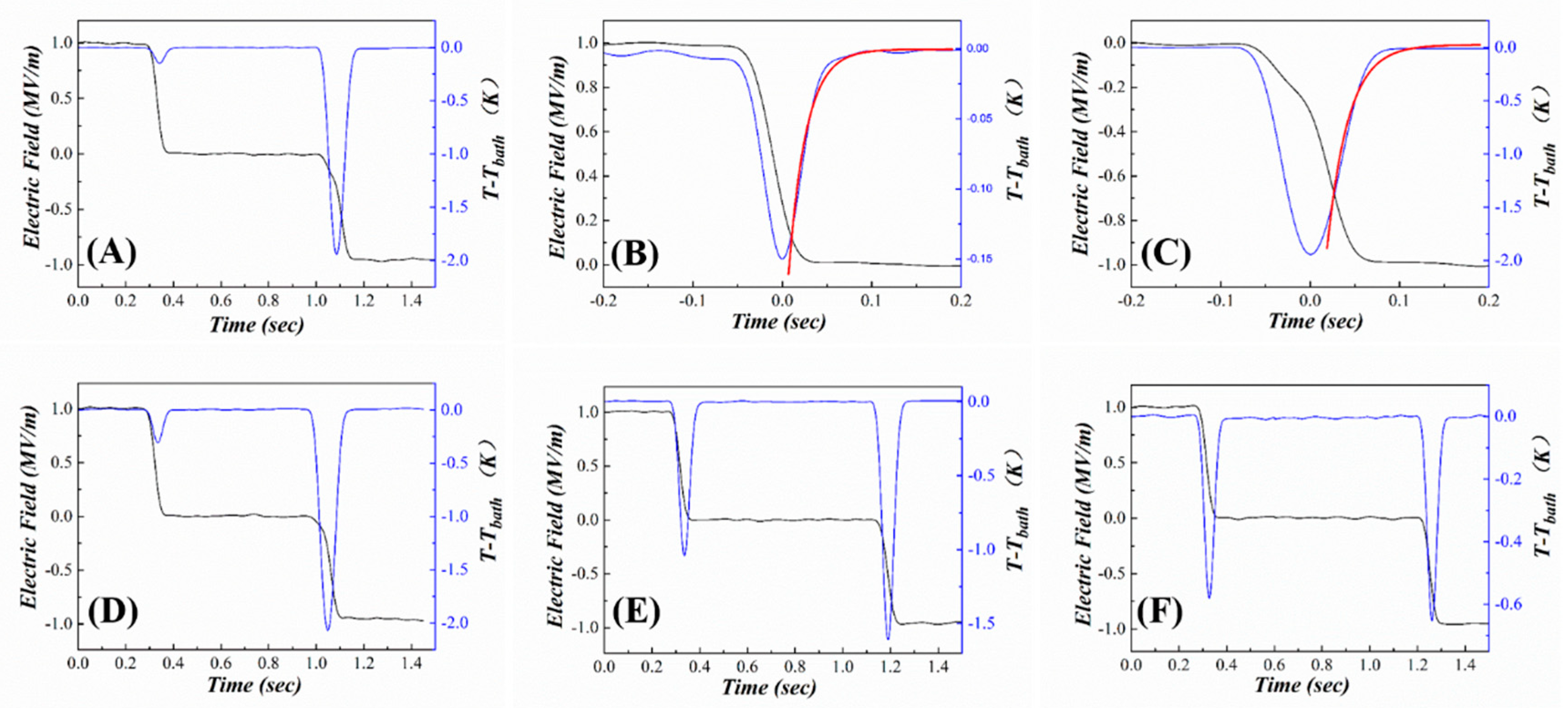
Figure 1. The electrocaloric effect (ECE) signals of [110] direction of PMN-PT single crystal at 1 MV/m. (A) ECE measured @ 296 K; (B) Fitting of 1st signal in Figure 1A; (C) Fitting of 2nd signal in Figure 1A; (DF) ECE measured @ 353, 383, and 418 K, respectively.
Crystals 10 00451 g001
Figure 2. Permittivity and polarization–electric fields (P–E) hysteresis loop as a function of temperature for PMN-PT single crystals with the [110] direction (A,C) and [111] direction (B,D).
Crystals 10 00451 g002
Figure 3. Temperature changes (ΔT) for the [110] direction (A) and [111] direction (B) obtained from direct measurements, the Maxwell relation, and the LGD theory.
Crystals 10 00451 g003
Figure 4. Reciprocal permittivity ( 1 ε 1 ε m ) (at 1 kHz) as a function of temperature (T T m ) for crystals with a direction of [110] (A), and [111] (B).
Crystals 10 00451 g004