Article

Switchable Lens Design for Multi-View 2D/3D Switching Display with Wide-Viewing Window

1
School of Electronics Engineering, Kyungpook National University, Daegu 41566, Korea
2
Electronics and Telecommunication Research Institute, Daejeon 61012, Korea
*
Author to whom correspondence should be addressed.
Crystals 2020, 10(5), 418; https://doi.org/10.3390/cryst10050418
Submission received: 15 March 2020 / Revised: 16 May 2020 / Accepted: 22 May 2020 / Published: 24 May 2020
(This article belongs to the Special Issue Organic Optoelectronic Materials)

Abstract

:
We improved the three-dimensional (3D) crosstalk level of multi-view 3D displays using a lens array with small f-number, thereby facilitating a wide 3D viewing window. In particular, we designed a polarization-dependent-switching liquid crystal (LC)-based gradient refractive index (GRIN) lens array that could be switched between 2D and 3D viewing modes. For the GRIN lens with a small f-number (1.08), we studied the effect of the interfacial curvature between the plano-concave isotropic polymer layer and the plano-convex birefringent LC layer on the aberration properties. We examined the conventional spherical, quadratic polynomial aspherical, and a high-order (fourth-order) polynomial aspherical curvature. For the high-order polynomial aspherical curvature, the achievable transverse spherical aberration (TSA = 10.2 µm) was considerably lower than that with the spherical (TSA = 100.3 µm) and quadratic polynomial aspherical (TSA = 30.4 µm) curvatures. Consequently, the angular luminance distributions for each view were sharper for the high-order polynomial interfacial curvature. We designed multi-view (43-view) 3D displays using the arrays of switchable LC lenses with different curvatures, and the average adjacent crosstalk levels within the entire viewing window (50°) were 68.5%, 73.3%, and 60.0% for the spherical, quadratic polynomial aspherical, and high-order polynomial aspherical curvatures, respectively.

Graphical Abstract

1. Introduction

Three-dimensional (3D) displays enhance viewer experience by providing 3D depth information of objects as opposed to 2D displays. Among several approaches for representing 3D images with conventional 2D display panels, autostereoscopic 3D display technology based on stereo-channel separation technology can convey 3D information to viewers without requiring the use of glasses [1,2,3,4]. For the achievement of stereo-channel separation, the front of the display panel is equipped with optical devices, such as microlens arrays (MLAs) and parallax barriers that can periodically channel rays emitted from each pixel toward an optimal viewpoint [5,6,7,8]. In the case of mobile displays, which require high optical efficiency for conserving battery power and high-resolution panels because of the relatively short viewing distance, optically efficient MLAs rather than parallax barriers are preferred. Although autostereoscopic 3D display technology involves the use of a limited number of 3D depth cues, such as binocular parity and motion parallax, it facilitates the efficient conversion of conventional 2D displays into 3D displays without increasing the display volume for 3D mobile display applications. In autostereoscopic 3D displays, the vergence-accommodation conflict can be avoided by substantially increasing the angular resolution of 3D views similar to super-multi-view 3D displays [9,10,11,12]. However, these approaches are inevitably accompanied by reduced 3D image resolution; thus, a high-resolution display panel is necessary. However, autostereoscopic 3D displays with a high-resolution panel have the problem of severe 3D crosstalk because of the low pixel pitch [13]. To meet market demands, autostereoscopic 3D displays should have the capability to deliver high-resolution 2D images as well. In addition, autostereoscopic 3D displays should be switchable between 2D and 3D viewing modes for accelerating their commercialization, and several researchers are actively involved with the development of active switching lenses for 2D display panels [14,15].
For the development of 2D/3D switchable multi-view displays, a lens array with switchable ray focusing can be developed by exploiting the birefringent properties of liquid crystals (LCs); an LC-based gradient refractive index (GRIN) lens array with switchable ray-focusing can be developed. One method for realizing switchable ray-focusing is to use the electrically switchable birefringence of the LC with the geometrically patterned electric field distribution produced by patterned electrodes [16,17,18,19,20,21,22,23,24]. However, for mobile displays, owing to the relatively short viewing distance, a lens array with a very small f-number should be developed to provide a wide 3D viewing window. For a small f-number, the LC layer thickness in the LC GRIN lens array should be large, increasing the switching voltage and time required to form the fringe electric field. For high-resolution mobile panels, because of the use of periodically patterned electrodes, the lens fill factor of the LC-based GRIN lens array decreases considerably with a decrease in the lens pitch.
Another method for realizing switchable ray focusing is to exploit the birefringent properties of the LC, but without electrically switching the LC in an LC-based GRIN lens. The lens structure comprises two parts: an LC-based GRIN lens and an electrically switchable polarization-switching layer used to control the incident polarization state [25,26,27,28,29]. The polarization-dependent-switching LC GRIN lens has a stacked structure comprising a plano-concave isotropic polymer layer and a plano-convex birefringent LC layer. In this structure, depending on the incident polarization state, the index matching or index mismatching condition can be selected for the two stacked optical layers for achieving the defocusing state or periodic focusing state; the incident polarization state can be electrically controlled through the underlying polarization control layer. Thus, the polarization-dependent-switching LC GRIN lens has a twofold structure: a polarization-switching layer for electrically switching the incident polarization state and an LC GRIN lens that acts as a switchable lens. They have a very fast response time, low driving voltage, and ideal lens profile, even for the lenses with small f-numbers. However, compared with conventional passive plano-convex lens arrays used in autostereoscopic 3D displays without the 2D/3D mode conversion function, the aberration problem is relatively more severe for a switchable LC GRIN lens with flat surfaces because of the additional ray distortion at the air-substrate interface [30]; the problem worsens for lenses with a considerably smaller f-number required for mobile 3D displays, resulting in high 3D crosstalk levels. Compared with approaches involving the direct electrical switching of the LC layer in an LC GRIN lens, the polarization-dependent-switching LC GRIN lens offers advantages for a small-f-number lens: the ray-focusing properties can be precisely controlled by optimizing the interfacial curvature between the plano-concave isotropic polymer layer and the plano-convex birefringent LC layer since the LC has a homogeneously planar geometry, as opposed to the complex GRIN LC profile in the electrically switchable LC GRIN lenses.
In this study, to resolve the lens aberration problem, which is severe for a small f-number lens in 2D/3D switchable autostereoscopic mobile displays with a wide 3D viewing window, we investigated the effects of the interfacial curvature on the aberration properties of the polarization-dependent-switching LC GRIN lens. Furthermore, we examined the effects on the 3D crosstalk level by implementing switchable lens arrays with different interfacial curvatures on high-resolution mobile panels. Aspherical curvatures—a quadratic polynomial aspherical curvature and a high-order (fourth-order) polynomial aspherical curvature—were considered for investigating the ideal lens curvature profiles for the LC GRIN lens, and they were compared with the conventional spherical curvature. Finally, we achieved both considerably low aberration and low 3D crosstalk level with the polarization-dependent-switching LC GRIN lens having a high-order polynomial aspherical interfacial curvature for a small f-number (= 1.08) lens. The 3D crosstalk levels were evaluated by assuming a high-resolution (750.6 ppi) mobile panel, and the switchable lens arrays were designed for super-multi-view 3D viewing conditions with a viewing distance of 500 mm, a viewing window of 50°, and a total of 43 viewpoints. The average value of adjacent-view crosstalk levels was 60.0% for the high-order polynomial aspherical curvature, which was lower than those of the spherical and quadratic polynomial aspherical curvatures by more than 8.5% and 13.3%, respectively.

2. Aberration Properties of LC-Based GRIN Lens Array Switched to Focused State

2.1. Operation Principle and Aberration Properties of LC-Based GRIN Lens

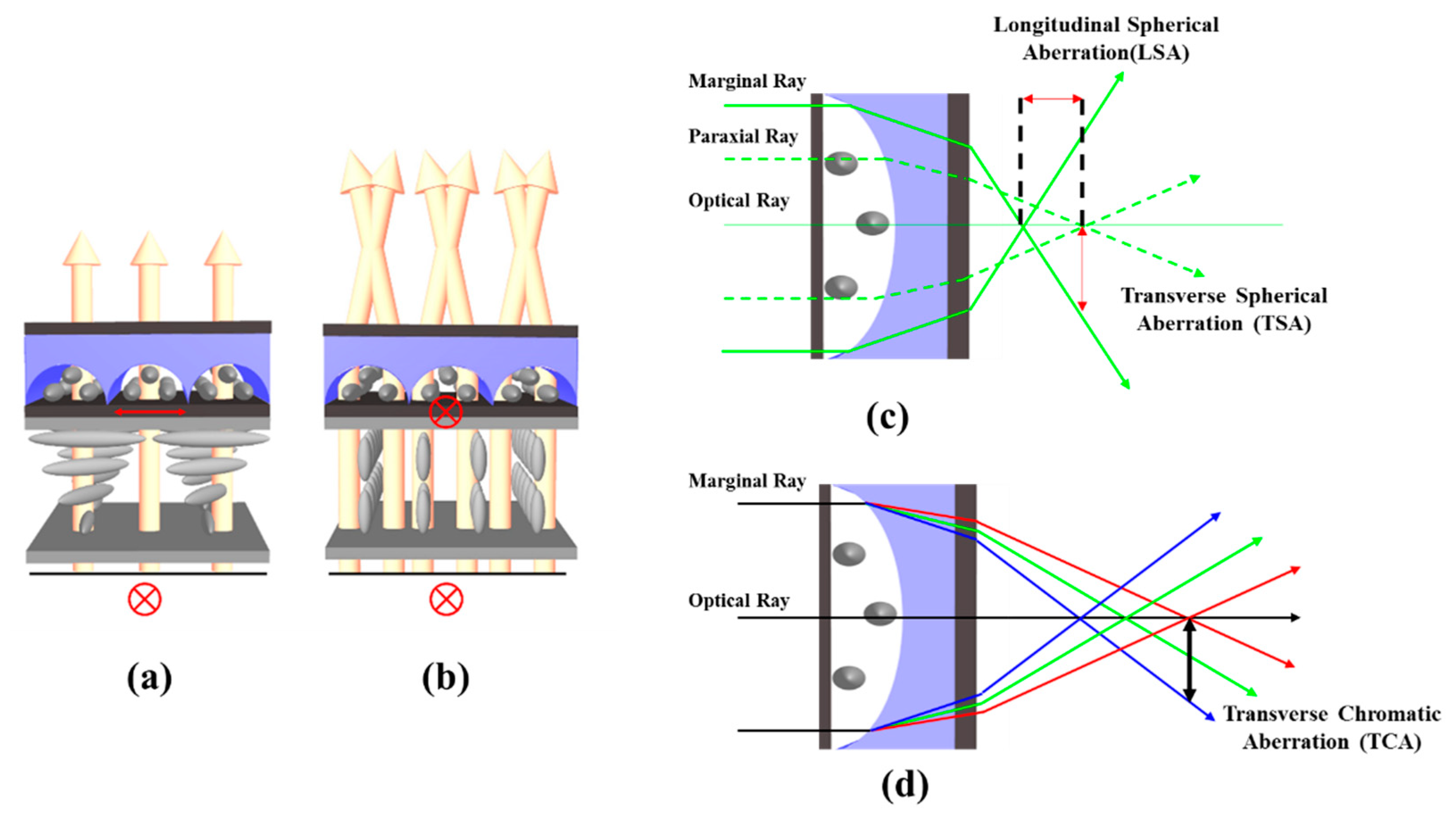
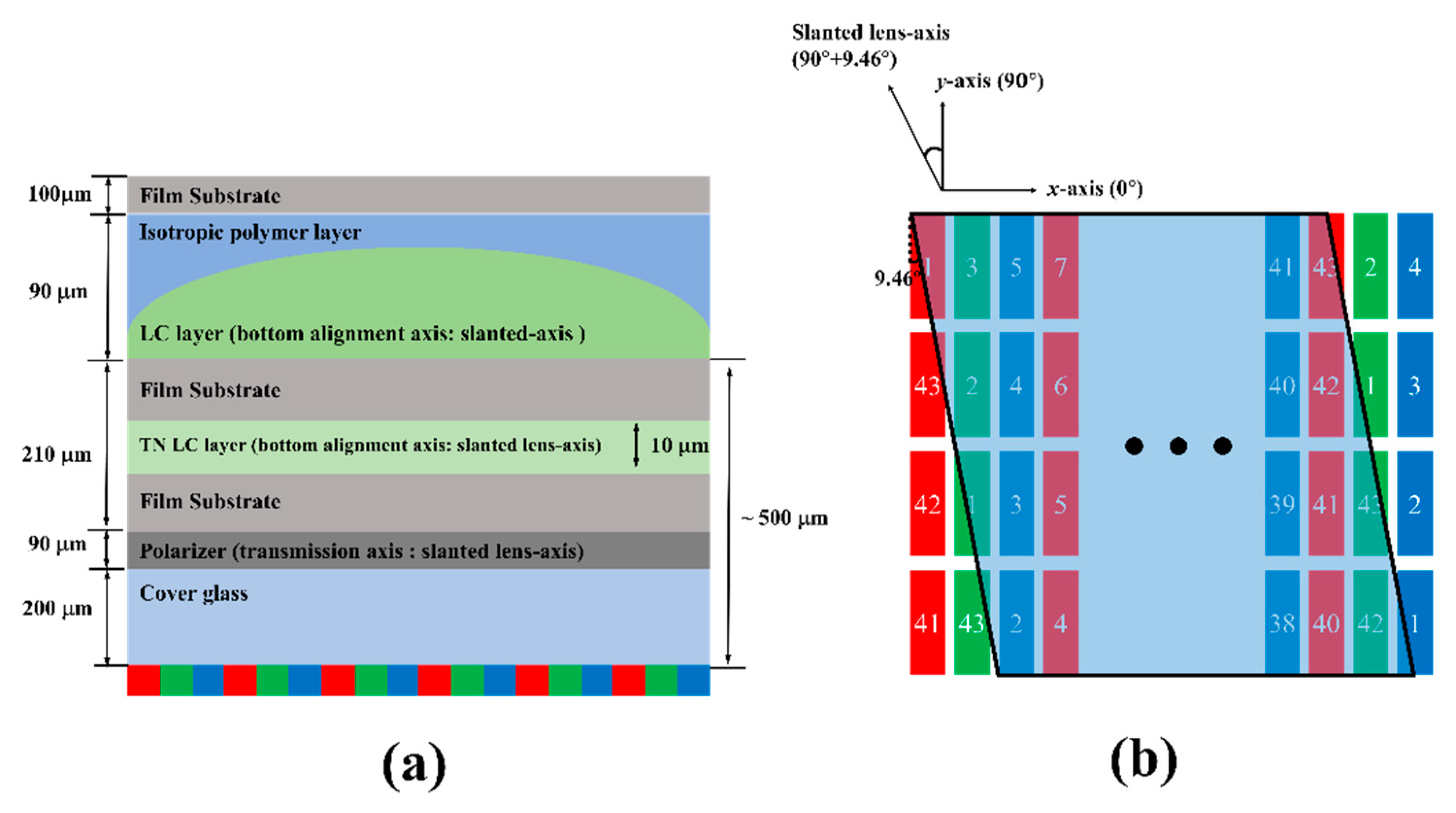
Figure 1a,b show the operating principle of the polarization-dependent-switching LC GRIN lens array. The lens array is divided into a polarization-switching layer through which the incident polarization state can be controlled and an LC GRIN lens array that can be optically switched to the periodic focusing or defocusing mode according to the incident polarization state. The LC GRIN lens array has two flat surfaces at the entrance and exit planes of the device structure, where the plano-convex LC layer is formed below the plano-concave isotropic polymer. The refractive index (np) of the isotropic polymer is identical to the ordinary refractive index (no) of the LC layer. However, the extraordinary refractive index (ne) is larger than np. As shown in Figure 1a, when the incident polarization state is perpendicular to the alignment axis of the LC layer, the incident light is not refracted according to index-matching conditions (no = np), and the structure operates in the defocusing state (2D display mode). By contrast, as shown in Figure 1b, when the polarization state of the incident light is parallel to the alignment axis of the LC layer, the incident light is periodically refracted owing to the index-mismatching (ne > np) condition, and the structure operates in the focusing state (3D display mode). The polarization-switching layer controls the incident polarization state according to the applied voltage. Thus, the stacked module can be switched between the defocusing and focusing modes in a 2D/3D switchable multi-view display.
Figure 1c shows the aberration properties of the polarization-dependent-switching LC GRIN lens array. The spherical aberration of the lens array can be divided into transverse spherical aberration (TSA) and longitudinal spherical aberration (LSA) induced by the difference in the focal length formed by the marginal rays and paraxial rays. Ray distortion caused by the TSA of the LC GRIN lens array can sensitively affect the 3D crosstalk level because of the broad luminance distribution at each viewpoint, resulting from ray distortion in the 3D mode. As shown in Figure 1c, the polarization-dependent-switching LC GRIN lens array involves additional ray refraction at the flat air-substrate interface, unlike a conventional passive lens array with the plano-convex surface geometry. In particular, the additional refraction further increases the TSA and LSA in a smaller f-number lens array compared with those of the plano-convex-shaped passive lens. This implies that the aberration values and 3D crosstalk levels of an LC GRIN lens designed for 2D/3D switchable mobile displays would be high. This information should be considered when designing the switchable lens [30].
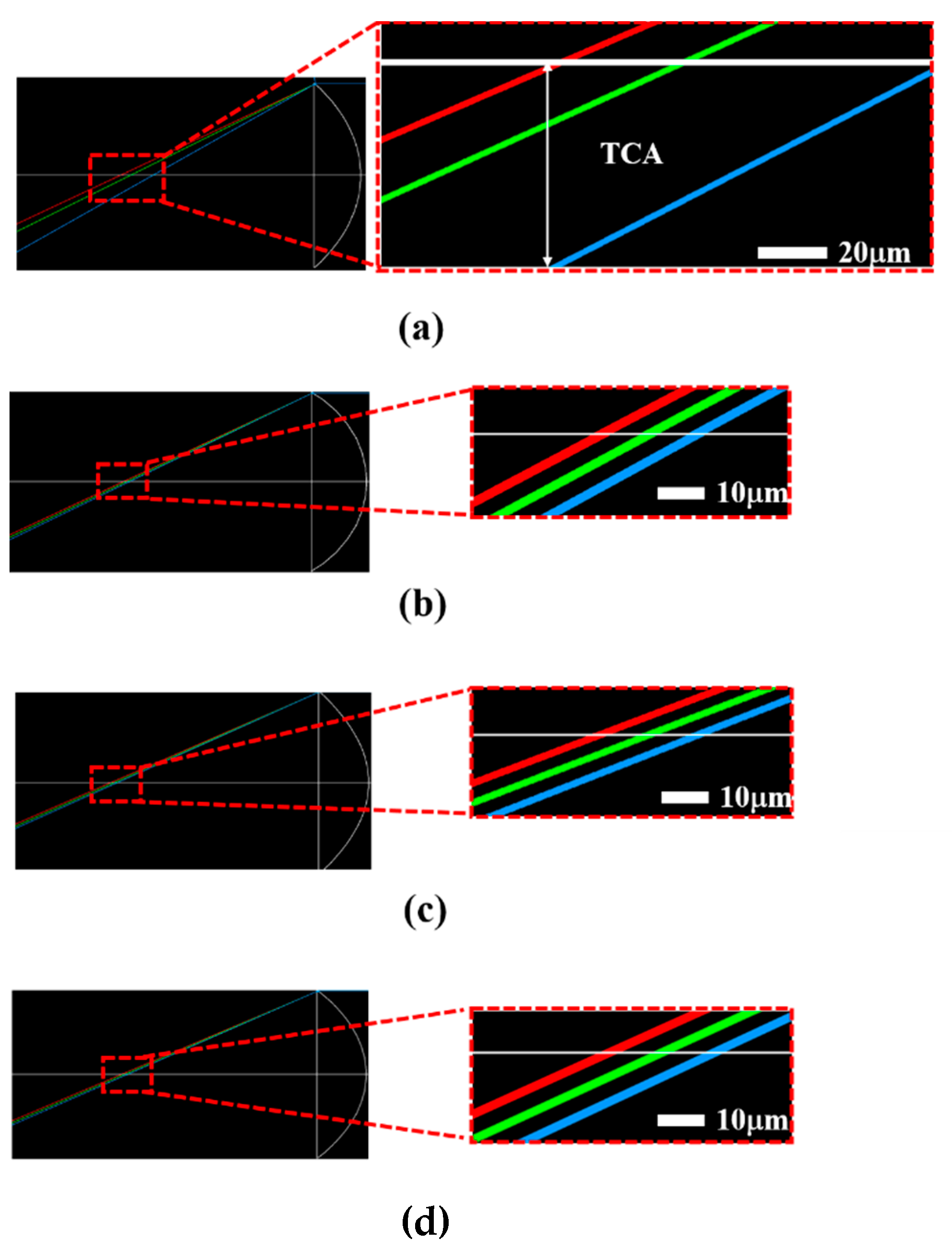
In designing the switchable LC GRIN lens array exhibiting an effectively reduced aberration property, the chromatic aberration, induced by the material dispersion, needs to be also considered [31]. Under the normal dispersion condition of the wavelength-dependent refractive index property of general optical materials, the focal length of a blue-colored light becomes shorter than that of a red-colored light as shown in Figure 1d. Like the spherical aberration, the chromatic aberration can also be divided into transverse chromatic aberration (TCA) and longitudinal chromatic aberration (LCA). Between both chromatic aberration effects, reducing the TCA effect is more important for achieving an improved 3D crosstalk level, especially in designing a small f-number lens [31]. However, unlike the switchable LC lens that forms GRIN profiles within the LC layer operated by fringe fields [16,17,18,19,20,21,22,23,24], the TCA effect of the polarization-dependent-switching LC GRIN lens array on the focusing properties can be effectively reduced by properly choosing the optical materials used for the plano-convex and plano-concave layers. The TCA effect by the material dispersion of the plano-convex LC lens part can be compensated by the TCA effect by the material dispersion of the plano-concave isotropic polymer lens part [32].
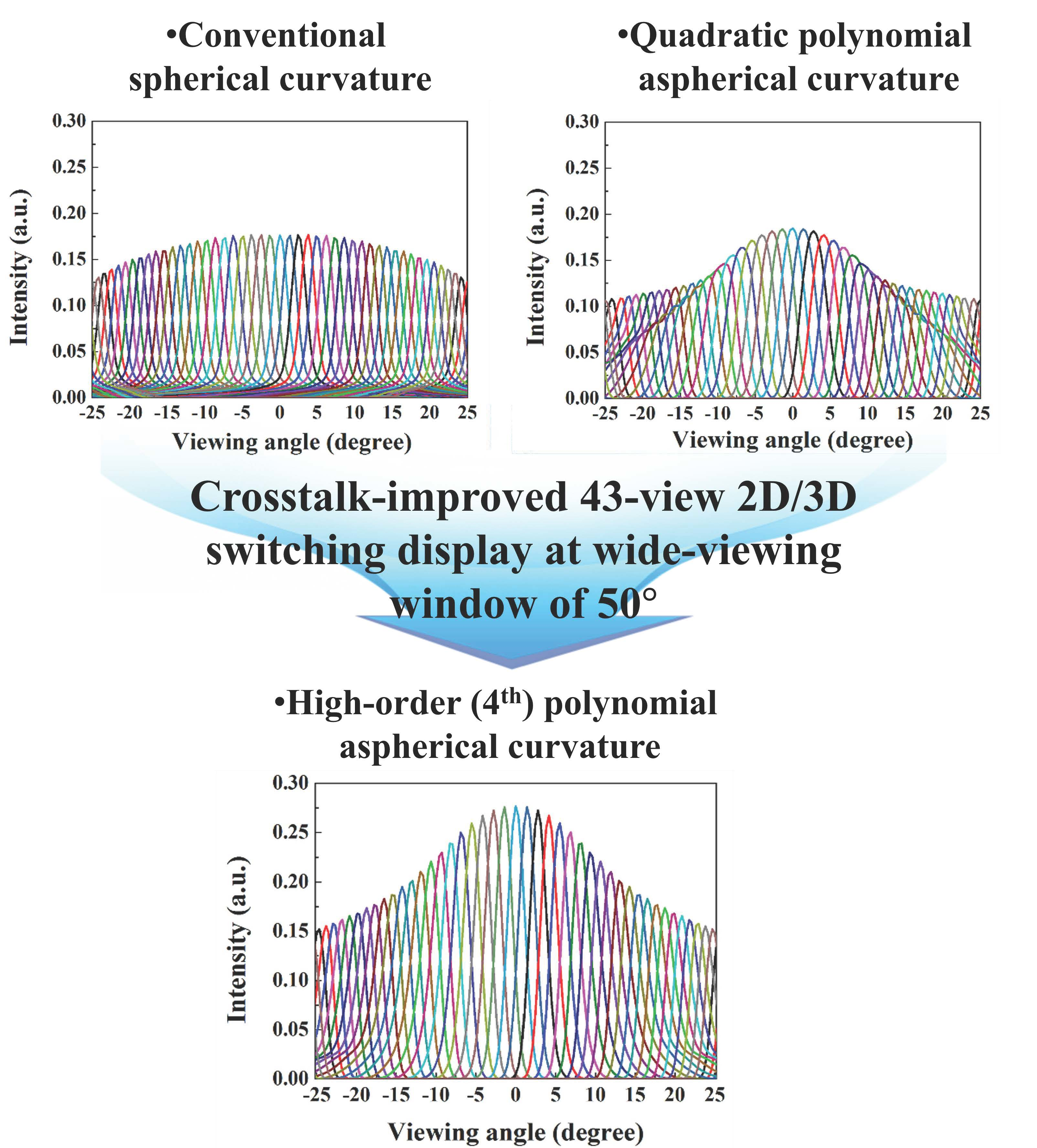
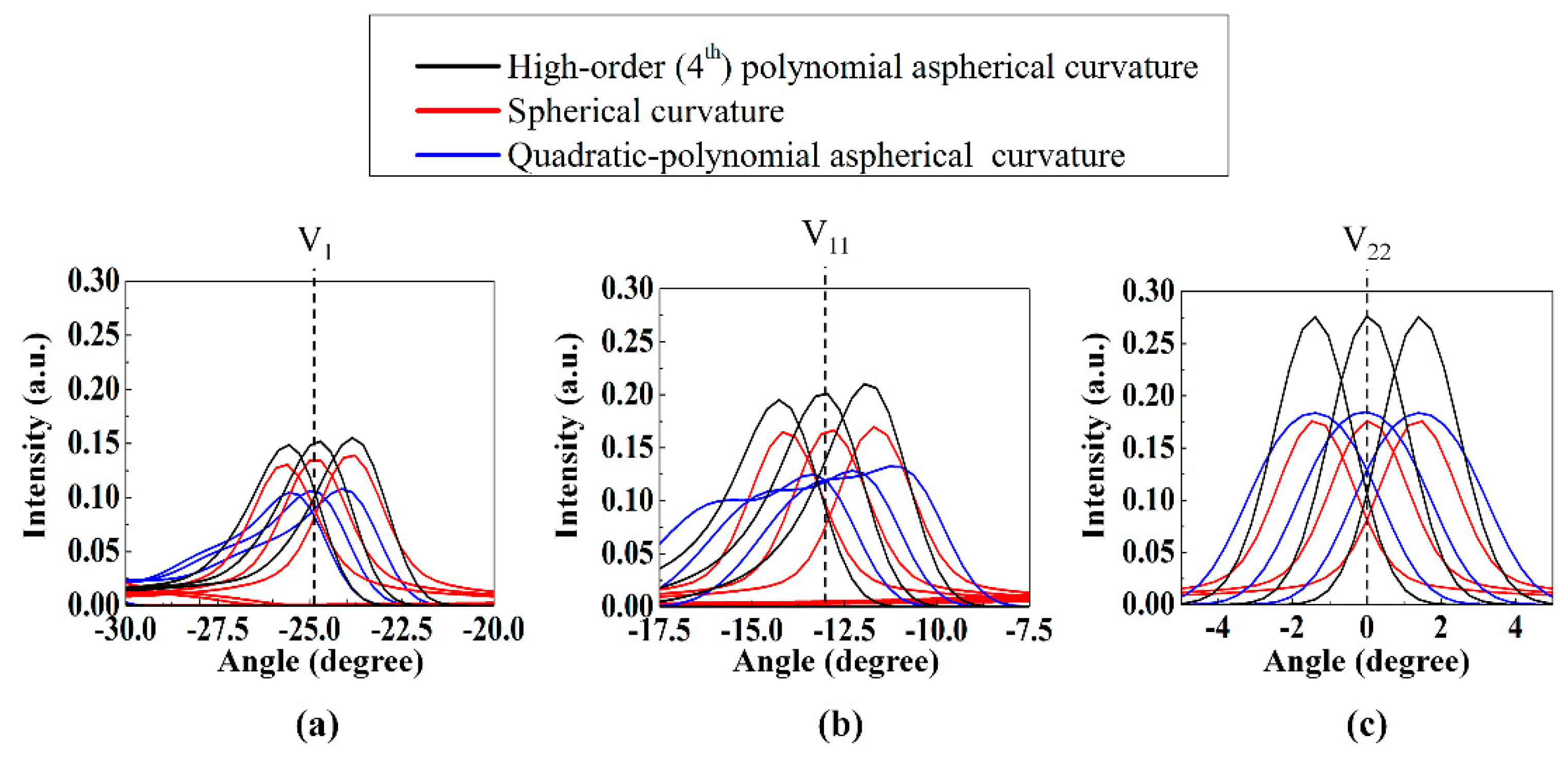
In this study, we designed the interfacial curvature between the plano-convex LC layer and the plano-concave isotropic polymer layer by considering the aberration properties of a small f-number lens. We sectionalized the interfacial curvature into 100 subregions for each elemental lens and used a curvature-fitting procedure to determine the interfacial curvature profile corresponding to the minimum TSA value for the incident rays. We fitted three different curvature functions corresponding to (i) the conventional spherical curvature, (ii) a quadratic polynomial aspherical curvature, and (iii) a high-order (fourth-order) polynomial aspherical curvature. For the different interfacial curvature designs, we analyzed the TSA values for the red, green, and blue wavelengths considering the material dispersion characteristics of real optical materials potentially applicable to the plano-convex birefringent and plano-concave isotropic layers. The TCA properties of the polarization-dependent-switching LC GRIN lens arrays adopting three different interfacial curvatures were also evaluated for comparison.

2.2. Interfacial Curvature Design for LC-Based GRIN Lens with Small F-Number

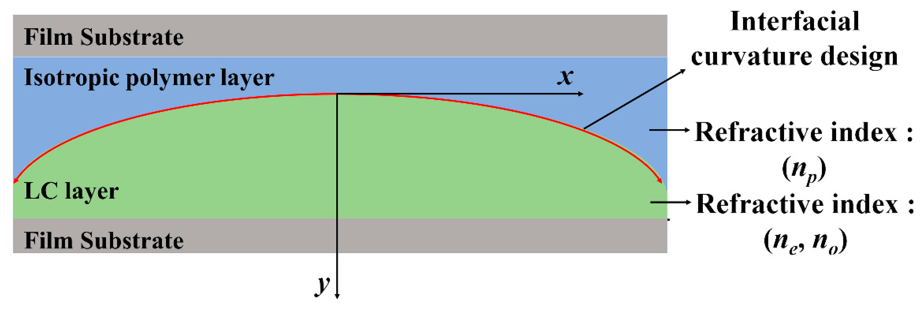
Figure 2 shows a schematic depicting the interfacial curvature between the plano-concave isotropic polymer layer and the plano-convex-shaped birefringent LC layer of the assembled structure of the LC GRIN lens array. The LC molecules need not be electrically reoriented for switching between the defocusing and focusing modes, which corresponds to switching between the 2D and 3D modes, since the defocusing and focusing modes are determined by the incident polarization state, unlike conventional electrically switching LC lenses. Therefore, the lens can maintain an ideal lens profile according to the designed interfacial curvature shape. In conventional LC lenses, however, the LC is directly electrically reoriented to switch between the focusing and defocusing modes, and the reorientation depends on the applied voltage and complex internal electric field distribution. Therefore, a low-viscosity LC is needed to use a low switching voltage while achieving a relatively fast response time. However, low-viscosity LCs have low-∆n property, meaning that it is difficult to obtain a small-f-number lens with a large curvature for the GRIN lens profile determined by the LC geometry. As the structure of polarization-dependent-switching LC GRIN lenses is divided into an LC GRIN lens and the polarization-switching layer, the operating voltage and switching response time are determined by the polarization-dependent-switching layer and not by the LC GRIN lens. Therefore, high-viscosity high-∆n LCs can be used in the presented polarization-dependent-switching LC GRIN lenses. An advantage of using LCs with high-∆n in GRIN lenses is that the refractive index difference at the interface between the isotropic polymer layer and the birefringent LC layer is large, and this decreases in the required thickness of the LC layer in the LC GRIN lens, even for a small-f-number lens. The reduction in the thickness of the lens is very important to obtain an ideal lens profile. In this study, a comparison of two types of polarization-dependent-switching LC GRIN lenses—one with a low-∆n LC and the other with a high-∆n LC—was performed by varying the interfacial curvature profile, which was the simulation parameter. For each type of LC, the curvature profiles were designed according to the xy plane, as shown in Figure 2.
In this study, the ray-tracing-based Advanced System Analysis Program (ASAPTM; Breault Research Organization, Inc.) simulation tool was used to analyze the focusing properties of the LC GRIN lenses with the designed curvatures at λ = 550 nm (green). 
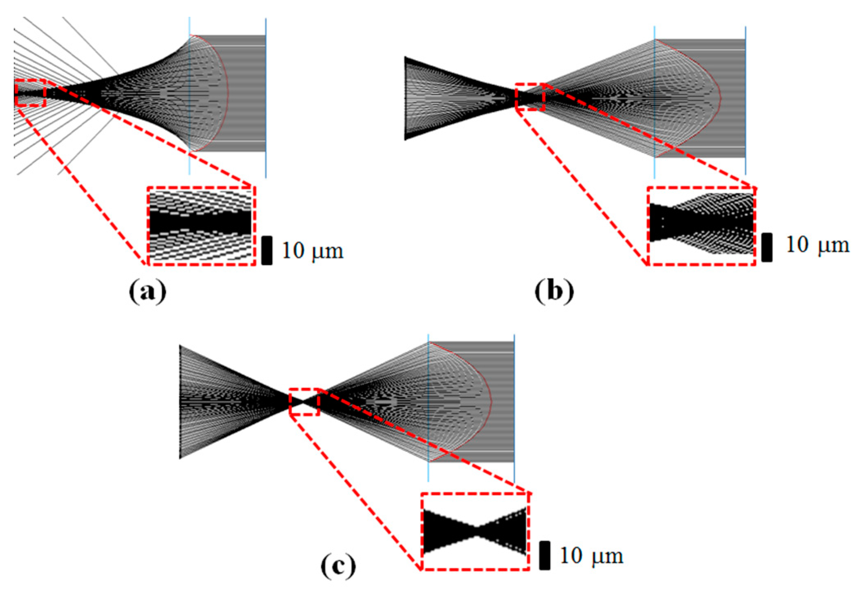
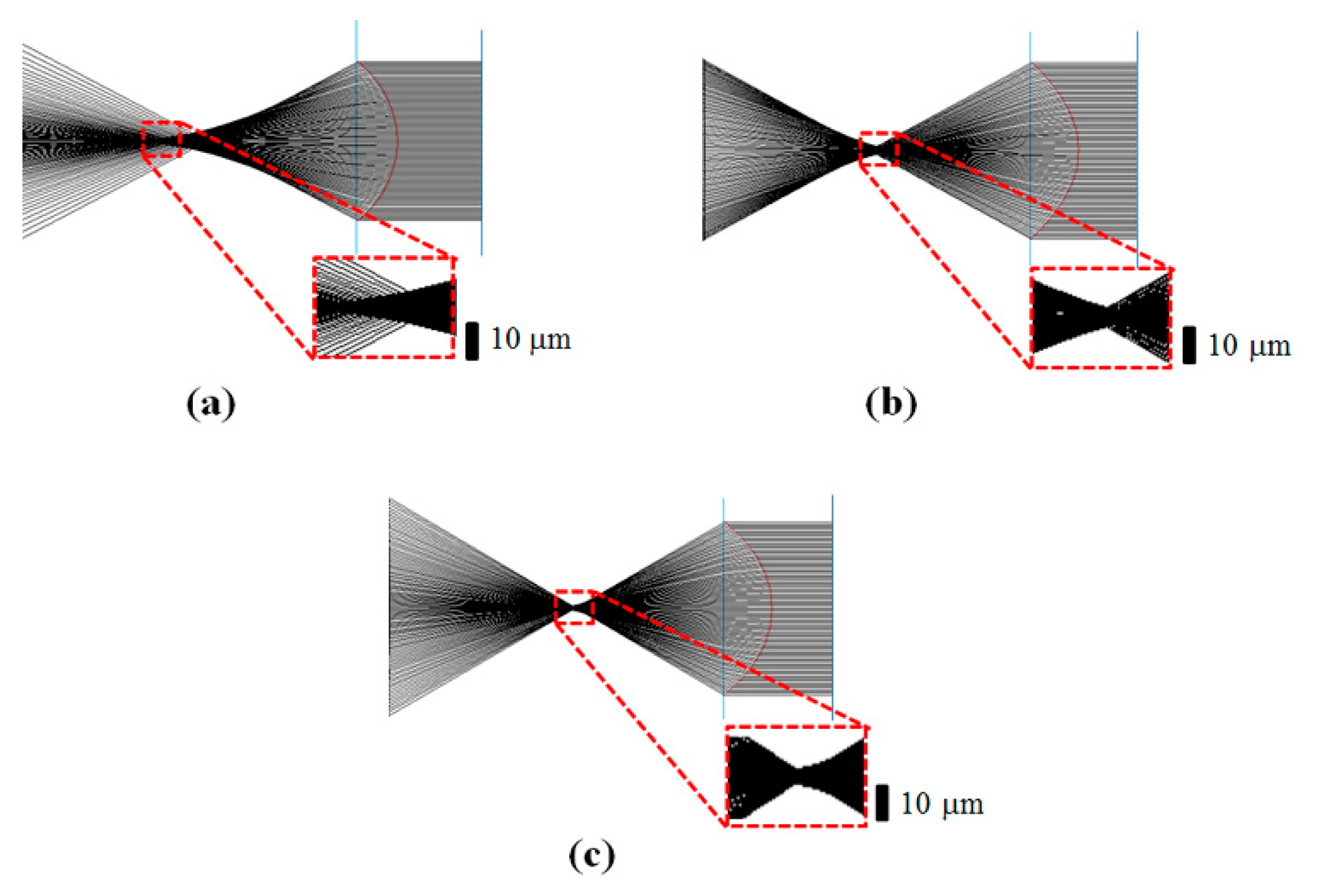
Figure 3 shows the results of the focusing property simulation for the low-∆n LC GRIN lens for different curvature profiles, namely, spherical, quadratic polynomial aspherical, and high-order polynomial aspherical curvature profiles at the single wavelength (λ = 550 nm). In the LC GRIN lens structure, the refractive index of the isotropic polymer (np) was np = 1.51 [32], and the refractive indices of the LC layer (ne, no, ∆n = neno) were ne = 1.69, no = 1.51, and ∆n = 0.18, respectively, at λ = 550 nm [30]. The f-number and elemental lens pitch of the designed GRIN lens were 1.08 and 285 µm, respectively, irrespective of the type of interfacial curvature. We previously reported a polarization-dependent-switching LC GRIN lens with an f-number of 4 for 10-view 3D viewing conditions; an elemental lens pitch of 150 μm, viewing window of 15° and a 5.5 inch mobile panel (2560 × 1440, 538 ppi) were used [30]. In this work, a much smaller f-number lens (f-number = 1.08) was considered for a wider 3D viewing window of 50°. In our previous work where the switchable lens was designed for a 3D viewing window of 15°, the use of the quadratic polynomial aspherical interfacial curvature was sufficient to achieve reduced aberration compared with the aberration for the spherical interfacial curvature. Furthermore, for a lens with an f-number of 1.08, the focusing behavior of the LC GRIN lens with a quadratic polynomial aspherical interfacial curvature was far superior to that with a spherical interfacial curvature, as shown in Figure 3a,b. However, the aberration properties of Figure 3b should be improved further for a lens with a considerably small f-number, which is considered in the present work. Figure 3c shows that the lens aberration can be considerably improved by adopting a high-order polynomial aspherical curvature for the polarization-dependent-switching LC GRIN lens. The obtained TSA values for the LC GRIN lenses with the three types of interfacial curvatures were 1000.5, 80.1, and 15.2 μm for the spherical, quadratic polynomial, and high-order polynomial aspherical curvatures, respectively. For the different types of interfacial curvatures, the optimized curvature functions for minimizing the TSA and the evaluated TSA values are listed in Table 1.
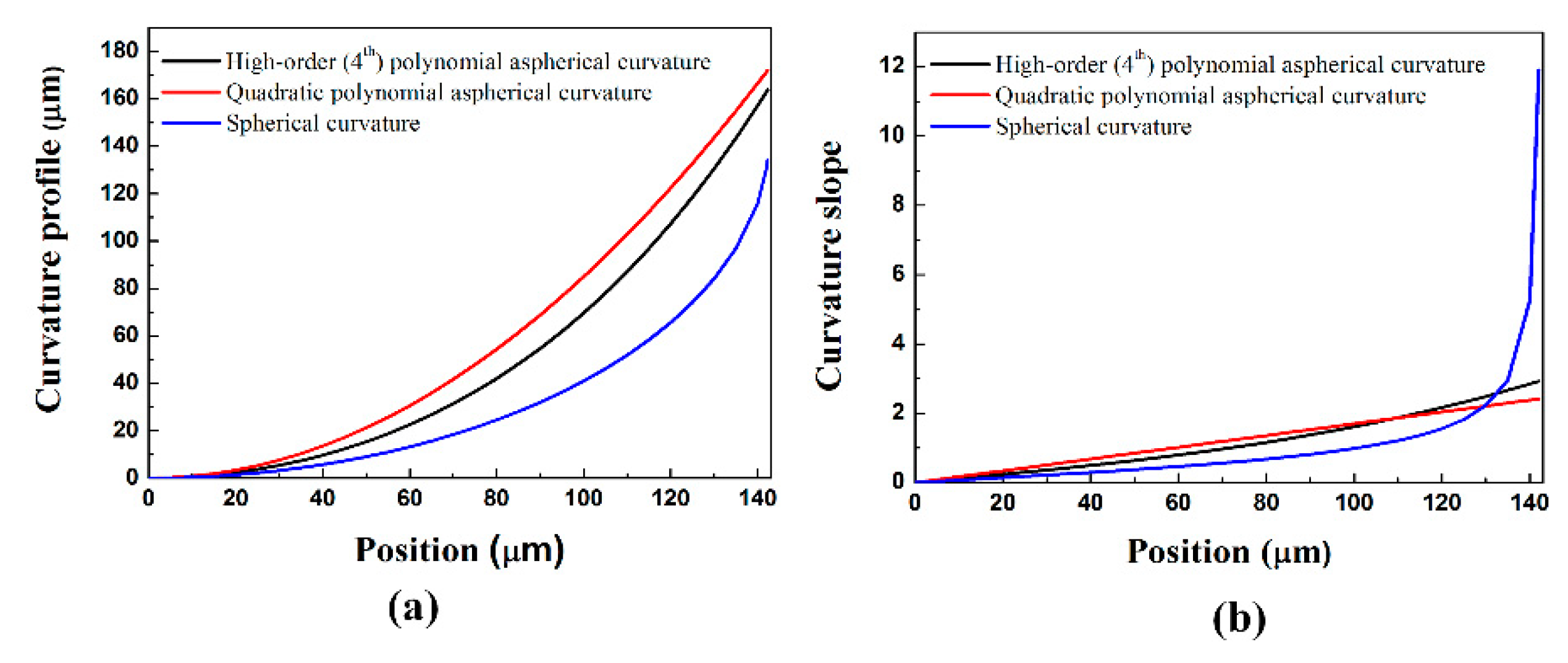
Figure 4a,b show the positional curvature profiles and positional curvature slopes of the low-∆n LC GRIN lens for spherical, quadratic polynomial aspherical, and high-order polynomial aspherical curvatures; the curvature profiles are given by y = 0.1425 0.1425 2 x 2 , y = 8.5 x 2 , and y = 109.7575 x 4 + 5.8695 x 2 , respectively. The x and y values are in millimeters. For the spherical interfacial curvature, the curvature profile function was determined from the elemental lens pitch required for the f-number of the lens. For the quadratic polynomial aspherical and high-order polynomial aspherical curvatures, the curvature functions were derived based on the minimization of the aberration value. According to the curvature profiles in Figure 4a, the lens thickness of the plano-convex LC layer was 142.5, 175, and 165 μm for the spherical, quadratic polynomial aspherical, and high-order polynomial aspherical curvatures, respectively. As shown in Figure 1c, the TSA of the lens can be determined from the difference between the focusing of the marginal ray and paraxial ray. To minimize the difference in focal length for these two rays, the curvature slope around the marginal ray must be reduced, while that around the paraxial ray must be increased. When we compare the positional slope of the spherical curvature with those of the aspherical curvatures in Figure 4b, the curvature slope of the spherical curvature is greater for lens positions around the marginal ray. In addition, the curvature slope for the paraxial ray is the smallest for the spherical curvature. Consequently, the shortest and longest focal lengths are observed for the marginal ray and paraxial ray in the LC GRIN lens with a spherical interfacial curvature, resulting in the lens exhibiting the largest aberration among the three types of lens designs.
In the case of the quadratic polynomial aspherical curvature, the focal length for the marginal ray exceeds that for the paraxial ray, and the focal length difference between them is lower than that for the spherical curvature lens design, as shown in Figure 3b and Figure 4b. However, for our small f-number lens, the relatively large focal length for the marginal rays in the quadratic polynomial aspherical curvature lens prevents further improvement of the aberration properties of the LC GRIN lens although it can be useful for improving the aberration properties of a larger-f-number lens [30]. In the case of the high-order polynomial aspherical curvature, the curvature slope around the marginal ray was larger and that around the paraxial ray was lower compared with the curvature slopes for the quadratic polynomial aspherical curvature, as shown in Figure 3c and Figure 4b. In the case of the high-order polynomial aspherical curvature, the focal length for the marginal ray is shorter than that for the paraxial ray, similar to the case of the spherical interfacial curvature. However, the focal length difference between the paraxial ray and the marginal ray can be effectively reduced in the case of the high-order polynomial aspherical curvature, even for the small f-number (=1.08) of the LC GRIN lens.
As explained before, unlike LC-based electro-optic devices that involve direct field-induced switching of the LC layer, a high-∆n LC can be employed as the plano-convex birefringent layer in a polarization-dependent-switching LC GRIN lens. Ray simulations were performed for the three types of interfacial curvatures by using a high-∆n LC (∆n = 0.4 at λ = 550 nm), and the simulation results are shown in Figure 5. In the high-∆n LC GRIN lens structure, the refractive index of the isotropic polymer was set to be np = 1.51, which was identical to the refractive index of the isotropic polymer used in the low-∆n LC GRIN lens. The refractive indices of the high-∆n LC were assumed to be ne = 1.91 and no = 1.51. The commercially available high-∆n LC LCM-1107 (LC Matter Co.: ne = 1.94, no = 1.54 at λ = 550 nm) has refractive index values similar to those considered in our simulation [33,34]. It has been reported that the high-∆n LCs are not stable under UV exposures in general due to the molecular structures introduced to increase the LC birefringence [33,34]. However, unlike the polarization-dependent-switching GRIN lens arrays using the reactive mesogen (RM) as the plano-convex birefringent layer [30], the polarization-dependent-switching LC GRIN lens arrays do not require the UV exposure process for UV-induced polarization of the RM layer during manufacturing compared with the manufacturing procedures explained in detail in our previous work with the polarization-dependent-switching RM GRIN lens arrays [30]. The f-number and lens pitch of the designed high-∆n LC GRIN lens were 1.08 and 285 µm, respectively, irrespective of the type of interfacial curvature, and these values were identical to those of the low-∆n LC GRIN lens. For the three types of curvature-fitting functions, the optimized curvature profiles for the minimum TSA were derived, as listed in Table 1. For the high-∆n LC, the focusing properties of the three curvatures shown in Figure 5a–c are superior to those for the low-∆n LC shown in Figure 3a–c. The determined TSA values of the LC GRIN lenses with spherical, quadratic polynomial, and high-order polynomial aspherical curvatures were 100.3, 30.4, and 10.2 μm, respectively, which are lower than the TSA values of the low-∆n LC GRIN lens for these curvatures by factors of 10, 2.6, and 1.5, respectively. Similar to the case of the low-∆n LC GRIN lenses, the smallest and largest TSA values of the high-∆n LC GRIN lenses were observed for the high-order polynomial aspherical curvature and spherical curvature, respectively, and the reason for this observation is identical to that presented for Figure 3 and Figure 4.
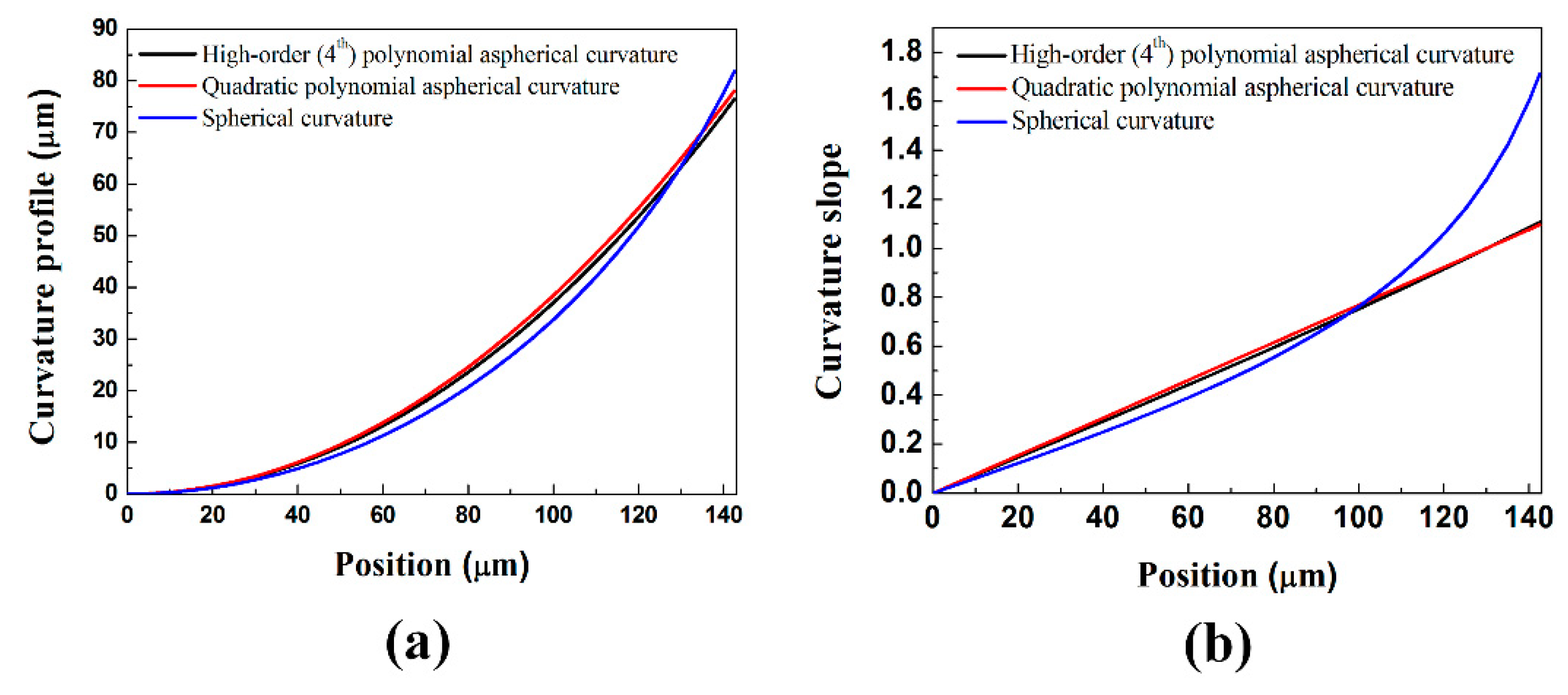
Figure 6a,b show positional curvature profiles and positional curvature slopes for the high-∆n LC GRIN lenses with spherical, quadratic polynomial aspherical, and high-order polynomial aspherical curvatures. The curvature profiles of the designed lenses were y = 0.165 0.165 2 x 2 (spherical curvature), y = 7.689 x 2 (quadratic polynomial aspherical curvature), and y = 23.5 x 4 + 7.289 x 2 (high-order polynomial aspherical curvature). As shown in Figure 6a, the thickness required for the plano-convex LC layer was 85, 75, and 72 μm for the spherical, quadratic polynomial aspherical, and high-order polynomial aspherical profiles, respectively. For all the curvatures, the LC layer thickness required for the high-∆n LC GRIN lens was smaller than that required for the low-∆n LC GRIN lens, which is evident from Table 1. From the practical viewpoint of the manufacturing yield, a considerably small LC layer thickness can facilitate the uniformity of the homogeneously planar LC alignment, although the ideal LC alignment was assumed in our simulation analysis. Importantly, the use of the high-∆n LC for the LC GRIN lens led to the positional curvature slopes for both the marginal ray and paraxial ray being considerably smaller than those for the low-∆n LC GRIN lens with the same f-number (Figure 4b and Figure 6b). Furthermore, the TSA values of the designed curvatures of the high-∆n LC GRIN lens can be further reduced, unlike the case of the low-∆n LC GRIN lens. These results show that an LC material with high-∆n as well as an optimized aspherical curvature design can minimize the TSA of the 2D/3D switchable LC GRIN lens with a small f-number. For the three interfacial curvatures designed for the high-∆n LC GRIN lens arrays, the practically available optical material conditions were applied to the polarization-dependent-switching LC GRIN lens array structures to analyze the aberration effects by the material dispersion characteristics and their wavelength-dependent TSA and TCA properties were evaluated. As the plano-convex high-∆n LC and plano-concave isotropic layers, the material dispersion curves of LCM 1107 and UV-cured NOA81, respectively, were used [32,33,34]. The Cauchy equations used to consider the material dispersion properties in our aberration analysis are
n e   ( λ ) = 1.87500 + 0.00624 ( λ / μ m ) 2 + 0.00402 ( λ / μ m ) 4 ,
n o   ( λ ) = 1.51200 + 0.008962 ( λ / μ m ) 2 + 0.000114 ( λ / μ m ) 4 ,
n p   ( λ ) = 1.46400 + 0.00160 ( λ / μ m ) 2 + 0.00382 ( λ / μ m ) 4 ,
In Equations (1) and (2), ne(λ) and no(λ) are the Cauchy functions of the high-∆n LC of LCM 1107. Equation (3) for 
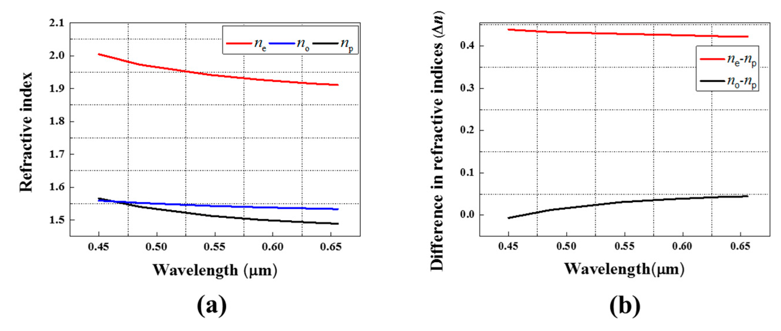
np(λ) is the Cauchy function of NOA81. As shown in Figure 7a, the two Cauchy curves of ne(λ) and np(λ) have similar dispersion characteristics and ne = 1.916 and np = 1.492 for λ = 630 nm (red), ne = 1.940 and np = 1.511 for λ = 550 nm (green), and ne = 2.004 and np = 1.565 for λ = 450 nm (blue). Thus, although the (ne-np) amount becomes slightly increased with decreasing wavelength, the wavelength-dependence of the (nenp) values is negligible, as shown in Figure 7b, exhibiting a small value of maximum deviation of 0.009 at λ = 450 nm from the average amount of <nenp> = 0.430 over the entire visible region. Compared with the dispersion property of the (nenp) value for the 3D mode operation, the dispersion property of the (nonp) value for the 2D mode operation shows a relatively higher wavelength dependency, as shown in Figure 7a,b. However, the average of the (nonp) values over the visible region is 0.0256, exhibiting quite a low level of index mismatching. For achieving a more ideal index-matching condition over the entire visible region, a further material optimization would be needed.
When the material dispersion conditions shown in Figure 7 were applied to the high-∆n LC GRIN lens arrays designed with the three different interfacial curvatures listed in Table 1, the wavelength-dependent TSA values listed in Table 2 show the minimum at λ = 630 nm (red) and the maximum at λ = 450 nm (blue) identically for three types of interfacial curvatures because the interfacial curvatures shown in Table 1 were designed with the assumption that the refractive index condition of nenp = 0.4, which matches better in the red light rather than the blue light in the case of using the commercially available materials of LCM 1107 and NOA81. However, the wavelength-dependent TSA values of Table 2 do not show a meaningful difference between each other over the entire visible range for each interfacial curvature design condition, although the refractive indices of LCM 1107 and NOA81 are highly dependent on the wavelength, as shown in the dispersion curves of Figure 7a. Among the three interfacial curvature designs, the TSA values were the lowest over the whole visible range in the case of using the high-order polynomial aspherical curvature. The variation of the wavelength-dependent TSA values was also the lowest under the high-order polynomial aspherical curvature condition.
Using the material dispersion values, the TCA properties according to the interfacial curvature designs were also characterized, as shown in Figure 8. For the spherical, quadratic polynomial, and high-order polynomial aspherical interfacial curvatures, the TCA values over the visible range were derived as TCA = 13.4 μm, 12.2 μm, and 11.5 μm, respectively, as listed in Table 2. For all cases, the TCA values were lower than the TSA values, indicating that it is more important to reduce the TSA properties by employing the well-designed interfacial curvature in a small f-number lens. It is worthwhile to note that the TSA value of the LC GRIN lens array with the spherical interfacial curvature is quite large but the TCA value is quite small. In the polarization-dependent- switching LC GRIN lens array, the wavelength-dependent TSA and TCA properties are determined by the dispersion characteristics of (nenp) not by the individual dispersion properties of ne(λ) and np(λ). One of the merits of the presented switchable lens type is that the wavelength-dependent aberration effect in the plano-convex lens can be effectively compensated with that in the plano-concave lens by properly choosing the optical materials of the plano-convex and plano-concave lens parts for the (nenp) value to be nearly constant over the visible range. For comparison, the wavelength-dependent ray simulation result for the single-layered plano-convex lens with the spherical curvature at the polymer-air interface is presented in Figure 8a, where the NOA81 was used as the isotropic polymer layer. In Figure 8a, the lens conditions of the lens pitch, the focal length, and the f-number were the same as those of Figure 8b–d. However, the TCA value in Figure 8a was 59.4 μm, which was much higher than the TCA values obtained in three types of the polarization-dependent-switching LC GRIN lens arrays. These results clearly indicate that the presented lens type of the polarization-dependent-switching LC GRIN lens array utilizing the index mismatching condition between two assembled optical layers of the plano-convex and plano-concave lenses is advantageous compared to the single-layered switchable lens types, such as the field-driven LC-switching GRIN lenses [16,17,18,19,20,21,22,23,24], in reducing the TCA properties, especially for a small f-number lens design with a highly-dispersive high-Δn LC.

3. Analysis of 3D Crosstalk Level According to Lens Design

In the previous section, we confirmed that lens aberration properties can be considerably improved by adopting the high-order polynomial aspherical curvature and the high-∆n (∆n = 0.4) LC in the polarization-dependent-switching LC GRIN lens, especially for a small f-number. Since the aberration properties of the high-∆n LC GRIN lenses were superior to those of the low-∆n LC GRIN lenses, irrespective of the curvature profile types, we compared the 3D crosstalk levels for the three types of curvature profiles by employing the high-∆n LC as the plano-convex birefringent layer in the LC GRIN lens. Figure 9a shows a cross-sectional schematic of the polarization-dependent-switching high-∆n LC GRIN lens array assembled on a quad high-definition (QHD; 3120 (H) × 1440 (V); 750.6 ppi) mobile panel for realizing a 2D/3D switchable display in our simulation. The gap between the mobile panel and the polarization-dependent-switching LC GRIN lens array was designed to be 500 μm for a 3D viewing window of 50°, and the elemental lens had an f-number of 1.08. The viewing window condition of 50° designed in our simulation is sufficiently wide for a single mobile viewer to get full-parallax 3D experience and prevents the inverse 3D image formation that occurs by the 2nd-order viewing zone overlapping with the 1st-order viewing zones during horizontal head movements of a viewer [35,36]. For achieving a wider 3D viewing window, the gap between the elemental lens array and the display panel and the f-number of the lens should be smaller. Therefore, thin-film substrates were used in the LC GRIN lens array for both parts (the polarization-dependent LC GRIN lens and polarization-switching LC layer), as shown in Figure 9a.
Figure 9b shows the sub-pixel rearrangement in the super-multi-view (43-view) 2D/3D switchable display operated through the polarization-dependent-switching LC GRIN lens array. Each elemental lens covers 43 sub-pixels for each R/G/B image with 43 views, and the lens array axis was slanted at 9.46° with respect to the direction of pixel arrangement. The slanted configuration of the lens array has the advantages of reducing the color moiré pattern in the autostereoscopic 3D display and providing well-matched horizontal and vertical 3D resolutions by increasing the horizontal resolution instead of decreasing the vertical resolution. In Figure 9b, the LC alignment direction in the LC GRIN lens array is parallel to the slanted lens axis. In this configuration, the 3D resolution at each viewpoint is 440 (H) × 220 (V). The specifications of the multi-view 2D/3D switchable mobile display are listed in Table 3. For the polarization-switching LC layer, which controls the incident polarization state of the polarization-dependent LC GRIN lens, a 90° twisted-nematic (TN) LC mode was considered with the LC alignment direction at the bottom of the TN LC layer being parallel to the slanted lens axis. In our configuration, the transmission axis of the polarizer attached on bottom of the stacked structure of the polarization-dependent-switching LC GRIN lens array and the TN LC layer is also parallel to the slanted lens axis. Like other types of the LC-based switchable lens array, the brightness level is decreased by 50% at the polarizer when the organic light-emitting display is employed as the mobile panel. In the case of using the liquid crystal display (LCD) as the mobile panel, it is appropriate to set the transmission axis of the analyzer on the LCD panel as being parallel to the y-axis in our slated lens axis condition [30]. In the case of using the LCD panels, the loss of the brightness level can be further minimized by inserting a half waveplate between two polarizers. The LC GRIN lens array was operated in the 3D and 2D modes under the field-on and field-off conditions of the polarization-switching TN LC layer, and the 3D crosstalk levels were analyzed for different curvatures. The distribution of rays emitted from each color subpixel was assumed to be Lambertian in the ASAP simulation. For each subpixel, the ray flux density was 10,000 rays/subpixel, and there was no ray flux within the black matrix areas. For the 3D crosstalk evaluation, the angular luminance distribution for each viewpoint was characterized at an angular sampling resolution of 0.16° at the designed viewing distance. The refractive indices of the cover glass layer, sheet polarizer, and film substrates were assumed to be 1.51, 1.61, and 1.61 in the simulation, respectively. The refractive indices of the TN LC were ne = 1.738 and no = 1.515. The layer thicknesses of the TN LC, film substrate, sheet polarizer, and cover glass were 10, 100, 90, and 200 μm, respectively.
Figure 10a–c shows the simulation results for the viewing distribution of the QHD (750.6 ppi) mobile panel operating in the autostereoscopic multi-view (43-view) 3D mode through the polarization-dependent-switching high-∆n LC GRIN lens array with spherical, quadratic polynomial aspherical, and high-order polynomial aspherical curvatures. In this characterization, the viewing distance was 500 mm. As shown in Figure 10, the 3D viewing window for the 43 viewpoints was 50°, and the angle between adjacent views was about 1.22°. To accurately analyze the 3D crosstalk properties associated with the aberration of the LC GRIN lens for the different curvature profiles, we compared the adjacent crosstalk (Ci, %) levels determined from the following equation for each viewpoint of the LC GRIN lens:
C i ( % ) = ( j I i , j ) I i , i j I i , j × 100
where Ii,j is the overlapping intensity of the jth view evaluated at the ith viewpoint. In Figure 10a–c, the adjacent crosstalk (C22 (%)) values evaluated at the normal viewpoint are 65%, 63.4%, and 45.5%, respectively. The angular luminance distribution for the 22nd view of the LC GRIN lens with a high-order polynomial aspherical curvature was considerably sharper than those of the LC GRIN lenses with spherical and quadratic polynomial aspherical curvatures. This observation is also evident from the higher angular peak intensity levels around the normal viewpoints in Figure 10c compared with those in Figure 10a,b. The adjacent crosstalk (C1 (%)) values evaluated at a side viewpoint of the 3D viewing window boundary were 74.6%, 78.99%, and 71.3% for the spherical, quadratic polynomial aspherical, and high-order polynomial aspherical curvatures, respectively. For all the interfacial curvatures, the adjacent-crosstalk level increased when the measurement shifted from the normal view to the side view. In Figure 10a–c, the average values (<Ci (%)>) of the adjacent crosstalk levels are about 68.5%, 73.3%, and 60.0% for the spherical, quadratic polynomial aspherical, and high-order (fourth-order) polynomial aspherical curvatures, respectively. As evident from the evaluation results of C1 and C22, the average adjacent crosstalk value of the LC GRIN lens array with a high-order aspherical curvature was considerably smaller than those of the spherical and quadratic polynomial aspherical curvatures.
Similar to the TSA evaluation results in Table 1, the adjacent crosstalk level for every viewpoint and the average value were the lowest for the high-order aspherical interfacial curvature. However, unlike the case of the TSA values, the average value of the adjacent crosstalk levels was the worst for the quadratic polynomial aspherical curvature. To analyze this point, we present the angular luminance distributions for the different interfacial curvatures in Figure 11; the luminance distribution of the selected view is co-plotted with those of the two adjacent views at the edge of the viewing window (V1 at a viewing angle of − 24.6°), the oblique mid-view (V11 at a viewing angle of − 12.9°) within the viewing window, and the normal view (V22 at a viewing angle of 0°). In the case of the quadratic polynomial aspherical curvature, the angular luminance distributions near V22 (Figure 11c) are sharper than those of the spherical curvature, similar to the TSA evaluation results. However, the broadening of the angular luminance distributions with an increase in the viewpoint angle is greater for the quadratic polynomial aspherical curvature compared with the broadening for the spherical curvature. For the high-order polynomial aspherical interfacial curvature, the sharpness of the angular luminance distributions at each viewpoint was relatively well preserved at all angles in the 3D viewing window of 50°.
A comparison of the angular dependence of the adjacent crosstalk levels (C1 (%) to C43 (%)) at each viewpoint for different interfacial curvature profiles is presented in Figure 12. The angular adjacent crosstalk values of the LC GRIN lenses with spherical, quadratic polynomial aspherical, and high-order polynomial aspherical curvatures are co-plotted. Compared with the LC GRIN lenses with the two aspherical curvatures, the adjacent-crosstalk levels of the LC GRIN lens with a spherical curvature exhibit less angular dependence, except for those at the edges of the 3D viewing window. By contrast, while the adjacent-crosstalk levels for the two aspherical curvatures show the minimum adjacent-crosstalk levels around the normal viewpoint, the adjacent-crosstalk levels increase with the viewing angle, reflecting greater angular dependency than the spherical curvature. In particular, the adjacent crosstalk levels of the quadratic polynomial aspherical curvature are higher than even those of the spherical curvature at viewing angles above 4°. The viewing angle range in which the quadratic polynomial aspherical curvature exhibits better adjacent-crosstalk properties than the spherical curvature is considerably narrow for the small f-number. Note that the LC GRIN lens with a quadratic polynomial aspherical curvature designed for achieving a 3D viewing window of 15° with a lens with an f-number of 4.0 in our previous work exhibited angular luminance distribution superior to that of the spherical curvature along with better 3D crosstalk properties [30]. However, Figure 12 shows that the enhancement effect of the quadratic polynomial aspherical curvature on the adjacent crosstalk levels near the normal view was not effective for the small f-number lens, and the average value of adjacent-crosstalk levels over the entire 3D viewing window was the worst for this curvature among all interfacial curvature types because of the higher angular dependence of the adjacent crosstalk degradation for the aspherical curvature. The angular dependence arises from the angular distributed ray incident on the aspherical curvature lenses undergoing more angular asymmetrical refraction at the curvature boundaries than rays incident on the spherical curvature boundary. However, for the LC GRIN lens with a high-order polynomial aspherical curvature, the adjacent crosstalk levels near the normal view could be more effectively improved compared with the other curvatures for the small f-number lens, as evident from Figure 5, Figure 11 and Figure 12. The lowest value of average adjacent-crosstalk levels was achieved for this lens despite the angular properties of the adjacent crosstalk levels being degraded with an increase in the viewing angle, similar to the case of the quadratic polynomial aspherical curvature. In our previous work [30], we demonstrated the 2D/3D switchable 10-view display exhibiting the average crosstalk level of 46.5% in the viewing window condition of 15° by using the quadratic polynomial aspherical interfacial curvature in the polarization-dependent-switching RM GRIN lens array. However, the results of Figure 12 show that it is essential to adopt the high-order aspherical curvature design as well as to use the high-Δn birefringent materials for providing more natural 3D experiences with an enhanced angular 3D resolution image and an expanded 3D viewing window to a 3D viewer without worsening 3D crosstalk levels.

4. Conclusions

We investigated the aberration properties of the polarization-dependent-switching LC GRIN lens arrays with a small f-number lens; such a lens facilitates a wide 3D viewing window capable of providing sufficient 3D parallax experiences to viewers. By varying the interfacial curvature profiles (conventional spherical, quadratic polynomial aspherical, and high-order (fourth-order) polynomial aspherical curvatures), we investigated the TSA properties of lens arrays and their effects on the 3D crosstalk levels. In particular, when the high-order polynomial aspherical curvature profile was employed between the plano-concave isotropic polymer layer and the plano-convex birefringent LC layer, the TSA properties were considerably improved, and a TSA of 10.2 µm was achieved for a lens with an f-number of 1.08, even in the presence of additional nonlinear refraction at the flat air-substrate interface curvature. For the LC GRIN lens, an examination of the positional curvature slopes for the curvature profiles and different LC materials revealed that the use of the high-∆n LC and the implementation of the high-order polynomial aspherical curvature profile effectively reduced the aberration and 3D crosstalk. In the designed multi-view (43-view) 2D/3D switchable mobile displays (3120 × 1440, 750.6 ppi) containing the polarization-dependent-switching LC GRIN lens arrays with the three types of interfacial curvatures, the average values of the adjacent crosstalk levels within the entire viewing window (50°) were 68.5%, 73.3%, and 60.0% for the spherical, quadratic polynomial aspherical, and high-order polynomial aspherical interfacial curvatures, respectively. We observed that the LC GRIN lens with a high-order polynomial aspherical curvature showed a considerably improved 3D crosstalk level in the wide 3D viewing window of 50°. In a comparison of the angular properties of the adjacent-crosstalk levels of the three curvatures, the LC GRIN lens with a spherical interfacial curvature showed less angular dependence. However, the adoption of the aspherical curvature in the LC GRIN lens required a reduction in the overall 3D crosstalk over the entire 3D viewing window for the considerably small f-number of 1.08. The overall 3D crosstalk was evaluated from the average value of adjacent crosstalk levels. Unlike the case of conventional passive lenses, the aberration properties of the LC GRIN lens inevitably degraded. Our results indicate that 3D crosstalk levels in an LC GRIN lens can be reduced by introducing a higher-order lens curvature and a high-∆n LC. Such a GRIN lens can be beneficially used for designing a switchable LC lens for use in wide 2D/3D switchable displays requiring a wide 3D viewing window, a high 3D image resolution with a high ppi panel, or a high angular 3D resolution such as super-multi-view displays.

Author Contributions

Conceptualization, T.-H.L. and H.-R.K.; Data analysis, T.-H.L. and K.-I.J.; Simulation, T.-H.L.; Writing—original draft preparation, T.-H.L. and H.-R.K.; Writing—review and editing, H.-R.K. All authors have read and agreed to the published version of the manuscript.

Funding

This work was supported by the Technology Innovation Industrial Program funded by the Ministry of Trade, Industry & Energy (MI, Korea) [10052667, Development of high sensitive (<30 mJ/cm2) R/G/B color photo-rewritable 3D holographic materials and 1 fps speed frame switching technology].

Conflicts of Interest

The authors declare no conflict of interest.

References

  1. Im, H.; Jung, S.; Lee, B.; Hong, H.; Shin, H. Mobile 3D Displays Based on a LTPS 2.4” VGA LCD Panel Attached with Lenticular Lens Sheets. SID Symp. Dig. Tech. Pap. 2008, 39, 256–259. [Google Scholar] [CrossRef]
  2. Hong, H.-K.; Park, J.; Lee, S.-C.; Shin, H.H. Autostereoscopic multi-view 3D display with pivot function, using the image display of the square subpixel structure. Displays 2008, 29, 512–520. [Google Scholar] [CrossRef]
  3. Dodgson, N.A. Autostereoscopic 3D displays. IEEE Comput Soc. 2005, 38, 31–36. [Google Scholar] [CrossRef]
  4. Willemsen, O.H.; de Zwart, S.T.; Hiddink, M.G.H.; de Boer, D.K.G.; Krijn, M.P.C.M. Multi-view 3D Displays. SID Symp. Dig. Tech. Pap. 2007, 38, 1154–1157. [Google Scholar] [CrossRef]
  5. Park, M.C.; Park, S.J.; Son, J.Y. Stereoscopic imaging and display for a 3-D mobile phone. Appl. Opt. 2009, 48, 238–243. [Google Scholar] [CrossRef] [PubMed]
  6. Takaki, Y. Multi-view 3-D display employing a flat-panel display with slanted pixel arrangement. J. Soc. Inf. Disp. 2010, 18, 476–482. [Google Scholar] [CrossRef]
  7. Lambooij, M.; Hinnen, K.; Varekamp, C. Emulating autostereoscopic lenticular designs. J. Disp. Technol. 2012, 8, 283–290. [Google Scholar] [CrossRef]
  8. Chuang, S.-C.; Chen, C.-H.; Mphepö, W.; Wu, C.-L.; Huang, Y.-P.; Shieh, H.-P.D.; Hsu, S.-C.; Lin, C.-H.; Hu, C.-J. Liquid Crystal Panel for High Efficiency Autostereoscopic 3D Displays. Appl. Opt. 2008, 39, 3446–3454. [Google Scholar] [CrossRef]
  9. Huang, H.; Hua, H. Systematic characterization and optimization of 3D light field displays. Opt. Express 2017, 25, 18508–18525. [Google Scholar] [CrossRef] [Green Version]
  10. Kramida, G. Resolving the vergence-accommodation conflict in head-mounted displays. IEEE Trans. Vis. Comput. Graph. 2016, 22, 1912–1931. [Google Scholar] [CrossRef]
  11. Song, H.; Seo, W.; An, J.; Seo, J.; Sung, G.; Choi, C.-S.; Kim, S.; Kim, H.; Kim, Y.; Kim, Y.-T. Super Multi-View 3D Display with Reduced Accommodation-Vergence Conflict using the Holographic Method. SID Symp. Dig. Tech. Pap. 2016, 47, 994–997. [Google Scholar] [CrossRef]
  12. Honda, T.; Kajiki, Y.; Susami, K.; Hamaguchi, T.; Endo, T.; Hatada, T.; Fujii, T. Three-dimensional display technologies satisfying “super multiview condition”. Proc. SPIE 2001, 10298, 102980B1–102980B32. [Google Scholar]
  13. Woodgate, G.J.; Harrold, J. Efficiency analysis for multi-view spatially multiplexed autostereoscopic 2-D/3-D displays. J. Soc. Inf. Disp. 2007, 15, 873–881. [Google Scholar] [CrossRef]
  14. Willemsen, O.H.; de Zwart, S.T.; Hiddink, M.G.H.; Willemsen, O. 2D/3D Switchable Displays. J. Soc. Inf. Disp. 1997, 10, 1–5. [Google Scholar]
  15. Lee, B.; Park, J.-H. Overview of 3D/2D switchable liquid crystal display technologies. Proc. SPIE 2010, 7618, 1–10. [Google Scholar]
  16. Hassanfiroozi, A.; Huang, Y.-P.; Javidi, B.; Shieh, H.-P.D. Hexagonal liquid crystal lens array for 3D endoscopy. Opt. Express 2015, 23, 971–981. [Google Scholar] [CrossRef]
  17. Ye, M.; Wang, B.; Kawamura, M.; Sato, S. Image formation using liquid crystal lens. Jpn. J. Appl. Phys. 2007, 46, 6776–6777. [Google Scholar] [CrossRef]
  18. Ye, M.; Wang, B.; Sato, S. Realization of liquid crystal lens of large aperture and low driving voltages using thin layer of weakly conductive material. Opt. Express 2008, 16, 4302–4308. [Google Scholar] [CrossRef]
  19. Lin, Y.H.; Chen, H.S.; Lin, H.C.; Tsou, Y.S.; Hsu, H.K.; Li, W.Y. Polarizer-free and fast response microlens arrays using polymer-stabilized blue phase liquid crystals. Appl. Phys. Lett. 2010, 96, 1–4. [Google Scholar] [CrossRef] [Green Version]
  20. Li, Y.; Wu, S.-T. Polarization independent adaptive microlens with a blue-phase liquid crystal. Opt. Express 2011, 19, 8045–8050. [Google Scholar] [CrossRef]
  21. Kim, H.; Kim, J.; Kim, J.; Lee, B.; Lee, S.D. Liquid crystal-based lenticular lens array with laterally shifting capability of the focusing effect for autostereoscopic displays. Opt. Commun. 2015, 357, 52–57. [Google Scholar] [CrossRef]
  22. Fan, Y.H.; Ren, H.; Liang, X.; Wang, H.; Wu, S.T. Liquid crystal microlens arrays with switchable positive and negative focal lengths. J. Disp. Technol. 2005, 1, 151–155. [Google Scholar] [CrossRef]
  23. Ren, H.; Fan, Y.H.; Gauza, S.; Wu, S.T. Tunable-focus flat liquid crystal spherical lens. Appl. Phys. Lett. 2004, 84, 4789–4791. [Google Scholar] [CrossRef]
  24. Lee, C.-T.; Li, Y.; Lin, H.-Y.; Wu, S.T. Design of polarization-insensitive multi-electrode GRIN lens with a blue-phase liquid crystal. Opt. Express 2011, 19, 17402–17407. [Google Scholar] [CrossRef]
  25. Chen, H.-S.; Lin, Y.-H.; Srivastava, A.K.; Chigrinov, V.G.; Chang, C.-M.; Wang, Y.-J. A large bistable negative lens by integrating a polarization switch with a passively anisotropic focusing element. Opt. Express 2014, 22, 13138–13143. [Google Scholar] [CrossRef]
  26. Zhu, R.; Xu, S.; Hong, Q.; Wu, S.; Lee, C.; Yang, C.; Lo, C.; Lien, A. Poly-lens-embedded 2D/3D switchable display with dramatically reduced crosstalk. Appl. Opt. 2014, 53, 1388–1395. [Google Scholar] [CrossRef] [Green Version]
  27. Son, K.-B.; Kim, M.; Park, M.-K.; Kim, H.-R. Polarization-dependent microlens array using reactive mesogen aligned by top-down nanogrooves for switchable three-dimensional applications. J. Opt. Soc. Korea 2015, 19, 265–271. [Google Scholar] [CrossRef] [Green Version]
  28. Woodgate, G.J.; Harrold, J. High Efficiency Reconfigurable 2D/3D Autostereoscopic Display. SID Symp. Dig. Tech. Pap. 2003, 34, 394–397. [Google Scholar] [CrossRef]
  29. Choi, Y.; Kim, H.-R.; Lee, K.-H.; Lee, Y.-M.; Kim, J.-H. A liquid crystalline polymer microlens array with tunable focal intensity by the polarization control of a liquid crystal layer. Appl. Phys. Lett. 2007, 91, 1–3. [Google Scholar] [CrossRef] [Green Version]
  30. Park, M.-K.; Park, H.; Joo, K.-I.; Lee, T.-H.; Kim, H.-R. Polarization-dependent liquid crystalline polymeric lens array with aberration-improved aspherical curvature for low 3D crosstalk in 2D/3D switchable mobile multi-view display. Opt. Express 2018, 26, 20281–20297. [Google Scholar] [CrossRef]
  31. Fang, Y.C.; Liu, T.K.; Wu, B.W.; Chou, J.H.; MacDonald, J. Chromatic aberration elimination for digital rear projection television L-type lens by genetic algorithms. Opt. Lasers Eng. 2008, 46, 363–372. [Google Scholar] [CrossRef]
  32. Park, M.-K.; Park, H.; Joo, K.-I.; Lee, T.-H.; Kwon, K.-C.; Erdenebat, M.-U.; Lim, Y.-T.; Kim, N.; Kim, H.-R. Fast-switching laterally virtual-moving microlens array for enhancing spatial resolution in light-field imaging system without degradation of angular sampling resolution. Sci. Rep. 2019, 9, 1–14. [Google Scholar] [CrossRef] [PubMed] [Green Version]
  33. Gauza, S.; Li, J.; Wu, S.T.; Spadło, A.; Dabrowski, R.; Tzeng, Y.N.; Cheng, K.-L. High birefringence and high resistivity isothiocyanate-based nematic liquid crystal mixtures. Liq. Cryst. 2005, 32, 1077–1085. [Google Scholar] [CrossRef]
  34. Gauza, S.; Wang, H.; Wen, C.H.; Wu, S.T.; Seed, A.J.; Dabrowski, R. High birefringence isothiocyanato-tolane liquid crystals. Jpn. J. Appl. Phys. 2003, 42, 3463–3466. [Google Scholar] [CrossRef] [Green Version]
  35. Lee, S.; Park, J.; Heo, J.; Kang, B.; Kang, D.; Hwang, H.; Lee, J.; Choi, Y.; Choi, K.; Nam, D. Autostereoscopic 3D display using directional subpixel rendering. Opt. Express 2018, 26, 20233–20244. [Google Scholar] [CrossRef]
  36. Kim, S.-K.; Yoon, K.-H.; Yoon, S.-K.; Ju, H. Defragmented image based autostereoscopic 3D displays with dynamic eye tracking. Opt. Commun. 2015, 357, 185–192. [Google Scholar] [CrossRef] [Green Version]
Figure 1. Structure and operating principle of the polarization-dependent-switching liquid crystal (LC)-based gradient refractive index (GRIN) lens array operated through the underlying polarization-switching layer: (a) field-off state and (b) field-on state of the polarization switching twisted nematic LC layer. (c) Aberrations induced by additional refraction between the air and the flat substrate interface. (d) Transverse chromatic aberration induced by the material dispersion.
Crystals 10 00418 g001
Figure 2. Schematic of the interfacial curvature design between the plano-concave isotropic polymer layer and the plano-convex birefringent LC layer in an LC-based GRIN lens array.
Crystals 10 00418 g002
Figure 3. Simulation results for ray distributions for the low-∆n LC GRIN lens array with different interfacial curvatures: (a) spherical, (b) quadratic polynomial aspherical, and (c) high-order (fourth-order) polynomial aspherical curvatures.
Crystals 10 00418 g003
Figure 4. (a) Positional curvature profiles and (b) positional curvature slopes for the low-∆n LC GRIN lens arrays with spherical, quadratic polynomial aspherical, and high-order (fourth-order) polynomial aspherical curvatures.
Crystals 10 00418 g004
Figure 5. Simulation results for ray distributions for the high-∆n LC GRIN lens arrays with (a) spherical, (b) quadratic polynomial aspherical, and (c) high-order polynomial aspherical interfacial curvatures.
Crystals 10 00418 g005
Figure 6. (a) Positional curvature profiles and (b) positional curvature slopes for the high-∆n LC GRIN lens arrays with spherical, quadratic polynomial aspherical, and high-order (fourth-order) polynomial aspherical curvatures.
Crystals 10 00418 g006
Figure 7. (a) Dispersion curves of (a) high-∆n LC of LCM 1107 and isotropic polymer of NOA81 and (b) (nenp) and (nonp) values.
Crystals 10 00418 g007
Figure 8. (a) Simulation results for TCA analysis with the wavelength-dependent ray distributions for the plano-convex microlens array with the lens-curvature air interface, where the isotropic polymer of NOA81 was assumed as the optical material of the lens layer. (bd) Simulation results for TCA analysis with wavelength-dependent ray distributions for the high-Δn LC GRIN lens array with different interfacial curvatures, where LCM 1107 and NOA81 were assumed as the plano-convex birefringent and plano-concave isotropic layers, respectively: (b) spherical, (c) quadratic polynomial aspherical, and (d) high-order (fourth-order) polynomial aspherical curvatures. The red, green, and blue lines present the ray distributions of λ = 630, 550, and 450 nm wavelength, respectively.
Crystals 10 00418 g008
Figure 9. (a) Cross-sectional schematic of the polarization-dependent-switching high-∆n LC GRIN lens array assembled on the quad high-definition (QHD) (750.6 ppi) mobile panel for realizing a 2D/3D switchable display. (b) Subpixel rearrangement for the 43-view autostereoscopic 3D display operating through the polarization-dependent-switching LC GRIN lens array.
Crystals 10 00418 g009
Figure 10. Simulation results showing the viewing distribution of the QHD (750.6 ppi) mobile panel in the autostereoscopic multi-view (43-view) 3D mode by the polarization-dependent-switching high-∆n LC GRIN lens array with (a) spherical, (b) quadratic polynomial aspherical, and (c) high-order (fourth-order) polynomial aspherical curvatures. (d) View-numbering in (ac).
Crystals 10 00418 g010
Figure 11. Angular luminance distributions for different interfacial curvatures. The luminance distribution for the selected view is co-plotted with those of two adjacent views. The selected views are (a) the viewing window edge (V1 at −24.6°), (b) oblique mid-view (V11 at − 12.9°) within the viewing window, and (c) normal view (V22 at 0°).
Crystals 10 00418 g011
Figure 12. Angular dependence of the adjacent crosstalk level of the autostereoscopic multi-view (43-view) displays (750.6 ppi, QHD panel) comprising polarization-switchable high-∆n LC GRIN lens arrays with different interfacial curvatures.
Crystals 10 00418 g012
Table 1. Design parameters of LC GRIN lens arrays and TSA properties.
F-NumberInterfacial Curvature Typen
(λ = 550 nm)
Interfacial Curvature Profile (mm)LC Layer ThicknessTSA Value
1.08
(for viewing window of 50°)
Spherical0.18 y = 0.1425 0.1425 2 x 2 142.5 μm1000.5 μm
0.4 y = 0.165 0.165 2 x 2 85.0 μm100.3 μm
Quadratic polynomial aspherical 0.18 y = 8.5 x 2 175 μm80.1 μm
0.4 y = 7.689 x 2 75 μm30.4 μm
High-order (fourth-order) polynomial
aspherical
0.18 y = 109.7575 x 4 + 5.8695 x 2 165 μm15.2 μm
0.4 y = 23.5 x 4 + 7.289 x 2 72 μm10.2 μm
Table 2. Wavelength-dependent TSA and TCA properties of LC-GRIN lens arrays in case of using LCM 1107 as the plano-convex birefringent layer and NOA81 as the plano-convex isotropic layer.
Interfacial Curvature TypeTSA ValuesTCA Value
Red
(630 nm)
Green
(550 nm)
Blue
(450 nm)
Spherical111.9 μm112.9 μm113.5 μm13.4 μm
Quadratic polynomial aspherical 36.9 μm37.4 μm38.9 μm12.2 μm
High-order (fourth-order) polynomial
aspherical
13.4 μm13.8 μm14.1 μm11.5 μm
Table 3. Specifications of the multi-view 2D/3D switchable mobile display for LC GRIN lenses with different interfacial curvatures.
ItemValue
Mobile display panel2D resolution3120 (H) × 1440 (V)
Size4.5 inch
Pixel pitch33.84 μm (H) × 33.84 μm (V)
Subpixel pitch11.28 μm (H) × 33.84 μm (V)
Effective area of each subpixel,
except black matrix area
8.28 μm (H) × 24.84 μm (V)
Pixel density750.6 ppi
Polarization-dependent-switching LC lens array n0.4
Elemental lens pitch285 μm
Curvature profile (mm)Spherical y = 0.165 0.165 2 x 2
Quadratic polynomial aspherical y = 7.689 x 2
High-order (fourth-order) polynomial aspherical y = 23.5 x 4 + 7.289 x 2
F-number1.08
Slanted angle of lens array9.46°
Multi-view 3D mode operation of the 2D/3D switchable mobile display 3D resolution440 (H) × 240 (V)
Number of views43
Viewing distance500 mm
Viewing window50°
Average value of adjacent crosstalk levelsSpherical curvature68.5%
Quadratic polynomial aspherical curvature73.34%
High-order (fourth-order)
polynomial aspherical curvature
60%

