Abstract
This study investigates nanostrips in Co/Cu/Py spin valve structures by connecting one side to domain wall reservoirs of different shapes in order to manipulate the switching field. The switching field increases according to the injection geometry; a diamond-shape reservior generates the largest switching field, followed by square-shape and then tip shape reservoirs. Simulation indicated the same results, showing that the vortex domain walls nucleated at the junction, but the pinning force increased as the magnetic transition area became larger (the injection angle became smaller). Therefore, by controlling the domain wall injection angles, the switching fields of the nanostrips can be manipulated.
1. Introduction
The manipulation of magnetization reversal processes in various submicron or nanometer configurations is important for future applications in spin electronic devices or ultrahigh density recording media. Recently, the domain wall (DW) has been widely studied in novel magnetic devices, especially racetrack memory [1,2] or spinwave (SW) propagation, has become a significant study area [3,4,5,6]. Magnetization reversal by an electric current is essential for future magnetic data storage technology, such as spin–orbit torque (SOT) magnetic random-access memories (MRAM). It has also been demonstrated that a switching field and magnetization reversal can be manipulated by the motion of domain walls of different geometric shapes [7,8,9,10]. In previous studies, researchers used a nanostrip, with or without square pad structures, to measure the resistance under an external magnetic field. In the nanostrip with a pad sample, they also observed the angular dependence of the switching field Hs of the Co layer at room temperature [11]. The pad possessed a lower coercivity than the nanostrip due to the high anisotropy of the latter, and changes in the magnetization distribution of the pad resulted in the creation of a wall in the vicinity of the pad/nanostrip junction. DW is nucleated at smaller fields in the nucleation elliptical pad, whereas much larger fields are required for DWs to be injected into the nanostrip itself [12]. Fabricated elliptical pads are used to obtain vortex domain walls and investigate the domain wall injection process. According to these studies, variations in pad geometry create distinct domain wall injection modes (angle, position, and wall type), thus affecting the magnetic reversal process [13,14]. The magnetization of the sample could be magnetic- or current-driven so as to change its magnetic state. In other words, the current-driven density is closely related to the switching field. If we can use these reservoirs to reduce the switching field, the energy cost to modify sample magnetization could be reduced. We report the ability of domain wall injection into the nanostrip. In this study, we investigate the influence of reservoirs of different shapes on the domain magnetization reversal process. Domain wall injection behavior is varied in the junction position according to the geometry of the reservoir.
2. Materials and Methods
Patterned nanostrips of different geometries were fabricated using electron-beam lithography and the lift-off process. Using direct current (DC) magnetron sputtering, with a base pressure of 5 × 10⁻⁷ Torr and a working pressure of 1 × 10⁻³ Torr, the samples were deposited onto 50 nm SiO2-coated silicon (100) substrates. The electrical contact leads (Cu/Au) were made in a second step using a similar lift-off process. The width of the leads was 500 nm and the thickness was 80 nm/10 nm. Before the Cu/Au deposition, Ar ion-milling was performed to clean the surfaces of the samples. We fabricated three different reservoirs on one side of the nanostrip, with diamond, square, and tip geometries. The other side of the nanostrip was a tip shape.
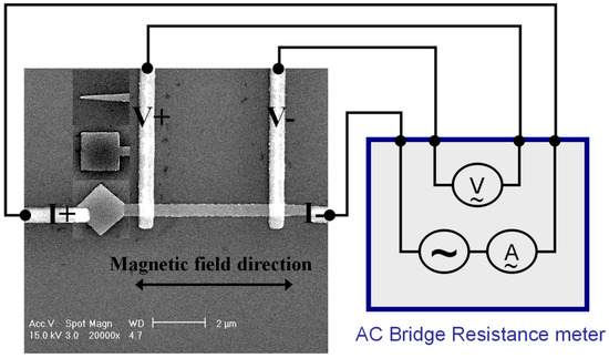
Figure 1 shows a scanning electron microscopy (SEM) photograph of these nanostrips. The line width of the pattern is 0.4 µm and the distance between the two voltage leads is 5 µm. The trilayer spin valve structure is Co (20 nm)/Cu (7 nm)/Py (20 nm). The spin valve structure was used to study the magnetization reversal behavior, because the signal of the giant magnetoresistance (GMR) is much clearer in comparison to the anisotropy magnetoresistance (MR) in a single film. MR was measured at room temperature using a four-probe alternating current (AC) lock-in measurement system under the maximum applied field of 4 kOe. Four terminals—two to pass the current through the sample and two to sense the voltage—were utilized. A Gauss meter in the MR measurement system was used in order to determine the switching field. Because a switching field is a thermally activated process, it has a static distribution. Thus, we made at least ~30 measurements to average the switching field. The error in the magnetic field variation was within ± 1 Oe. The source currents were applied up to 5–20 mA with a step of 10 μA, by pulsing, and the duration was 30 ms. Specifically, each single pulse was applied from the 10 μA measuring current and was followed by the same acquisition current of 10 μA, which was small so as to avoid any joule heating and magnetization activation [15,16]. We also used the micromagnet simulation software OOMMF [17], to simulate the spin configurations of all the samples.

Figure 1.
An SEM image of three shapes with I/V contacts. The images on the left side show the varied reservoir and the nanostrips. From top to bottom are the tip, square, and diamond structures.
3. Results and Discussion
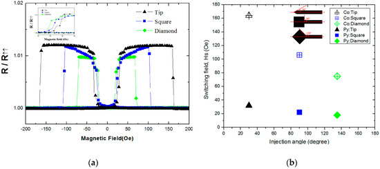
Figure 2a shows typical longitudinal MR curves of these samples. The magnetization reversal process is revealed by the GMR effect. Before measurement, a magnetic field of 4 kOe was applied to align the magnetizations in one direction. In a saturation state, the magnetic moment orientations of the permalloy (Py) and cobalt (Co) layers were aligned in a parallel state, corresponding to the smallest resistance state. Because Py is a soft layer, and Co is a hard layer, when the external magnetic field is gradually decreased from a saturation field and reversed, Py switches its magnetic direction first, and the magnetization transitions into an antiparallel state, with a larger resistance. While there are no data using Kerr microscopy to show how the magnetization reversal occurs, we can define the magnetic field at which the resistance value abruptly increases as the switching field (Hs) of Py.

Figure 2.
(a) Typical longitudinal MR loops of the nanostrips measured at room temperature. The inset illustrates the small magnetic field region. (b) The switching fields of Co and Py versus the domain wall injection angle. The inset illustrates the definition of the injection angle.
Table 1 shows the results of Hs for the three shapes of reservoirs (the error in the magnetic field was ± 1 Oe). Among the three shapes, attaching a tip shape to the nanostrip caused a maximum value of the Hs in the Py layer, and this shows that the anisotropic field with the tip shape was the largest, thus impeding domain wall nucleation. When the magnetic field reaches the switching magnetic field (>32 Oe), the magnetization of the DW at the tip will move quickly across the nanostrip, showing a progressive increase. This behavior is a consequence of the narrow area tip, favoring DW nucleation and DW rotation in the tip structure. On the other hand, the domain wall nucleated easily in the diamond-shaped junction. The diamond, square, and tip shapes allowed for direct switching, indicating that the domain wall moved quickly through the nanostrips and caused the change to occur easily. We then focused on the Co layers, in which the Hs was larger than that in the Py layers. This can be explained by the fact that Co has a larger anisotropy energy and a smaller magnetic domain structure. For both Co and Py, the easiest and most difficult shapes for magnetization reversal were the diamond and tip shapes, respectively. The diamond shape had the minimum width plateau; in other words, it allowed the nanostrips to switch easily, regardless of the kind of magnetic material used (permalloy or cobalt).

Table 1.
The average switching field for the three different geometries.
Figure 2b shows the switching field as a function of the domain wall injection angle. The definition of the injection angle is shown in the inset of Figure 2b. The injection angles of the diamond, square and tip shapes were 135°, 90°, and 30°, respectively. The smaller injection angles tended to require larger switching fields for both magnetic materials. The Hs of these two magnetic materials (Co and Py) in the diamond, square and tip shapes was linear, depending on the injection angle.
According to the experimental data for both Co and Py, the diamond structure had a smaller Hs, and the tip shape had the largest value. For the diamond shape, the magnetic field direction was close to the easy axis, so the domain wall in the diamond nucleated more easily than the square shape. The experimental results of Co and Py exhibited similar tendencies.
The slope of Py was approximately −0.13, and that of Co was near −0.86. The absolute value of the slope for Co was much larger than that for Py.
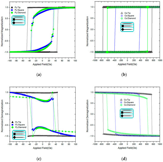
In order to interpret the difference in Hs in relation to magnetization reversal, the spin configurations were simulated using the micromagnet simulation software OOMMF. The simulations were based on the integration of the Landau–Lifshitz–Gilbert equation. The magnetic material Py and Co parameters used for the simulations had a saturation magnetization Ms = 8.0 × 10⁵ A/m(Py) and Ms = 1.4 × 10⁶ A/m(Co) and an exchange stiffness constant A = 1.3 × 10⁻¹¹ J/m(Py) and A = 3.0 × 10⁻¹¹ J/m(Co). The cell size was 5.0 nm in permalloy and 3.0 nm in cobalt, while the damping coefficients α was equal to 0.1. Figure 3a,b shows the hysteresis loops of the simulation results for the different shapes of the reservoir. The insets show the simulated structure. This figure shows more information about the switching behavior. In the case of the tip reservoir, the shape of the hysteresis loop is rectangular. In other structures, it appears that there is a slow decrease in the beginning and a sudden decrease in the next process. The first reason for the gradual drop of the hysteresis loop is the process of DW nucleation and the rotation of magnetization. The second is the small difference in angle between the external field and the DW moving direction. We can infer that the interaction between the domain wall nucleation and magnetic field direction plays an important role in magnetic reversal. Figure 3c,d shows the demagnetization loops of the simulation results in the dissimilar reservoirs in different magnetic fields. The demagnetizing field and applied field describe how the materials’ magnetic field strengths vary with respect to an internal field [18,19].

Figure 3.
(a) The hysteresis loops of permalloy (b) the hysteresis loops of cobalt (c) the demagnetization loops of permalloy (d) the demagnetization loops of cobalt from the OOMMF micromagnetic simulations, which are shown for all of the shapes.
The reason why the hysteresis loop is different for the tip and square/diamond reservoirs is the different magnetization switching mechanisms: for the tip reservoir, the switching mechanism is the nucleation-domain type; for the square/diamond reservoir, the switching mechanism is the static-domain type. For the nucleation domain, the domain wall moves without stopping through the whole magnetic wire. As a result, the tip reservoir hysteresis loop is rectangular and the switching field is higher, and the energy of the domain wall is higher. The domain wall therefore does not stop inside of the wire, and the mechanism is the nucleation domain. For the static domain, the domain wall is stopped in the middle of the wire. It moves gradually as the external magnetic field increases. As a result, the total magnetization of the square/diamond reservoir of the wire changes gradually with the magnetic field [20].
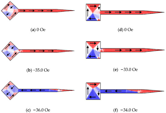
There are two main reasons for the change of Hs. The first is the time that the DW takes to form at the junction, which is related to the DW reservoir shapes. The second is the difference in the DW depinning ability, which is correlated with the DW injection angle (the contact area). Changing the injection angles of the reservoirs caused the Hs variation. In other words, the depinning (Zeeman) energy of the DW was also altered, and this energy was directly proportional to the external magnetic field. From these results we gain key information. Specifically, the vortex DW injection angle influences the switching behavior. From the simulation results of Py, we can observe that each reservoir has a similar transition state. As shown in Figure 4a–c, with the diamond shape, there are two vortex domain structures in the diamond structure, and then the nanostrip becomes a zigzag domain structure through the transmission. The zigzag domain could have decreased the total material resistance [21,22]. When the zigzag domain appeared, the magnetic moments became much more perpendicular to the external magnetic field. In Figure 4d–f show that the square shape had a closed domain, and it also had a zigzag pattern, similar to that of the diamond reservoir. The Hs of the Py material in the OOMMF simulations results agreed with the experimental MR measurement data.

Figure 4.
Simulated configuration of permalloy with a diamond and square shapes: (a) A two-vortex wall formation; (b) The DW injection in the nanostrip; (c) The DW movement in the nanostrip; (d) A closed domain formation; (e) The DW injection in the nanostrip; (f) The DW moving in the nanostrip.
4. Conclusions
Considering reservoirs of three different shapes, we have investigated the DW injection behavior in Co/Cu/Py trilayer spin valve structures. The diamond shape yielded the minimum Hs in the Py and Co layers. The Hs decreased as the injection angle decreased, and the Hs in the Co and Py materials had a linear relationships to the DW injection angles. This dependence proves that DW injection from the reservoir into the nanostrip is the major mechanism for magnetization reversal. The spin configurations in the OOMMF results also offer good evidence that different reservoirs have the same magnetic domain, i.e., the vortex wall. Our experimental results provide useful information, which may be used to take advantage of reservoirs of different geometries.
Author Contributions
Conceptualization, C.-Y.W. and S.-K.Y.; methodology, C.-Y.W. and S.-K.Y.; software, C.-Y.W.; validation, C.-Y.W. and S.-K.Y.; formal analysis, C.-Y.W. and S.-K.Y.; investigation, C.-Y.W. and S.-K.Y.; resources, S.-K.Y.; data curation, C.-Y.W.; writing—original draft preparation, C.-Y.W.; writing—review and editing, C.-Y.W.; visualization, C.-Y.W. and S.-K.Y.; supervision, S.-K.Y. All authors have read and agreed to the published version of the manuscript.
Funding
This research received no external funding.
Acknowledgments
The authors would like to thank. K.W. Cheng for the technical support.
Conflicts of Interest
The authors declare no conflict of interest.
References
- Al Bahri, M.; Borie, B.; Jin, T.L.; Sbiaa, R.; Kläui, M.; Piramanayagam, S.N. Staggered Magnetic Nanowire Devices for Effective Domain-Wall Pinning in Racetrack Memory. Phys. Rev. Appl. 2019, 11, 024023. [Google Scholar] [CrossRef]
- Parkin, S.S.; Hayashi, M.; Thomas, L. Magnetic Domain-Wall Racetrack Memory. Science 2008, 320, 190–194. [Google Scholar] [CrossRef] [PubMed]
- Sadovnikov, A.V.; Beginin, E.N.; Sheshukova, S.E.; Sharaevskii, Y.P.; Stognij, A.I.; Novitski, N.N.; Sakharov, V.K.; Khivintsev, Y.V.; Nikitov, S.A. Route toward semiconductor magnonics: Light-induced spin-wave nonreciprocity in a YIG/GaAs structure. Phys. Rev. B 2019, 99, 054424. [Google Scholar] [CrossRef]
- Sadovnikov, A.V.; Gubanov, V.A.; Sheshukova, S.E.; Sharaevskii, Y.P.; Nikitov, S.A. Spin-Wave Drop Filter Based on Asymmetric Side-Coupled Magnonic Crystals. Phys. Rev. Appl. 2018, 9, 051002. [Google Scholar] [CrossRef]
- Wagner, K.; Kákay, A.; Schultheiss, K.; Henschke, A.; Sebastian, T.; Schultheiss, H. Magnetic domain walls as reconfigurable spin-wave nanochannels. Nat. Nanotechnol. 2016, 11, 432–436. [Google Scholar] [CrossRef] [PubMed]
- Sadovnikov, A.V.; Beginin, E.N.; Bublikov, K.V.; Grishin, S.V.; Sheshukova, S.E.; Sharaevskii, Y.P.; Nikitov, S.A. Brillouin light scattering study of transverse mode coupling in confined yttrium iron garnet/barium strontium titanate multiferroic. J. Appl. Phys. 2015, 118, 493620. [Google Scholar] [CrossRef]
- Mawass, M.A.; Richter, K.; Bisig, A.; Reeve, R.M.; Krüger, B.; Weigand, M.; Stoll, H.; Krone, H.; Kronast, F.; Kläui, M.; et al. Switching by Domain-Wall Automotion in Asymmetric Ferromagnetic Rings. Phys. Rev. 2017, 7, 044009. [Google Scholar] [CrossRef]
- Fukami, S.; Anekawa, T.; Zhang, C.; Ohno, H. A spin–orbit torque switching scheme with collinear magnetic easy axis and current configuration. Nat. Nanotechnol. 2016, 11, 621. [Google Scholar] [CrossRef] [PubMed]
- Safeer, C.K.; Jué, E.; Lopez, A.; Buda-Prejbeanu, L.; Auffret, S.; Pizzini, S.; Boulle, O.; Miron, I.M.; Gaudin, G. Spin–orbit torque magnetization switching controlled by geometry. Nat. Nanotechnol. 2016, 11, 143–146. [Google Scholar] [CrossRef]
- Vinnichenko, V.Y.; Fomin, L.A.; Malikov, I.V.; Mikhailov, G.M. Size and orientation effect on micromagnetic states in rectangular epitaxial Fe (011) microstructures. J. Magn. Magn. Mater. 2015, 385, 451–456. [Google Scholar] [CrossRef]
- Lepadatu, S.; Saarikoski, H.; Beacham, R.; Benitez, M.J.; Moore, T.A.; Burnell, G.; Sugimoto, S.; Yesudas, D.; Wheeler, M.C.; Dhesi, S.S.; et al. Synthetic ferrimagnet nanowires with very low critical current density for coupled domain wall motion. Sci. Rep. 2017, 7, 1640. [Google Scholar] [CrossRef] [PubMed]
- Hoang, D.Q.; Tran, M.T.; Cao, X.H. The effect of edge-roughness of magnetic nanowires on the degree of asymmetry in transverse domain walls. RSC Adv. 2017, 7, 49188. [Google Scholar] [CrossRef]
- Phung, T.; Pushp, A.; Thomas, L.; Rettner, C.; Yang, S.H.; Ryu, K.S.; Baglin, J.; Hughes, B.; Parkin, S. Highly Efficient In-Line Magnetic Domain Wall Injector. Nano Lett. 2015, 15, 835. [Google Scholar] [CrossRef]
- Wang, L.; Zhang, R.Y.; Wang, X.J.; Xu, W.T.; Zhao, W.L.; Li, G.; Liu, Y.F. The domain wall resistance in a doped Py thin films. Mater. Res. Express 2018, 5, 1. [Google Scholar] [CrossRef]
- Moretti, S.; Raposo, V.; Martinez, E. Influence of Joule heating on current-induced domain wall depinning. J. Appl. Phys. 2016, 119, 213902. [Google Scholar] [CrossRef]
- Fangohr, H.; Chernyshenko, D.S.; Franchin, M.; Fischbacher, T.; Meier, G. Joule heating in nanowires. Phys. Rev. B 2011, 84, 054437. [Google Scholar] [CrossRef]
- A 2-d Code to Calculate the Magnetization Configuration and its Field Evolution. Available online: http:/math.nist.gov/oommf (accessed on 6 February 2020).
- Odintsov, S.A.; Sadovnikov, A.V.; Grachev, A.A.; Beginin, E.N.; Sharaevskii, Y.P.; Nikitov, S.A. Spatial–frequency selection of magnetostatic waves in a two-dimensional magnonic crystal lattic. JETP Lett. 2016, 104, 563–567. [Google Scholar] [CrossRef]
- Hu, K.C.; Lu, H.Y.; Chang, C.C.; Chen, H.H.; Wu, F.S.; Huang, C.H.; Wu, T.C.; Lin, L.; Wu, J.C.; Horng, L. Adjustment of Demagnetizing Field in Permalloy Nanowires to Control Domain Wall Motion. IEEE Trans. Magn. 2014, 50, 1400803. [Google Scholar] [CrossRef]
- For Switching Mechanism Is Nucleation- Domain or Static- Domain Type. Available online: https://staff.aist.go.jp/v.zayets/spin3_55_Coercive.html (accessed on 20 February 2020).
- Ger, T.R.; Huang, H.T.; Huang, C.Y.; Lai, M.F. Surface Roughness Effects on Magnetization Reversal of Magnetic Ring Elements. IEEE Trans. Magn. 2014, 50, 2300604. [Google Scholar] [CrossRef]
- Zhao, C.J.; Li, M.; Li, J.W.; Ding, L.; Teng, J.; Yu, G.H. Noise reduction by magnetostatic coupling in geomagnetic-field sensors. J. Magn. Magn. Mater. 2014, 368, 328–332. [Google Scholar] [CrossRef]
© 2020 by the authors. Licensee MDPI, Basel, Switzerland. This article is an open access article distributed under the terms and conditions of the Creative Commons Attribution (CC BY) license (http://creativecommons.org/licenses/by/4.0/).