Article

Restoration Mechanisms at Moderate Temperatures for As-Cast ZK40 Magnesium Alloys Modified with Individual Ca and Gd Additions

by
Ricardo Henrique Buzolin
1,2,*,
Leandro Henrique Moreno Guimaraes
3,
Julián Arnaldo Ávila Díaz
4,
Erenilton Pereira da Silva
5,
Domonkos Tolnai
6,
Chamini L. Mendis
7,
Norbert Hort
6 and
Haroldo Cavalcanti Pinto
3
1
Christian Doppler Laboratory for Design of High-Performance Alloys by Thermomechanical Processing, 8010 Graz, Austria
2
Institute of Materials Science, Joining and Forming, Graz University of Technology, 8010 Graz, Austria
3
Department of Materials Engineering, University of São Paulo, São Carlos 13563-120, Brazil
4
Campus of São João da Boa Vista, São Paulo State University, São João da Boa Vista 13876-750, Brazil
5
Institute of Engineering, Science and Technology (IECT), Federal University of Vales do Jequitinhonha e Mucuri (UFVJM), Janaúba 39440-000, Brazil
6
Magnesium Innovation Centre, Helmholtz-Zentrum Geesthacht, D 21502 Geesthacht, Germany
7
Brunel Centre for Advanced Solidification Technology, Brunel University London, Middlesex UB8 3PH, UK
*
Author to whom correspondence should be addressed.
Crystals 2020, 10(12), 1140; https://doi.org/10.3390/cryst10121140
Submission received: 28 November 2020 / Revised: 12 December 2020 / Accepted: 15 December 2020 / Published: 16 December 2020
(This article belongs to the Special Issue Processing and Characterization of Magnesium-Based Materials)

Abstract

:
The deformation behaviour of as-cast ZK40 alloys modified with individual additions of Ca and Gd is investigated at 250 °C and 300 °C. Compression tests were carried out at 0.0001 s−1 and 0.001 s−1 using a modified Gleeble system during in-situ synchrotron radiation diffraction experiments. The deformation mechanisms are corroborated by post-mortem investigations using scanning electron microscopy combined with electron backscattered diffraction measurements. The restoration mechanisms in α-Mg are listed as follows: the formation of misorientation spread within α-Mg, the formation of low angle grain boundaries via dynamic recovery, twinning, as well as dynamic recrystallisation. The Gd and Ca additions increase the flow stress of the ZK40, which is more evident at 0.001 s−1 and 300 °C. Dynamic recovery is the predominant restoration mechanism in all alloys. Continuous dynamic recrystallisation only occurs in the ZK40 at 250 °C, competing with discontinuous dynamic recrystallisation. Discontinuous dynamic recrystallisation occurs for the ZK40 and ZK40-Gd. The Ca addition hinders discontinuous dynamic recrystallisation for the investigated temperatures and up to the local achieved strain. Gd addition forms a semi-continuous network of intermetallic compounds along the grain boundaries that withstand the load until their fragmentation, retarding discontinuous dynamic recrystallisation.

1. Introduction

Mg is ideal for replacing heavier materials in lightweight constructions in the transport sector [1]. Conventional Mg alloys exhibit poor formability at ambient temperatures [2]. Thus, wrought processing is usually carried out above 225 °C, where the activation of non-basal slip becomes possible [3].
The hot deformation mechanisms of metallic alloys are intrinsically related to the stacking fault energy of the material [4]. The distinct role of dynamic recovery (DRV) and dynamic recrystallisation (DRX) [5] promotes a complex microstructure evolution. The reorganisation of dislocation and formation of subgrains or cells occurs during DRV [6]. Furthermore, different types of DRX were proposed, such as discontinuous dynamic recrystallisation (DDRX) [7,8], geometric dynamic recrystallisation (GDRX) [9] and continuous dynamic recrystallisation (CDRX) [5]. They have in common the phenomenon of movement of high angle grain boundaries and the formation of new grains. The nucleation and growth of new grains consuming the deformed material occur during DDRX [10]. GDRX forms refined grains by the impingement of high angle grain boundaries. CDRX develops new HAGBs due to the continuous formation of subgrain boundaries, and their progressive increment in misorientation due to lattice rotation [11].
Mg alloys are typically low stacking fault energy alloys. Thus, limited recovery can lead to the onset of DDRX. The operating deformation mechanisms strongly influenced the role of DRX in ZK60 [12]. Deformation twinning, basal slip and (a + c) dislocation glide was correlated with the role of DRX at temperatures below 200 °C [12]. CDRX occurs due to extensive cross-slip at intermediate temperatures (between 200 °C and 250 °C) [12]. The cross-slip is predominantly activated near original grain boundaries of an a type dislocation by the Friedel–Escaig mechanism leading to the transition from a primary screw orientation to an edge orientation [13,14]. A high amount of stacking fault energy of this edge dislocation lies in a non-basal plane [15]. DRX occurred via bulging of grain boundaries and subgrain growth, i.e., DDRX, at temperatures higher than 250 °C [12]. Complementarily, twins with high dislocation density can divide the parent grains leading to the formation of dislocation arrays and low angle grain boundaries within the twins, causing DDRX at higher strains [16]. ZK40 alloy deformed at 350 °C exhibited a similar microstructure evolution to CDRX, evidenced by the subgrain formation, despite forming new grain mostly at grain boundaries [17]. Thus, the identification of the deformation mechanisms and their role on DRX of ZK40 alloy needs to be further clarified.
The Mg-Zn system possesses the potential for the development of low-cost Mg alloys [18]. The enhancement of strength and ductility due to elemental additions, such as rare earth (RE) additions [19,20] occurs through the modification of grain boundary particles [18,21,22]. Among the RE elements, Gd was investigated due to the positive impact on mechanical properties. The creep resistance of Mg-Zn alloys containing Gd improved notably compared to the commercially used WE43 and QE22 alloys [23,24]. Gd can reduce the yield anisotropy (ratio between tensile and compressive yield strength) in extruded Mg alloys [25], and it can also can diminish the strong basal textures [26,27]. The addition of Gd to a ZK40 alloy led to twinning up lo relatively large strains and the formation of a necklace of small grains along grain boundaries via DDRX during hot deformation [17]. Additionally, the addition of Gd to Mg-Zn alloys reduced the segregation of elements in the α-Mg, leading to the increment of DDRX kinetics due to a reduction in solute drag [28]. Thus, the role Gd on the restoration mechanisms of Mg-Zn alloys needs further investigation to tailor the microstructure, and consequently, the mechanical properties of Gd containing Mg alloys.
Ca addition modified the microstructure of Mg alloys [29,30], impacted their mechanical properties [31,32] and promoted texture randomisation [30,33,34]. The addition of CaO forms MgO and Mg2Ca during casting [35], providing an easier route to add Ca to Mg alloys. Ca addition improved the mechanical properties of extruded and hot-rolled Mg-Zn-Zr alloys due to weaker texture [34]. Ca seemed to retard recrystallisation in Mg-Zn-Zr alloys [36]. The addition of Ca to an AZ80 alloy promoted the formation of a refined recrystallised microstructure and enhanced formability [37].
High energy X-ray diffraction was used for in-situ characterisation of materials undergoing mechanical loading [38,39,40,41]. Azimuthal-strain plots bring information on grain size evolution, grain orientation relationships, grain rotation, grain imperfection, and texture evolution [42,43]. The microstructural changes are described in terms of the dislocation slip, twinning, sub-grain formation, recovery and recrystallisation [42].
This work aims to: (a) identify and elucidate the role of the restoration mechanisms during moderate deformation temperatures for ZK40 based alloys; (b) describe the influence of Ca or Gd additions on the microstructure formation and the restoration mechanisms of the investigated alloys. A combined interpretation of in-situ synchrotron radiation diffraction measurements during compression with post-mortem microstructural investigation of the deformed samples provides the insights to describe the deformation mechanisms.

2. Materials and Methods

2.1. Materials

The alloys were prepared with pure Mg, Zn, CaO and master alloys Mg 4 wt.% Gd and Mg-33 wt.% Zr (Zirmax®, Luxfer MEL Technologies, Manchester, UK). Mg was molten in an electric resistance furnace and held at 750 °C, and alloying elements were added to the melt and stirred for 10 min. The melt was then poured into a preheated thin-walled steel mould held at 660 °C for 15 min. Then, the mould was immersed into water at a rate of 10 mm·s−1 until the top of the melt was in line with the cooling water. The ingots had a bottom diameter of 250 mm and a height of 300 mm. The indirect casting procedure was adopted to provide a homogeneous microstructure [44]. Table 1 shows the actual compositions of the alloys prepared for this investigation measured with X-ray fluorescence (Zn and Gd) and spark analyser (Ca, Cu, Fe, Ni, Zr). Only Ca is detected in the alloy since CaO dissociates during melting [35]. The alloy with Ca addition is named ZK40-CaO in this work.

2.2. In-Situ Synchrotron Radiation Diffraction during Compression

In-situ synchrotron radiation diffraction experiments were performed in reflection mode using the facilities of XTMS (X-ray Scattering and Thermo-Mechanical Simulation) at the Laboratório Nacional de Luz Síncrotron (LNLS, Campinas, Brazil). A monochromatic beam with an energy of 12 keV (λ = 0.10332 nm) and a cross-section of 1.0 × 2.0 mm2 was used for the current investigation. The diffraction patterns were recorded with a Rayonix® SX 165 detector (Evanston, IL, USA). The sample-to-detector distance of 320 mm and an angle of 32° between the incident and reflected beam were used during the experiments. Only one region of the Debye–Scherrer rings was measured due to the acquisition in reflection mode and the detector size. The range of azimuthal (φ) corresponds to −27.36° a 33.42° while 2θ corresponds to the range between 15.59° to 45.29°.
Specimens with 10 mm in length, 10 mm in width and 5 mm in thickness were used in the in-situ experiments. The illuminated surface of the sample was priorly metallographically prepared up to grinding paper 4000 grit to assure the measured data is as comparable as possible with the bulk material. The specimens were placed in the chamber of a Gleeble® 3S50 (Gleeble, Poestenkill, NY, USA). The specimens were heated up to the deformation temperature at 10 °C s−1 and held at the testing temperature for 3 min before deformation to ensure temperature homogeneity. The deformation was carried at 250 °C and 300 °C, controlled using a K-type thermocouple welded at the surface of the specimen. The specimens were compressed up to 0.3 of the true strain at 0.0001 s−1 and 0.001 s−1. A protective Ar atmosphere was used, and the deformation was followed by a final Ar quenching. The details of the experimental setup can be found in [45].
The Debye–Scherrer rings were analysed using software Dracon (Diffracted X-rays Analysis Console, LNLS, Brazil) and the ImageJ® software package [46]. The two-dimensional diffraction patterns were converted into azimuthal angle–time/strain plots to study the evolution of the microstructure, according to the methodology explained in [47] which is briefly summarised: (i) stacking of the recorded 2D images, (ii) selection of the diffraction ring and conversion into cartesian coordinates with a final 3D volume of axis 2θ, t (or strain ε), and φ (azimuthal angle) and (iii) projection over the t (or ε)-φ plane. The azimuthal angle–time/strain plots were generated for the chosen crystallographic planes.

2.3. Microstructure Characterisation

The compressed samples were cold mounted, ground using SiC paper and polished using OPS neutral solution. The specimens analysed with optical microscopy (OM) were etched with an acetic picric acid solution [2]. The microstructure was analysed using a reflected light microscope Leica DMI 5000 (Leica, Wetzlar, Germany). The AnalySIS Pro software (Camo Analytics, Oslo, Norway) and its extensions were used to determine the grain size using the intercepts method according to the standard ASTM E112-12.
Samples without etching were analysed with scanning electron microscopy (SEM) using a Zeiss FEG-SEM Ultra 55 (Zeiss, Oberkochen, Germany) and a TESCAN Mira3 (Tescan, Brno, Czechia) electron scanning microscopes, both equipped with energy-dispersive X-ray spectroscopy (EDXS) microanalysis hardware as well as with a Hikari camera and a TSL-OIM Data Collector (EDAX, Mahwah, NJ, USA) software package to perform electron backscattered diffraction (EBSD) measurements. A voltage of 15 kV, a working distance of 15 mm, and a spot size of 5 nm were used for acquiring backscattered electron (BSE) images and for EDXS analysis. A minimum of five representative BSE micrographs was analysed using the software ImageJ® [46] to determine the area fraction of intermetallic compounds in each alloy. A voltage of 30 kV, a working distance of 25 mm and spot size of 80 nm were used for the EBSD measurements of the deformed samples carried out in areas of 500 µm × 500 µm close to the centre of each specimen, with a step size of 0.5 µm. The software OIM Analysis v.8 (EDAX, Mahwah, NJ, USA) was used for data treatment. A misorientation angle of 15° was used to define a high angle grain boundary, and a minimum grain size of 2 µm was selected. The grains were standardised concerning their confidence index (CI), and a minimum CI of 0.2 was used to clean the data with respect to the neighbour grains. A maximum of 10% of the measured points was cleaned. All microstructures are presented with the compression direction vertical to the page. Tensile twins { 10 1 ¯ 2 } ( 1 ¯ 011 ) were calculated using a direction tolerance angle of 10° and a K1 plane tolerance angle of 3°. Texture analysis was performed using the harmonic series expansion method with a series rank of 16, a Gaussian smoothing of 5°, and a triclinic sample symmetry.

3. Results

The as-cast and deformed microstructures are analysed as well as the in-situ synchrotron radiation diffraction measurements.

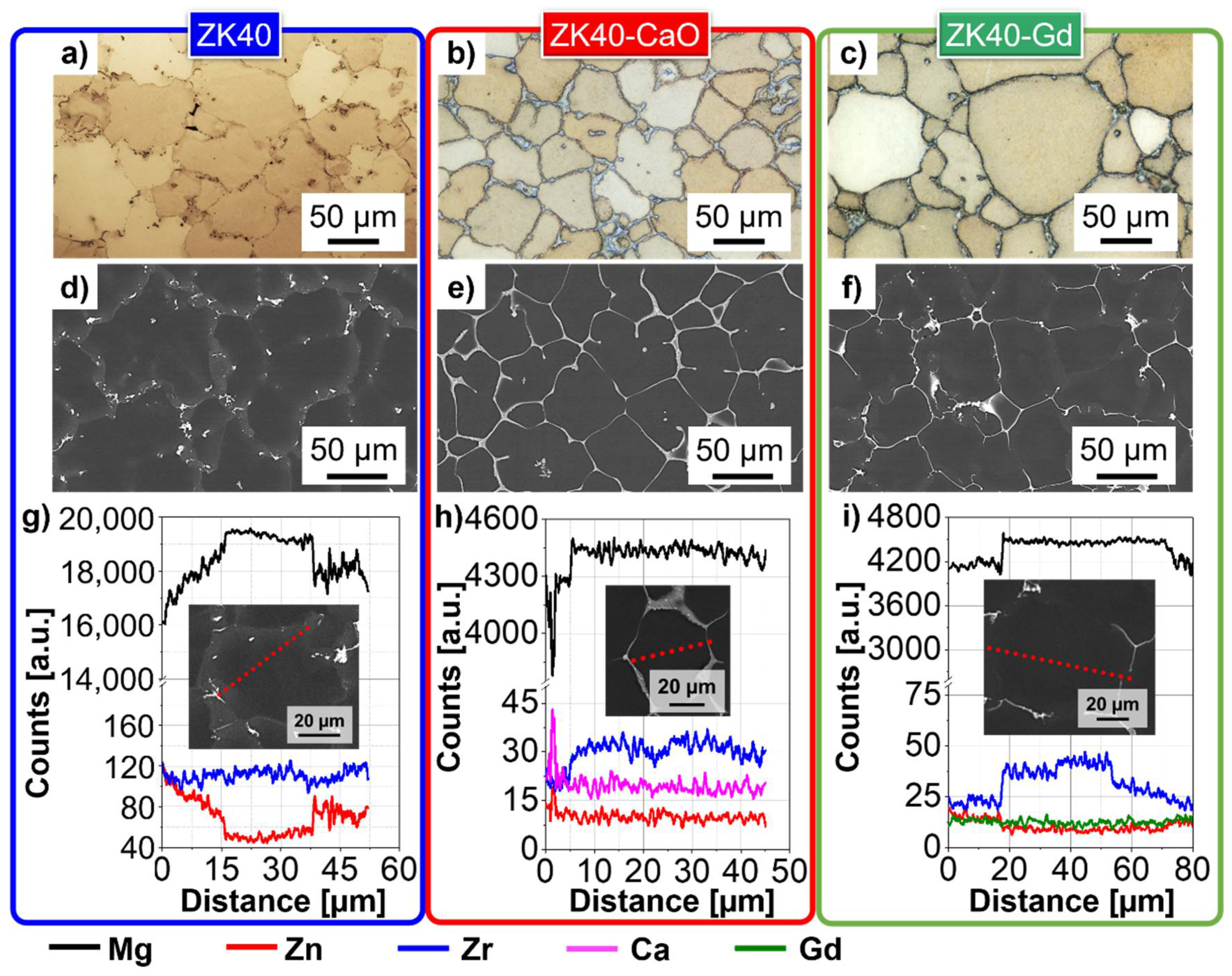
3.1. As-Cast Microstructures
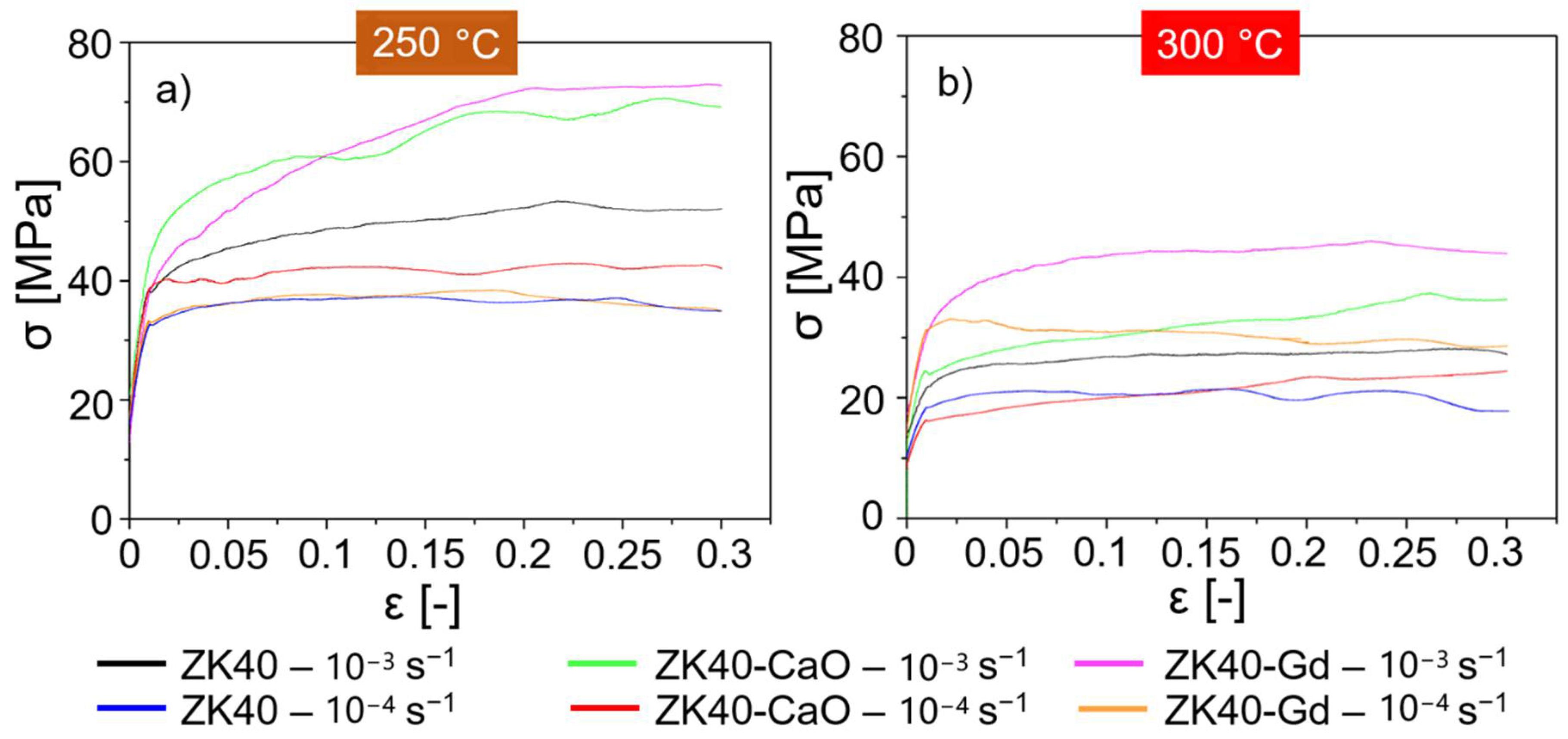
Light optical and BSE micrographs, as well as EDXS line scans, are used to characterise the as-cast microstructure of the investigated alloys, Figure 1. The light optical micrographs (Figure 1a–c) shows equiaxed-like grains for the investigated alloys. The average grain size of the ZK40 was 72.4 ± 2.5 µm, 75.9 ± 5.0 µm for the ZK40-CaO. The coarse and fine-grained ZK40-Gd gives rise to two different grain distribution with a global average of 46.1 ± 9.1 µm. The average size of the fine grains is 30.1 ± 4.2 µm, while coarse grains were 81.9 ± 9.2 µm. Intermetallic compounds are formed at grain boundaries for the ZK40 alloy, Figure 1d. A near-continuous network of intermetallic compounds is formed along the grain boundaries for the ZK40-CaO alloy, Figure 1e. Similarly, the ZK40-Gd exhibits a near-continuous network of intermetallic compounds along the grain boundaries, Figure 1f. The volume fraction of second phases is 1.6 ± 0.5%, 6.5 ± 0.9%, and 5.7 ± 1.0% for ZK40, ZK40-CaO and ZK40-Gd, respectively. The ZK40 alloy contains MgZn2 phase, as shown in [48,49]. The ZK40-CaO and ZK40-Gd contain Ca2Mg6Zn3 and (Mg, Zn)3Gd2, respectively [48,49]. Figure 1g–i shows the EDXS line scans for the investigated alloys. In ZK40 and ZK40-Gd, Zn segregates and its concentration is higher near grain boundaries. Zn segregation is near neglectable in ZK40-CaO. Inverse segregation of Zr occurs in ZK40-CaO and ZK40-Gd. A small amount of Ca and Gd are detected in the α-Mg matrix of the ZK40-CaO and ZK40-Gd, respectively. However, no appreciable segregation of Ca or Gd is observed. A more detailed microstructure investigation of the as-cast alloys used in this study can be found in [48,49].

3.2. Flow Curves

The measured flow curves at 250 °C and 300 °C are shown in Figure 2a,b, respectively. ZK40-Gd and ZK40-CaO exhibit similar behaviour at 250 °C and 0.001 s−1. A fast work hardening occurs once the plastic regime is reached, followed by a progressive decrease in work hardening until a plateau at a true strain of ~0.2. This plateau does not necessarily correspond to the steady-state condition that can be achieved at larger strains. Hradilová et al. [50] investigated alloys of the similar chemical composition of the ZK40-CaO and showed that DDRX could take place at strains larger than 0.3, leading to flow softening. The ZK40 exhibits less pronounced work hardening and lower flow stresses than ZK40-CaO and ZK40-Gd, although the plateau is also reached at a true strain of ~0.2. A decrease in the strain rate to 0.0001 s−1 leads to lower flow stresses and very low work hardening for all alloys. Once the plastic deformation starts, a rapid work hardening is followed by a plateau at strains lower than 0.1. The ZK40 and ZK40-Gd exhibit similar behaviour at 250 °C and 0.0001 s−1, while ZK40-CaO exhibits slightly higher flow stress.
The increase in temperature to 300 °C leads to a pronounced reduction in the maximum stress for the investigated alloys (~50% of the respective ones at 250 °C), Figure 2b. The following occurs for deformation at 300 °C and 0.001 s−1: ZK40 and ZK40-Gd show fast work hardening and reach a plateau at low strains (~0.1), while ZK40-CaO shows a nearly constant but minimal work hardening. The decrease of strain rate to 0.0001 s−1 leads to three different behaviours: (a) ZK40 shows a rapid work hardening followed by a plateau at a true strain of ~0.05; (b) ZK40-CaO shows similar flow stresses compared to ZK40 but a nearly constant work hardening; (c) After a rapid work hardening, an almost continuous flow softening occurs for the ZK40-Gd.

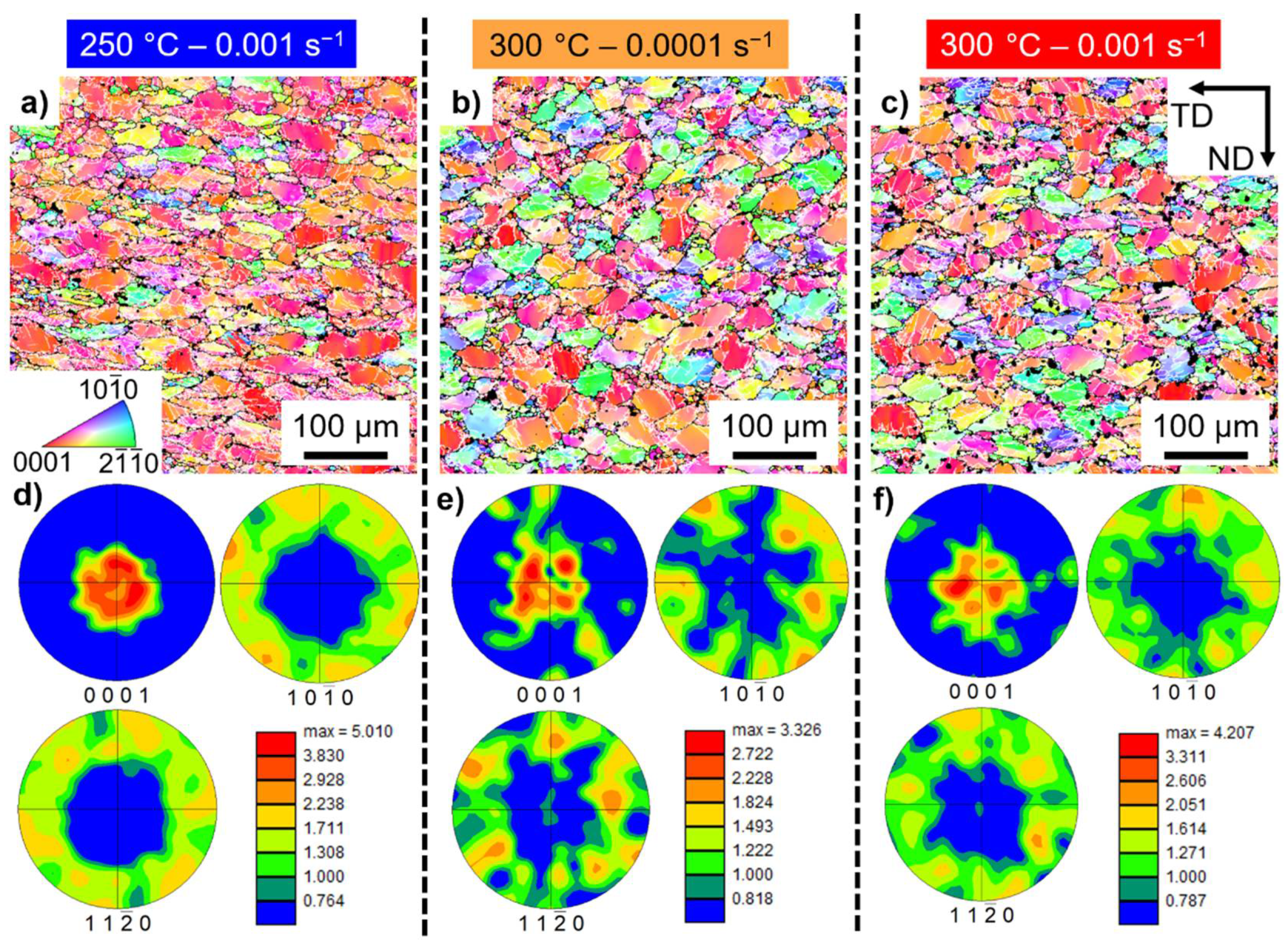
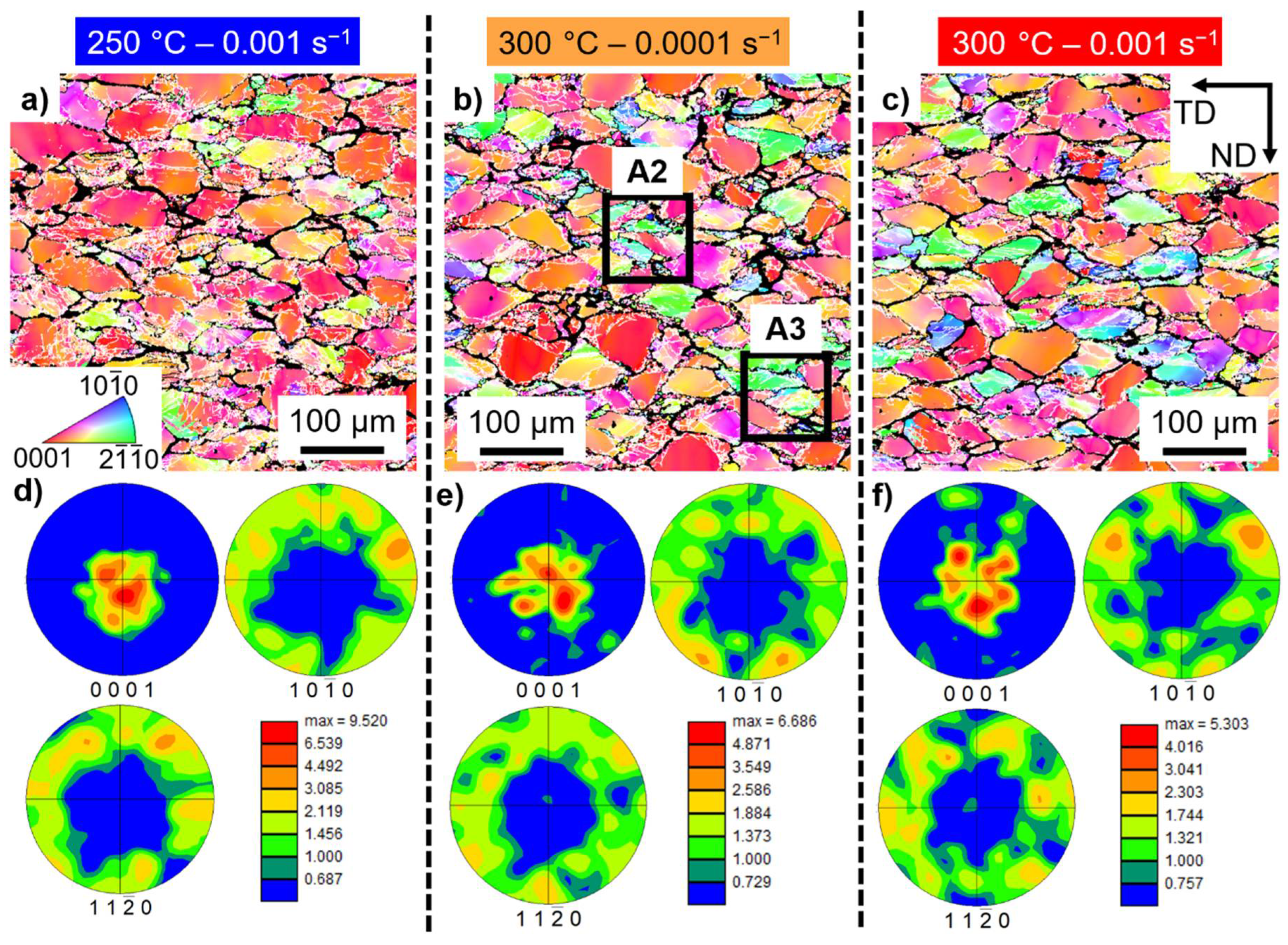
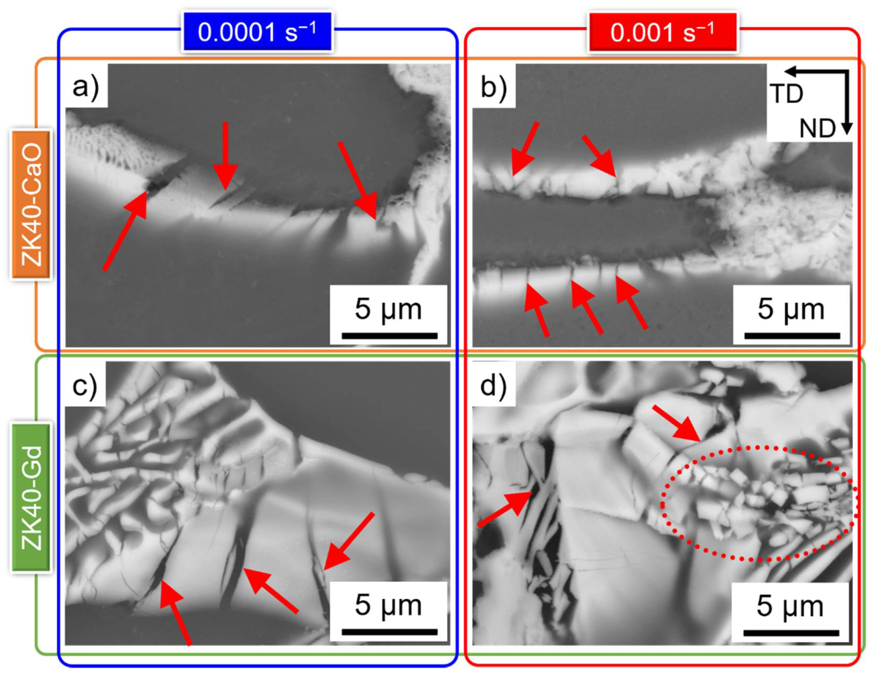
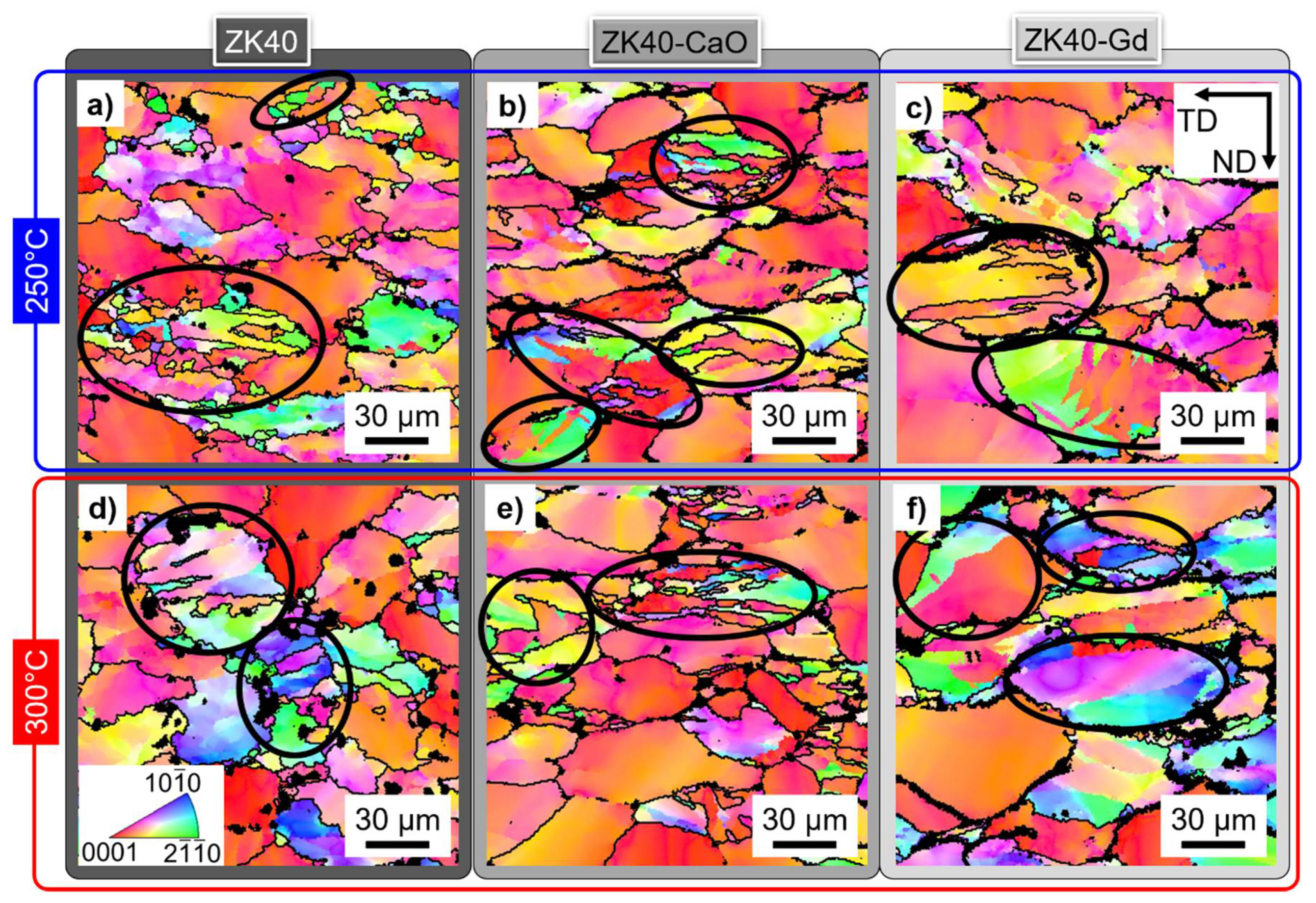
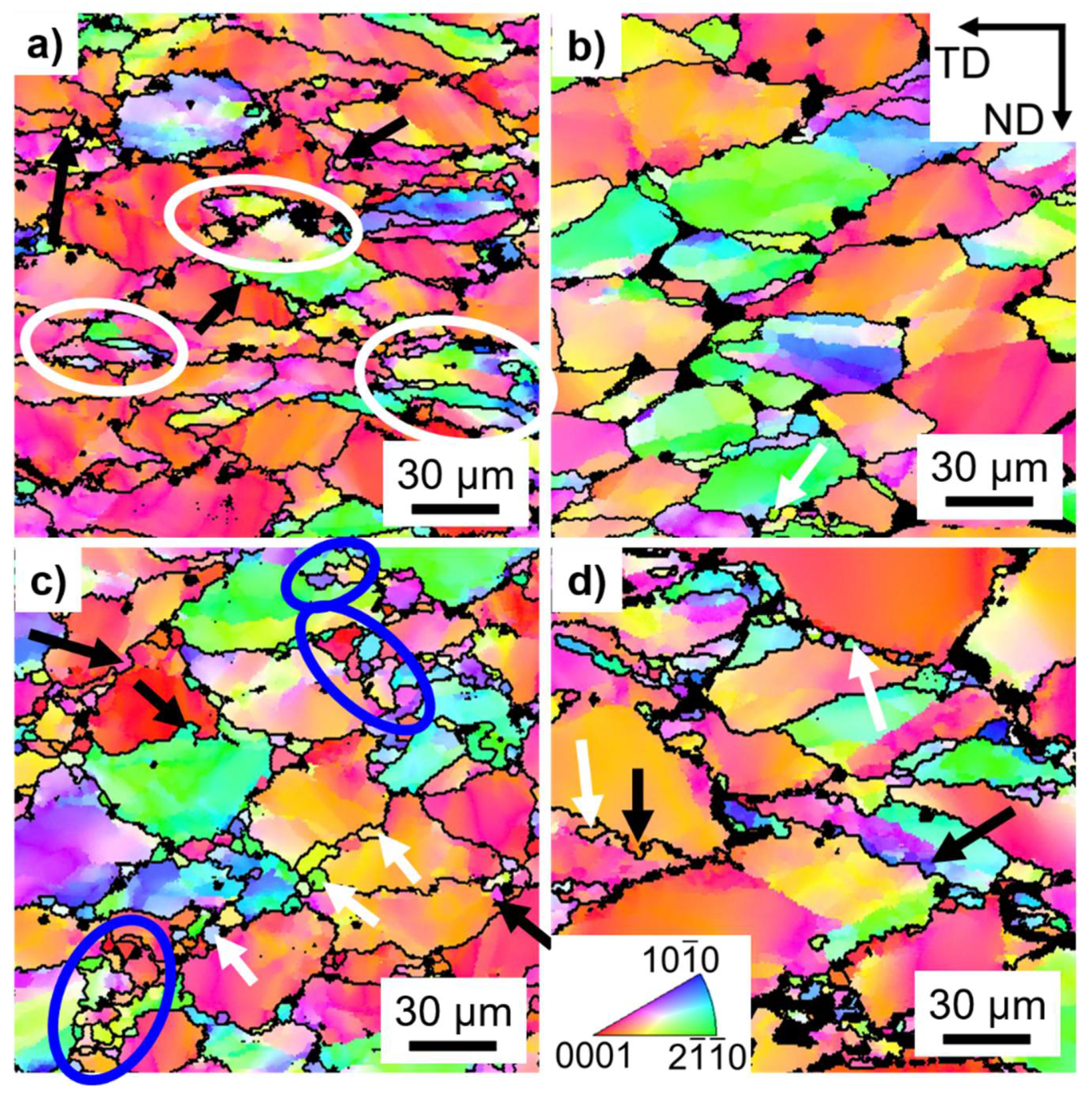
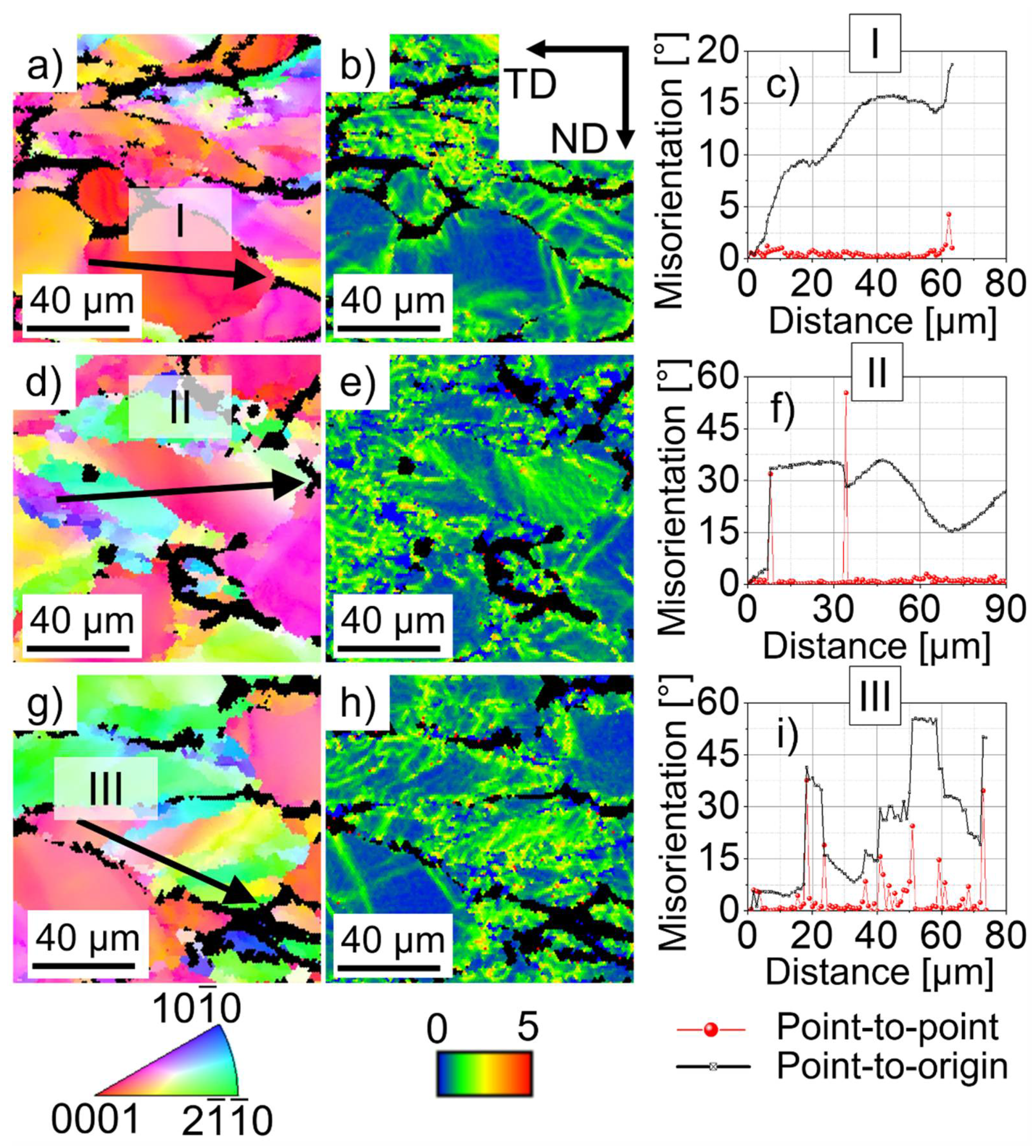
3.3. Deformed Microstructures

The microstructure of the Mg-matrix of the deformed ZK40 up to 0.3 strain is shown in Figure 3. The inverse pole figure (IPF) maps (Figure 3a–c) show that the formed microstructural features are comparable: pronounced basal texture, a network of low angle grain boundaries indicated by white lines and misorientation spread within the grain. The pronounced basal texture is also visible in the pole figures in Figure 3c–f. A slightly more isotropic deformation seems to occur at 300 °C and 0.0001 s−1, as indicated by the smallest maximum texture index and more random distribution of poles in the pole figure.
Figure 4 shows the EBSD results for the deformed ZK40-CaO up to 0.3 strain. Similar to the ZK40, the formation of low-angle grain boundaries was more concentrated in regions near the grain boundaries, while intensive misorientation spread is present in nearly all grains. The maximum index of texture is slightly higher than that for the ZK40. The deformation seems to be less anisotropic at 300 °C and 0.0001 s−1.
Figure 5 shows the deformed microstructure of the α-Mg matrix for the ZK40-Gd up to 0.3 strain. The microstructure is comparable to the ZK40 and ZK40-CaO consisting of an intricated network of low angle grain boundaries, a high level of misorientation spread within the α-Mg and intense basal texture. The isotropic degree of deformation is higher at 300 °C than at 250 °C, as grains of different orientations are depicted. Besides, the pole figures show a more diffuse basal texture at 300 °C and poles in other directions than the basal one, Figure 5e,f. The most isotropic condition was the 300 °C and 0.001 s−1 for the ZK40-Gd, instead of 300 °C and 0.0001 s−1 observed for ZK40 and ZK40-CaO.
Figure 6 shows the quantification of the overall microstructural features for the investigated conditions. The boundary density ( S v ) is calculated as the total line length of each boundary divided by the measurement area and is shown in Figure 6a–c for the ZK40, ZK40-CaO and ZK40-Gd, respectively. Higher S v values of low angle grain boundaries are observed at 250 °C compared to 300 °C. Slightly higher S v values of low angle grain boundaries are measured at 0.001 s−1 than 0.0001 s−1 for the ZK40 and ZK40-CaO. On the other hand, ZK40-Gd shows slightly lower values of low angle grain boundaries at 250 °C and 0.001 s−1 than those at 250 °C and 0.0001 s−1. ZK40 shows the highest values of S v of low angle high angle grain boundaries, while comparable values are found for ZK40-CaO and ZK40-Gd.
The initial grain size indicates the initial value of the boundary density of high angle grain boundaries. Smaller grains correspond to higher boundary density. The initial grain size of ZK40 and ZK40-CaO are comparable, while ZK40-Gd shows a slightly smaller overall grain size. ZK40-Gd deformed at 300 °C, and 0.001 s−1 shows the smallest value of S v for the high angle grain boundaries, 5 × 10⁴ m−1. ZK40 deformed at 250 °C, and 0.001 s−1 shows the highest value, 15 × 104 m−1. The three times the higher value for the ZK40 indicates that formation of high angle grain boundaries occurs during deformation in this alloy.
Figure 6d–f shows the fraction of each boundary type for the ZK40, ZK40-CaO and ZK40-Gd, respectively. The low angle grain boundaries in the range between 2° and 5° are the predominant boundary type for all investigated conditions. ZK40 shows the highest fraction of high angle grain boundaries, except at 300 °C and 0.001 s−1, where the fraction of high angle grain boundaries is comparable with that for ZK40-CaO. ZK40 shows similar values of fraction of low angle grain boundaries in the range between 2° to 5° for the investigated conditions. ZK40-Gd deformed at 0.001 s−1 shows a higher fraction of low angle grain boundaries in the range between 2° and 5° compared to 0.0001 s−1. ZK40-CaO shows a non-linear dependency on temperature and strain rate.
The plastic deformation occurs in the α-Mg matrix, while the brittle intermetallic compounds fragments during deformation, as shown in Figure 7. The intermetallic compounds present in the ZK40 are isolated and in low volume fraction. They are not shown here because they do not exhibit the brittle behaviour like the intermetallic compounds present in the modified alloys. The intermetallic compound formed in the ZK40-Gd has a typical lamellar structure [48]. Its fracture leads to the formation of fragmented fine particles of that phase, as indicated by the dashed red circle in Figure 7d. The intermetallic compound formed in the ZK40-CaO has a mixed structure of platelet and fine lamellar structure [49]. The red arrows in Figure 7a,b indicate the cracks that fragment the network of intermetallic compounds into smaller particles.

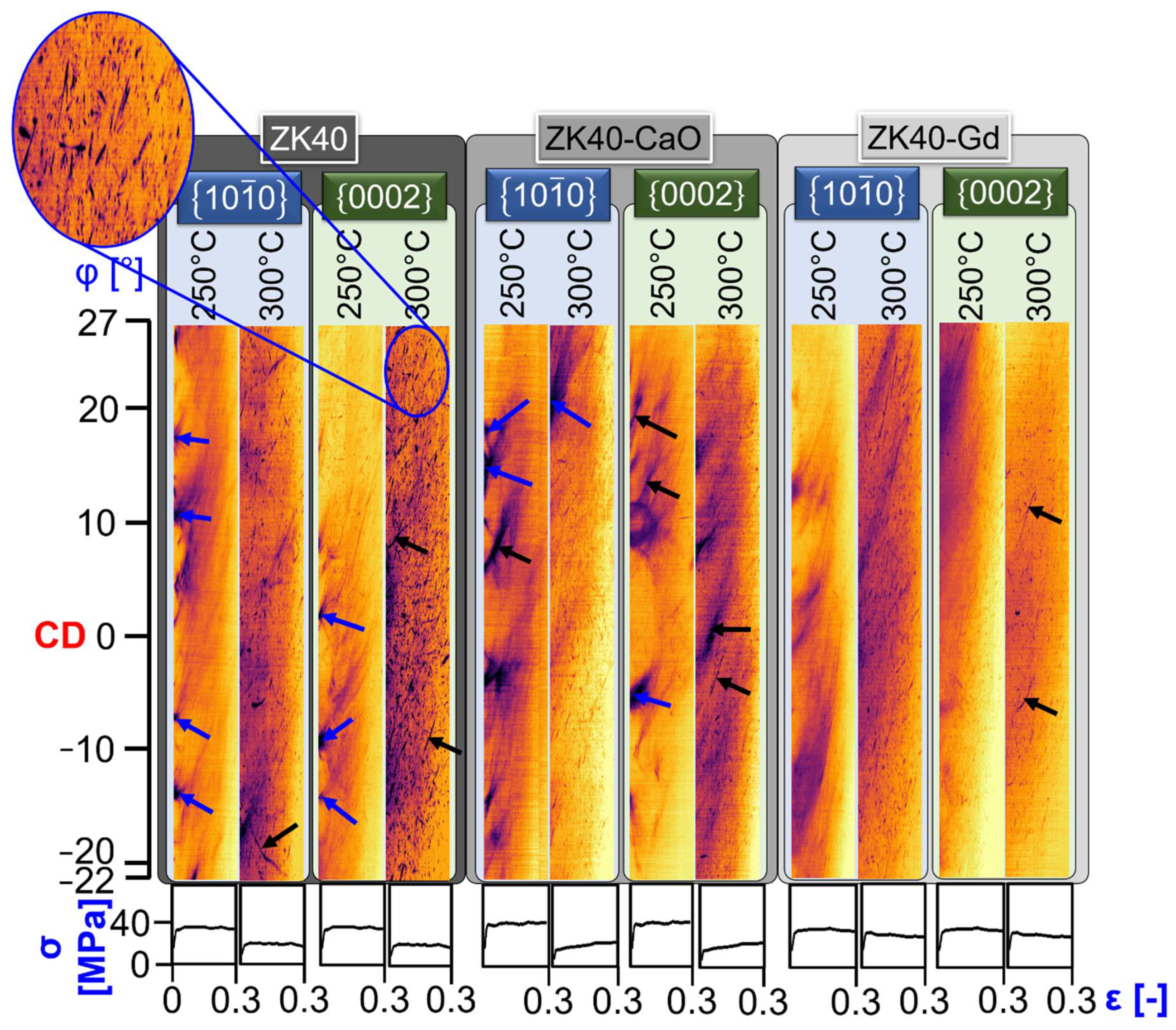
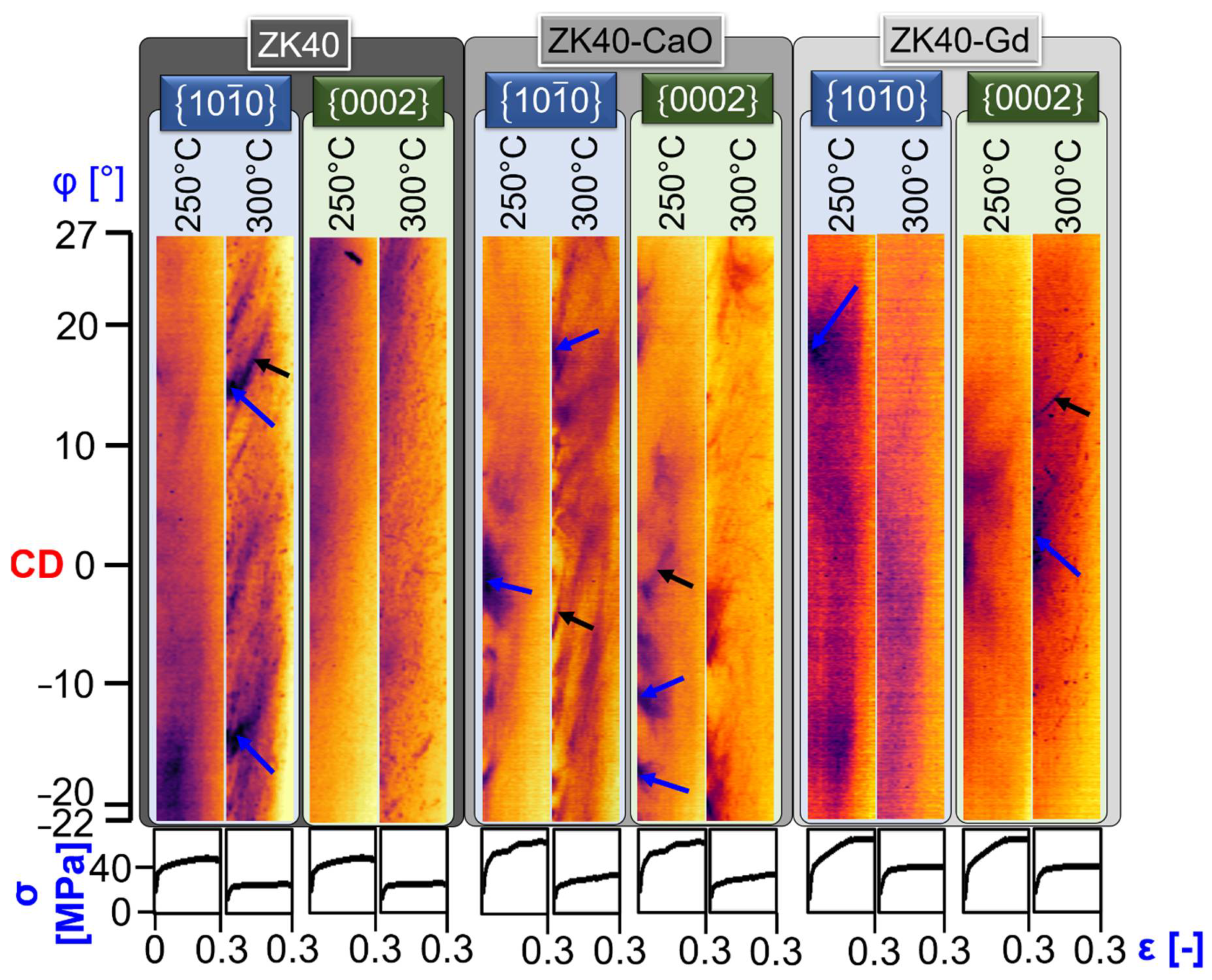
3.4. Insights from In-Situ Synchrotron Radiation Diffraction

The azimuthal-strain plots of the { 10 1 ¯ 0 } and { 0002 } are shown in Figure 8 for the deformed samples at 0.0001 s−1. The acquisition of the Debye-Scherrer rings in reflection mode, and the detector size limits the range of azimuthal from −22° to 27°. The deformation starts with an intense spread of orientation in the diffraction rings and the decay in the intensity of the diffraction signal, interpreted as the formation of misorientation within α-Mg because of rapid formation of dislocations due to glide, i.e., work hardening. This process is indicated in Figure 8 by the blue arrows. Deformation twinning can also occur at the early stages of deformation. However, it is not straightforward to be depicted by the obtained azimuthal-strain-plots. The result is the progressive disappearance of the Bragg spots in the azimuthal range shown in Figure 8.
The bending of the timelines is a second phenomenon interpreted from azimuthal-time plots, as indicated by the black arrows in Figure 8. The bending of the timelines shows that the plastic deformation leads to lattice rotation in some grains that bends the grain orientation in the azimuthal-time plots. The progressive disappearance of those timelines indicates those grains are not in Bragg position as a consequence of the pronounced basal texture formation, as shown in Figure 3, Figure 4 and Figure 5. Dynamic recovery causes the thinning of the timelines due to the reorganisation of dislocations, diminishing the local misorientation spread. Finally, the general spread in orientation and decay in intensity of the timelines occurs due to the ongoing formation of misorientation within the grains as a mechanism of plastic deformation accommodation.
Despite the comparable azimuthal-strain plots at 250 °C in Figure 8 for the investigated conditions, there is a significant difference between 250 °C and 300 °C: new spots are observed at 300 °C, as highlighted in the magnified area, and is more pronounced for the ZK40. The spotty characteristic of the azimuthal-strain plots can occur due to:
  • Twinning: the progressive appearance of a timeline in a crystallographic plane with the simultaneous and progressive disappearance of the timeline corresponding to the parent grain in another crystallographic plane.
  • DDRX: nucleation and growth of new grains that appear in the gauge volume and as new timelines.
The observed new spots and timelines likely correspond to the formation of new grains since they appear as a thinning of diffuse regions, and those crystals rotate notably. Their subsequent disappearance can be attributed to:
  • Sufficiently high local plastic deformation leads to lattice rotation of the formed grains, consequently, to the disappearance of their corresponding timelines.
  • A fraction of the new grains can be pushed away from the gauge volume. Oppositely, new ones can enter the gauge volume, leading to the appearance of new spots.
The azimuthal-time plots of the of the { 10 1 ¯ 0 } and { 0002 } are shown in Figure 9 for the deformed samples at 0.001 s−1. Similar to the azimuthal-strain plots obtained for the 0.0001 s−1 (Figure 8), the deformation of the investigated alloys at 0.001 s−1 leads to the formation of:
  • Misorientation spread: the intense spread of orientation in the diffraction rings and the decay in the intensity of the diffraction signal.
  • Crystal and subgrain rotation: bending of the timelines.
The spread of crystal orientation and the disappearance of the timelines show the first phenomenon. The blue arrows in Figure 9 and the diffuse formation timelines in Figure 9 indicate the misorientation spread. The black arrows in Figure 9 indicate the second phenomenon. The timelines in the azimuthal-strain plots for 0.001 s−1 are more diffuse than those of the deformation at 0.0001 s−1 (Figure 8) because of:
  • The stack of less Debye–Scherrer rings: 10% of the ones used for the 0.0001 s−1
  • Higher dislocation density and higher misorientation spread within the grains formed at higher strain rates.

4. Discussion

The in-situ and ex-situ results for the deformation at moderate temperatures of ZK40 alloy and modified ones with individual addition of Ca and Gd show that dynamic recovery is the primary restoration mechanism of the α-Mg up to the investigated strain. Simultaneously, the brittle behaviour of the intermetallic compounds leads to their fragmentation and, consequently, flow softening. Figure 3, Figure 4 and Figure 5 elucidate the role of dynamic recovery, where the formation of a substructure with low angle grain boundaries is present for all conditions. Figure 6 shows the significant fraction of low angle grain boundaries in the range between 2° to 5° that are typically cell or subgrain boundaries formed by the reorganisation of dislocations via dynamic recovery. Their fraction is the highest among the measured boundary types in all investigated cases. The formed boundaries between 5° and 15° are correlated to a higher level of local plastic deformation, leading to a higher degree of local lattice rotation. The plastic deformation is accommodated either by the formation of misorientation spread through the α-Mg matrix, slip bands, and formation of a band-like structure or by dynamic recovery and organised boundaries. The plateau that follows the work hardening in the flow stresses in Figure 2 occurs when the consumption of dislocation via dynamic recovery balances their production.
However, dynamic recovery does not occur homogeneously within the α-Mg grain. Figure 10 shows the kernel average misorientation analysis for the deformed alloys at 300 s−1 and 0.001 s−1. The kernel average misorientation distribution, Figure 10d shows nearly the same distributions for the three alloys. The maps, though, shows that the formed boundaries distribute more homogeneously for the ZK40 alloy. At the same time, the new boundaries localise in the vicinity of intermetallic compounds and within individual grains for the ZK40-CaO. Thus, Ca addition seems to hinder the reorganisation of dislocations into low angle grain boundaries. ZK40-Gd shows an intermediate behaviour, where a more homogeneous substructure is formed compared to the ZK40-CaO, but less homogeneous compared to the ZK40.
Dynamic recovery is the major but not the only restoration mechanism for the investigated deformation conditions. Complementary to Figure 3, Figure 4, Figure 5 and Figure 11 shows inverse pole figure maps in higher resolution of the deformed alloys at 0.001 s−1. Despite the comparable overall microstructural features (Figure 3, Figure 4 and Figure 5) for investigated alloys and small differences concerning the different deformation conditions, the differences are notable on the local scale. Black ellipses highlight the presence of microstructural features that resembles deformation twins. The presence of misorientation spread, different orientations and boundaries within those regions indicate that if they were deformation twins, they were formed in an early stage of deformation followed by further local lattice rotation and dynamic recovery. Hradilová et al. [50] showed similar microstructural features for Mg-Zn-Ca alloys deformed in a similar temperature range. They explained those features as the formation of tensile twins followed by accumulation of dislocations at the twin boundaries, dynamic recovery and the formation of boundaries within the twins. Finally, the higher stored energy at twins [51] leads to the bulging of new grains [50]. The first slope of work hardening observed in Figure 2a and more evident for the ZK40-CaO and ZK40-Gd can correspond to the formation of twins, while the second slope of work hardening before achieved plateau-like flow stress can correspond to twin growth and increment of dislocation density within them. The negligible presence of twins at the post-mortem microstructure at 0.3 strain agrees with the observation of Barnett et al. [52] that twinning is unlikely to occur if slip starts to dominate at larger strains. Twinning as a predominant mechanism at the beginning of deformation is also predicted due to the relatively large initial grain size [53,54] for the investigated alloys. Therefore, DRX at 0.001 s−1 seems to occur due to the nucleation and growth of new grains via DDRX at twinned regions at the early stages of deformation and is more pronounced for the ZK40 alloy.
The azimuthal-strain plots in Figure 8 show the presence of new spots. It is clarified by the formation of new grains at 0.0001 s−1, as shown in Figure 12. Two mechanisms are proposed:
  • Twins that recover and promote nucleation of new DDRX grains as explained by Hradilová et al. [50] and indicated by the blue ellipses in Figure 12c.
  • Pile-up of dislocation along grain boundaries and along intermetallic compounds leading to bulging of new grains via DDRX, as indicated by the black arrows in Figure 12, followed by growth as indicated by the white arrow arrows in Figure 12.
The azimuthal-strain plots in Figure 8 show that new spots are evident at 300 °C and negligible at 250 °C. The comparison between Figure 12a,b clarifies the different DRX mechanisms for the ZK40 at 250 °C and 300 °C, respectively. Despite a small fraction of DDRX grains observed at 250 °C, as indicated by the black arrows in Figure 12a, their presence is notably more pronounced at 300 °C. At 250 °C, the formation of new grains occurs via:
  • The formation of a substructure followed by CDRX, as evidenced in the azimuthal-strain plots, Figure 8: firstly, the intense spread of orientation in the diffraction rings and the decay in the intensity of the diffraction signal is associated with the misorientation spread and the multiplication of dislocations. It is followed by the bending and thinning of the timelines associated with subgrain rotation and dynamic recovery, respectively. The white ellipses in Figure 12a indicate regions where subgrains of different orientations are found within a grain. As proposed by Galiev et al. [12], extensive cross-slip at lower temperature leads to dislocation rearrangements into low angle grain boundaries networks, followed by CDRX.
  • Bulging of new grains via DDRX indicated by the black arrows in Figure 12a.
Thus, higher temperatures promote DDRX for the ZK40 due to higher boundary mobility and higher dislocation climb activity, promoting bulging of the deformed grain boundaries and the growth of new grains. The controlling mechanisms are, though, a function not only of temperature but also of strain. Moreover, different mechanisms can co-occur, as also observed by Galiyev et al. [12].
The addition of Gd or Ca also has an impact on the DRX kinetics. The presence of recrystallised grains is more pronounced for the ZK40 (Figure 12a,b), while Gd addition leads to the formation of a lower amount of new grains at 300 °C and 0.0001 s−1 up to the strain of 0.3, as indicated in Figure 12d. On the other hand, the presence of new grains at 300 °C and 0.0001 s−1 seems negligible for the ZK40-CaO. Hradilová et al. [50] showed that the peak stress is higher or equal to 0.3 for alloys of similar composition. Following the assumption proposed by Galiyev et al. [12] for a ZK60 alloy, Ca seems to modify the diagram of controlling mechanisms so that each field shifts to higher strains and higher temperatures. Thus, Ca additions promote twinning, reduces climb and bulging of new grains, retarding DDRX in Mg-Zn alloys.
Gd also seems to hinder DDRX. Despite the slightly smaller initial grain size than the ZK40 (Figure 1), the boundary density of high angle grain boundaries is smaller for the deformed ZK40-Gd up to 0.3 of a strain than the ZK40 (Figure 6). This result seems contradictory with the finding of Hoseini-Athar et al. [28], which showed that the addition of Gd to Mg-Zn alloys reduces the segregation of elements in the α-Mg, leading to the increment of DDRX kinetics due to a reduction in solute drag.
Figure 1g–i shows that small content of Ca, and Gd is present in the α-Mg matrix and that the segregation of Zn and Zr is pronounced. The ZK40 alloy shows mostly higher segregation of Zn. Figure 13 shows the EDXS maps measured simultaneously with EBSD for the Zn segregation in the deformed samples at 300 °C and 0.0001 s−1. The segregation of Zn is still present after deformation and more pronounced for the ZK40, Figure 13a. While the investigated alloys by Hoseini-Athar et al. [28] contained isolated intermetallic particles, the investigated ZK40-Gd has a semi-continuous network of intermetallic compounds along the grain boundaries. Due to the higher strength, the network of (Mg,Zn)3Gd2 withstand an elevated part of the stress until the network starts to fragment (Figure 7). Then, the load is progressively transferred into the α-Mg, leading to flow softening [17], as shown in Figure 2. Therefore, until the semi-continuous network of (Mg,Zn)3Gd2 withstands the load, the plastic deformation is limited in the α-Mg matrix. Furthermore, the α-Mg deforms near the intermetallic compounds, evident by the formation of boundaries preferentially along grains boundaries. Therefore, the formation of a semi-continuous network of (Mg,Zn)3Gd2 reduces the role of DDRX in ZK40-Gd.
The flow stress behaviour in Figure 2b and the formation of new grains are directly correlated: the ZK40 and the ZK40-Gd exhibit a flow softening due to the formation of recrystallised grains, while ZK40-CaO exhibits a slight work hardening, where the formation of new grains is nearly absent. The fragmentation of the intermetallic compounds, as shown in Figure 7, seems to contribute to an additional softening for the ZK40-Gd. However, the fragmentation of the intermetallic compounds seems to play a minor role in the flow stress evolution for the ZK40-CaO.
Finally, the mechanisms of microstructure formation and the role of dynamic recovery are derived from the interpretation of the microstructure features, Figure 14. Figure 14a,d,g shows a notable misorientation spread in the inverse pole figure maps shown as a progressive change in orientation within each grain. Besides, Figure 14c illustrates the misorientation profile I with variations in misorientation without the formation of boundaries. The kernel average misorientation map (Figure 14b) also indicates diffuse boundaries within the observed grain, indicating an early degree of the reorganisation of dislocations via dynamic recovery. The misorientation profile II in Figure 14f shows a region that resembles the morphology of a twin. The boundary misorientation is far from 90° (typically for the tensile deformation twins), indicating that the feature cannot be classified as a twin. However, it suggests that it corresponds to a twin formed at early stages of deformation that further deformed forming misorientation spread and boundaries within the twinned region, as proposed by Hradilová et al. [50]. The kernel average misorientation map in Figure 14e shows a diffuse pattern within a parent un-twined grain, indicating the parent grain also accommodates further plastic deformation.
The increase in misorientation spread within α-Mg occurs due to lattice rotation caused by the formation of geometrically necessary dislocations or the formation of LAGBs [42]. On the other hand, the rotation of the subgrains with lower Taylor factor (softer subgrains) withstands larger plastic deformation. Both phenomena indicate DRV as the predominant mechanism for the microstructure evolution of the α-Mg, corroborating with the interpretation of the above-observed microstructures. Complementary, Figure 14g shows a grain with a band-like structure that resembles twins. The corresponding misorientation profile in Figure 14i shows that the boundary misorientations are smaller than 40°. The band-structure, thus, is a result of a substantial reorganisation of the initial twin by pronounced local lattice rotation and formation of boundaries, visible in the kernel average misorientation map in Figure 14h.

5. Summary and Conclusions

The deformation behaviour at 250 °C and 300 °C of the ZK40 alloy and modified ZK40 alloys with individual additions of CaO and Gd is investigated using in-situ synchrotron radiation diffraction and ex-situ characterisation techniques. The restoration mechanisms are derived from the interpretation of the microstructure features up to deformation of 0.3 of true strain. The following conclusion can be drawn:
  • Additions of Ca and Gd increase the flow stress for the ZK40 alloys deformed at intermediated temperatures.
  • Flow softening of ZK40-Gd at 300 °C occurs due to discontinuous dynamic recrystallisation and fragmentation of the intermetallic compounds.
  • The fragmentation of intermetallic compounds seems to play a minor role in flow softening for the ZK40-CaO. Either only work hardening or a plateau in the flow stress occurs for this alloy up to the investigated strain.
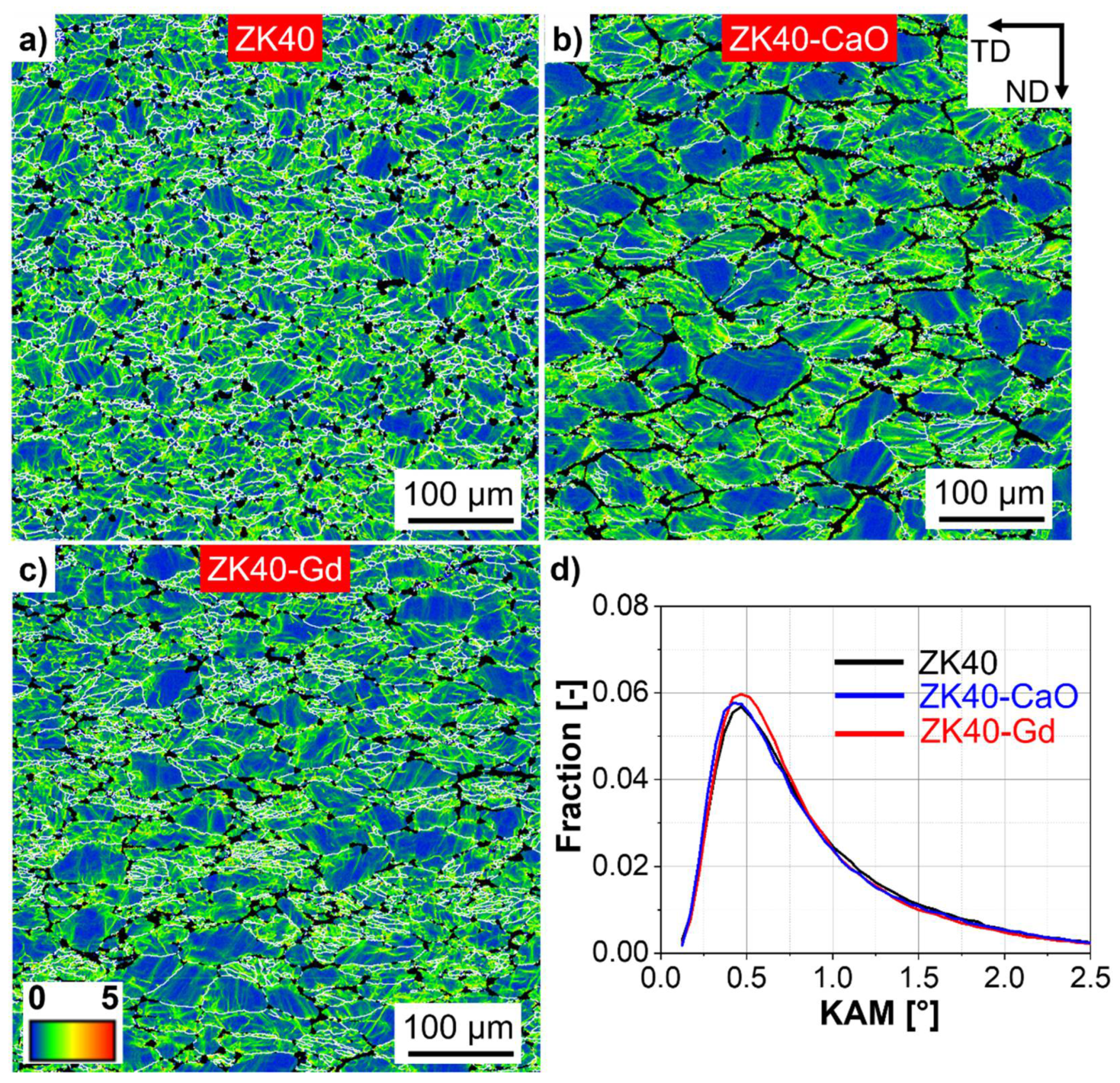
  • The controlling mechanisms that accommodate plastic deformation depend on the strain rate, temperature and strain, and are listed: misorientation spread within the α-Mg resulting from dislocation slip, the formation of low angle grain boundaries via dynamic recovery, twinning and dynamic recrystallisation.
  • Dynamic recovery is the predominant restoration mechanism for the investigated alloys in all conditions.
  • The formation of low angle grain boundaries occurs more homogeneously within the grain for ZK40 and ZK40-Gd. The Ca addition to the ZK40 seem to hinder the formation of subgrain boundaries during deformation. The formed boundaries are localised at the vicinity of original grain boundaries after 0.3 strain.
  • Only the ZK40 deformed at 250 °C and 0.0001 s−1 shows continuous dynamic recrystallisation. This occurs via the formation of subgrains and the increase in boundary misorientation due to the progressive accumulation of dislocations via extensive cross-slip. It competes with discontinuous dynamic recrystallisation that occurs via bulging of subgrains and growth.
  • Discontinuous dynamic recrystallisation is more pronounced at 300 °C compared to 250 °C and is present in the ZK40 and ZK40-Gd. Formation of an established subgrain structure that could lead to continuous dynamic recrystallisation is not found at 300 °C in any alloy.
  • Ca addition to the ZK40 inhibits discontinuous dynamic recrystallisation.
  • Gd addition to the ZK40 forms a semi-continuous network of intermetallic compounds that takes the load until its fragmentation, limiting the plastic deformation of the α-Mg, localising that at the grain boundaries. Thus, discontinuous dynamic recrystallisation is more limited for the ZK40-Gd compared to the ZK40.
  • Tensile twins are rarely found in the microstructure after 0.3 strain. However, regions with similar morphology of deformation twins found throughout the microstructure for all conditions and alloys indicate twinning occurs at early stages of deformation followed by recovery and boundary formation within the twinned portion of the grains. New recrystallised grains formed in those regions are only found for the ZK40 alloy.

Author Contributions

Conceptualization, R.H.B., L.H.M.G., J.A.Á.D., D.T., C.L.M., N.H. and H.C.P.; Data curation, R.H.B.; Investigation, R.H.B., L.H.M.G., J.A.Á.D. and E.P.d.S.; Methodology, R.H.B., L.H.M.G., N.H. and H.C.P.; Resources, N.H. and H.C.P.; Software, R.H.B. and L.H.M.G.; Supervision, H.C.P.; Validation, R.H.B. and L.H.M.G.; Writing—original draft, R.H.B.; Writing—review & editing, L.H.M.G., J.A.Á.D., E.P.d.S., D.T., C.L.M., N.H. and H.C.P. All authors have read and agreed to the published version of the manuscript.

Funding

This research received no external funding.

Acknowledgments

The authors would like to thank the Brazilian Synchrotron Light Laboratory (LNLS) CNPEM/MCTIC for the use of the XTMS beamline. RHB acknowledges the CD-Laboratory for Design of High-Performance Alloys by Thermomechanical Processing with the support of the Christian Doppler Forschungsgesellschaft. L.H.M.G. acknowledges the financial Support of Coordenação de Aperfeiçoamento de Pessoal de Nível Superior—Brasil (CAPES) (Process No. 88882.180165/2018-01). J.A.Á.D. acknowledges CNPq for a postdoc scholarship (Grant No. 150215/2016-9). The authors sincerely acknowledge Maria Cecilia Poletti for fruitful and meaningful discussions. Open Access Funding by the Graz University of Technology.

Conflicts of Interest

The authors declare no conflict of interest.

Data Availability

The raw/processed data that support the findings of this study are available from the corresponding author, RHB, upon request.

References

  1. Luo, A. Applications: Aerospace, automotive and other structural applications of magnesium. In Fundamentals of Magnesium Alloy Metallurgy; Pekguleryuz, M.O., Kainer, K.U., Arslan Kaya, A., Eds.; Woodhead Publishing: Oxford, UK, 2013; pp. 266–316. [Google Scholar]
  2. Avedesian, M.; Baker, H. ASM Specialty Handbook: Magnesium and Magnesium Alloys; ASM International: Cleveland, OH, USA, 1999. [Google Scholar]
  3. Yoo, M.H.; Morris, J.R.; Ho, K.M.; Agnew, S.R. Nonbasal deformation modes of HCP metals and alloys: Role of dislocation source and mobility. Met. Mater. Trans. A 2002, 33, 813–822. [Google Scholar] [CrossRef]
  4. Ahlers, M. Stacking fault energy and mechanical properties. Metall. Trans. 1970, 1, 2415–2428. [Google Scholar] [CrossRef]
  5. Sun, Z.; Wu, H.; Cao, J.; Yin, Z. Modeling of continuous dynamic recrystallization of Al-Zn-Cu-Mg alloy during hot deformation based on the internal-state-variable (ISV) method. Int. J. Plast. 2018, 106, 73–87. [Google Scholar] [CrossRef]
  6. Humphreys, F.J.; Hatherly, M.; Humphreys, F.J.; Hatherly, M. Chapter 13—Hot Deformation and Dynamic Restoration. In Recrystallization and Related Annealing Phenomena; Elsevier: Oxford, UK, 2004; pp. 415–450. ISBN 9780080441641. [Google Scholar]
  7. Takaki, T.; Yoshimoto, C.; Yamanaka, A.; Tomita, Y. Multiscale modeling of hot-working with dynamic recrystallization by coupling microstructure evolution and macroscopic mechanical behavior. Int. J. Plast. 2014, 52, 105–116. [Google Scholar] [CrossRef]
  8. Li, H.; Wu, C.; Yang, H. Crystal plasticity modeling of the dynamic recrystallization of two-phase titanium alloys during isothermal processing. Int. J. Plast. 2013, 51, 271–291. [Google Scholar] [CrossRef]
  9. Blum, W.; Zhu, Q.; Merkel, R.; McQueen, H. Geometric dynamic recrystallization in hot torsion of Al 5Mg 0.6Mn (AA5083). Mater. Sci. Eng. A 1996, 205, 23–30. [Google Scholar] [CrossRef]
  10. Zhou, G.; Li, Z.; Li, D.; Peng, Y.; Zurob, H.S.; Wu, P. A polycrystal plasticity based discontinuous dynamic recrystallization simulation method and its application to copper. Int. J. Plast. 2017, 91, 48–76. [Google Scholar] [CrossRef]
  11. Gourdet, S.; Montheillet, F. A model of continuous dynamic recrystallization. Acta Mater. 2003, 51, 2685–2699. [Google Scholar] [CrossRef]
  12. Galiyev, A.; Kaibyshev, R.; Gottstein, G. Correlation of plastic deformation and dynamic recrystallization in magnesium alloy ZK60. Acta Mater. 2001, 49, 1199–1207. [Google Scholar] [CrossRef]
  13. Couret, A.; Caillard, D. An in situ study of prismatic glide in magnesium—I. The rate controlling mechanism. Acta Met. 1985, 33, 1447–1454. [Google Scholar] [CrossRef]
  14. Escaig, B. L’activation thermique des déviations sous faibles contraintes dans les structures hc et cc Par. Phys. Status Solidi (b) 1968, 28, 463–474. [Google Scholar] [CrossRef]
  15. Legrand, P.B. Relations entre la structure électronique et la facilité de glissement dans les métaux hexagonaux compacts. Philos. Mag. B 1984, 49, 171–184. [Google Scholar] [CrossRef]
  16. Wu, Y.-Z.; Yan, H.-G.; Zhu, S.-Q.; Chen, J.-H.; Liu, A.-M.; Liu, X.-L. Flow behavior and microstructure of ZK60 magnesium alloy compressed at high strain rate. Trans. Nonferrous Met. Soc. China 2014, 24, 930–939. [Google Scholar] [CrossRef]
  17. Buzolin, R.; Tolnai, D.; Mendis, C.L.; Stark, A.; Schell, N.; Pinto, H.; Kainer, K.; Hort, N. In situ synchrotron radiation diffraction study of the role of Gd, Nd on the elevated temperature compression behavior of ZK40. Mater. Sci. Eng. A 2015, 640, 129–136. [Google Scholar] [CrossRef]
  18. He, S.; Peng, L.; Zeng, X.; Ding, W.; Zhu, Y. Comparison of the microstructure and mechanical properties of a ZK60 alloy with and without 1.3 wt.% gadolinium addition. Mater. Sci. Eng. A 2006, 433, 175–181. [Google Scholar] [CrossRef]
  19. Zhou, H.; Zhang, Z.; Liu, C.; Wang, Q. Effect of Nd and Y on the microstructure and mechanical properties of ZK60 alloy. Mater. Sci. Eng. A 2007, 445, 1–6. [Google Scholar] [CrossRef]
  20. Ma, C.; Liu, M.; Wu, G.; Ding, W.; Zhu, Y. Tensile properties of extruded ZK60-RE alloys. Mater. Sci. Eng. A 2003, 349, 207–212. [Google Scholar] [CrossRef]
  21. Homma, T.; Mendis, C.; Hono, K.; Kamado, S. Effect of Zr addition on the mechanical properties of as-extruded Mg–Zn–Ca–Zr alloys. Mater. Sci. Eng. A 2010, 527, 2356–2362. [Google Scholar] [CrossRef]
  22. Li, Q.; Wang, Q.; Wang, Y.; Zeng, X.; Ding, W. Effect of Nd and Y addition on microstructure and mechanical properties of as-cast Mg–Zn–Zr alloy. J. Alloy. Compd. 2007, 427, 115–123. [Google Scholar] [CrossRef]
  23. Kim, J.M.; Park, J.S. Microstructure and tensile properties of Mg–Zn–Gd casting alloys. Int. J. Cast Met. Res. 2011, 24, 127–130. [Google Scholar] [CrossRef]
  24. Mordike, B. Creep-resistant magnesium alloys. Mater. Sci. Eng. A 2002, 324, 103–112. [Google Scholar] [CrossRef]
  25. Singh, A.; Somekawa, H.; Mukai, T. Compressive strength and yield asymmetry in extruded Mg–Zn–Ho alloys containing quasicrystal phase. Scr. Mater. 2007, 56, 935–938. [Google Scholar] [CrossRef]
  26. Stanford, N. Micro-alloying Mg with Y, Ce, Gd and La for texture modification—A comparative study. Mater. Sci. Eng. A 2010, 527, 2669–2677. [Google Scholar] [CrossRef]
  27. Bohlen, J.; Nürnberg, M.R.; Senn, J.W.; Letzig, D.; Agnew, S.R. The texture and anisotropy of magnesium–zinc–rare earth alloy sheets. Acta Mater. 2007, 55, 2101–2112. [Google Scholar] [CrossRef] [Green Version]
  28. Hoseini-Athar, M.; Mahmudi, R.; Babu, R.P.; Hedström, P. Effect of Zn addition on dynamic recrystallization behavior of Mg-2Gd alloy during high-temperature deformation. J. Alloy. Compd. 2019, 806, 1200–1206. [Google Scholar] [CrossRef]
  29. Kwak, T.; Lim, H.; Kim, W. Effect of Ca and CaO on the microstructure and hot compressive deformation behavior of Mg–9.5Zn–2.0Y alloy. Mater. Sci. Eng. A 2015, 648, 146–156. [Google Scholar] [CrossRef]
  30. Hofstetter, J.; Rüedi, S.; Baumgartner, I.; Kilian, H.; Mingler, B.; Povoden-Karadeniz, E.; Pogatscher, S.; Uggowitzer, P.; Löffler, J.F. Processing and microstructure–property relations of high-strength low-alloy (HSLA) Mg–Zn–Ca alloys. Acta Mater. 2015, 98, 423–432. [Google Scholar] [CrossRef]
  31. Suzuki, A.; Saddock, N.; TerBush, J.R.; Powell, B.; Jones, J.; Pollock, T. Precipitation Strengthening of a Mg-Al-Ca–Based AXJ530 Die-cast Alloy. Met. Mater. Trans. A 2008, 39, 696–702. [Google Scholar] [CrossRef]
  32. Luo, A.A. Recent magnesium alloy development for elevated temperature applications. Int. Mater. Rev. 2004, 49, 13–30. [Google Scholar] [CrossRef]
  33. Zhang, B.; Wang, Y.; Geng, L.; Lu, C. Effects of calcium on texture and mechanical properties of hot-extruded Mg–Zn–Ca alloys. Mater. Sci. Eng. A 2012, 539, 56–60. [Google Scholar] [CrossRef]
  34. Chino, Y.; Ueda, T.; Otomatsu, Y.; Sassa, K.; Huang, X.; Suzuki, K.; Mabuchi, M. Effects of Ca on Tensile Properties and Stretch Formability at Room Temperature in Mg-Zn and Mg-Al Alloys. Mater. Trans. 2011, 52, 1477–1482. [Google Scholar] [CrossRef] [Green Version]
  35. Wiese, B.; Mendis, C.L.; Tolnai, D.; Stark, A.; Schell, N.; Reichel, H.; Brückner, R.; Kainer, K.U.; Hort, N. CaO dissolution during melting and solidification of a Mg 10 wt.% CaO alloy detected with in situ synchrotron radiation diffraction. J. Alloy. Compd. 2015, 618, 64–66. [Google Scholar] [CrossRef] [Green Version]
  36. Buzolin, R.; Mendis, C.L.; Tolnai, D.; Stark, A.; Schell, N.; Pinto, H.; Kainer, K.; Hort, N. In situ synchrotron radiation diffraction investigation of the compression behaviour at 350 °C of ZK40 alloys with addition of CaO and Y. Mater. Sci. Eng. A 2016, 664, 2–9. [Google Scholar] [CrossRef] [Green Version]
  37. Kwak, T.; Kim, W. Hot compression behavior of the 1 wt% calcium containing Mg–8Al–0.5Zn (AZ80) alloy fabricated using electromagnetic casting technology. Mater. Sci. Eng. A 2014, 615, 222–230. [Google Scholar] [CrossRef]
  38. Canelo-Yubero, D.; Poletti, C.; Warchomicka, F.; Daniels, J.; Requena, G. Load partition and microstructural evolution during hot deformation of Ti-6Al-6V-2Sn matrix composites, and possible strengthening mechanisms. J. Alloy. Compd. 2018, 764, 937–946. [Google Scholar] [CrossRef]
  39. Lonardelli, I.; Gey, N.; Wenk, H.-R.; Humbert, M.; Vogel, S.C.; Lutterotti, L. In situ observation of texture evolution during α→β and β→α phase transformations in titanium alloys investigated by neutron diffraction. Acta Mater. 2007, 55, 5718–5727. [Google Scholar] [CrossRef]
  40. Ullrich, C.; Martin, S.; Schimpf, C.; Stark, A.; Schell, N.; Rafaja, D. Deformation Mechanisms in Metastable Austenitic TRIP/TWIP Steels under Compressive Load Studied by in situ Synchrotron Radiation Diffraction. Adv. Eng. Mater. 2019, 21, 1801101. [Google Scholar] [CrossRef] [Green Version]
  41. Chi, Y.; Zhou, X.; Qiao, X.; Brokmeier, H.; Zheng, M. Tension-compression asymmetry of extruded Mg-Gd-Y-Zr alloy with a bimodal microstructure studied by in-situ synchrotron diffraction. Mater. Des. 2019, 170, 107705. [Google Scholar] [CrossRef]
  42. Liss, K.-D.; Yan, K. Thermo-mechanical processing in a synchrotron beam. Mater. Sci. Eng. A 2010, 528, 11–27. [Google Scholar] [CrossRef]
  43. Erdely, P.; Schmoelzer, T.; Schwaighofer, E.; Clemens, H.; Czermak, P.; Stark, A.; Liss, K.-D.; Mayer, S. In Situ Characterization Techniques Based on Synchrotron Radiation and Neutrons Applied for the Development of an Engineering Intermetallic Titanium Aluminide Alloy. Metals 2016, 6, 10. [Google Scholar] [CrossRef]
  44. Elsayed, F.R.; Hort, N.; Ordorica, M.A.S.; Kainer, K.U. Magnesium Permanent Mold Castings Optimization. Mater. Sci. Forum 2011, 690, 65–68. [Google Scholar] [CrossRef] [Green Version]
  45. Faria, G. Exploring Metallic Materials Behavior Through In Situ Crystallographic Studies by Synchrotron Radiation. Ph.D. Thesis, University of Campinas, Campinas, Brazil, 2014. [Google Scholar]
  46. ImageJ. Available online: https://imagej.nih.gov/ij/ (accessed on 20 August 2019).
  47. Liss, K.-D.; Schmoelzer, T.; Yan, K.; Reid, M.; Peel, M.; Dippenaar, R.; Clemens, H. In situstudy of dynamic recrystallization and hot deformation behavior of a multiphase titanium aluminide alloy. J. Appl. Phys. 2009, 106, 113526. [Google Scholar] [CrossRef] [Green Version]
  48. Buzolin, R.; Mohedano, M.; Mendis, C.L.; Mingo, B.; Tolnai, D.; Blawert, C.; Kainer, K.; Pinto, H.; Hort, N. As cast microstructures on the mechanical and corrosion behaviour of ZK40 modified with Gd and Nd additions. Mater. Sci. Eng. A 2017, 682, 238–247. [Google Scholar] [CrossRef]
  49. Buzolin, R.; Mohedano, M.; Mendis, C.L.; Mingo, B.; Tolnai, D.; Blawert, C.; Kainer, K.U.; Pinto, H.; Hort, N. Corrosion behaviour of as-cast ZK40 with CaO and Y additions. Trans. Nonferrous Met. Soc. China 2018, 28, 427–439. [Google Scholar] [CrossRef]
  50. Hradilova, M.; Montheillet, F.; Fraczkiewicz, A.; Desrayaud, C.; Lejček, P. Effect of Ca-addition on dynamic recrystallization of Mg–Zn alloy during hot deformation. Mater. Sci. Eng. A 2013, 580, 217–226. [Google Scholar] [CrossRef]
  51. Barnett, M.R. Quenched and Annealed Microstructures of Hot Worked Magnesium AZ31. Mater. Trans. 2003, 44, 571–577. [Google Scholar] [CrossRef] [Green Version]
  52. Barnett, M.; Keshavarz, Z.; Beer, A.; Atwell, D. Influence of grain size on the compressive deformation of wrought Mg–3Al–1Zn. Acta Mater. 2004, 52, 5093–5103. [Google Scholar] [CrossRef]
  53. Snir, Y.; Ben-Hamu, G.; Eliezer, D.; Abramov, E. Effect of compression deformation on the microstructure and corrosion behavior of magnesium alloys. J. Alloy. Compd. 2012, 528, 84–90. [Google Scholar] [CrossRef]
  54. Dobroň, P.; Chmelík, F.; Yi, S.; Parfenenko, K.; Letzig, D.; Bohlen, J. Grain size effects on deformation twinning in an extruded magnesium alloy tested in compression. Scr. Mater. 2011, 65, 424–427. [Google Scholar] [CrossRef]
Figure 1. (ac) Light optical micrographs, (df) backscattered electron (BSE) micrographs, and (gi) energy dispersive X-ray spectroscopy (EDXS) line scans of the as-cast alloys: (a,d,g) ZK40; (b,e,h) ZK40-CaO; (c,f,i) ZK40-Gd.
Crystals 10 01140 g001
Figure 2. Flow stress for the alloys tested at (a) 250 °C and (b) 300 °C.
Crystals 10 01140 g002
Figure 3. Electron backscattered diffraction results for the ZK40 alloy: (ac) inverse pole figure maps and (e,f) pole figures. The tested conditions: (a,d) 250 °C and 0.001 s−1; (b,e) 300 °C and 0.0001 s−1; (c,f) 300 °C and 0.001 s−1. Only α-Mg is indexed. Non-indexed regions are highly deformed regions or intermetallic compounds. White and black lines indicate low and high angle grain boundaries, respectively. ND and TD indicate the compression and transversal directions, respectively.
Crystals 10 01140 g003
Figure 4. Electron backscattered diffraction results for the ZK40-CaO alloy: (ac) inverse pole figure maps and (e,f) pole figures. The tested conditions: (a,d) 250 °C and 0.001 s−1; (b,e) 300 °C and 0.0001 s−1; (c,f) 300 °C and 0.001 s−1. Only α-Mg is indexed. Non-indexed regions are highly deformed regions or intermetallic compounds. White and black lines indicate low and high angle grain boundaries, respectively. Area A1 is shown in Figure 14. ND and TD indicate the compression and transversal directions, respectively.
Crystals 10 01140 g004
Figure 5. Electron backscattered diffraction results for the ZK40-Gd alloy: (ac) inverse pole figure maps and (e,f) pole figures. The tested conditions: (a,d) 250 °C and 0.001 s−1; (b,e) 300 °C and 0.0001 s−1; (c,f) 300 °C and 0.001 s−1. Only α-Mg is indexed. Non-indexed regions are highly deformed regions or intermetallic compounds. White and black lines indicate low and high angle grain boundaries, respectively. Areas A2 and A3 are shown in Figure 14. ND and TD indicate the compression and transversal directions, respectively.
Crystals 10 01140 g005
Figure 6. Microstructural features evaluated from the electron backscattered diffraction (EBSD) measurements for the (a,d) ZK40; (b,e) ZK40-CaO; and (c,f) ZK40-Gd. Boundary density ( S v ) (ac) and fraction of boundaries (df) are shown.
Crystals 10 01140 g006
Figure 7. Backscattered electron micrographs of the fractured intermetallic compounds in: (a,b) ZK40-CaO; and (c,d) ZK40-Gd, deformed at 0.001 s−1 and: (a,c) 250 °C; and (b,d) 300 °C. Red arrows indicate cracks. The fragmented intermetallic compound is indicated by the dashed red ellipse. ND and TD indicate the compression and transversal directions, respectively.
Crystals 10 01140 g007
Figure 8. Azimuthal-strain plots for the three investigated alloys tested at 250 °C and 300 °C for the strain rate of 0.0001 s−1. Blue arrows indicate the intense spread of orientation in the diffraction rings and the decay in the intensity of the diffraction signal. Black arrows indicate the bending of the timelines. CD indicates the compression direction.
Crystals 10 01140 g008
Figure 9. Azimuthal-strain plots for the three investigated alloys tested at 250 °C and 300 °C for the strain rate of 0.001 s−1. Blue arrows indicate the intense spread of orientation in the diffraction rings and the decay in the intensity of the diffraction signal. Black arrows indicate the bending of the timelines. CD indicates the compression direction.
Crystals 10 01140 g009
Figure 10. Kernel average misorientation maps for the alloys deformed at 300 °C and 0.001 s−1: (a) ZK40, (b) ZK40-CaO and (c) ZK40-Gd. Kernel average misorientation distributions for the three alloys showed in (d). Only α-Mg is indexed. Non-indexed regions are highly deformed regions or intermetallic compounds. White lines indicate high angle grain boundaries. ND and TD indicate the compression and transversal directions, respectively.
Crystals 10 01140 g010
Figure 11. Inverse pole figure maps for the deformed alloys at 0.001 s−1: (a,d) ZK40; (b,e) ZK40-CaO; (c,f) ZK40-Gd; and: (ac) 250 °C, (df) 300 °C. Only α-Mg is indexed. Non-indexed regions are highly deformed regions or intermetallic compounds. Black lines indicate high angle grain boundaries. Black ellipses indicate regions that resemble twins. ND and TD indicate the compression and transversal directions, respectively.
Crystals 10 01140 g011
Figure 12. Inverse pole figure maps for the deformed alloys at 0.0001 s−1 and: (a) 250 °C, (bd) 300 °C; for the: (a,b) ZK40; (c) ZK40-CaO; (d) ZK40-Gd. Only α-Mg is indexed. Non-indexed regions are highly deformed regions or intermetallic compounds. Black lines indicate high angle grain boundaries. Black arrows indicate small grains at prior grain boundaries. Blue ellipses indicate regions that resemble a twin shape and also new grains. ND and TD indicate the compression and transversal directions, respectively.
Crystals 10 01140 g012
Figure 13. Energy-dispersive X-ray spectroscopy (EDXS) maps of Zn normalised for de deformed alloys at 300 °C and 0.0001 s−1: (a) ZK40, (b) ZK40-CaO, (c) ZK40-Gd. Only α-Mg is indexed. Non-indexed regions are highly deformed regions or intermetallic compounds. Low and high angle grain boundaries are indicated by red and black lines, respectively. ND and TD indicate the compression and transversal directions, respectively.
Crystals 10 01140 g013
Figure 14. Details of the magnified areas A1 (shown in Figure 4), A2, and A3 (shown in Figure 5) for the (ac) ZK40-CaO deformed at 250 °C and 0.001 s−1; (df) ZK40-Gd deformed at 300 °C and 0.0001 s−1; (a,d,g) inverse pole figure maps; (b,e,h) kernel average misorientation profile maps; (c,f,i) misorientation profiles I, II and III, respectively. Only α-Mg is indexed. Non-indexed regions are highly deformed regions or intermetallic compounds. ND and TD indicate the compression and transversal directions, respectively.
Crystals 10 01140 g014
Table 1. Chemical compositions of the investigated alloys measured with X-ray fluorescence (Gd and Ca) and spark analyser (Zn, Cu, Fe, Ni, Zr).
AlloysZn wt.%Zr wt.%Ca wt.%Gd wt.%Fe (ppm)Cu (ppm)Ni (ppm)
ZK405.000.53--111413
ZK40-CaO4.3850.341.22-141614
ZK40-Gd4.500.55-1.70729<30
Publisher’s Note: MDPI stays neutral with regard to jurisdictional claims in published maps and institutional affiliations.

