Abstract
The present research investigated the bond behavior of a cleaned corroded reinforcing bar repaired with a partial depth concrete repair and a partial depth concrete repair followed by the application of fiber-reinforced polymer (FRP) sheets. Twelve lap splice beams were cast and tested under static loading. The test variables considered were a partial depth repair with prepackaged self-consolidating concrete (SCC) for six lap splice beams and additional confinement with carbon fiber reinforced polymer (CFRP) sheets for another six beams. The test results for the repaired lap splice beams were compared with those for a monolithic lap splice beam. This research found that the average bond strength increased as the bar mass loss increased for all bonded lengths. The lap splice beams repaired with partial depth were able to repair concrete with similar properties to those of the monolithic concrete. However, they had higher concrete strength than the monolithic beams which showed a higher average bond strength than the monolithic lap splice beams. The beams confined with FRP sheets showed a rise in the bond strength and the equivalent slip by 34–49%, and 56–260% as compared to the unconfined beams, respectively.
1. Introduction
The lap splice is an effective and simple method to connect reinforcing bars in order to transfer forces between them. However, lap spliced reinforced concrete (RC) members are commonly subject to bond problems. This is because the lap splice region of the bars is in a bond critical region, which may cause an RC member to exhibit a brittle bond failure. Bond failure can occur by splitting of the concrete cover between a spliced bar and the side face of the lap splice beam. The bond between the reinforcing bar and the surrounding concrete might fail through shearing off of the concrete keys between reinforcing bar ribs, resulting in bar slip which is called pull out bond failure [1,2,3]. Splitting bond failure is the most common bond failure, especially in the absence of confinement. Many parameters influence the bond strength between the reinforcing bar and the surrounding concrete, including bar diameter, anchorage/splice length, concrete strength, concrete cover and the presence of confinement such as transverse reinforcement of fiber-reinforced polymer (FRP) sheets [4,5,6]. Azizinamini et al. [7] found that providing a bond critical region with confinement is an important way to increase bond strength and change failure mode, resulting in ductile instead of brittle failure. Many experimental studies indicated that providing transverse reinforcement or wrapping an RC member with FRP sheets are the most effective methods to confine the critical bond region [8].
FRP composite materials are heterogeneous and anisotropic materials that do not exhibit plastic deformation. FRP composites have been used in a wide range of modern applications mainly in space and aviation, automotive and maritime. Carbon fiber reinforced polymer (CFRP) and glass fiber reinforced polymer (GFRP) composites, among other fiber reinforced materials, have been gradually substituting conventional materials with their high strength and low specific weight properties. Their manufacturability in varying combinations with customized strength properties—as well as their high fatigue, toughness, high temperature wear and oxidation resistance capabilities—render these materials an excellent choice in engineering applications [9,10].
A reinforcing bar provides strength and ductility to an RC member through good bonding and adequate anchorage to the concrete. The efficiency of the bond between the reinforcing bar and the concrete can be decreased due to corrosion that might deteriorate concrete, the reinforcing bar or both. Corrosion of the reinforcement in the RC structure is a durability issue that may affect the structural capacity and ductile behavior of the structure. Many researchers have investigated the influence of corrosion on the flexural strength of RC members. Once the reinforcing bar is subjected to corrosion, the area of the bar decreases, leading to a reduction in the yield strength and ultimate capacity of the RC member [11]. However, if the corrosion occurred in the critical bond region of the RC member, the mode of failure might change from a flexural failure to a bond splitting failure [12,13,14,15,16].
Corrosion affects the performance of the RC member in three ways: it decreases the efficacy of concrete cover through cracks caused by corrosion; it reduces the cross-sectional area of the reinforcing bar, leading to decreased mechanical performance of the bar; it may lead to losses in the interface bond between the concrete and the reinforcing bar [17,18,19]. The corrosion operation decreases the cross-sectional area of the reinforcing bar, which results in a reduction in the load-carrying capacity of the RC member. The volume of the rust that is produced by the corrosion operation is also higher than the volume of the steel that formed the corroded material. As the corrosion products expand at the interface between the rebar and the concrete, the concrete is subject to tensile forces, resulting in cracking at the level of the reinforcing bar that leads to reduced bonding amongst the surrounding concrete and the reinforcing bars. The crack width and the number of cracks increase with increasing corrosion levels and the bar mass loss also increases [20].
Once the RC member is subject to a given level of corrosion, the fatigue lifetime of that member can be maintained through an effective repair operation such as partial depth repair or/and FRP sheets. The FRP sheet method is a common method used for repairing corroded RC members or strengthening an existing RC structure due to an altered use of that structure which leads to an increase in the live load. The FRP materials are popular for rehabilitation and strengthening purposes owing to their high strength to weight ratio, excellent durability performance, easy application, and the fact that they do not need heavy equipment to make repairs and are noncorrosive materials that eliminate corrosion problems [21].
Garcia et al. [22] found that wrapping a lap splice beam with an FRP sheet decreased the width of splitting cracks and delayed the propagation of these cracks compared to the results for an unwrapped control beam. The average bond strength, peak load and deflection at the failure of a lap splice beam wrapped with a GFRP sheet increased compared to the results for an unwrapped control beam [23]. The CFRP wrap enhanced the bond capacity of the corroded lap splice beam by up to 33% compared to the corroded unwrapped lap splice beam [24].
Epoxy composites reinforced with carbon or glass fibers are generally used in applications with high structural demand, such as marine structures directly exposed to seawater [25]. Polymer composites in marine structures under seawater environment may be extremely affected, decreasing durability performance. Therefore, in such an environment, the curing process is time and energy consuming, raising the cost of the product. Consequently, approaches to decrease the curing time for composite systems are of great interest. In this regard, Antunes et al. [26] investigated the effect of seawater exposure at 80 °C for up to 28 days on filament-wound glass fiber-reinforced polymer (GFRP) cylinders partially cured by passing saturated steam through them just after winding seeking a faster curing route. The results of their study revealed that using GFRP as filament wound, significantly enhanced the mechanical and durability performance of composite components exposed to seawater.
Malumbela and Alexander [27] concluded that repairing a corroded RC member with an FRP sheet must be done after partial depth repair. FRP wrapping without the partial depth repair did not prevent further corrosion. However, applying only the partial depth repair protected the reinforcing rebar from further corrosion and restored the serviceability state of the beams. The partial depth repair method is widely used for rehabilitating corroded RC members. Before applying the partial depth repair, certain steps must be completed which include removing the damaged concrete, removing the rust and cleaning the reinforcing bar by sandblasting or water pressure and roughening the surface of the original concrete [28,29].
The current paper studied the bond behavior of lap splice beams with a corroded reinforcing bar that was cleaned and repaired with partial depth repair and/or FRP sheets. The partial depth repair used in this study was a commercial prepackaged self-compacting concrete (SCC) extended with 50% of coarse aggregate by mass with a 13 mm maximum aggregate size. This proportion of coarse aggregate was chosen to simulate the proportion of coarse aggregate to the monolithic beams that were cast with ready mix normal concrete (M). In this study, the FRP sheets were used to confine the lap splice zone, which was 300 mm in length. Two corrosion levels (7.5% and 15% mass loss) were studied and compared to non-corroded bars to assess the effect of corrosion severity on the bond behavior.
Many reinforced concrete structures with lap splice beams are vulnerable to corrosion, which is a serious issue that may deteriorate the bond amongst the surrounding concrete and reinforcing bars. However, a few researchers have studied the effect of rehabilitating a corroded RC member with FRP sheets on bond or flexural capacity. Hence, to the author’s best knowledge, there is a lack of studies on the bond behavior of cleaned corroded rebar and repaired partial depth repair. Furthermore, repairing the corroded RC members to enhance and restore the bond efficiency with a combination of FRP sheets and partial depth repair has not been studied. To cover this gap, this research studies the effect of repairing the cleaned corroded rebar with partial depth repair and/or FRP sheets on the bond behavior of the lap splice beam.
2. Experimental Program
2.1. Test Specimen
In this study, twelve lap splice beams were made and tested statically under four-point loading with 1800 mm clear span length, 600 mm constant moment region and 600 mm shear spans each. All the lap splice beams had the same dimensions, with a rectangular cross-section of 250 mm × 350 mm with a total length of 2200 mm. The lap splice length was designed to be 300 mm to lead to bar slippage to ensure that all beams would fail in a bond splitting mode before the reinforcing bar reached the yield strength (flexural failure). In addition, all of the beams were reinforced with two 20 M flexural reinforcing bars spliced at the mid-span region. All beams were also reinforced with two continuous 10 M steel bars at the top (compression zone) of the beam. To avoid a brittle shear failure, each beam was provided with 10 M transverse reinforcement in the shear spans spaced at 100 mm center-to-center (Figure 1a).
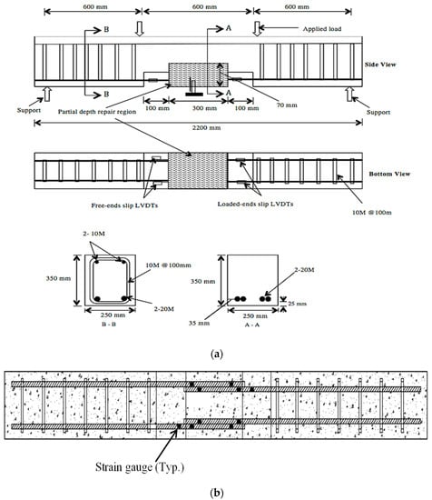
Figure 1.
(a) The cross section and reinforcement details of the lap splice beam; (b) Strain gauge layout.
Six lap splice beams were unconfined and six were wrapped with carbon fiber reinforced polymer (CFRP) sheets. For the wrapped condition, the CFRP sheet was U-wrapped in a single layer of 950 mm length and 300 mm width to confine the lap splice zone. For each confinement case, three beams were monolithic at different mass loss levels (control, 7.5% and 15% mass loss) and three beams were repaired with a partial depth repair concrete at different mass loss levels (control, 7.5% and 15% mass loss).
For the beams that were repaired with a partial depth repair, a pocket was designed for the repair purposes, with dimensions of 300 mm in length, 250 mm in width and 70 mm in depth. The concrete cover for all beams was 25 mm. A 25 mm clearance was kept under the spliced bars to meet the minimum clearance reinforcement of 19 mm or 6 mm larger than maximum coarse aggregate size in the partial depth repair material in accordance with the specification of ACI 364-2014.
All the beams were fabricated with two notches with dimensions of 100 mm × 50 mm at the bottom of the beam that exposed the flexural reinforcing bars. The two notches were placed at the two ends of the lap splice region to evaluate the bond stress-slip behavior. Five linear variable differential transformers (LVDTs) were used, two to measure the loaded end slip, two to measure the free end slip and one to measure the deflection of the beam, as revealed in Figure 1b.
A total of 10 electrical resistance strain gauges were used on the spliced bars for each beam to measure the strain distribution along the spliced length. Two strain gauges were fixed on each bar at the lap splice zone at distances of 50 mm and 225 mm from the beginning of the splice zone. Moreover, one strain gauge was placed on each side of the splice zone on the exposed reinforcing bar at the notches to measure the bar stress in this region where the tensile force was taken only by the bar in the beams. The increase in stress at other strain gauge locations toward the stress measured at this location as a test was used to describe the progress of the bar debonding.
2.2. Test Procedure
All of the lap splice beams were supported with a 1800 mm span length and tested statically under four-point loading until failure. The load was applied to the beam through a steel spreader beam connected to the actuator. The steel beam then transferred the load to two locations on the top of the beam to produce a constant moment in the central region of the lap splice beams. The test frame was servo-controlled with a capacity of 500 kN, and was run in displacement control at the rate of 0.3 mm/min. The displacement at the center of the lap splice beam was recorded as the load was applied until the failure occurred. Figure 2 shows the lap splice beam installed in the test frame.
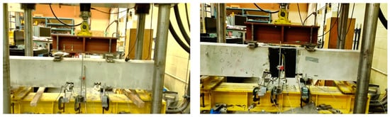
Figure 2.
Lap splice beam installed in the test frame.
2.3. Specimen Fabrication
The lap spliced bars that needed to be corroded were cast first into small concrete prisms with dimensions of 100 mm in depth, 100 mm in width and 300 mm in length, which was the lap splice length. To accelerate the corrosion rate, the concrete mix used to cast those prisms contained 3.8% salt of the cement mass, which was equivalent to 2.3% chloride. The prisms were kept in a special chamber subject to a continuous combination of oxygen and moisture, which is essential to facilitate the corrosion operation. Power supplies were used to accelerate the corrosion through an impressed current. The prisms were divided into two groups: 7.5% and 15% mass loss, and each group that was to be corroded to the same level was connected in series to ensure a constant current. Every prism was cast with one reinforcing bar (anode) and one stainless steel bar (cathode). To reach the desired corrosion level (7.5% or 15% mass loss), the period of accelerated corrosion was estimated using Faraday’s law [20]:
where mi is the mass loss (g); M is the atomic weight of the metal = 56 g for Fe; I is the corrosion current (A) = i × sa; i is the corrosion current density (μA/cm2); sa is the surface area of the corroded steel (cm2); T is the time (s); z is the valence of the corroding metal (2 for iron); F is Faraday’s constant = 96,500 A·s.
From Faraday’s law, the estimated time to achieve 7.5% and 15% mass loss was 75 and 150 days, respectively. Once the desired level of corrosion was achieved, the prisms were cut, and the reinforcing bars were removed and cleaned by sandblasting. Subsequently, the bars were weighed, and the mass loss of each bar was calculated as follows:
Consequently, the lap splice beams were fabricated and divided into two groups: monolithic lap splice beams and repaired lap splice beams. For the monolithic lap splice beams, the reinforcing bars were placed and cast with ready mix concrete. However, for the lap splice beams to be repaired with partial depth repair, the splice zone was isolated with high-density foam to form the pocket of the partial depth repair region. After curing, the high-density foam was removed, and the partial depth repair concrete was installed.
2.4. Material Properties
The partial depth repair material of SCC was used and extended with 50% of 13 mm coarse aggregate. Table 1 shows the proportions for the monolithic concrete. Table 2 shows the hardened properties such as compressive strength, splitting strength and fracture energy of the monolithic concrete (M) and self-consolidating concrete (SCC).

Table 1.
Mixture properties design for the monolithic concrete.
Table 2.
Hardened properties of monolithic concrete (M) and self-consolidating concrete (SCC).
The 20 M deformed reinforcing bar had a 479 MPa yield strength and 612 MPa ultimate tensile strength, and the supplier provided this data. The repair material had a rapid strength gain, a fast turnover of repair area and a flowable consistency. The CFRP wrapping sheet was SikaWrap Hex 103C with a weight of 610 g/m2. Two types of epoxies were used for the CFRP sheets installation: Sikadur 330 and Sikadur 300. Prior to placing the CFRP, the surface of the concrete was sealed with Sikadur 330, and the CFRP sheets were then saturated manually with Sikadur 300. The properties of CFRP sheets and the two epoxies are shown in Table 3 and Table 4, respectively.
Table 3.
Properties of carbon fiber reinforced polymer (CFRP) sheets.
Table 4.
Properties of epoxies.
3. Results and Discussion
3.1. Mode of Failure and Cracking Pattern
All of the lap splice beams failed by splitting bond failure (as intended). The first flexural crack in the beams occurred at the upper corners of the notches at the end of the lap spliced region, still within the constant moment region. As the applied load increased, more flexural cracks developed in the spliced zone together with longitudinal cracks along the lap spliced bars. It can be seen from Figure 3a that the longitudinal splitting cracks were developed on the bottom face of the beams from both ends of the splice regions. The unconfined beams had a sudden brittle failure associated with a loud sound resulting from the splitting of the final length of the concrete cover. The bottom face cracks in the unconfined beams formed a V shape (Figure 3b). Sizable chunks of concrete were formed and in some cases spalled off from the concrete cover at failure because of the absence of confinement.
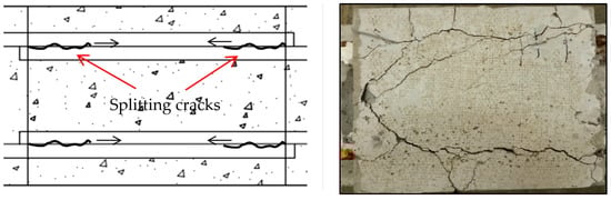
Figure 3.
(a) Initiation of splitting cracks on the bottom face of the beam. (b) Bottom face bond splitting cracks for an unconfined beam.
The mode of failure was different for the unconfined beams than for the beams confined with FRP sheets. The confined beams had a more ductile mode of failure related to the unconfined beams in which the confinement delayed the splitting of the concrete cover. Unlike the unconfined beams, the concrete cover did not spall off in the beams confined with the FRP sheet. The FRP sheets arrested the concrete cover in place after splitting occurred. The confined beams experienced an increase in their ultimate load, corresponding deflection at failure and flexural crack width compared to the unconfined beams. For the beams confined with the FRP sheet, the crack pattern could not be monitored during testing since the cracks did not penetrate the FRP sheet. At failure, the unconfined beam formed horizontal splitting cracks on the side of the spliced zone along the lap spliced bars. After the test, when the FRP sheets were removed for inspection, it was found that the failure produced smaller pieces of concrete compared to unconfined beams, as illustrated in Figure 4.
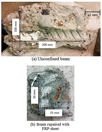
Figure 4.
Pieces of concrete of (a) unconfined beam, (b) beam confined with fiber-reinforced polymer (FRP) sheet.
3.2. Lap Splice Beam
Table 5 shows a summary of all lap splice beam test results, including the load at failure, the average bond strength at failure, the loaded end slip and the failure mode. The lap splice beams were labeled as follows: the first part (LS) refers to a lap splice and the second part refers to the type of concrete for monolithic concrete (M) and SCC for commercial prepackaged self-consolidating concrete extended with 50% of 13 mm coarse aggregate. The third part refers to the confinement condition (UN for the unconfined beams and F for the beams confined with FRP sheets). The last part represents the corrosion level (C for the control specimens (non-corroded), 7.5 for the specimens with a 7.5% mass loss level and 15 for the specimens with a 15% mass loss level). The splice length and the concrete cover for all beams were fixed as 300 mm and 25 mm, respectively.
Table 5.
Summary of lap splice beams test results.
Based on the splice length, the concrete cover, the mass loss level and the confinement condition, all lap splice beams were designed to fail by a splitting failure. The average bond strength was calculated using Equation (3).
where τb is the average bond strength (MPa); db is the bar diameter account for actual mass loss (mm); fs is the steel stress at failure (MPa); and Ls is the splice length (mm) = 300 mm.
3.3. Effect of Partial Depth Repair with and without FRP Wrapping
The load-deflection curves for the lap splice beams (monolithic specimens (M) and partial depth repaired specimens (SCC) with and without FRP wrapping (F)) are revealed in Figure 5a–c for the control beam sample and the 7.5% rebar mass loss and 15% rebar mass loss beams, respectively. The beams confined with FRP sheets experienced an increase in the ultimate load and the corresponding deflection at failure compared to the unconfined beams. Moreover, the maximum load and corresponding deflection were recorded for the beams wrapped with FRP sheets by 55% and 191%, respectively.
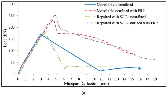
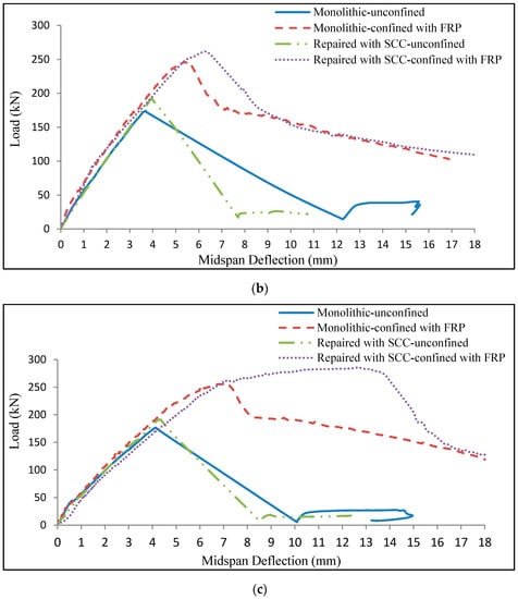
Figure 5.
Load deflection curves of monolithic beams and beams repaired with partial depth repair self-consolidating concrete (SCC) with and without FRP confinement. (a) Control beams; (b) beams with 7.5% mass loss; (c) beams with 15% mass loss.
The load-deflection curves increased linearly after initial flexural cracking until the maximum load was achieved in coincidence with bond splitting failure. After the splitting failure, the load-deflection behavior of the unconfined beams was different from the beams confined with FRP sheets. The splitting failure of unconfined beams was accompanied by a sudden drop in the applied load and rise in deflection. Nevertheless, the beams confined with FRP sheets revealed a ductile post-failure behavior, in which the load dropped gradually as the deflection increased. This could be attributed to the FRP sheets limiting the bond crack widths and preventing spalling of the concrete cover. Besides, the partial depth repair was able to restore and increase the capacity of the repaired beams, which had a higher maximum load at failure than that of the monolithic beams.
The LS-SCC-15-F beam failed by bar yielding followed by a splitting failure. It was observed that the stress on the bar exceeded the manufactured reported yield strength of 479 MPa before the splitting failure occurred. After the bar yielded, the deflection of the beam increased with a slight rise in the applied load before failure occurred. Except for this beam, all the other beams failed by splitting bond failure. The re-bond state (constant or slight increase in bond after failure) in the unconfined beams could be from the residual friction between the reinforcing bar and the surrounding concrete where the concrete keys did not shear off, unlike the confined beams. It was also observed that beams confined with FRC sheets sustained a higher load than unconfined beams. The higher yield strength of confined beams could be attributed to the existence of FRP sheets, which prevented the sudden failure of the beams and therefore, sustained higher loads.
3.4. Effect of Corrosion on Load-Deflection Response
Figure 6 shows typical load-deflection curves of beams with different levels of mass loss. The beams in the same mass loss category had almost the same stiffness. However, the stiffness decreased slightly with increased reinforcing bar mass loss. As the bar mass loss increased, the total cross-sectional area of the bars decreased, reducing the effective stiffness of the beam, thereby increasing the mid-span deflection. Despite the minor differences in load at failure, the average bond strength increased as the mass loss increased, as shown in Figure 7 due to improved bond strength between the concrete and reinforced bars. This occurred because as corrosion increased, the rebar surface became rougher, which improved both the mechanical bonds and friction properties.
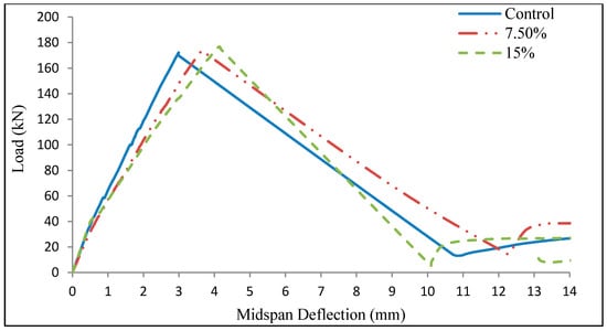
Figure 6.
Typical load deflection curve of monolithic unconfined lap splice beams with different levels of mass loss.
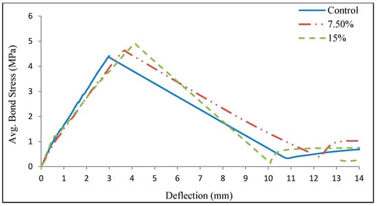
Figure 7.
Typical average bond stress versus deflection curve of monolithic unconfined lap splice beams with different levels of mass loss.
3.5. Bond Stress versus Slip Response
The typical bond stress versus slip response for the control monolithic beams (M) and partial depth repaired specimens (SCC) with and without FRP wrapping (F) is shown in Figure 8a. The beams confined with FRP sheets had higher values of bond strength and slipped at maximum load than the unconfined beams. The confined beams experienced a later start and slower growth of splitting cracks. The beams confined with FRP sheets revealed a rise in the bond strength values and the equivalent slip values by about 34–49%, and 56–260% compared to the unconfined beams, respectively. Regardless of the condition of confinement, the partial depth repair with the SCC had a higher bond strength than the monolithic specimens.
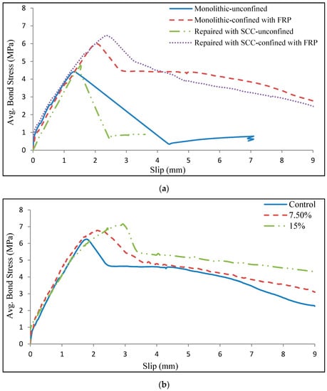
Figure 8.
(a) Average bond stress versus slip for control unconfined beams and beams wrapped with FRP. (b) Average bond stress versus slip for beams wrapped with FRP with different rebar mass loss.
The typical bond stress-slip curve of beams confined with FRP sheets for the control beam and the 7.5% and 15% mass loss beams are shown in Figure 8b. The bond strength and the corresponding slip increased with increasing rebar mass loss. This is because the cross sectional area of the bars decreased with increasing corrosion levels; thus, the force on the bar at bond failure decreased more slowly than the area of the bar [30,31].
4. Conclusions
The following conclusions are drawn based on the findings of this study:
- All of the unconfined beams and the beams confined with FRP sheets failed because of splitting bond failure. However, the beams confined with FRP sheets had a more ductile failure than the unconfined beams. At failure, the lap splice beams confined with FRP sheets produced smaller chunks of concrete than those of the unconfined beams.
- The average bond strength increased with increasing bar mass loss level due to the decrease in the cross-sectional area of the rebar. Therefore, as the bar diameter decreases, the bond force at failure decreases more slowly than the decreasing bar area. Also, as the corrosion level increased, the cleaned rebar surface roughness increased, which probably increased the mechanical bond contribution. Repairing the beams with partial depth repair SCC concrete enhanced the average bond strength compared to the monolithic beams.
- The beams confined with FRP sheets had a delayed bond failure related to that of the unconfined beams. The beams wrapped with FRP sheets had a higher maximum load and corresponding deflection than the unwrapped beams by 49% and 191%, respectively.
- The beams confined with FRP sheets showed a rise in the bond strength and the equivalent slip by 34–49%, and 56–260% compared to the unconfined beams, respectively.
Author Contributions
Conceptualization, H.A., T.T.; data curation, H.A., and R.A.; formal analysis, H.A., R.A., H.M.; investigation, R.A. and H.M.; methodology, H.A. and R.A.; project administration, H.A.; resources, H.A. and R.A.; supervision, T.T.; validation, H.A. and R.A.; visualization, H.A. and R.A.; writing, original draft preparation, H.A. and H.M.; writing, review and editing, H.A., R.A. and H.M. All authors have read and agreed to the published version of the manuscript.
Funding
This research project was supported by the Deanship of Scientific Research at Prince Sattam bin Abdulaziz University (Saudi Arabia) under the research project No. 2020/01/16810.
Acknowledgments
The authors gratefully acknowledge the technical support received from the University of Waterloo and Universiti Teknologi Malaysia (UTM).
Conflicts of Interest
The authors declare no conflict of interest.
References
- Amaireh, L.; Al-Rousan, R.Z.; Ababneh, A.N.; Alhassan, M. Integration of CFRP strips as an internal shear reinforcement in reinforced concrete beams. Structures 2020, 23, 13–19. [Google Scholar] [CrossRef]
- Junaid, M.T.; Elbana, A.; Altoubat, S. Flexural response of geopolymer and fiber reinforced geopolymer concrete beams reinforced with GFRP bars and strengthened using CFRP sheets. Structures 2020, 24, 666–677. [Google Scholar] [CrossRef]
- Al-Majidi, M.H.; Lampropoulos, A.P.; Cundy, A.B.; Tsioulou, O.T.; Alrekabi, S. Flexural performance of reinforced concrete beams strengthened with fibre reinforced geopolymer concrete under accelerated corrosion. Structures 2019, 19, 394–410. [Google Scholar] [CrossRef]
- Barris, C.; Sala, P.; Gómez, J.; Torres, L. Flexural behaviour of FRP reinforced concrete beams strengthened with NSM CFRP strips. Compos. Struct. 2020, 241, 112059. [Google Scholar] [CrossRef]
- Hadhood, A.; Agamy, M.H.; Abdelsalam, M.M.; Mohamed, H.M.; El-Sayed, T.A. Shear strengthening of hybrid externally-bonded mechanically-fastened concrete beams using short CFRP strips: Experiments and theoretical evaluation. Eng. Struct. 2019, 201, 109795. [Google Scholar] [CrossRef]
- Zuo, J.; Darwin, D. Splice Strength of Conventional and High Relative Rib Area Bars in Normal and High-strength Concrete. Struct. J. 2000, 97, 630–641. [Google Scholar]
- Azizinamini, A.; Pavel, R.; Hatfield, E.; Ghosh, S. Behavior of lap-spliced reinforcing bars embedded in high strength concrete. Struct. J. 1999, 96, 826–835. [Google Scholar]
- Hamad, B.S.; Najjar, S.S. Evaluation of the Role of Transverse Reinforcement in Confining Tension Lap Splices in High Strength Concrete. Mater. Struct. 2002, 35, 219–228. [Google Scholar] [CrossRef]
- Karataş, M.A.; Gökkaya, H. A review on machinability of carbon fiber reinforced polymer (CFRP) and glass fiber reinforced polymer (GFRP) composite materials. Def. Technol. 2018, 14, 318–326. [Google Scholar] [CrossRef]
- Wang, Z.; Almeida Jr, J.H.S.; St-Pierre, L.; Wang, Z.; Castro, S.G. Reliability-based buckling optimization with an accelerated Kriging metamodel for filament-wound variable angle tow composite cylinders. Compos. Struct. 2020, 254, 112821. [Google Scholar] [CrossRef]
- Masoud, S.; Soudki, K.; Topper, T. Postrepair Fatigue Performance of FRP-Repaired Corroded RC Beams: Experimental and Analytical Investigation. ASCE J. Compos. Constr. 2005, 9, 441–449. [Google Scholar] [CrossRef]
- Mohammadhosseini, H.; Yatim, J.M.; Sam, A.R.M.; Awal, A.A. Durability performance of green concrete composites containing waste carpet fibers and palm oil fuel ash. J. Clean. Prod. 2017, 144, 448–458. [Google Scholar] [CrossRef]
- Almusallam, A.; Al-Gahtani, A.; Aziz Rasheeduzzafar, A. Effect of Reinforcement Corrosion on Bond Strength. Constr. Build. Mater. 1996, 10, 123–129. [Google Scholar] [CrossRef]
- Alrshoudi, F.; Mohammadhosseini, H.; Alyousef, R.; Alabduljabbar, H.; Mustafa Mohamed, A. The Impact Resistance and Deformation Performance of Novel Pre-Packed Aggregate Concrete Reinforced with Waste Polypropylene Fibres. Crystals 2020, 10, 788. [Google Scholar] [CrossRef]
- Alyousef, R.; Mohammadhosseini, H.; Alrshoudi, F.; Alabduljabbar, H.; Mohamed, A.M. Enhanced Performance of Concrete Composites Comprising Waste Metalised Polypropylene Fibres Exposed to Aggressive Environments. Crystals 2020, 10, 696. [Google Scholar] [CrossRef]
- El Maadawi, T.; Soudki, K. Carbon-Fibre-Reinforced Polymer Repair to Extend Service Life of Corroded Reinforced Concrete Beams. J. Compos. Constr. ASCE 2005, 9, 187–194. [Google Scholar] [CrossRef]
- Okada, K.; Kobayashi, I.K.; Miyagawa, T. Influence of Longitudinal Cracking Due to Reinforcement Corrosion on Characteristics of Reinforced Concrete Members. Struct. J. 1988, 85, 134–140. [Google Scholar]
- Tahir, M.M.; Mohammadhosseini, H.; Ngian, S.P.; Effendi, M.K. I-beam to square hollow column blind bolted moment connection: Experimental and numerical study. J. Constr. St. Rese. 2018, 148, 383–398. [Google Scholar] [CrossRef]
- Cabrera, J.G. Deterioration of Concrete Due to Reinforcement Steel Corrosion. Cem. Concr. Compos. 1996, 18, 47–59. [Google Scholar] [CrossRef]
- ACI (American Concrete Institute). Protection of Metals in Concrete against Corrosion; ACI 222-01: Farmington Hills, MI, USA, 2001. [Google Scholar]
- ACI (American Concrete Institute). Guide for the Design and Construction of Externally Bonded FRP Systems for Strengthening Concrete Structures; ACI 440.2R-08: Farmington Hills, MI, USA, 2008. [Google Scholar]
- Garcia, R.; Helal, Y.; Pilakoutas, K.; Guadagnini, M. Bond Strength of Short Lap Splices in RC Beams Confined with Steel Stirrups or External CFRP. Mater. Struct. 2015, 48, 277–293. [Google Scholar] [CrossRef]
- Alyousef, R.; Topper, T.; Al-Mayah, A. Effect of FRP Wrapping on Fatigue Bond Behavior of Spliced Concrete Beams. J. Compos. Constr. 2015, 20, 04015030. [Google Scholar] [CrossRef]
- 24. Shihata, Ayman. 2011CFRP Strengthening of RC Beams with Corroded Lap Spliced Steel Bars. Master’s Thesis, University of Waterloo, Waterloo, ON, Canada, 2011.
- Almeida, J.H.S.; Souza, S.D.; Botelho, E.C.; Amico, S.C. Carbon fiber-reinforced epoxy filament-wound composite laminates exposed to hygrothermal conditioning. J. Mater. Sci. 2016, 51, 4697–4708. [Google Scholar] [CrossRef]
- Antunes, M.B.; Almeida, J.H.S., Jr.; Amico, S.C. Curing and seawater aging effects on mechanical, thermal, and physical properties of glass/epoxy filament wound composite cylinders. Compos. Commun. 2020, 22, 100517. [Google Scholar] [CrossRef]
- Malumbela, G.; Alexander, M.; Moyo, P. Serviceability of Corrosion-Affected RC Beams after Patch Repairs and FRPs under Load. Mater. Struct. 2011, 44, 331–349. [Google Scholar] [CrossRef]
- Emberson, N.K.; Mays, G.C. Significance of Property Mismatch in the Patch Repair of Structural Concrete. Part 3: Reinforced concrete members in flexure. Mag. Concr. Res. 1996, 48, 45–57. [Google Scholar] [CrossRef]
- Fang, C.; Lundgren, K.; Chen, L.; Zhu, C. Corrosion Influence on Bond in Reinforced Concrete. Cem. Concr. Res. 2004, 34, 2159–2167. [Google Scholar] [CrossRef]
- ACI (American Concrete Institute). Bond and Development of Straight Reinforcing Bars in Tension; ACI 408R-03: Farmington Hills, MI, USA, 2003. [Google Scholar]
- Alrshoudi, F.; Mohammadhosseini, H.; Tahir, M.M.; Alyousef, R.; Alghamdi, H.; Alharbi, Y.R.; Alsaif, A. Sustainable use of waste polypropylene fibers and palm oil fuel ash in the production of novel prepacked aggregate fiber-reinforced concrete. Sustainability 2020, 12, 4871. [Google Scholar] [CrossRef]
Publisher’s Note: MDPI stays neutral with regard to jurisdictional claims in published maps and institutional affiliations. |
© 2020 by the authors. Licensee MDPI, Basel, Switzerland. This article is an open access article distributed under the terms and conditions of the Creative Commons Attribution (CC BY) license (http://creativecommons.org/licenses/by/4.0/).