Article

An Investigation of the Mechanical and Physical Characteristics of Cement Paste Incorporating Different Air Entraining Agents using X-ray Micro-Computed Tomography

1
Building Materials and Construction Chemistry, Technische Universität Berlin, Gustav-Meyer-Allee 25, 13355 Berlin, Germany
2
Structural Engineering Department, Mansoura University, Elgomhouria St., Mansoura City 35516, Egypt
3
Department of Civil and Environmental Engineering, Sejong University, 209 Neungdong-ro, Gwangjin-gu, Seoul 05006, Korea
4
Faculty of Civil Engineering and Architecture, West Pomeranian University of Technology, Szczecin, Al. Piastow 50, 70-311 Szczecin, Poland
5
School of Natural and Built Environments, University of South Australia, Mawson Lakes Blvd, Mawson Lakes SA 5095, Australia
*
Author to whom correspondence should be addressed.
Crystals 2020, 10(1), 23; https://doi.org/10.3390/cryst10010023
Submission received: 13 December 2019 / Revised: 2 January 2020 / Accepted: 4 January 2020 / Published: 6 January 2020

Abstract

:
Improving the thermal insulation properties of cement-based materials is the key to reducing energy loss and consumption in buildings. Lightweight cement-based composites can be used efficiently for this purpose, as a structural material with load bearing ability or as a non-structural one for thermal insulation. In this research, lightweight cement pastes containing fly ash and cement were prepared and tested. In these mixes, three different techniques for producing air voids inside the cement paste were used through the incorporation of aluminum powder (AL), air entraining agent (AA), and hollow microspheres (AS). Several experiments were carried out in order to examine the structural and physical characteristics of the cement composites, including dry density, compressive strength, porosity and absorption. A Hot Disk device was used to evaluate the thermal conductivity of different cement composites. In addition, X-ray micro-computed tomography (micro-CT) was adopted to investigate the microstructure of the air-entrained cement pastes and the spatial distribution of the voids inside pastes without destroying the specimens. The experimental results obtained showed that AS specimens with admixture of hollow microspheres can improve the compressive strength of cement composites compared to other air entraining admixtures at the same density level. It was also confirmed that the incorporation of aluminum powder creates large voids, which have a negative effect on specimens’ strength and absorption.

1. Introduction

Nowadays, rapid population growth and development have led to a significant increase in energy demand. However, fossil fuels-which are the main energy resource-are limited and subject to being depleted in the next few decades. In addition, their use has had a harmful impact on the environment. They are responsible for climate change and environmental pollution; fossil fuels are the primary resource for CO2 emission globally [1]. To cope with these challenges, it is imperative to make optimum use of the available energy resources and to reduce energy consumption as much as possible. In reference to thermal comport, buildings consume about 40% of global energy consumption and are consequently responsible for about one-third of global carbon emissions [2]. High efficiency energy utilization in buildings has therefore become a principle policy for many countries. Recently, there has been increasing interest in improving the thermal insulation of buildings in order to save energy and to reduce the environmental problem. In case of existing structures, this goal can be mostly achieved by insulating the already existing structures (e.g. masonry walls), which occurs mostly during the restoration period [3]. However, for a purpose of erecting the new structures several insulating materials were developed for decreasing the energy losses from buildings and to meet structural stability and strength requirements. Lightweight cement-based materials are one of the most ideal materials for such applications, because of its high thermal insulation efficiency as well as its reasonable mechanical characteristics [4,5,6,7,8,9].
Today, lightweight concrete is available in a wide range of densities and strengths which makes it suitable for various applications. The basic advantages of lightweight concrete are its low thermal conductivity, which makes it ideal for energy conservation, as well as its low density, which reduces the dead load of structures. Cellular concrete is a type of lightweight concrete composed of cement, water, entrained air and sometimes fine aggregate [10,11,12]. Generally, two methods have been developed for entraining air in concrete; physically, with the use of pre-formed foam (foamed concrete) and chemically, through the use of an air-entraining agent (aerated concrete). Cellular concrete can be designed to have a density of 200 to 1800 kg/m3, depending on whether its applications are structural or non-structural [13]; though the density of cellular or lightweight concrete is relatively low, these materials have advantages to be used for both purposes. For example, structural lightweight concrete is largely used for building located in seismic area to reduce the mass subjected to seismic loads [14,15], and non-structural lightweight concrete is generally used for insulation and noise reduction [16,17].
Aerated concrete can be autoclaved (AAC) or non-autoclaved (NAAC) depending on the curing method used. In general, NAAC is known to be beneficial than AAC in the following aspects; NAAC is less expensive in production and shows better acoustic protection, fire safety, and better insulation than AAC [18,19,20]. On the basis of these advantages, between these approaches, the goal of the present research is to examine the properties of non-autoclaved aerated concrete, produced using different air-entraining agents (AEAs). NAAC is manufactured by creating macro porosity in a cement matrix, with the help of an expansive agent which reacts with the water and lime in the suspension [21]. This reaction liberates gas which expands the fresh concrete and generate pores, which reduce the weight and thermal conductivity of aerated concrete after hardening. The formed bubbles are nearly spherical [22] and have a diameter of about 10 µm to 1 mm [23] depending on the surfactant used. In addition to reducing the weight of concrete, air entraining agents are widely used to enhance concrete resistance to damage caused by freezing and thawing cycles. The type of air entraining agent has an important influence on the properties of aerated concrete [24,25]. Aluminum powder is normally used to obtain gas bubbles in concrete. In addition, various companies have developed different types of air entraining agents and foaming agents for normal and light-weight concretes.
To investigate the effect of different materials on aerated concrete, several researchers used various materials. Schackow et al. [26] used vermiculite and EPS to identify their effects on mechanical and thermal properties, and pre-saturated bentonite was adopted to produce ultra-lightweight concrete with numerous pores [27]. Super absorbent polymers (SAPs) was utilized as physical air entrainment in cement mortars [28]. Naratha et al. [29] have studied the effects of supplementary materials of the strength and thermal conductivity of non-autoclaved aerated concrete. Aluminum powder was added as a pore-forming agent in the amount of 0.2 wt.% of the binder content. A moderate-strength concrete, in the range of 13–23 MPa and with a density of about 1800 kg/m3, was developed. They reported that aerated concrete incorporating fly ash and silica fume has considerable advantages and low energy consumption, compared to autoclaved aerated concrete. In relation to this, Ramamurthy and Narayanan [30] have showed that fly ash plays a pivotal role in aerated concrete without deteriorating compressive strength. Aguilar et al. [31] have studied the microstructure of aerated cement pastes with fly ash, metakaolin and sepiolite additions; concluding that the addition of fly ash increases closed porosity and produces a higher amount of calcium silicate hydrates (C-S-H), as detected using differential thermal analysis (DTA) and scanning electron microscopy (SEM).
Several kinds of research have been carried out to investigate the influence of various parameters on the properties of aerated concrete. For instance, Narayanan and Ramamurthy [25] have reviewed the structure and properties of aerated concrete which is more homogeneous than normal concrete because of the absence of coarse aggregates. They classified the aerated concrete according to the pore formation method, the binder type and the curing method. They reported that curing and pore-formation methods are the main factors controlling the properties and microstructure of aerated concrete. On the other hand, Yang et al. [32] and Chen et al. [33] have claimed that the water to solid ratio is the most important factor in controlling the properties of aerated concrete. As the water to solid ratio increases, the density and (to a lesser extent) compressive strength decrease [34,35]. It has also been asserted that there is a linear relationship between aluminum powder content and concrete density, with density decreasing as aluminum content increases [25].
Lightweight concrete can be used for structural and non-structural purposes depending on its characteristics. EN 206 defines structural lightweight concrete as a material with dry density ranges between 800 and 2000 kg/m3 with a compressive strength higher than 13 MPa (LC12/13). Cement industry is one of the main parts for CO2 emissions worldwide. To produce sustainable cement-based materials and to reduce greenhouse gases, alternative cementitious materials need to be used to replace cement without harmful impacts on concrete properties. For this purpose, fly ash can be used as alternative material of cement with high replacement level. The research presented here aims to produce lightweight cement paste and evaluate its mechanical, physical and thermal properties, so as to provide the most effective material with good material properties. Hence, proposed material can be further applied as a base for lightweight concrete production. For this purpose, we produced a set of lightweight pastes with different additives, such as aluminum powder, an air entraining agent, and hollow microspheres. Their physical properties including density, absorption, compressive strength, and thermal conductivity were then evaluated and compared using sensitive measurement tools. To figure out the pore characteristics, which strongly affect material properties, X-ray micro-computed tomography (micro-CT) was adopted and utilized to visualize the pore distribution inside the specimens. Micro-CT is a nondestructive testing method that uses X-ray and can describe the inner structure of an object without damaging the specimen. For lightweight cementitious composites, micro-CT can be utilized to investigate the characteristics of microstructural features [36,37,38,39,40]. With the results obtained, the effectiveness of each additives in achieving better mechanical and thermal lightweight composites properties was compared.

2. Preparation of Specimens

2.1. Materials

Ordinary Portland cement CEM I 42.5 N provided by HeidelbergCement GmbH (Germany) and fly ash (EFA-Füller HP, Baumineral, Germany) were used in this investigation, conforming to EN 197-1 and EN 450-1, respectively. The physical properties and chemical composition of cement and fly ash were measured experimentally in the laboratory, as shown in Table 1. The cement: fly ash ratio was kept at 1:3 by mass, for all mixes. The water/binder ratio was constant for all the mixes (w/b = 0.50). The w/b ratio was selected to achieve a workable cement composite with slump flow ranges between 420–480 mm according to EN 13350-5.
Three methods were used to generate air voids inside the cement paste. The first was the chemical expansion method, using aluminum powder with 0.5, 1, 2, and 3 wt.% binder content. The second method involved adding a tenside-based air entraining agent, with the same ratios as in the case of the aluminum powder: 0.5, 1, 2, and 3 wt.%. The third method involved adding prefabricated hollow plastic air bubbles (microspheres), with 0.5, 1, 2, and 3 wt.% mass of binder. Hollow microspheres are materials with spherical voids inside a plastic shell, having a diameter of 25–60 mm (median: 35 mm) and a density of 0.2 g/cm3 [40]. Each method of creating artificial voids produces a different volume of air inside the paste. The dosage of the materials used for producing the air was therefore kept constant to investigate their effects on paste porosity.

2.2. Mix Proportions and Specimen Preparation

In this investigation, a total of thirteen cement pastes were prepared and produced (Table 2). Specimens with different additives were denoted as AA (air entraining agent), AL (aluminum powder), and AS (hollow microspheres), with the numbers after the specimen names presenting the amount of air entraining agent. To produce the specimens, a standard mortar mixer with 5 liter capacity and two mixing speed (140 rpm and 285 rpm according to EN 196-3) was used for mixing the components. After weighing the proportions of each material, fly ash and cement were firstly dry mixed for 1 min at the low speed, to ensure better distribution and homogeneity of the mixture. The water and air entraining agents were then added within thirty seconds and further mixed for 1 min at low speed. Consequently, there was a minute break to remove the cement paste adhering to the sides and the bottom of the bowl and to place it in the middle of the bowl. Finally, the mixer was run at high speed for 2 min. The mixing procedures for all the mixes were carried out in the same manner. Steel molds of 40 × 40 × 160 mm3 were used for manufacturing cement pastes. After casting, the specimens were covered with a plastic sheet and kept in chamber with controlled temperature and relative humidity of 21 ± 1 °C and 99%, respectively. After 24 h of casting, the samples were demolded. They were then cured under water at a temperature of 20 ± 1 °C. At the age of testing, the prisms were cut to small cubes 40 × 40 × 40 mm3. The samples were surface dried prior to undertaking compressive strength tests. The first mix was designed without any air entraining agent, having been designated as the reference mix.

3. Measurements of Characteristic Properties

3.1. Material Properties

3.1.1. Material Density

Dry density ( ρ d r y ) was determined according to EN 12390-7. After curing under water for 28 days, the submerged mass was measured (under water) to determine the actual volume of the samples. The saturated samples were then dried in an oven at 105 °C, to a constant mass. From the dry mass and volume obtained, the following formula was implemented to calculate the dry density (Equation (1)):
ρ d r y = m d r y / V
where mdry is the mass of the sample (kg) and V is the volume of the sample (m3).

3.1.2. Compressive Strength

For the compressive strength determination, samples with dimensions of 40 × 40 × 40 mm3 were used. The surface of the samples with aluminum powder was not smooth or homogeneous; therefore, the samples were polished before testing to remove lumps and indentations and to make their sides flat. A modern digital crushing machine (Zwick Roell, Berlin, Germany) was used for performing the compressive strength tests. Six cubes of each mix were tested, with the mean value taken under consideration in this investigation.

3.1.3. Thermal Properties

The thermal conductivity of the cement paste specimens was evaluated experimentally using a Hot Disk device (Hot Disk AB, Göteborg, Sweden) which meets the requirements of ISO 22007-2 [41]. In this method, two samples from the same mix were used, with the sensor laid between the samples. Before measuring, the samples were polished to make them flat to ensure that no gaps between the sensor and the surfaces of the samples. Subsequently, the samples were dried in an oven at a temperature of 105 ± 5 °C, until reaching a constant mass so as to remove moisture, which has a critical influence on the thermal properties of cement-based materials. The measurements were repeated three times for each sample at different places, with the mean value considered. More details about thermal property measurement using the Hot Disk can be found in [40].

3.1.4. Effective Water Porosity

The effective water porosity of the aerated cement pastes, being the accessible porosity by water, was measured using the simple method of water displacement. In this method, the sample must be saturated under water for at least 24 h. After measuring the wet mass, the submerged mass under water was determined. The saturation samples were then dried in an oven at 105 ± 5 °C, until constant mass. From the information of the mass in both dry (mdry) and saturated states (msat), and with the mass under water (munder), the effective water porosity (P) can be calculated with the following equation (Equation (2)) [42]:
P ( % ) = m s a t m d r y m s a t m u n d e r   × 100 %

3.1.5. Water Absorption

The water uptake capabilities of a partially immersed specimen can be measured according to ISO standard (15148). This method involves placing a dried specimen in a container of water, such that the immersion depth of the specimen is 5 mm. The primary force that pulls water up into the specimen is capillary suction. Increases in the specimen mass are determined at set time periods. Several measurements were taken over a period of up to 24 h, and a straight line was fitted to the plot of the increase in mass, versus the square root of time. From this relationship, it was possible to determine the absorption coefficient of the cement-based materials.

3.2. Microstructure Evaluation Using X-Ray Micro-Computed Tomography (Micro-CT)

X-ray micro-computed tomography (micro-CT), a nondestructive investigation method, was used to estimate the spatial distribution of pores within the cement-based materials. This technique allows a series of cross-sectional images and microstructures to be obtained. Detailed pore characteristics, such as pore size distribution and pore density contour, were also examined using micro-CT images and imaging tools [43]. More details about this method can be found in [39], with only a brief explanation of the CT imaging procedure presented in this paper. Figure 1 shows the imaging process used in this study. First, a region of interest (ROI) is selected from an original image for effective examination of the sample. The original and ROI images were 8-bit images, represented by a value ranging from 0 (black) to 255 (white) in grayscale. Each image was composed of 1000 × 1000 pixels with a 27.0 µm pixel size. A binary image for classifying solids and pores was then generated, using the Otsu method [44] and an appropriate threshold value. The 3D sample for describing the pore structure was generated by consequent stacking of a series of binary images. Using the 3D images of the specimens, material characteristics, such as porosity and the spatial distribution of pores, can be effectively examined.

4. Results and Discussions

4.1. Material Properties of the Specimens

In this section, several properties of specimens with different additives and dosages are presented and discussed. The methods in Section 3.1 were adopted for each property.

4.1.1. Density

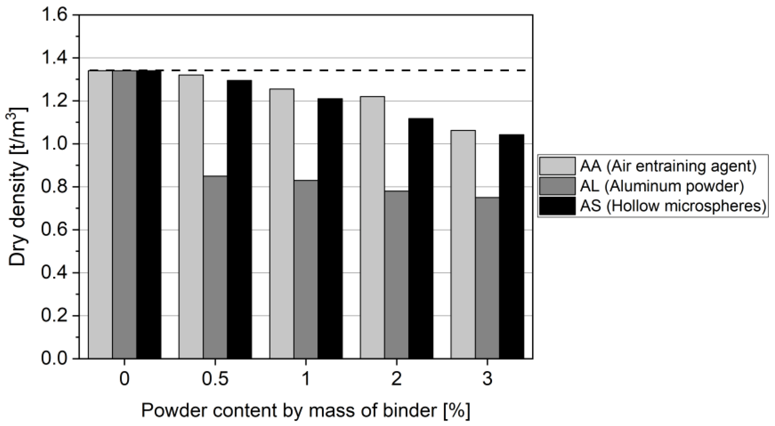
Figure 2 shows the experimental results of the dry density of cement composites. It can be clearly seen that in all cases, the density decreased as the amount of AA increased. Both AA and AS specimens showed similar effects on the density of the cement pastes; falling from 1.34 t/m3 (reference - A0) to 1.06 t/m3 and 1.04 t/m3. for mixes with 3 wt.% of AA and AS, respectively. However, the aluminum powder was much more effective than either AA or AS in reducing density. Using 0.5% AL reduced it from 1.34 to 0.85 t/m3. However, with a higher addition of AL, up to 3 wt.%, the density decreased only slightly more, to 0.75 t/m3, as can be seen for the results of the AL3 specimen.

4.1.2. Compressive Strength

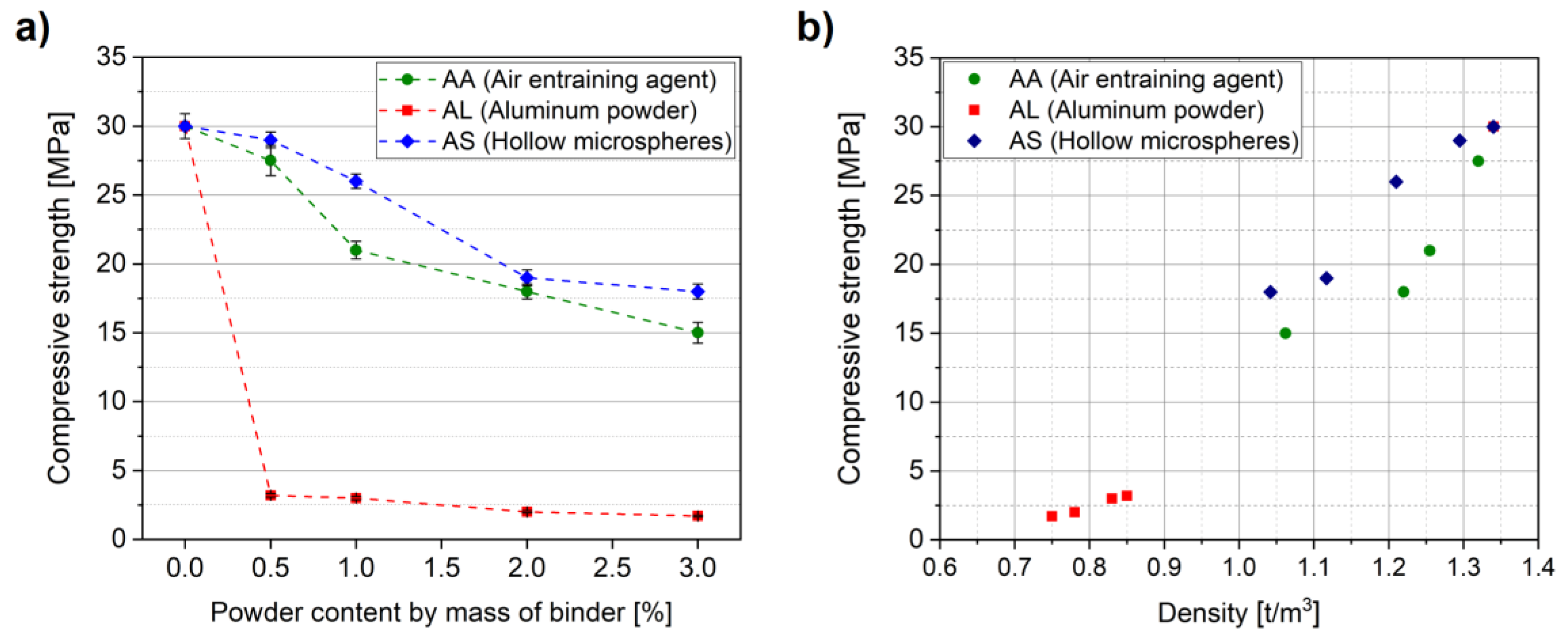
Compressive strength of concrete depends mainly on its major components; aggregate, cement paste, and transition zone in between. This study focuses on the properties of cement matrix which affect mechanical properties of cement-based materials significantly. Compressive strength of cement pastes was measured as an indicator of mechanical properties after curing for 28 days. Figure 3 shows the experimental results of the compression test on different pastes. In this figure, it is clearly presented that the incorporation of air voids into cement composites significantly decreases the compressive strength depending on the dosage and type of air entraining method. The AL specimens with aluminum powder show the lowest strength, which dropped from 30 MPa for reference mix without aluminum powder to 3.2 and 1.7 MPa for pastes with 0.5 and 3 wt.% aluminum powder, respectively. The same trend of the strength reduction with inclusion of air voids can be found in the case of the AA mixes, although the amount of the change is less. With the use of 3 wt.% of AA, the strength decreased to 18 MPa which represents about 60% of the reference mix. The influence of hollow microspheres (AS) on strength reduction is similar to that of the AA mixes. With addition of 3 wt.% of hollow microspheres, the compressive strength decreased to 15 MPa.
Moreover, it is obvious from the results that 0.5 wt.% of aluminum powder reduced the strength significantly. This indicates that aluminum powder is more effective in producing air voids even with small dosage which reduces the density as well as the compressive strength. The influences of the other methods, AA and AS, on density and strength are not significant than that of aluminum powder even with higher dosages, as can be seen in Figure 3a. The relationship between the strength and dry density of cement pastes is presented in Figure 3b. The experimental results confirm that dry density has clear relationship with the compressive strength of cement pastes. The strength deterioration in the samples is directly attributable to increases in porosity volume and reductions in the solid structure volume. The strength retrogression was more pronounced in the case of aluminum powder, which was not only related to an increase in porosity volume, but also to the large size of the pores created, as detected by micro-CT measurements, which are presented below.

4.1.3. Effective Water Porosity

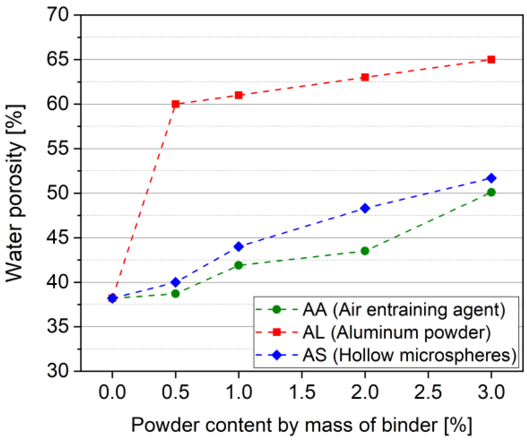
Water was used to evaluate cement paste porosity experimentally, using the water displacement method. Figure 4 illustrates the experimental results of total porosity at an age of 28 days. It can be seen that the reference mix (A0) had the lowest porosity of about 38 vol.%. For the other mixes, porosity increased with air content. With 3 wt.% AA, it increased to 50.1 vol.%; however, with 3 wt.% AS, it reached 51.7 vol.%. The increase in porosity was much higher in the mixes with aluminum powder. It increased from 38 vol.% without aluminum powder to 65 % with 3 wt.%. It is clear in the figure that the addition of 0.5 wt.% of aluminum powder increased the porosity to 60 vol.% which was more effective than 3 wt.% of AA or AS, where the porosity was about 50.1 vol.% and 51.7 vol.%, respectively. In addition, the experimental results indicate that higher dosages of aluminum powder do not significantly increase porosity in comparison to lower dosages; an increase in aluminum powder dosage from 0.5 wt.% to 3 wt.%, increased porosity from 60 to 65 vol.%. It can be seen from Figure 4 that increasing AA and AS dosages increased porosity gradually. However, in the case of AL, porosity increased primarily at the beginning, with the rate of increase obviously decreasing later with the increment in the AL content.

4.1.4. Water Absorption

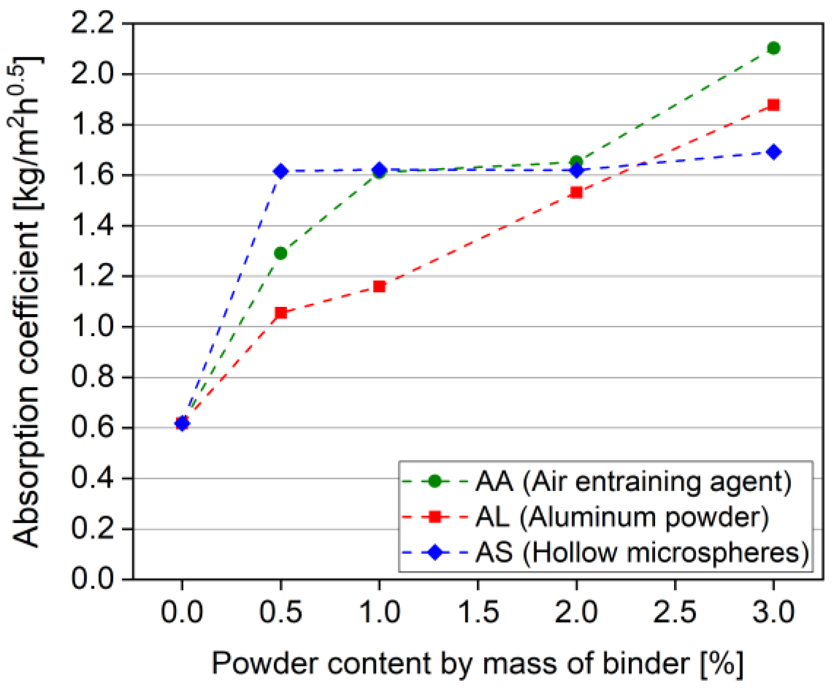
Figure 5 presents the water absorption coefficient values of the different cement pastes. Mix A0, without entrained air, had the lowest water absorption, of about 0.61844 kg/(m2·h0.5). However, mix AA3 with 3 wt.% AA had the highest water absorption coefficient, of about 2.10211 kg/(m2·h0.5). In contrast to the porosity results, mixes with the aluminum powder had a lower absorption than mixes with the AA. For mixes with the hollow microspheres (AS), the absorption was higher than in the control mix, though a marginal increase in absorption was observed with an increase in AS dosage. Compared to AA mixes, those with the AS had a lower absorption coefficient. The capillary suction force controls absorption rate and quantity, in the method used to measure water absorption (water uptake). As a result, pores in the capillary range are more effective in increasing the water absorption coefficient. In the case of aluminum powder, most of the pores were large in size, and as a result, the water absorption of these mixes was smaller than in the other mixes, where most of the pores were in the size range of the capillary pores. It is clear from the results that, the water absorption of composites made with hollow microspheres is increasing up to 0.5 wt.%. With increment of AS content no significant increase in the absorption can be detected. This can be attributed to the nature of microspheres which are closed pores with weak shell and cannot create a continuous passage for fluids to transfer. Most of these pores do not participate in increasing the water absorption as can be reflected from the experimental results and this can be considered as an advantage of this material compared to other air entraining materials.

4.1.5. Thermal Conductivity

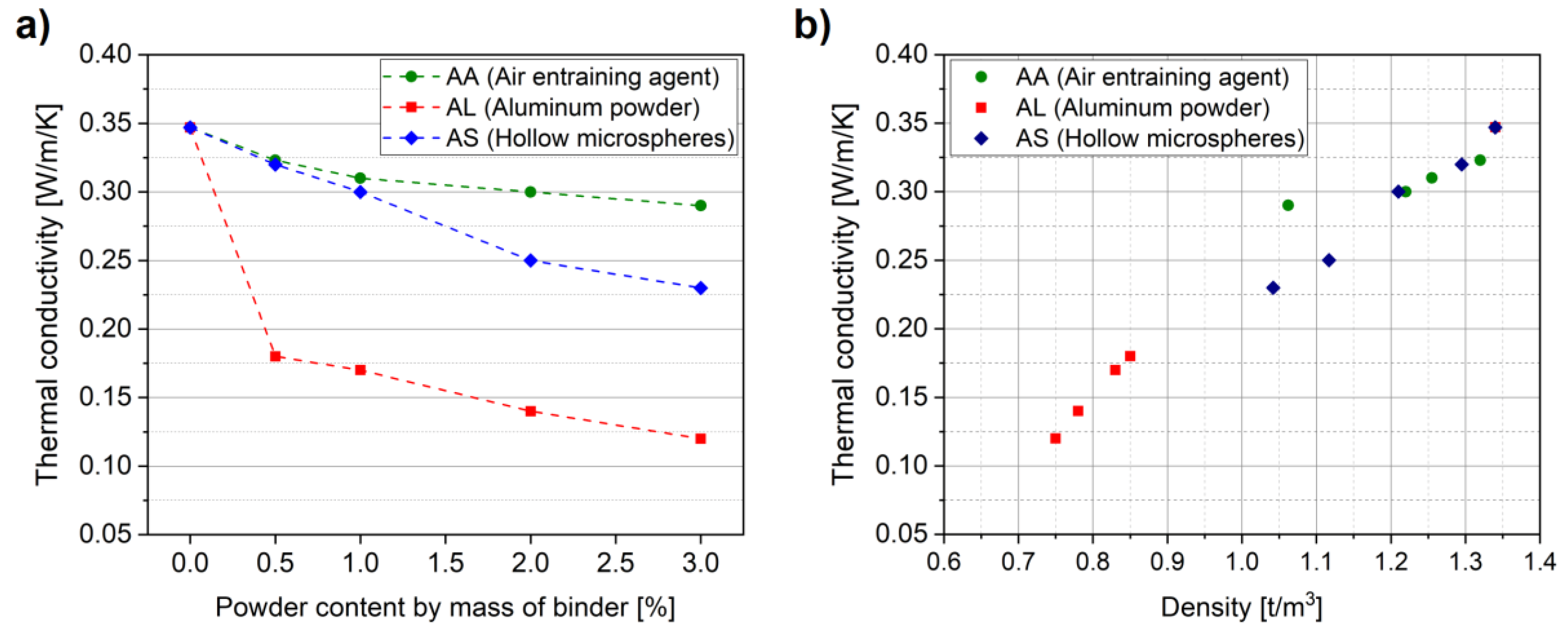
Figure 6 presents the experimental thermal conductivity results of the different cement paste samples. The thermal conductivity of the reference mix (A0) was about 0.347 W/(m·K). The thermal conductivity decreased as the AA content increased, reaching a value of 0.29 W/(m·K) at 3 wt.%. The experimental results for the mixes with hollow microspheres (AS) were similar to those with AA; conductivity fell from 0.32 W/(m·K) with 0.5 wt.% AS to 0.23 W/(m·K) with 3 wt.%. Aluminum powder seems to have a remarkable influence on thermal conductivity; with the addition of 0.5 wt.%, thermal conductivity dropped to 0.18 W/(m·K), while an addition of 3 wt.% aluminum powder reduced thermal conductivity to 0.12 W/(m·K).
Thermal conductivity is a material property related directly to dry density, as well as to the moisture content of the material. In this experiment, all of the samples were dried to a constant mass; as a result, the main factor influencing thermal conductivity was dry density [10]. Mixes with aluminum powder had the lowest thermal conductivity, due to reduced density as compared to other mixes, as can be seen in Figure 2 and Figure 6. Heat transfer in any materials depends on its components: solid structure and voids. With decreasing material density, pore volume increases, and the heat transfer decreases; this influence can be clearly detected from the results of thermal conductivity of cement pastes with different densities.

4.2. Pore Characteristics Using X-Ray CT

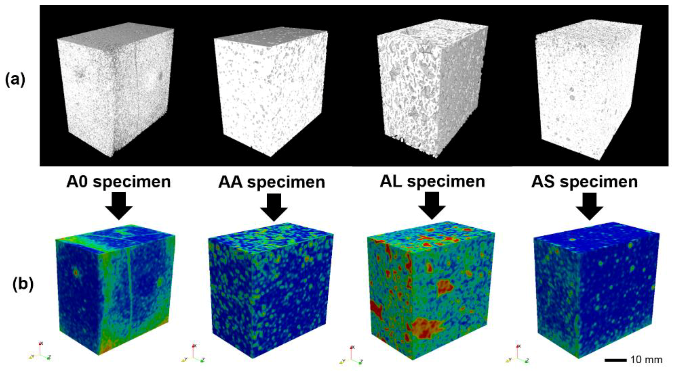
The inner structures of the cement pastes specimens with different admixtures were examined using X-ray CT images. Figure 7a shows the binarized 3D micro-CT images of A0, AA3, AL3, and AS3 specimens, which were obtained without damaging the specimens. In the binary figures, the white region represents the solid part of the specimen, while the black region inside the specimen presents the pores. From this figure, the pore structure inside each specimen can be easily identified. In Figure 7a, AA and AS specimens with air entraining agent and hollow microspheres solid, respectively, have a relatively high porosity as compared to the reference (A0) specimen, with their spatial distribution seemingly relatively uniform. However, the AL specimen with aluminum powder had distinctively larger pores and porosity than the other specimens; it denotes that aluminum powder had a more significant effect on securing the pores inside the specimens, than did the other admixtures.
For a more detailed investigation of the pore structures using the 3D images, porosity, spatial pore density, and pore size distribution were also examined qualitatively and quantitatively. The porosity of each specimen was calculated based on the number of pore voxels in the 3D images; the obtained total porosities of the specimens were 14.5 vol.% (A0), 22.3 vol.% (AA3), 35.1 vol.% (AL3), and 19.9 vol.% (AS3). The porosity computed from the micro-CT measurement was much smaller than that of the water porosity because of the resolution limit of the used images. Since pores even in the order of a few micrometers or even less can be detected using the experimental approach, micro-CT porosity only concerns an analysis of pores larger than the image resolution (27.0 µm); the difference thus results from the minimum measurable pore size of each method. Despite their limitations, micro-CT images can be used to visualize pore structures both quantitatively and qualitatively. From the porosities obtained, the effects of each admixture on material porosity can be examined. The AL3 specimen shows the largest porosity which causes low thermal conductivity and mechanical strength. In the same manner, the AS3 specimen with the lowest porosity among the cases shows the largest compressive strength in Figure 3; these results confirmed that the porosity data obtained from micro-CT presents consist result with the measured properties of the specimens.
The spatial distribution of the pores in the specimens have been clearly described in Figure 7b, where the pore density of each specimen has been represented in visual form. To calculate pore density, the local porosity of the specimen was calculated for the whole specimen, after which computed values were assigned for every voxel of the specimen. For example, in the figure for the AL3 specimen, the red region indicates a region with a high local porosity, while the blue one represents a region with low local porosity. From these contours, the spatial distribution of pores in each specimen can be identified. In general, the pore distribution in the AL3 specimen can be considered as relatively uniform, showing an anisotropic trend, because the larger pore density values are distributed in a specific region. A similar phenomenon has been observed by Shabbar et al. [45] where aerated concretes containing higher aluminum powder contents (less than 0.5 wt.%) exhibited more anisotropic voids. From the results, both general trend of pore clustering as well as the effect of air entraining agents on the pore characteristics of the materials.
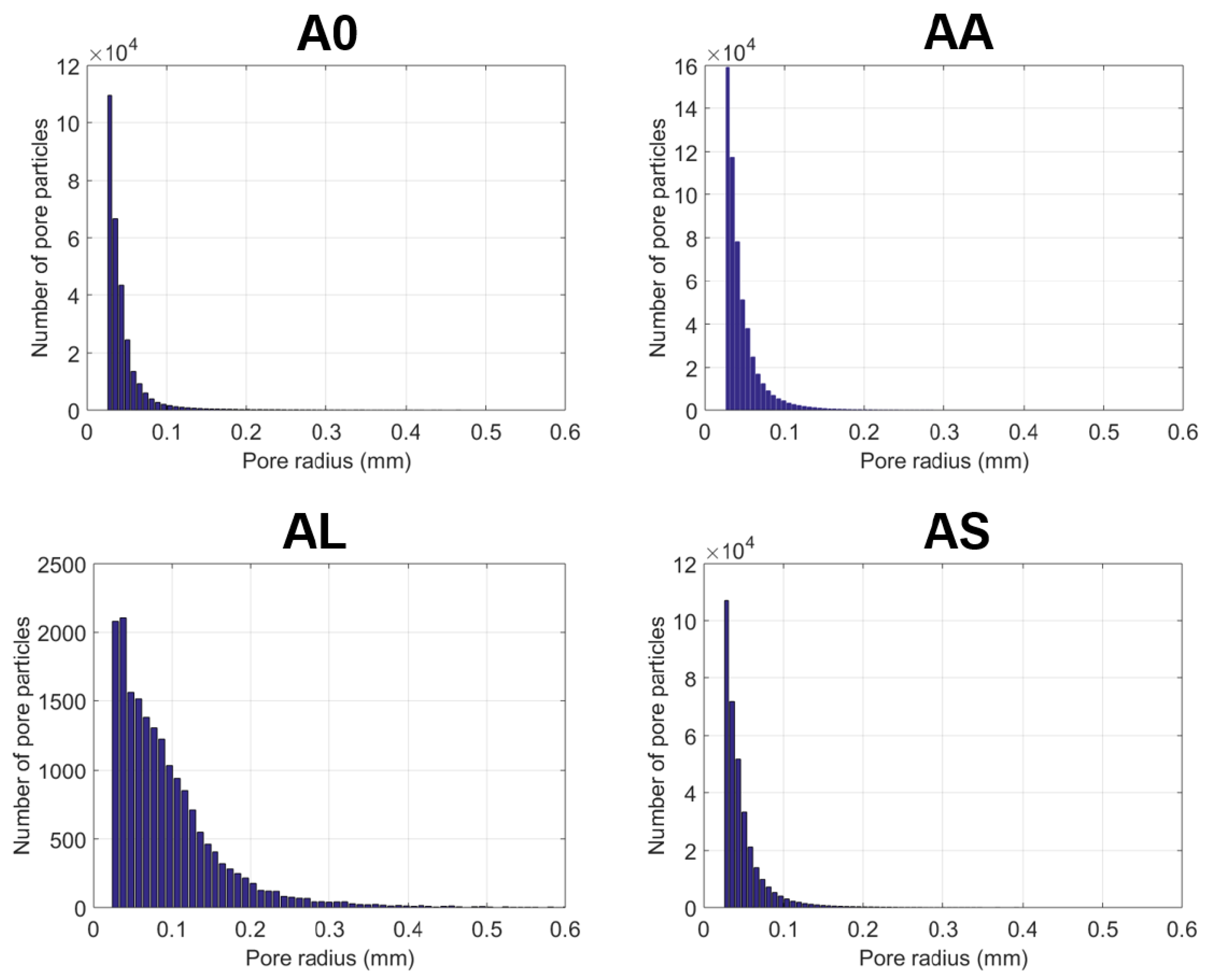
Figure 8 shows the pore size distribution in each specimen. From this figure, the relative pore sizes of the specimens can be compared, with all the specimens with air-entraining admixtures containing higher pore volume as well as pore sizes, particularly in the case of the AL3 specimen. It can therefore be confirmed that the pore distribution in the AL3 specimen was anisotropic, meaning that the use of aluminum powder in cement-based materials can induce a relatively large and anisotropic pore distribution. In addition, the data obtained shows consistent results in regard to other material properties. For example, the general trends regarding compressive strength and thermal conductivity, as shown in Figure 3 and Figure 6, are similar to the pore size distribution and porosity results in Figure 7 and Figure 8; both properties decreased as the amount of air-entraining agent or porosity increased. This result demonstrates that the use of micro-CT can be successfully utilized to describe the correlation between the material properties and the pore characteristics of cement-based materials.
Physical and chemical characteristics of fine materials affect the performance of air entraining agent (AA) as well as aluminum powder (AL) significantly, while their influence on hollow microsphere (AS) is very limited. The performance of AA and AL depends on the pH value of the pore solution and on the presence of other supplementary materials. The presence of fly ash influences the performance of AA negatively because the carbon particles in the fly ash absorb the agent and reduce their reactivity; consequently, higher dosages are needed. In addition, the carbon particles destabilize entrained air bubbles and change its volume in fresh status of cement-based materials [22]. In the case of aluminum powder, the alkali contents and cement fineness affect its performance significantly [46]. Other parameters, such as temperature, pH of the pore solution, and the consistency of the paste, influence the reactivity of aluminum powder [47]. In contrast, hollow microspheres are more stable and do not rely on the chemical composition of the used materials strongly. Only over-mixing for long period can destroy the voids and change their distribution. To avoid these problems in this investigation, cement and fly ash with a constant proportion of 1:3 was used for all mixes so that no influences can be occurred due to chemical composition. In addition, the mixing sequence and period were the kept the same for all mixes.

5. Conclusions

In this investigation, three different materials: aluminum powder (AL), air entraining agent (AA) and hollow microspheres (AS) were adopted to create pores inside cement pastes. The same amounts of each material were used to produce lightweight pastes with pores, with the effects of their dosage on material properties and characteristics investigated. The cement pastes’ physical and mechanical properties were measured experimentally. In addition, paste microstructures were characterized using micro-CT images. The remarks below serve as a conclusion:
  • An addition of aluminum powder increases air void contents more than other air-induced materials even with lower dosage. The addition of 0.5 wt.% of aluminum powder significantly reduces dry density, while higher dosages have negligible additional effects. The dry density of the specimens with air entraining agent and hollow microspheres are similar and reduced gradually with increasing the dosages.
  • Dry density and compressive strength of aluminum powder pastes are much lower than both air entraining agent and hollow microspheres.
  • Thermal conductivity is related directly to material density as reflected by the experimental results. Aluminum powder mixes had the lowest thermal conductivity, as compared to air entraining agent and hollow microspheres, with aluminum powder being the most effective for the purposes of insulation.
  • Mixes with hollow microspheres showed lower thermal conductivity than mixes with air entraining agent due to different in density as well as pore size distribution.
  • Among the used air entraining additives, the use of hollow microspheres is the most beneficial to achieve higher compressive strength. In contrast, aluminum powder can produce highly porous and large pores, as according to the micro-CT measurements. In particular, the use of aluminum powder can generate anisotropic pore clusters, which can cause a reduction in mechanical properties, while improving insulation.
As the results of this study have shown, each air-entraining agent has both advantages and disadvantages depending on thermal, mechanical, and absorption characteristics. The appropriate additive can therefore be selected according to the characteristics of the material at hand. In addition to the results of this study, the systematic investigation tools used here can be utilized in the further development of advanced lightweight cement-based materials as well as special building materials with particular objectives. In addition, the investigation of specimens with the same porosity but different air entraining agents can be conducted as a further study.

Author Contributions

Conceptualization, S.-Y.C. and M.A.E.; methodology, M.A.E. and M.E.E.M.; software, S.-Y.C.; validation, M.A.E., S-Y.C. and M.E.E.M.; formal analysis, M.A.E., S.-Y.C., and P.S.; investigation, M.A.E., M.E.E.M., S.M. and O.Y.; resources, P.S. and S.M.; data curation, S.-Y.C., M.A.E. and P.S.; writing—original draft preparation, M.A.E., S.-Y.C. and M.E.E.M.; writing—review and editing, S.-Y.C., M.A.E., P.S., O.Y. and S.M.; visualization, P.S. and S.-Y.C.; supervision, M.A.E. and M.E.E.M.; project administration, P.S. and M.A.E.; funding acquisition, P.S. and M.E.E.M. All authors have read and agreed to the published version of the manuscript.

Funding

This project has received funding from the European Union’s Horizon 2020 research and innovation program under the Marie Skłodowska-Curie grant agreement No. 841592.

Acknowledgments

This research is supported by the German Egyptian Mobility Program for Scientific Exchange and Excellence Development (GE-SEED). P.S. is supported by the Foundation for Polish Science (FNP). The authors would like to express their appreciation to Paul H. Kamm (Helmholtz Centre Berlin) for his assistance in micro-CT imaging.

Conflicts of Interest

The authors declare no conflict of interest.

References

  1. IEA. CO2 Emissions from Fuel Combustion Highlights; International Energy Agency: Paris, France, 2016. [Google Scholar]
  2. Tyagi, V.V.; Pandey, A.K.; Buddhi, D.; Kothari, R. Thermal performance assessment of encapsulated PCM based thermal management system to reduce peak energy demand in buildings. Energy Build. 2016, 117, 44–52. [Google Scholar] [CrossRef]
  3. Foraboschi, P. Effectiveness of novel methods to increase the FRP-masonry bond capacity. Comp. Part B Eng. 2016, 107, 214–232. [Google Scholar] [CrossRef]
  4. Chung, S.-Y.; Stephan, D.; Abd Elrahman, M.; Han, T.-S. Effects of anisotropic voids on thermal properties of insulating media investigated using 3D printed samples. Constr. Build. Mater. 2016, 111, 529–542. [Google Scholar] [CrossRef]
  5. Chung, S.-Y.; Abd Elrahman, M.; Stephan, D.; Kamm, P.H. The influence of different concrete additions on the properties of lightweight concrete evaluated using experimental and numerical approaches. Constr. Build. Mater. 2018, 189, 314–322. [Google Scholar] [CrossRef] [Green Version]
  6. Garbalińska, H.; Strzałkowski, J. Thermal and strength properties of lightweight concretes with variable porosity structures. J. Mater. Civ. Eng. 2018, 30, 04018326. [Google Scholar] [CrossRef] [Green Version]
  7. Sadowski, Ł.; Popek, M.; Czarnecki, S.; Mathia, T.G. Morphogenesis in solidification phases of lightweight concrete surface at early ages. Constr. Build. Mater. 2017, 148, 96–103. [Google Scholar] [CrossRef]
  8. Kurpinska, M.; Kułak, L. Predicting Performance of Lightweight Concrete with Granulated Expanded Glass and Ash Aggregate by Means of Using Artificial Neural Networks. Materials 2019, 12, 2002. [Google Scholar] [CrossRef] [Green Version]
  9. Foraboschi, P. Masonry does not limit itself to only one structural material: Interlocked masonry versus cohesive masonry. J. Build. Eng. 2019, 26, 100831. [Google Scholar] [CrossRef]
  10. Dorey, R.; Yeomans, J.; Smith, P. Effect of pore clustering on the mechanical properties of ceramics. J. Eur. Ceram. Soc. 2002, 22, 403–409. [Google Scholar] [CrossRef]
  11. Amran, Y.H.; Farzadnia, N.; Ali, A.A. Properties and applications of foamed concrete; a review. Constr. Build. Mater. 2015, 101, 990–1005. [Google Scholar] [CrossRef]
  12. Jaing, J.; Lu, Z.; Niu, Y.; Li, J.; Zhang, Y. Study on the preparation and properties of high-porosity foamed concretes based on ordinary portland cement. Mater. Des. 2016, 92, 949–959. [Google Scholar] [CrossRef]
  13. Chung, S.-Y.; Lehmann, C.; Abd Elrahman, M.; Stephan, D. Pore characteristics and their effects on the material properties of foamed concrete evaluated using micro-CT images and numerical approaches. Appl. Sci. 2017, 7, 550. [Google Scholar] [CrossRef] [Green Version]
  14. Foraboschi, P. Bending load-carrying capacity of reinforced concrete beams subjected to premature failure. Materials 2019, 12, 3085. [Google Scholar] [CrossRef] [PubMed] [Green Version]
  15. Foraboschi, P. Structural layout that takes full advantage of the capabilities and opportunities afforded by two-way RC floors, coupled with the selection of the best technique, to avoid serviceability failures. Eng. Fail. Anal. 2016, 70, 387–418. [Google Scholar] [CrossRef]
  16. Abd Elrahman, M.; Chung, S.-Y.; Sikora, P.; Rucinska, T.; Stephan, D. Influence of nanosilica on mechanical properties, sorptivity, and microstructure of lightweight concrete. Materials 2019, 12, 3078. [Google Scholar] [CrossRef] [PubMed] [Green Version]
  17. Chung, S.-Y.; Kim, J.-S.; Stephan, D.; Han, T.-S. Overview of the use of micro-computed tomography (micro-CT) to investigate the relation between the material characteristics and properties of cement-based materials. Constr. Build. Mater. 2019, 229, 116843. [Google Scholar] [CrossRef]
  18. Vesova, L.M. Disperse reinforcing Role in Producing Non-autoclaved Cellular Foam Concrete. Procedia Eng. 2016, 150, 1587–1590. [Google Scholar] [CrossRef]
  19. Esmaily, H.; Nuranian, H. Non-autoclaved high strength cellular concrete from alkali activated slag. Constr. Build. Mater. 2012, 266, 200–206. [Google Scholar] [CrossRef]
  20. Wang, C.-Q.; Lin, X.-Y.; Wang, D.; He, M.; Zhang, S.-L. Utilization of oil-based drilling cuttings pyrolysis residues of shale gas for the preparation of non-autoclaved aerated concrete. Constr. Build. Mater. 2018, 162, 359–368. [Google Scholar] [CrossRef]
  21. Cabrillac, R.; Fiorio, B.; Beaucour, A.; Dumontet, H.; Ortola, S. Experimental study of the mechanical anisotropy of aerated concretes and of the adjustment parameters of the introduced porosity. Constr. Build. Mater. 2016, 20, 286–295. [Google Scholar] [CrossRef]
  22. Neville, A.M. Properties of Concrete; Wiley: Chichester, UK, 2012; pp. 10–24. [Google Scholar]
  23. Ley, M.T.; Chancey, R.; Juenger, M.; Folliard, K. The physical and chemical characteristics of the shell of air-entrained bubbles in cement paste. Cem. Concr. Res. 2009, 39, 417–425. [Google Scholar] [CrossRef]
  24. Hilal, A.A.; Thom, N.H.; Dawson, A.R. On void structure and strength of foamed concrete made without/with additives. Constr. Build. Mater. 2015, 85, 157–164. [Google Scholar] [CrossRef]
  25. Narayanan, N.; Ramamurthy, K. Structure and properties of aerated concrete: A review. Cem. Concr. Compos. 2000, 22, 321–329. [Google Scholar] [CrossRef]
  26. Schackow, A.; Effting, C.; Folgueras, M.V.; Guths, S.; Mendes, G.A. Mechanical and thermal properties of lightweight concretes with vermiculite and EPS using air-entraining agent. Constr. Build. Mater. 2014, 57, 190–197. [Google Scholar] [CrossRef]
  27. Xie, Y.; Li, J.; Lu, Z.; Jiang, J.; Niu, Y. Preparation and properties of ultra-lightweight EPS concrete based on pre-saturated bentonite. Constr. Build. Mater. 2019, 195, 505–514. [Google Scholar] [CrossRef]
  28. Riyzai, S.; Kevern, J.T.; Mulheron, M.M. Super absorbent polymers (SAPs) as physical air entrainment in cement mortars. Constr. Build. Mater. 2017, 147, 669–676. [Google Scholar] [CrossRef]
  29. Naratha, C.; Thongsanitgarn, P.; Chaipanich, A. Thermogravimetry analysis, compressive strength and thermal conductivity tests of non-autoclaved aerated Portland cement-fly ash-silica fume concrete. J. Therm. Anal. Calorim. 2015, 122, 11–20. [Google Scholar] [CrossRef]
  30. Ramamurthy, K.; Narayanan, N. Factors influencing the density and compressive strength of aerated concrete. Mag. Concr. Res. 2000, 52, 163–168. [Google Scholar] [CrossRef]
  31. Aguilar, A.S.; Melo, J.P.; Olivares, F.H. Microstructural analysis of aerated cement pastes with fly ash, metakaolin and Sepiolite additions. Constr. Build. Mater. 2013, 47, 282–292. [Google Scholar] [CrossRef]
  32. Yang, L.; Yan, Y.; Hu, Z. Utilization of phosphogypsum for the preparation of non-autoclaved aerated concrete. Constr. Build. Mater. 2013, 44, 600–606. [Google Scholar] [CrossRef]
  33. Chen, X.; Yan, Y.; Liu, Y.; Hu, Z. Utilization of circulating fluidized bed fly ash for the preparation of foam concrete. Constr. Build. Mater. 2014, 54, 137–146. [Google Scholar] [CrossRef]
  34. Kearsley, E.P.; Wainwright, P.J. The effect of porosity on the strength of foamed concrete. Cem. Concr. Res. 2002, 18, 390–398. [Google Scholar] [CrossRef]
  35. Korat, L.; Ducman, V.; Legat, A.; Mirtic, B. Characterisation of the pore-forming process in lightweight aggregate based on silica sludge by means of X-ray micro-tomography (micro-CT) and mercury intrusion porosimetry (MIP). Cem. Concr. Res. 2013, 39, 6997–7005. [Google Scholar] [CrossRef]
  36. Gallucci, E.; Scrivener, K.; Groso, A.; Stampanoni, M.; Margaritondo, G. 3D experimental investigation of the microstructure of cement pastes using synchrotron X-ray microtomography. Cem. Concr. Res. 2007, 37, 360–368. [Google Scholar] [CrossRef]
  37. Chung, S.-Y.; Han, T.-S.; Yun, T.S.; Yeom, K.S. Evaluation of the anisotropy of the void distribution and the stiffness of lightweight aggregates using CT imaging. Constr. Build. Mater. 2013, 48, 998–1008. [Google Scholar] [CrossRef]
  38. Patterson, B.M.; Escobedo-Diaz, J.P.; Dennis-Koller, D.; Cerreta, E. Dimensional quantification of embedded voids or objects in three dimensions using X-ray tomograph. Microsc. Microanal. 2012, 18, 390–398. [Google Scholar] [CrossRef]
  39. Chung, S.-Y.; Elrahman, M.A.; Kim, J.-S.; Han, T.-S.; Stephan, D.; Sikora, P. Comparison of lightweight aggregate and foamed concrete with the same density level using image-based characterizations. Constr. Build. Mater. 2019, 211, 988–999. [Google Scholar] [CrossRef]
  40. Chung, S.-Y.; Abd Elrahman, M.; Stephan, D.; Kamm, P.H. Investigation of characteristics and responses of insulating cement paste specimens with Aer solids using X-ray micro-computed tomography. Constr. Build. Mater. 2016, 118, 204–215. [Google Scholar] [CrossRef]
  41. ISO 22007-2:2015. Plastics–Determination of Thermal Conductivity and Thermal Diffusivity–Part 2: Transient Plane Heat Source (Hot Disk) Method. Available online: https://www.iso.org/standard/61190.html (accessed on 13 December 2019).
  42. Abd Elrahman, M.; Hillemeier, B. Combined effect of fine fly ash and packing density on the properties of high performance concrete: An experimental approach. Constr. Build. Mater. 2014, 58, 225–233. [Google Scholar] [CrossRef]
  43. MATLAB Version 2018a; The MathWorks Inc.: Natick, MA, USA, 2018.
  44. Otsu, N. A threshold selection method from gray-level histograms. IEEE Trans. Syst. Man Cybern. 1979, 9, 62–66. [Google Scholar] [CrossRef] [Green Version]
  45. Shabbar, R.; Nedwell, P.; Wu, Z. Mechanical properties of lightweight aerated concrete with different aluminum powder content. MATEC Web of Conf. 2017, 120, 02010. [Google Scholar] [CrossRef] [Green Version]
  46. Ramaschndran, V.S. Concrete Admixtures Handbook; William Andrew: New York, NY, USA, 1996. [Google Scholar]
  47. Mindess, S.; Young, J.F.; Darwin, D. Concrete; Prentice Hall: New York, NY, USA, 2002. [Google Scholar]
Figure 1. X-ray CT imaging process of the specimen with air-entraining admixture: (a) the original CT image, (b) region of interest (ROI), (c) binary image in 2D, (d) 3D binary image (Note: in the binary images, the white represents the solid phase, and the black regions are pores inside the specimen.).
Crystals 10 00023 g001
Figure 2. Dry density values of the specimens with different additives.
Crystals 10 00023 g002
Figure 3. Compressive strength of the specimens with different additives: (a) compressive strength vs. powder content; (b) compressive strength vs. density.
Crystals 10 00023 g003
Figure 4. Water porosities of the specimens with different additives.
Crystals 10 00023 g004
Figure 5. Water absorption of the specimens with different additives.
Crystals 10 00023 g005
Figure 6. Thermal conductivity of the specimens with different additives: (a) thermal conductivity vs. powder content; (b) thermal conductivity vs. density.
Crystals 10 00023 g006
Figure 7. Target specimens (A0, AA3, AL3, AS3) and their 3D binarized CT images (solid structures): (a) 3D binarized CT images (solid structures) of A0, AA3, AL3, and AS3 specimens (Note: in the binary images, the white denotes solid phase, and the black parts represent the pores of each specimen); (b) description of pore densities of the specimens (Note: the color in each figure denotes pore density values between 0 (blue) to 1 (red)).
Crystals 10 00023 g007
Figure 8. Pore size distribution of A0, AA3, AL3, and AS3 specimens.
Crystals 10 00023 g008
Table 1. Chemical composition and physical properties of the raw materials [wt.%].
MaterialCaOSiO2Al2O3Fe2O3MgONa2OK2OSO3Blaine Fineness [cm2/g]Density [g/cm3]
CEM I 42.5 N65.019.94.63.11.70.30.53.035003.1
Fly ash3.149.227.67.62.10.95.00.728772.3
Table 2. Mix compositions of the used cement paste specimens.
MixCement [g]Fly Ash [g]w/b RatioAir Entraining Agent [g]Aluminum Powder [g]Hollow Microspheres [g]
A060018000.5---
AA0.560018000.512--
AA160018000.524--
AA260018000.548--
AA360018000.572--
AL0.560018000.5-12-
AL160018000.5-24-
AL260018000.5-48-
AL360018000.5-72-
AS0.560018000.5--12
AS160018000.5--24
AS260018000.5--48
AS360018000.5--72