Screening NOx Storage Performance—Demonstrating a High Throughput Approach for Evaluating Emission Control Catalysts under Transient Conditions

Abstract
1. Introduction
- (1)
- Time resolved on-line analytics of all reactants and products, when using small catalyst amounts, i.e., limited gas flow and the increased impact of wall effects.
- (2)
- Data acquisition, especially for test protocols involving fast feed switches in an automated mode of operation.
- (3)
- Software solutions for robust data processing and a data reduction infra-structure.
- (4)
- Besides the testing infrastructure, for a full assessment, new materials have to be evaluated after implementation in relevant washcoat formulations which are close to production and therefore usually proprietary. This requires development of a small-scale slurry processing workflow as well as aging procedures (high temperature aging, catalyst poisoning e.g., with sulfur).
2. Results
2.1. Description of the HT Platform
- Fast primary screening of new materials
- Optimization of washcoat composition in large parameter spaces
- Accelerated catalyst evaluation for multiple applications by automated variation of test conditions (GHSV, T, feed composition, etc.).
- 48 catalytic reaction positions and 1 by-pass position for measurement of catalyst inlet gas composition (cf., Figure 2)
- Individual, removable reactors made from stainless steel (for up to 1 mL sample volume). This allows to decouple the time-consuming step of reactor filling from the operation of the test unit increasing utilization.
- T = 100–575 °C; atmospheric pressure; GHSV: 30,000–100,000 h−1 (See test procedure section of definition of GHSV in these powder tests)
- Dosing of gases (NO, NO2, NH3, N2O, HC, CO, CO2, O2, N2) and liquids (H2O, HC) in relevant concentration ranges.
- Time resolved analytics of CO, CO2, O2, HC, H2, NO, NO2, N2O and NH3.
- Monitoring specific components by MS (mass spectrometer) (m/z 1-512).
- Rapid switching of feed gas composition with cycle frequencies up to 0.5 Hz (e.g., lean/rich cycles).
- Flexible process automation (“hteControl4” software) to run complex test protocols in unattended and safe 24/7 operation.
- Change between several operation modes without hardware reconfiguration (e.g., DOC, TWC, SCR, LNT)
- Integration into an automated data management system (“myhte” software) for automated reduction of primary data, allowing easy data export to more sophisticated data analysis solutions.
2.2. Screening Protocols
- (1)
- Set first experimental condition (temperature, feed gas composition)
- (2)
- Wait until the whole reactor is equilibrated
- (3)
- Switch to position 1.
- (4)
- Equilibrate in stationary feed or run dynamic feed switching program
- (5)
- Repeat steps 3 and 4 for all 48 reactor positions. Run duplicate tests on selected positions to obtain statistical data.
- (6)
- Set next experimental condition (e.g., higher temperature)
- (7)
- Continue with steps 2–6 until all conditions are evaluated for all 48 reactors.
- (8)
- This sequence has the advantage over many conventional experiments in that detector drifts in the analytical equipment can be decoupled from sample comparison by repeated measurement of inert and control samples within each plate.
2.3. Catalyst Evaluation
2.3.1. Steady-State Tests
- Diesel oxidation catalysts (DOC): New Diesel cars use a rather complex system arrangement including a particulate filter and components for reduction of NOx emissions. An important catalytic functionality is the oxidation of CO and HC which often is included in a dedicated DOC located close to the engine. In systems containing a DOC in combination with a NOx reduction component, the DOCs activity towards NO oxidation plays also an important role for the whole system and the temperature dependency of the NO2/NOx ratio is a critical characteristic in catalyst optimization. Typical DOC tests involve simulated “light-off” experiments in which steady-state catalyst activity is monitored at temperatures between 115 and 350 °C (typically screened in 10–12 levels) on fresh and oven aged samples. Since the sensitivity for sulfur poisoning is critical in a lean exhaust, usually tests for performance after exposure to SO2 and thermal regeneration are already included in early screening stages. A typical feed gas simulating Diesel exhaust contains 500–3000 ppm CO, 80–500 ppm-C1 HC (i.e methane, propene, octane, decane, toluene or mixtures with varying composition), 50–500 ppm NO, 5–10% O2, 5–10% CO2, 5–10% H2O. The experiments are conducted with a total flow rate per reactor corresponding to a gas hourly space velocity (GHSV) of 45–80 Kh−1.
- Selective catalytic reduction (SCR): Experiments on powder samples are performed with a simulated exhaust using NH3 as the reductant. As the reaction rate at low temperatures is strongly affected by the NO2/NOx ratio, samples are tested without NO2 (“standard SCR conditions”) and with varying levels of the NO2/NOx ratio in a temperature window between 150–575 °C (screened in 5–10 levels) at GHSV of 30–90 Kh−1. Typical feed compositions contain 50–1000 ppm NO, 50–300 ppm NO2, 50–1000 ppm NH3 5–10% O2, 5–10% H2O, optional: 5–10% CO2, 50–500 ppm-C1 HC (see DOC testing).
- NH3 oxidation: To avoid slip of excessive NH3 into the environment, an SCR aftertreatment system needs an additional important component. The NH3-oxidation catalyst ensures removal of unconverted NH3 and is located downstream of the SCR catalyst. Typical feed composition for evaluating this functionality: 50–1000 ppm NH3 5–10% O2, 5–10% H2O, GHSV: 30–90 Kh−1, temperatures are evaluated between 200–575 °C, (typically screened in 2–5 levels).
2.3.2. Dynamic Tests with Feed Switches
- TWC (Three-way catalysis): For optimal catalytic performance, Gasoline engines are operated near an air:fuel ratio of 1. This is ensured by active engine management using λ sensors. However, in dynamic driving conditions deviations from the optimal value difficult to avoid and the catalyst should tolerate excursions from this optimal point. Therefore, tests with λ perturbations are crucial. Several protocols are used to evaluate the different functionalities of fresh and aged catalysts. Results of this test have been previously reported [33,34].
- ○
- Light-off tests (i.e., multiple temperature set points) with average λ = 1 and high frequency (up to 0.5 Hz) λ perturbations.
- ○
- λ-sweep tests (i.e., multiple λ set points) at different temperatures. These are performed similar to light-off tests with a high frequency λ-perturbation, but with different average λ-set-points. Typically, the conversion of different feed components is plotted as a function of λ at different temperatures.
- ○
- OSC test (Oxygen Storage Capacity): specific test for the oxygen-storage function of the catalyst, responsible for its tolerance for short-term deviation from an optimal air:fuel ratio. The test involves feed switches between CO and O2 in nitrogen and monitoring CO2 generation from stored oxygen.
- Ammonia storage for SCR: Employed to measure the dynamic NH3 storage capacity at constant temperature. By cyclic switching NH3 supply on and off, the NH3 breakthrough curve is recorded under reaction conditions.
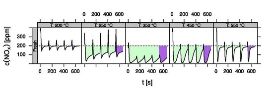
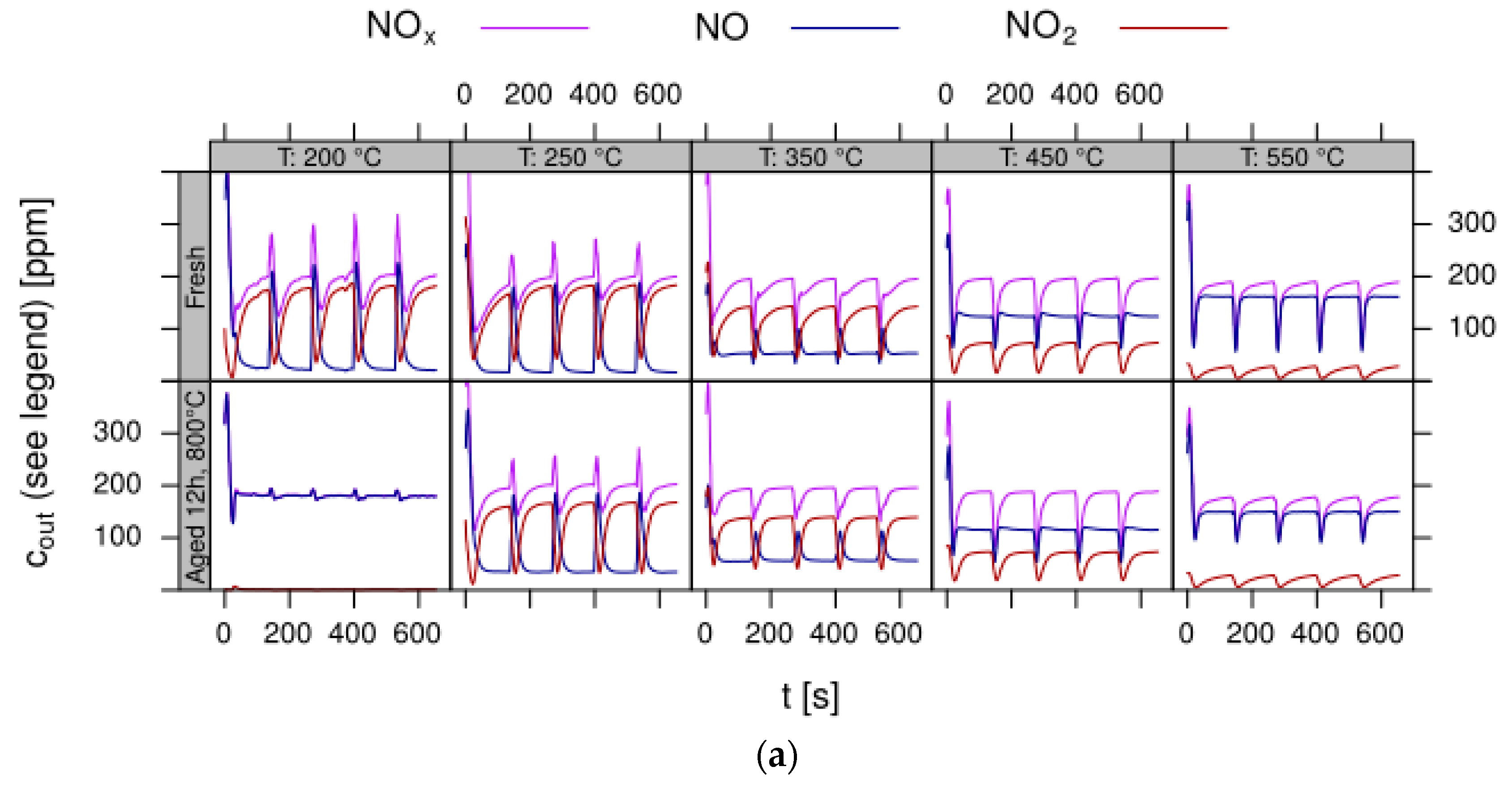
- LNT (lean NOx trap): This technology uses rich pulses to regenerate a NOx storage material. A crucial aspect for lab testing of this functionality is the ability to generate reproducible rich pulses with well-defined rich λ and pulse width. Usually 3–7 pulses are applied to each catalyst. After each rich pulse the NOx breakthrough curve is recorded for 2–10 min and integrated in several ways to calculate average NOx conversion efficiency or average NOx storage. In these tests it is important to compare NOx storage in each individual rich/lean cycle and to monitor time on stream effects. The LNT test is usually run at several temperatures covering the typical operating window. A more detailed description of the LNT test conditions is given in the Materials and Methods section.
2.4. Test Procedure
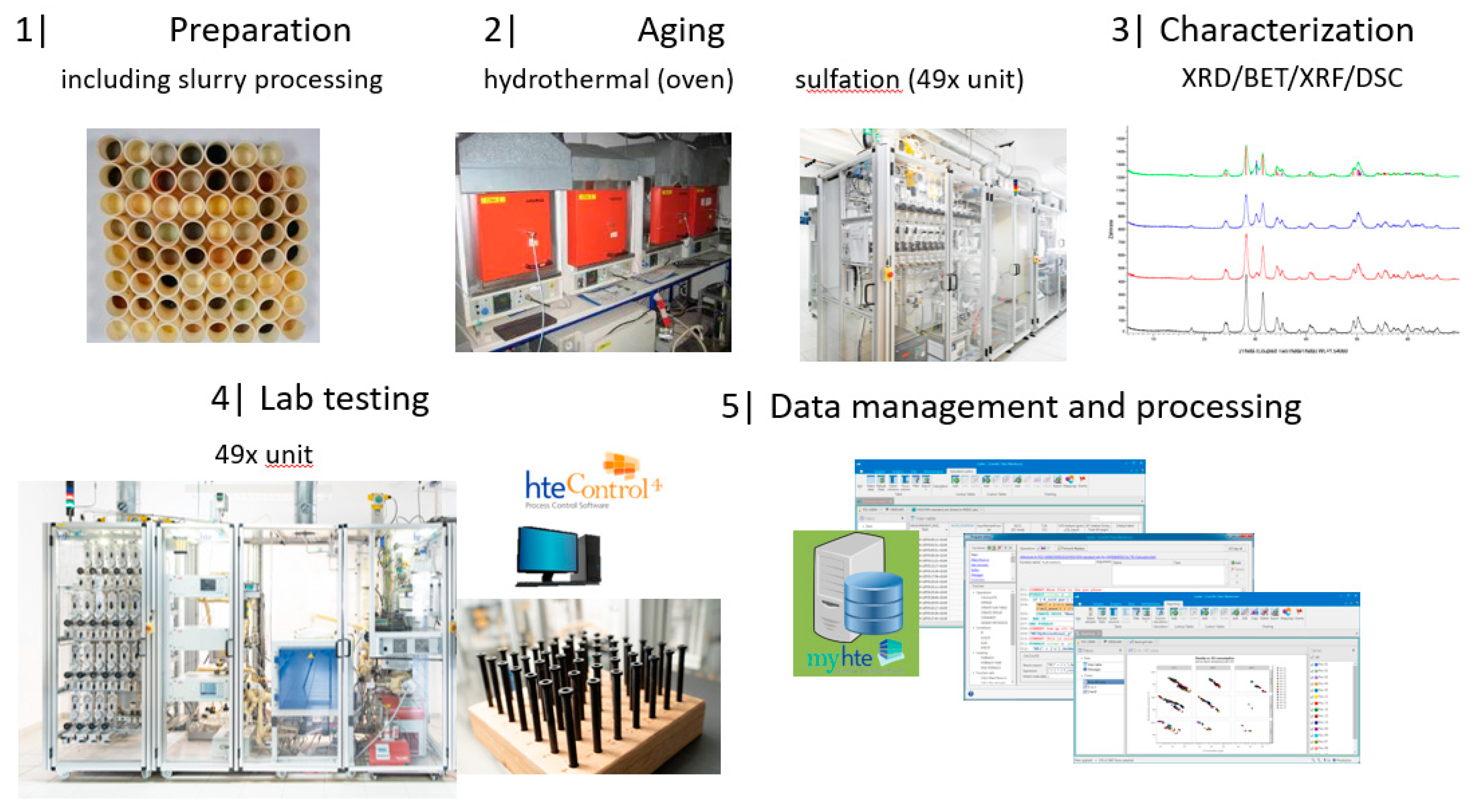
2.4.1. Catalyst Library Design and Preparation for Testing
2.4.2. Hydrothermal Aging
3. Discussion
4. Materials and Methods
- Design of sample matrix: The LNT model catalysts contained alumina as support material. This is loaded with a NOx storage component (NSC) and Pt for NO oxidation. The variation parameter in the sample matrix for this case study was the NSC composition (cf. Table 1). Different alkaline earth oxides and ZnO as individual components as well as of BaO/MO combinations (M = Mg, Ca, Sr, Zn) with a gradual replacement of BaO by another oxide on a molar basis (BaO (2/3) + MO (1/3) and BaO (1/3) + MO (2/3)) were used as NSC. In addition to the NSC variation, a baseline sample w/o NSC, i.e., 1% Pt on alumina (sample 001) was prepared. This takes into account that also the alumina support has some NOx storage capability. The references (sample 002 and 015 as repeat) contain 20 wt% BaO on alumina as NSC since Ba is typically used in state-of-the-art LNT formations. In all other samples the amount of NSC is normalized to 20 wt% on carrier BaO, other elements (Sr, Ca, Mg and Zn) replace Ba on a molar basis to get—at least in theory—an equivalent amount of active storage sites.
- Sample preparation: For sample preparation Puralox SCFa140 (Sasol, Brunsbüttel, Germany) was used as support. For each catalyst, 5 g alumina were impregnated with a solution of the corresponding alkaline earth metal nitrate using the incipient wetness technique. After careful mixing samples were dried at 100 °C and calcined for 2 h at 500 °C in air. The resulting powders were then impregnated with a solution of Pt(NH3)4(NO3)2 (CAS: 20634-12-2) using incipient wetness impregnation, dried and calcined for 1 h, 400 °C in air. As the alkaline earth metal content in each sample was normalized on a molar basis, the Pt content was set to 1 wt% based on the weight of the alumina carrier. For shaping, the calcined powders were set to slurry with D.I. water (~30 wt% solid content) and milled for 5 min at 500 rpm in a ball mill (using ZrO2 beakers and milling balls). For pure alumina this procedure was verified to result in a particle size distribution with D50 < 15 µm. The slurry was then dried under stirring and calcined for 2 h at 500 °C in air. Afterwards the resulting cake was crushed and sieved to a particle size fraction of 250–500 µm used for testing. A fraction of these shaped particles was aged for 12 h at 800 °C in a muffle oven flowed through with a stream of 10% H2O in air. Additional aliquots of selected catalysts were aged and submitted to XRD and BET analysis.
- Test procedure: For the catalytic test, sample amounts were adjusted to have the same amount of Pt in each reactor. This also ensures that, with exception of the baseline sample w/o NSC, the molar amount of the storage component is constant for the whole sample library. For the pure alumina reference, this corresponded to 200 mg diluted with corundum to simulate 1 mL coated catalyst with a washcoat loading of 3.3 g/in3. To control time on stream effects and to achieve better statistical robustness, each catalyst was tested in 3 loads, filling one plate of fresh and one plate of aged catalysts in the 48 fold parallel screening unit. Splitting the samples in this way into two plates aims at achieving maximum resolution of the NSC effect among fresh and aged samples. In the experiment, each catalyst was tested for 5 lean/rich cycles at temperatures T = 550, 450, 350, 250, 200 °C. The total flow in the measured reactor is set to meet a GHSV of 60,000 h−1 based on 1 mL bed volume. A simulated Diesel exhaust gas was mixed using mass flow controllers. During the lean phase (2 min) the feed consisted of: 200 ppm NO, 1500 pm CO, 10% O2, 6% H2O, 6% CO2, balance N2. Using fast switching magnetic valves this feed is replaced by a rich gas for 10s with minimal perturbation of the flow. In the rich phase the O2 concentration is reduced to 1% and λ is adjusted to λ = 0.95 by adding CO/H2 in a ratio of 1:3 while the concentration of other gases remains at their lean level. The gap between lean and rich flow rate is compensated by additional balance N2 added to the rich stream.
- Data processing: Throughout each experiment, the process values from all sensors (temperature, flow, pressure, gas analysers) are recorded with a frequency of 1 Hz and automatically linked by the control software to the corresponding set-points for that condition, and most importantly to the reactor position that is being tested. An example of the typical LNT raw data output at one temperature for each position is shown in Figure 5. For the whole experiment on the complete LNT matrix in the current study, taking about 4 days on the test unit close to 300,000 data points are collected for each individual sensor. Obviously, raw data are not suitable for direct catalyst comparison and data reduction is required. This data reduction process is developed when a new test protocol is implemented and automated in the control software, which e.g., averages the concentration readings for several lean/rich cycles or over a predefined time interval within a lean rich cycle. Some examples on possible sampling time intervals in LNT tests are shown in Figure 6. For efficient screening, different evaluations should be easy to configure in the data management system. In the current study, the average NOx efficiency in the lean phase of the last cycles has been used as performance indicator. The reduced data sets are then stored in a relational database system (“myhte” data warehouse) from which they can be retrieved for further processing (e.g., R, a language and environment for statistical computing was used for analysis in the current case) [39]. For results stored in the database it is possible to relate individual measurements, such as using the inlet concentration measured for the by-pass line to calculate conversion.For the LNT application, an important step is the calculation of the average NOx efficiencies and product distribution (e.g., NO2/NOx ratio) within different time windows or after a certain time of the lean phase. The overall process of calculating relevant parameters for the LNT application has been implemented as an automated data processing workflow. Even for an experiment on 48 different samples (see Figure 9 and Figure 10) evaluation is a routine task which requires only little human interaction. In hte’s lab, similar workflows have been established for other test protocols, some of them, such as automated extraction of light-off temperatures have been described elsewhere [33,34].
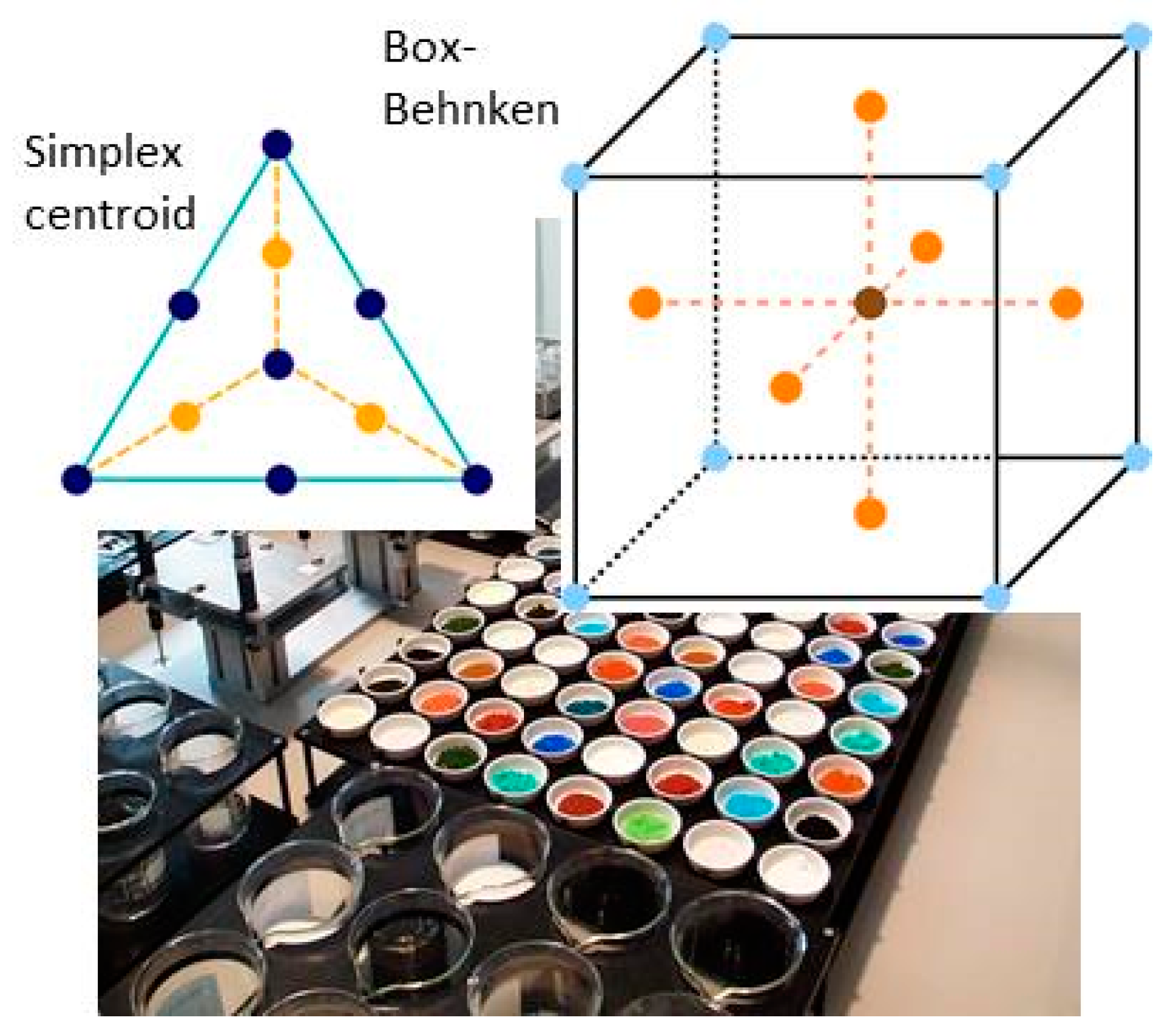
- DoE evaluation: In most cases, experiments in HT screening involve catalyst libraries that are designed based on principles of statistical design of experiments (DoE) [2,3], rather than a collection of unrelated catalysts. The goal of a DoE is it identify cause-effect relationships between the parameters controlled in the experiment (such as composition, thermal activation, or other treatments like milling or binders) and the observed catalyst performance. If possible, samples of a library are prepared and aged together with a reference of known performance to avoid aliasing of effects by uncontrolled factors and errors. If libraries cannot be fit into a single plate, some care has to be taken to control statistical error by introducing proper blocking factors e.g., using split plot designs. Depending on the amount of prior knowledge, either DoEs for factor screening in an early stage (such as fractional factorial designs) or response surface design methodologies can be applied. In the current case a factor screening (impact of different elements as NSC) was attempted. By screening the concentration at three levels also secondary effects can be resolved by the DoE. As the capacity of the 48-fold parallel reactor naturally limits the number of samples, in the current case the variable “Aging” was used as a splitting factor because we were mainly interested in the effect of composition before and after aging. In less obvious cases, computer-generated optimal designs such as D-optimal designs are required to ensure that split-block design constraints do not introduce uncontrolled statistical bias. However, in the current case the hydrothermal aging had such a dramatic effect that this was not critical. As additional QC measure protect against creeping loss of precision, it is advisable to include at least one standard sample into every experimental plate to control effects caused by sensor aging or contamination of the equipment. Specifically, for parallel reactors it is critical to avoid that factors of the experimental design are aliased with respect to either reactor position or time on stream. If time on stream effects can be expected as in the current case of storage catalysts, testing multiple loads of at least some samples helps to make experiments more robust.
Author Contributions
Funding
Conflicts of Interest
References
- Heck, R.M.; Farrauto, R.J.; Gulati, S.T. Catalytic Air Pollution Control, Commercial Technology, 3rd ed.; John Wiley & Sons: Hoboken, NJ, USA, 2009; ISBN 978-0-470-27503-0. [Google Scholar]
- Montgomery, D.C. Design and Analysis of Experiments, 8th ed.; John Wiley & Sons: Hoboken, NJ, USA, 2012; ISBN 1118146921. [Google Scholar]
- Box, G.E.P.; Hunter, J.S.; Hunter, W.G. Statistics for Experimenters: Design, Innovation, and Discovery, 2nd ed.; Wiley: New York, NY, USA, 2005; ISBN 978-0-471-71813-0. [Google Scholar]
- Senkan, S.M. High-throughput screening of solid-state catalyst libraries. Nature 1998, 394, 350–353. [Google Scholar] [CrossRef]
- Rodemerck, U.; Wolf, D.; Buyevskaya, O.V.; Claus, P.; Senkan, S.; Baerns, M. High-throughput synthesis and screening of catalytic materials: Case study on the search for a low-temperature catalyst for the oxidation of low-concentration propane. Chem. Eng. J. 2001, 82, 3–11. [Google Scholar] [CrossRef]
- Hendershot, R.J.; Lasko, S.S.; Fellmann, M.F.; Oskarsdottir, G.; Delgass, W.N.; Snively, C.M.; Lauterbach, J. A novel reactor system for high throughput catalyst testing under realistic conditions. Appl. Catal. A Gen. 2003, 254, 107–120. [Google Scholar] [CrossRef]
- Lucas, M.; Claus, P. High throughput screening in monolith reactors for total oxidation reactions. Appl. Catal. A Gen. 2003, 254, 35–43. [Google Scholar] [CrossRef]
- Mills, P.L.; Nicole, J.F. A novel reactor for high-throughput screening of gas-solid catalyzed reactions. Chem. Eng. Sci. 2004, 59, 5345–5354. [Google Scholar] [CrossRef]
- Paul, J.S.; Jacobs, P.A.; Weiss, P.-A.W.; Maier, W.F. Combinatorial discovery of new catalysts for the selective oxidation of isobutene. Appl. Catal. A Gen. 2004, 265, 185–193. [Google Scholar] [CrossRef]
- Hendershot, R.J.; Snively, C.M.; Lauterbach, J. High-Throughput Heterogeneous Catalytic Science. Chem. Eur. J. 2005, 11, 806–814. [Google Scholar] [CrossRef] [PubMed]
- Zech, T.; Bohner, G.; Klein, J. High-throughput screening of supported catalysts in massively parallel single-bead microreactors: Workflow aspects related to reactor bonding and catalyst preparation. Catal. Today 2005, 110, 58–67. [Google Scholar] [CrossRef]
- Brooks, C.; Cypes, S.; Grasselli, R.K.; Hagemeyer, A.; Hogan, Z.; Lesik, A.; Streukens, G.; Volpe, A.F., Jr.; Turner, H.W.; Weinberg, W.H.; et al. High throughput discovery of CO oxidation/VOC combustion and water-gas shift catalysts for industrial multi-component streams. Top. Catal. 2006, 38, 195–209. [Google Scholar] [CrossRef]
- Farrusseng, D. High-throughput heterogeneous catalysis. Surf. Sci. Rep. 2008, 63, 487–513. [Google Scholar] [CrossRef]
- Moehmel, S.; Steinfeldt, N.; Engelschalt, S.; Holena, M.; Kolf, S.; Baerns, M.; Dingerdissen, U.; Wolf, D.; Weber, R.; Bewersdorf, M. New catalytic materials for the high-temperature synthesis of hydrocyanic acid from methane and ammonia by high-throughput approach. Appl. Catal. A Gen. 2008, 334, 73–83. [Google Scholar] [CrossRef]
- Turner, H.W.; Volpe, A.F., Jr.; Weinberg, W.H. High-throughput heterogeneous catalyst research. Surf. Sci. 2009, 603, 1763–1769. [Google Scholar] [CrossRef]
- Gaudillere, C.; Vernoux, P.; Mirodatos, C.; Caboche, G.; Farrusseng, D. Screening of ceria-based catalysts for internal methane reforming in low temperature SOFC. Catal. Today 2010, 157, 263–269. [Google Scholar] [CrossRef]
- Valtchev, M.; Hammes, M.; Richter, R.; Holtzen, H.; Stowe, K.; Maier, W.F. Corrosion-Resistant Parallel Fixed-Bed Reactors for High-Throughput Screening of New Deacon Reaction Catalysts. Chem. Eng. Technol. 2014, 37, 1251–1260. [Google Scholar] [CrossRef]
- Hagemeyer, A.; Volpe, A.F. (Eds.) Modern Applications of High Throughput R&D in Heterogeneous Catalysis; Bentham Science Publishers: Sharjah, UAE, 2014; eISBN 978-1-60805-872-3, ISBN 978-1-60805-873-0. [Google Scholar] [CrossRef]
- Zhu, H.B.; Laveille, P.; Rosenfeld, D.C.; Hedhili, M.N.; Basset, J.M. A high-throughput reactor system for optimization of Mo-V-Nb mixed oxide catalyst composition in ethane ODH. Catal. Sci. Technol. 2015, 5, 4164–4173. [Google Scholar] [CrossRef]
- Luneau, M.; Schuurman, Y.; Meunier, F.C.; Mirodatos, C.; Guilhaume, N. High-throughput assessment of catalyst stability during autothermal reforming of model biogas. Catal. Sci. Technol. 2015, 5, 4390–4397. [Google Scholar] [CrossRef]
- Luchters, N.T.J.; Fletcher, J.V.; Roberts, S.J.; Fletcher, J.C.Q. Variability of Data in High Throughput Experimentation for Catalyst Studies in Fuel Processing. Bull. Chem. React. Eng. Catal. 2017, 12, 106–112. [Google Scholar] [CrossRef]
- Emmanuel, J.; Hayden, B.E.; Saleh-Subaie, J. The particle size dependence of CO oxidation on model planar titania supported gold catalysts measured by parallel thermographic imaging. J. Catal. 2019, 369, 175–180. [Google Scholar] [CrossRef]
- Pfeifer, M.; Schwarz, T.; Stöwe, K. Quaternäre Metall/Metalloxid-Katalysatoren als Wandkatalysatoren in Mikroreaktoren für Power-to-Gas-Applikationen mittels kombinatorischer Hochdurchsatzmethoden. Chem. Ing. Tech. 2019, 91, 607–613. [Google Scholar] [CrossRef]
- Brenner, A.; Schüth, F.; Schunk, S.A.; Stichert, W. Anordnung zum Testen der Katalytischen Aktivität von einem Reaktionsgas ausgesetzten Feststoffen. Patent DE 198 61 316 B4, 6 March 1998. [Google Scholar]
- Haas, A.; Strehlau, W.; Brenner, A.; Koechel, O.; Friess, M.; Zech, T. Device and Method for Pressure and Flow Control in Parallel Reactors. U.S. Patent WO 2005063372 A2, 26 May 2009. [Google Scholar]
- Strehlau, W.; Gerlach, O.; Maier, J.; Gabriel, T. Catalysts for the Simultaneous Removal of Carbon Monoxide and Hydrocarbons from Oxygen-Rich Exhaust Gases and Processes for the Manufacture Thereof. U.S. Patent WO 2005/102513 A1, 11 October 2007. [Google Scholar]
- Strehlau, W.; Gerlach, O.; Maier, J.; Gabriel, T. Catalyst for the Treatment of Exhaust Gases and Processes for Producing the Same. U.S. Patent WO 2006/120013 A1, 18 September 2008. [Google Scholar]
- Hendershot, R.J.; Rogers, W.B.; Snively, C.A.; Ogunnaike, B.A.; Lauterbach, J. Development and optimization of NOx storage and reduction catalysts using statistically guided high-throughput experimentation. Catal. Today 2004, 98, 375–385. [Google Scholar] [CrossRef]
- Hendershot, R.J.; Vijay, R.; Snively, C.M.; Lauterbach, J. High-throughput study of the performance of NOx storage and reduction catalysts as a function of cycling conditions and catalyst composition. Chem. Eng. Sci. 2006, 61, 3907–3916. [Google Scholar] [CrossRef]
- Iojoiu, E.E.; Bassou, B.; Guilhaume, N.; Farrusseng, D.; Desmartin-Chomel, A.; Lombaert, K.; Bianchi, D.; Mirodatos, C. High-throughput approach to the catalytic combustion of diesel soot. Catal. Today 2008, 137, 103–109. [Google Scholar] [CrossRef]
- Kern, P.; Klimczak, M.; Heinzelmann, T.; Lucas, M.; Claus, P. High-throughput study of the effects of inorganic additives and poisons on NH3-SCR catalysts. Part II: Fe–zeolite catalysts. Appl. Catal. B Environ. 2010, 95, 48–56. [Google Scholar] [CrossRef]
- Gärtner, A.; Lenk, T.; Kiemel, R.; Casu, S.; Breuer, C.; Stöwe, K. High-Throughput Screening Approach to Identify New Catalysts for Total Oxidation of Methane from Gas Fueled Lean Burn Engines. Top. Catal. 2016, 59, 1071–1075. [Google Scholar] [CrossRef]
- Sundermann, A.; Gerlach, O. High-Throughput Screening Technology for Automotive Applications. Chem. Ing. Tech. 2014, 86, 1941–1947. [Google Scholar] [CrossRef]
- Sundermann, A.; Gerlach, O. High-Throughput Screening as a Supplemental Tool for the Development of Advanced Emission Control Catalysts: Methodological Approaches and Data Processing. Catalysts 2016, 6, 23. [Google Scholar] [CrossRef]
- Kim, M.Y.; Park, J.J.; Lee, B.M.; Kang, H.; Song, J.; Na, S.; Han, H.S. High Throughput Vehicle Test for Spatiotemporal Emissions Evaluation; SAE Technical Paper 2018-01-0642; SAE International: Warrendale, PA, USA, 2018. [Google Scholar] [CrossRef]
- Maurer, M.; Holler, P.; Zarl, S.; Fortner, T.; Eichlseder, H. Investigations of Lean NOx Trap (LNT) Regeneration Strategies for Diesel Engines; SAE Technical Paper 2017-24-0124; SAE International: Warrendale, PA, USA, 2017. [Google Scholar] [CrossRef]
- Kim, D.H.; Chun, Y.-H.; Muntean, G.G.; Yezeretz, A.; Currier, N.W.; Epling, W.S.; Chen, H.-Y.; Hess, H.; Peden, C.H.F. Relationship of Pt particle size to the NOx storage performance of thermally aged Pt/BaO/Al2O3 lean NOx trap catalysts. Ind. Eng. Chem. Res. 2006, 45, 8815–8821. [Google Scholar] [CrossRef]
- Fridell, E.; Skoglundh, M.; Westerberg, B.; Johansson, S.; Smedler, G. NOx Storage in Barium-Containing Catalysts. J. Catal. 1999, 183, 196–209. [Google Scholar] [CrossRef]
- R Foundation for Statistical Computing, Vienna, Austria. Available online: http://www.R-project.org/ (accessed on 14 September 2019).


| Sample No. | BaO | SrO | CaO | MgO | ZnO | Comment |
|---|---|---|---|---|---|---|
| 001 | 0 | 0 | 0 | 0 | 0 | Base line |
| 002 | 1 | 0 | 0 | 0 | 0 | Main effect Ba |
| 003 | 0 | 1 | 0 | 0 | 0 | Main effect Sr |
| 004 | 0 | 0 | 1 | 0 | 0 | Main effect Ca |
| 005 | 0 | 0 | 0 | 1 | 0 | Main effect Mg |
| 006 | 0 | 0 | 0 | 0 | 1 | Main effect Zn |
| 007 | 2/3 | 1/3 | 0 | 0 | 0 | Interaction Ba:Sr + Sr concentration |
| 008 | 1/3 | 2/3 | 0 | 0 | 0 | |
| 009 | 2/3 | 0 | 1/3 | 0 | 0 | Interaction Ba:Ca + Ca concentration |
| 010 | 1/3 | 0 | 2/3 | 0 | 0 | |
| 011 | 2/3 | 0 | 0 | 1/3 | 0 | Interaction Ba:Mg + Mg concentration |
| 012 | 1/3 | 0 | 0 | 2/3 | 0 | |
| 013 | 2/3 | 0 | 0 | 0 | 1/3 | Interaction Ba:Zn + Zn concentration |
| 014 | 1/3 | 0 | 0 | 0 | 2/3 | |
| 015 | 1 | 0 | 0 | 0 | 0 | Repeat of 002 |
| Sample No. | Description | BET Fresh [m2/g] | BET Aged [m2/g] |
|---|---|---|---|
| 001 | SCFa140 | 136.7 | 114.2 |
| 002 | BaO/SCFa140 | 115.5 | 96.9 |
| 003 | SrO/SCFa140 | 129.2 | 98.4 |
| 004 | CaO/SCFa140 | 123.1 | 110.5 |
| 005 | MgO/SCFa140 | 132.9 | 115.4 |
| 006 | ZnO/SCFa140 | 124.5 | 106.3 |
| Dopant | 200 °C | 250 °C | 350 °C | 450 °C | 550 °C | |||||
|---|---|---|---|---|---|---|---|---|---|---|
| Fresh | Aged | Fresh | Aged | Fresh | Aged | Fresh | Aged | Fresh | Aged | |
| Ba | 117 | 5 | 591 | 47 | 1528 | 292 | 1193 | 346 | 421 | 381 |
| Ba/Ca 2:1 | 76 | 0 | 436 | 31 | 1452 | 344 | 1144 | 380 | 399 | 377 |
| Ba/Ca 1:1 | 56 | 6 | 316 | 39 | 1310 | 297 | 758 | 365 | 312 | 387 |
| Ca | 101 | 12 | 290 | 36 | 940 | 169 | 436 | 310 | 279 | 377 |
| Ba/Mg 2:1 | 161 | 2 | 631 | 44 | 1498 | 292 | 1081 | 317 | 406 | 378 |
| Ba/Mg 1:1 | 75 | 6 | 371 | 25 | 1203 | 194 | 678 | 281 | 325 | 340 |
| Mg | 172 | 5 | 137 | 20 | 347 | 132 | 228 | 245 | 265 | 324 |
| Ba/Sr 2:1 | 125 | 8 | 464 | 43 | 1537 | 323 | 1219 | 405 | 425 | 387 |
| Ba/Sr 1:1 | 77 | 6 | 302 | 39 | 1399 | 359 | 909 | 413 | 344 | 387 |
| Sr | 53 | 12 | 260 | 47 | 1116 | 265 | 669 | 352 | 318 | 370 |
| Ba/Zn 2:1 | 106 | 2 | 592 | 28 | 1590 | 312 | 1307 | 346 | 430 | 361 |
| Ba/Zn 1:1 | 82 | 0 | 168 | 6 | 957 | 193 | 495 | 270 | 267 | 319 |
| Zn | 70 | 0 | 74 | 0 | 246 | 91 | 176 | 206 | 228 | 296 |
| no dopant | 88 | 0 | 82 | 3 | 211 | 91 | 174 | 242 | 254 | 324 |
© 2019 by the authors. Licensee MDPI, Basel, Switzerland. This article is an open access article distributed under the terms and conditions of the Creative Commons Attribution (CC BY) license (http://creativecommons.org/licenses/by/4.0/).
Share and Cite
Sundermann, A.; Kögel, M.; Gerlach, O. Screening NOx Storage Performance—Demonstrating a High Throughput Approach for Evaluating Emission Control Catalysts under Transient Conditions. Catalysts 2019, 9, 776. https://doi.org/10.3390/catal9090776
Sundermann A, Kögel M, Gerlach O. Screening NOx Storage Performance—Demonstrating a High Throughput Approach for Evaluating Emission Control Catalysts under Transient Conditions. Catalysts. 2019; 9(9):776. https://doi.org/10.3390/catal9090776
Chicago/Turabian StyleSundermann, Andreas, Markus Kögel, and Olga Gerlach. 2019. "Screening NOx Storage Performance—Demonstrating a High Throughput Approach for Evaluating Emission Control Catalysts under Transient Conditions" Catalysts 9, no. 9: 776. https://doi.org/10.3390/catal9090776
APA StyleSundermann, A., Kögel, M., & Gerlach, O. (2019). Screening NOx Storage Performance—Demonstrating a High Throughput Approach for Evaluating Emission Control Catalysts under Transient Conditions. Catalysts, 9(9), 776. https://doi.org/10.3390/catal9090776