Article

Development of TiO2-Carbon Composite Acid Catalyst for Dehydration of Fructose to 5-Hydroxymethylfurfural

by
Morongwa Martha Songo
1,2,
Richard Moutloali
2 and
Suprakas Sinha Ray
1,2,*
1
DST-CSIR National Centre for Nanostructured Materials, Council for Scientific and Industrial Research, Pretoria 0001, South Africa
2
Department of Applied Chemistry, University of Johannesburg, Doornfontein, Johannesburg 2028, South Africa
*
Author to whom correspondence should be addressed.
Catalysts 2019, 9(2), 126; https://doi.org/10.3390/catal9020126
Submission received: 28 December 2018 / Revised: 22 January 2019 / Accepted: 29 January 2019 / Published: 31 January 2019
(This article belongs to the Special Issue Emerging Trends in TiO2 Photocatalysis and Applications)

Abstract

:
A TiO2-Carbon (TiO2C) composite was prepared using the microwave-assisted method and sulfonated using fuming sulfuric acid to produce a TiO2C solid acid catalyst. The prepared solid acid catalyst was characterised using scanning electron microscopy, Brunauer-Emmett-Teller analysis, Fourier transform infrared spectroscopy, and X-ray diffraction. Crystallinity analysis confirmed that TiO2C has an anatase structure, while analysis of its morphology showed a combination of spheres and particles with a diameter of 50 nm. The TiO2C solid acid catalyst was tested for use in the catalytic dehydration of fructose to 5-hydroxymethylfurfural (5-HMF). The effect of reaction time, reaction temperature, catalyst dosage, and solvent were investigated against the 5-HMF yield. The 5-HMF yield was found to be 90% under optimum conditions. The solid acid catalyst is very stable and can be reused for four catalytic cycles. Hence, the material has great potential for use in industrial applications and can be used for the direct conversion of fructose to 5-HMF because of its high activity and high reusability.

1. Introduction

Increase in the usage of fossil fuels for the production of chemicals and energy has caused not only a rise in greenhouse gas emissions into the atmosphere, but also water pollution, thereby contributing to the growing number of serious health issues. These side effects have spurred researchers to look for alternative ways of producing valuable chemicals and energy using sustainable and renewable resources. Biomass has been identified as a promising resource for the sustainable production of valuable chemical feedstocks and fuels [1]. 5-hydroxymethylfurfural (5-HMF) has been recognised as a key intermediate in the production of biorenewable chemicals [2] and has been classified as a “platform molecule” because it is an important chemical building block used to derive a variety of chemicals, pharmaceuticals, and furane-based polymers [3].
5-HMF is usually synthesised from the dehydration of fructose or glucose using homogeneous organic acids or heterogeneous solid acid catalysts [4]. Although the use of homogeneous catalysts produces high fructose conversion and high dehydrations of 5-HMF, there are drawbacks with regard to separation, recycling, and equipment corrosion [5,6]. Heterogeneous acid catalysts such as mesoporous zirconium phosphate [7,8], sulfonated metal oxides [9], magnetite mixed-metal oxides [10], and functionalised silica nanoparticles [11,12] have been used for the dehydration of fructose to 5-HMF. Although the use of some of these materials has promising results, the studies cited pointed out the remaining challenge of finding catalysts that are highly active, selective, chemically and structurally stable during repeated use, and do not lead to any side reactions (by-products). Biomass-derived carbonaceous materials were found to be promising candidates for catalytic support application because of their low cost of production and thermal stability [13]. For example, Wang et al. [14] used a sulfonated carbonaceous solid acid catalyst for the dehydration of fructose into 5-HMF in dimethyl sulfoxide (DMSO). Their catalyst was very efficient and effective in that it converted 96.1% of the fructose for a high 5-HMF yield of 93.4%. Zhao et al. [15] further explored a sulfonated carbon sphere solid acid catalyst that converted 100% of the fructose in DMSO solvent at 160 °C for 1.5 h to produce 90% 5-HMF. Wang et al. [16] used C-based solid acid catalysts to catalyse dehydration of fructose in DMSO for 1.5 h at 130 °C to achieve 91.2% 5-HMF. Guo et al. [17] used a lignin-derived carbonaceous catalyst to convert fructose into 5-HMF under microwave irradiation in the mixture of DMSO and ionic liquid at 110 °C for 10 min for a fructose conversion of 98% and a 5-HMF yieldof 84%. Hu et al. [18] explored the use of a magnetic lignin-derived carbonaceous acid catalyst for the catalytic conversion of fructose into 5-HMF in DMSO solvent. Use of the magnetic C-based catalyst achieved a 100% fructose conversion and a 5-HMF yieldof 81.1% under optimum reaction conditions.
Studies have found that the anatase phase of TiO2 can catalyse the dehydration of carbohydrates such as fructose and glucose into 5-HMF and that the performance of the TiO2 catalyst is strongly controlled by its morphological and structural properties [3,19,20,21]. For example, the use of nanostructured TiO2 remarkably favoured the production of 5-HMF from glucose and fructose [19,20], with its high activity being ascribed to the morphology of the nanoparticles [20].
In this paper, we report the synthesis, characterisation, and application of TiO2-Carbon sphere (TiO2C) composite for the catalysis of the dehydration of fructose into 5-HMF in DMSO solvent. To the best of our knowledge, there have been no reports on the use of TiO2C as a catalyst for the dehydration of fructose into 5-HMF. We synthesised the TiO2C composites using a microwave-assisted method. Because TiO2 has redox acidic sites, Bronsted acid sites were introduced by sulfonating the TiO2C composites with concentrated sulfuric acid. Scanning electron microscopy (SEM), Brunauer-Emmett-Teller (BET) analysis, X-ray diffraction, and Fourier transform infrared (FTIR) spectroscopy were used to characterise the TiO2C acid catalyst. This solid acid catalyst was tested in DMSO solvent as a catalyst for the dehydration of fructose into 5-HMF. To achieve a higher dehydration of 5-HMF, reaction parameters such as reaction temperature, reaction time, and catalyst amount were optimised. Moreover, the ability to recycle the catalyst was studied to evaluate its catalytic stability.

2. Experimental and Methods

2.1. Materials

All chemicals used for synthesising the TiO2 nanoparticles (NPs) and TiO2C composites were purchased from Sigma-Aldrich Corporation (St. Louis, MO, USA). Titanium (IV) isopropoxide (TTIP) and fructose were used as precursors in the preparation of TiO2 and TiO2C composites. Polyvinylpyrrolidone (PVP) was used as a surfactant and ammonium hydroxide was used as a reducing agent for the preparation of TiO2 NPs. Sulfuric acid was used for sulfonating the TiO2C solid acid catalyst.

2.2. Preparation of TiO2 Nanoparticles Using the Sol-Gel Method

Ethanol (50 mL) was mixed with 17.79 g of TTIP and stirred for 30 min. PVP (4 g) was added to the mixture, which then was stirred at 70 °C until it was completely dissolved. Next, 4 mL of NH3·2H2O was added. The solution was heated at 90 °C under reflux conditions for 24 h. The resultant sample was washed with water and dried at 100 °C for 24 h.

2.3. Preparation of Carbon Spheres Using the Microwave-Assisted Method

The carbon precursor (fructose) was mixed with deionised (DI) water and stirred at room temperature (25 to 27 °C) for 2 h. The obtained mixture was transferred into microwavable plastic vessels that were then placed into the ultraclave high-performance microwave reactor and allowed to react at 180 °C for 2 h.

2.4. Preparation of TiO2C Composites Using the Microwave-Assisted Method

TiO2 nanoparticles were added to 50 mL of DI water. The solution was sonicated at 30 °C for at least 1 h, after which the fructose was added. The pH of the solution was adjusted to 2. The solution was stirred at room temperature (25 to 27 °C) for 2 h and then microwaved in the ultraclave high-performance microwave reactor for another 2 h at 180 °C. The resultant sample was washed three times with DI water, dried at 150 °C for 24 h, and then calcined at 500 °C for 2 h. Different amounts of TiO2 nanoparticles (1, 5, and 10%) were loaded onto the carbon spheres. For example, to prepare the 1%TiO2C nanocomposite, 0.1 g of TiO2 nanoparticles was added to 9.9 g of fructose, whereas to prepare the 5%TiO2C and 10%TiO2C, the mass ratio of TiO2 nanoparticles to fructose was 0.5:9.5 and 1:9, respectively. The TiO2C composites loaded with 1, 5, and 10% TiO2 were denoted as 1%TiO2C, 5%TiO2C, and 10%TiO2C, respectively.

2.5. Preparation of the Sulfonated Carbon and TiO2C Acid Catalysts

TiO2C was sulfonated by adding 1 g of TiO2C composite to 25 ml of concentrated sulfuric acid and stirring the solution at 120 °C for 24 h under reflux conditions. The sulfonated samples, denoted as TiO2C_S, were washed with DI water and dried at 150 °C for 24 h. The carbon spheres were sulfonated using the same method and were denoted as C_S.

2.6. Surface Acid Measurement Tests

A total of 100 mg of C_S and TiO2C_S composite acid catalysts was mixed with 50 ml of DI water and 40 ml of 0.01 M NaOH and stirred at room temperature (25 to 27 °C) overnight [22]. The solution was filtered and titrated with 0.1 N of oxalic acid using phenolphthalein as the indicator.

2.7. Characterisation

Elemental composition and surface morphology analyses were conducted using the AURIGA® scanning electron microscope (Zeiss, Oberkochen, Germany). The crystallinity and phase composition were investigated using the PanAlytical X’Pert Pro (Panalytical Ltd., Eindhoven, The Netherlands). The functional groups of the catalysts were measured in the wavelength range of 550–4000 cm−1 using a Spectrum 100 FTIR spectrometer (PerkinElmer, Waltham, MA, USA). The specific surface area, pore volume, and pore size were measured using the ASAP 2020 BET analysis system (Micromeritics Instruments Corp., Norcross, GA, USA).

2.8. Catalytic Testing

Fructose (0.5 g), DMSO (6 ml), and catalyst (0.1 g) were placed in a vessel and allowed to react for 1 h at 120 °C using the ultraclave high-performance microwave reactor. After the reaction, the solution was centrifuged to separate the solid catalyst particles from the liquid, and the supernatant liquid was analysed using a Lambda UV-Vis spectrometer Model 750s (PerkinElmer, Shelton, CT, USA) at the wavelength of 284 nm.

2.9. Reusability Studies

Reusability of the materials was studied using the dehydration of fructose into 5-HMF in DMSO as an illustrative reaction. The C_S and TiO2C_S composite acid catalysts were allowed to react for 1 h in separate vessels and then were separated from the solution by centrifugation. The recovered catalysts were then washed thoroughly with DI water and ethanol and dried for 4 h at 90 °C. This process was repeated four times, with the 5-HMF yield calculated each time.

2.10. Hot Filtration Tests

The 1%TiO2C_S, 5%TiO2C_S, and 10%TiO2C_S acid catalysts were used to perform hot filtration tests to determine the heterogeneous nature of the acid catalyst. In a typical procedure, 0.5 g of fructose and 0.1 g of TiO2C_S were added to 6 ml of DMSO and allowed to react for 30 min using the ultraclave high-performance microwave reactor. After the reaction, the solution was allowed to cool down and then was centrifuged to separate the catalyst from the reaction mixture. The solution was analysed using a UV-Vis spectrometer at a wavelength of 284 nm. The same reaction was repeated for 1 h using the solution filtrate without adding the substrate.

3. Results and Discussion

3.1. BET Surface Area and Pore Volume of the Catalysts

The BET surface area and pore volume of the carbon spheres and the various compositions of the TiO2C composites are presented in Table 1. The carbon spheres had a surface area of 517 m2/g before sulfonation. However, a reduction in surface area was observed after adding TiO2 NPs to the carbon due to TiO2 NPs blocking some of the micropores of the carbon. The TiO2C composite loaded with the lowest dosage of TiO2 NPs (i.e., 1%TiO2C) had a larger surface area and pore volume of 413 m2/g and 0.26 cm3/g, respectively, than the composites loaded with higher amounts of TiO2 (i.e., 5%TiO2C and 10%TiO2C). The surface area of the TiO2C composite decreased when a high loading of TiO2 NPs was introduced onto the carbonaceous support. The 1%TiO2C composite had the highest pore volume of 0.26 cm3/g compared to that of 5%TiO2C and 10%TiO2C composites. Both the surface area and the pore volume were affected by functionalising the carbon spheres and TiO2C with concentrated sulfuric acid. After sulfonation, the surface area of the carbon spheres decreased from 517 to 167 m2/g and that of the 1%TiO2C, 5%TiO2C, and 10%TiO2C composites decreased from 413 to 83, 273 to 61, and 202 to 59 m2/g, respectively. Pore volume also decreased. The reduction in surface area and pore volume might be attributed to the SO3H groups that were attached to the pores of the carbon spheres and TiO2C composites during sulfonation. Other researchers reported similar results [21,22]. For example, Tamborini et al. [21] synthesised sulfonated porous carbon materials and used them for the production of biodiesel. The surface areas of the different synthesised carbons (PC100S and PC200S) were 630 and 695 m2/g, respectively. The sulfonation process decreased the surface area of PC100S to 470 m2/g and that of PC200S to 140 m2/g. The pore volume of the carbon materials also decreased from 0.92 to 0.77 cm3/g and from 1 to 0.34 cm3/g, respectively. Sulfonation corroded the microporosity and mesoporosity of these carbon materials. Liu et al. [22] prepared a carbon-based acid catalyst and used it for the esterification of acetic acid with ethanol. After sulfonation, the surface area and pore volume of the activated carbon decreased from 751 to 602 m2/g and from 0.47 to 0.38 cm3/g, respectively. Their findings suggested that SO3H groups were grafted onto the pore spaces of the activated carbons.
The acid strength of C_S, 1%TiO2C_S, 5%TiO2C_S, and 10%TiO2C_S was calculated to be 1.46, 1.55, 1.49, and 1.36 mmol g−1, respectively, as seen in Table 1. The acid distribution results confirmed that SO3H acid sites were introduced onto the surface of the prepared catalysts, verifying the strong adsorption bands of the S=O group at 1180 and 1008 cm−1, which were associated with the SO3 groups in the FTIR spectra discussed in Section 3.3.
The heterogeneous nature of the 1%TiO2C_S, 5%TiO2C_S, and 10%TiO2C_S acid catalysts was evaluated using hot filtration tests conducted at optimum conditions. The results showed that leaching of SO3H functional groups did not occur during the dehydration of fructose to 5-HMF. The 5-HMF dehydration was about 80% after 30 min of reaction. The reaction was repeated again for 1 h and showed that the HMF dehydration did not improve beyond 80%. These findings confirmed that the TiO2C_S acid catalysts are heterogeneous and that the functional groups were strongly attached to the surface of the TiO2C_S catalysts, so leaching did not occur.

3.2. Surface Morphology

The SEM images of the neat carbon and neat TiO2C composites are shown in Figure 1a–d, and those of the C_S and TiO2C_S acid catalysts are shown in Figure 1e–h. The neat carbon was spherical and had a smooth surface, with the spheres agglomerated and interconnected (Figure 1a). The neat 1%TiO2C_S, 5%TiO2C_S, and 10%TiO2C_S composites consisted of a combination of interconnected spheres and small TiO2 particles which did not have a definite shape, and were aggregated (Figure 1b–d). Moreover, a high amount (5 and 10 wt.%) of TiO2 NPs loading promoted the formation of irregular TiO2 particles in the TiO2C composites. After sulfonation, the particles were found to have shrunk, as seen in Figure 1f–h, whereas in a case of C_S the spheres were found to have enlarged as shown in Figure 2e.
Figure 2 shows the high magnification SEM images of (a) C_S solid acid catalyst, (b) 1%TiO2C_S, (c) 5%TiO2C_S, (d) 10%TiO2C_S and (e) sulfonated TiO2. From Figure 2a, we can see that the C_S solid acid catalyst had a smooth surface, whereas the 1%TiO2C_S and 5%TiO2_S showed the presence of small traces of TiO2 particles which were deposited onto the carbon surface. In the 10%TiO2C_S sample (Figure 2d) TiO2 particles were deposited on the surface of the carbon. However, these TiO2 particles were not homogeneously distributed onto the surface of the carbon. In the sulfonated TiO2 sample (Figure 2e); SEM revealed that TiO2 particles had irregular shaped and were agglomerated.
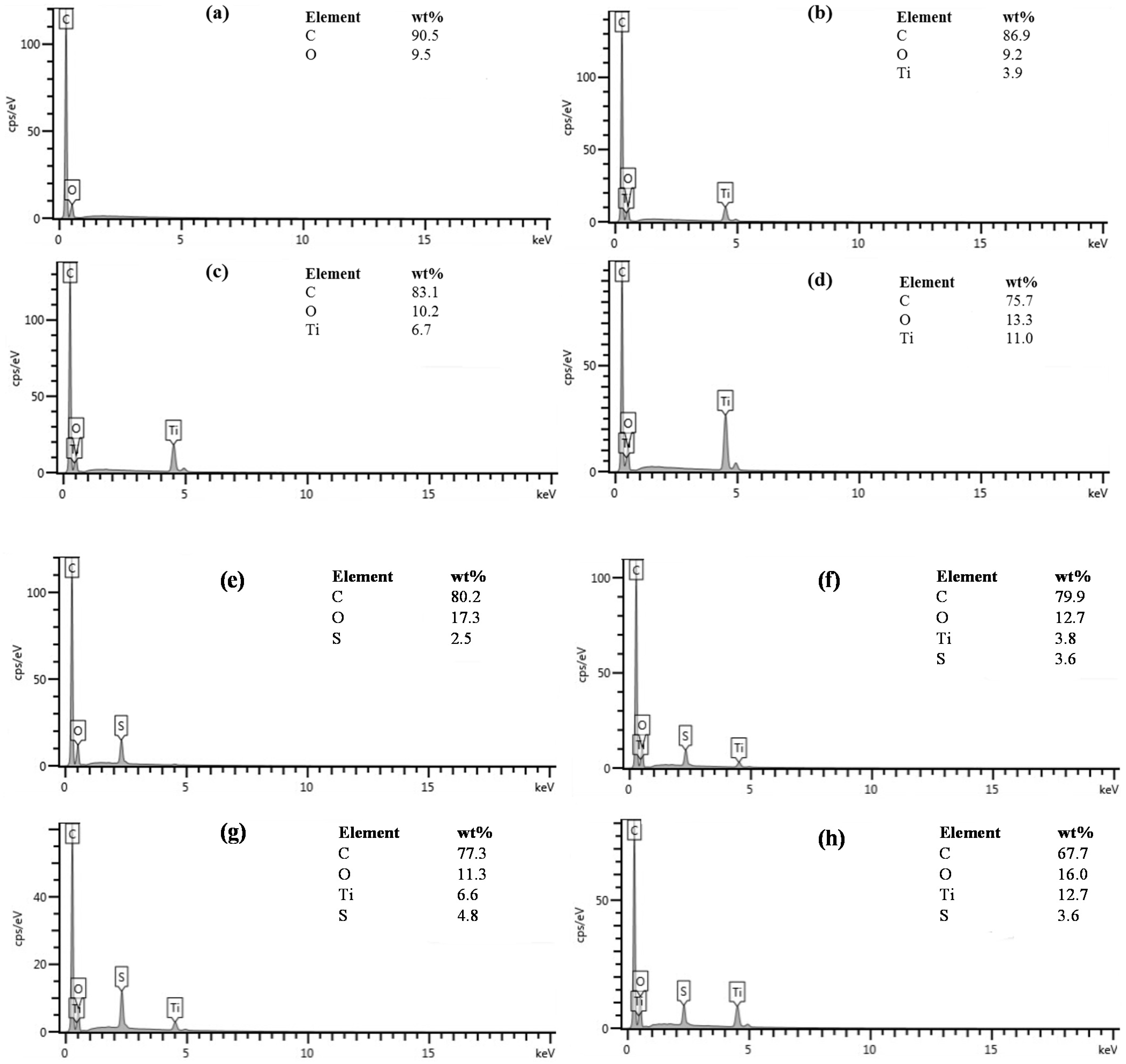
The energy-dispersive spectroscopy (EDS) spectra of the neat carbon and neat TiO2C composites are shown in parts (a) to (d) of Figure 3, and those of the carbon spheres and TiO2C after sulfonation are shown in parts (e) to (h) of Figure 3. The EDS spectrum of the carbon spheres contains only C and O peaks, whereas that of the composite samples contains the Ti peak, confirming that TiO2 was present in the samples. The elemental weight percent of C decreased with an increase in TiO2 loading. After sulfonating the carbon, the C, O, and S peaks are present in the spectrum (Figure 3e), indicating that the carbon spheres were neat and no impurities were detected in the sample. The spectra of the TiO2C_S acid catalysts [parts (f) to (h) of Figure 3] showed the presence of C, O, Ti, and S, and the elemental weight percentage of Ti increased with an increase in the loading percentage of TiO2. However, the weight percentage of C decreased with an increase in the loading percentage of TiO2. No other impurity elements were found in the prepared solid acid catalysts. The presence of S in all the solid acid catalysts indicated that the samples were successfully functionalised with sulfuric acid. Elemental composition analysis revealed that all the prepared acid catalysts contained sulfonic acid in the form of SO3H groups [23], further proving the presence of sulfonic groups, as indicated in Table 1. Wang et al. [14] also confirmed the presence of sulfonic groups on the surface of carbon materials after sulfonation. The TiO2C_S composites had C, O, Ti, and S, and their elemental weight percent of Ti increased with an increase in the loading percentage of Ti. However, the weight percent of C decreased with an increase in the loading percentage of Ti.

3.3. Chemical Analysis Using FTIR

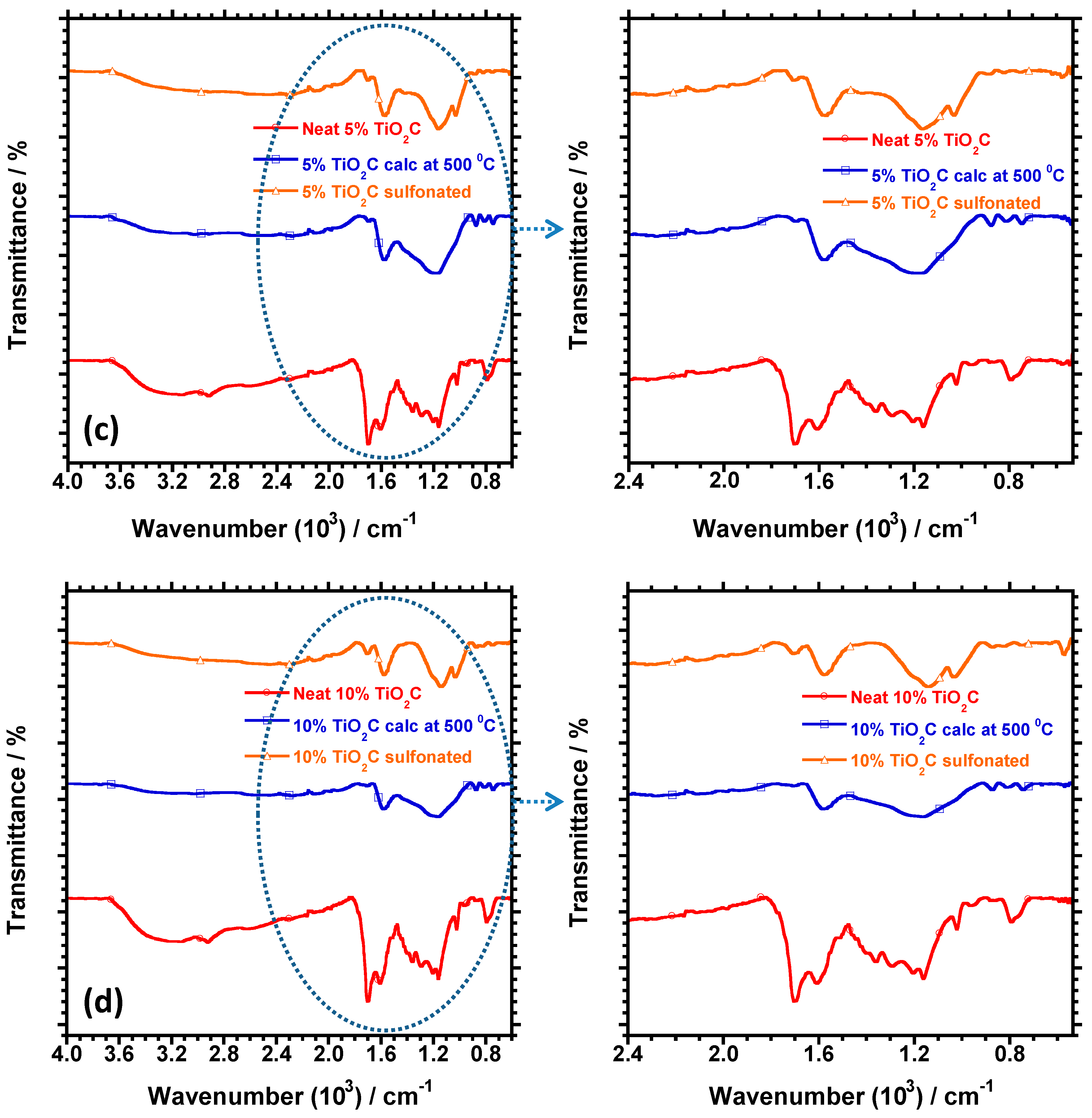
The FTIR spectra of the neat, calcined, and sulfonated carbon spheres are shown in Figure 4a. The presence of oxygen groups is demonstrated by the bands at 3000–3600 and 1710 cm−1, which were attributed to –OH stretching and C=O vibrations, respectively [3,24]. The 875–750 cm−1 band was assigned to the aromatic C–H group, and the presence of aromatic rings was confirmed by the band at 1620 cm−1, which was assigned to C=C vibrations [24]. Additional bands at 1180 and 1008 and 1106−1168 cm−1 were observed in the spectrum of the sulfonated carbon spheres. These bands were assigned to the symmetric stretching vibration of S=O groups, which are associated with the SO3 groups [25] and C=S stretching [26], respectively as shown in Figure 4a. These sulfonic peaks in the spectrum of the sulfonated carbon spheres indicate that -SO3H functional groups were attached to the carbon spheres. The FTIR spectra of the neat, calcined, and sulfonated 1%TiO2C, 5%TiO2C, and 10%TiO2C (Figure 4b–d) show bands at 1700 and 1200 cm−1, which were attributed to the C=O and C–O stretching of the carboxyl group [27]. A strong adsorption band of the S=O group at 1008 cm−1, which was associated with the SO3 groups, was observed.

3.4. Structural Characterisation Using XRD

The XRD patterns of the calcined carbon spheres and TiO2C composites are shown in Figure 5a. The XRD pattern of the neat carbon spheres showed broad peaks at 25° and 43°, which were indexed to the [002] and [100] characteristic phases of amorphous carbonaceous material, whereas the TiO2C sample which was loaded with the least dosage of TiO2 (1%TiO2C), was found to be amorphous, due to the effect of high concentration of the carbon which was present in the sample. The XRD pattern of the crystalline structure of the 5%TiO2C and 10%TiO2C composites had sharp peaks at 25.2°, 37.83°, 48.2°, 54.8°, 62.2°, and 70.2°, which were indexed to the [101], [004], [200], [105], [204], and [116] phases of anatase TiO2 [28]. After sulfonation, the peaks for the carbon spheres and 1%TiO2C shifted, as shown in Figure 5b. Moreover, the acid treatment (sulfonation) caused the [100] plane peak to disappear. The 5%TiO2C and 10%TiO2C composites were not affected by the sulfonation.

3.5. Catalytic Testing

3.5.1. Effect of Different Solvents on the Dehydration of Fructose into 5-HMF

Dehydration of fructose into 5-HMF was tested using different alcoholic solvents (such as isopropanol, ethanol, and methanol), water, and DMSO at 120 °C for 60 min (Table 2). All the alcoholic solvents produced a low 5-HMF yield of <12% on all the solid catalysts tested for this reaction. Water was also found to be an ineffective solvent. DMSO was the most effective solvent. The HMF yield was 84% for the carbon solid acid catalyst, 91% for 1%TiO2C_S, 92% for 5%TiO2C_S, and 95% for 10%TiO2C_S. Thus, the HMF dehydration increased as the TiO2 content increased. These results suggest that DMSO is a suitable solvent for use in the dehydration of fructose into 5-HMF when using TiO2C solid acid catalysts. DMSO acted both as a solvent and as a reaction mediator; hence a high dehydration of 5-HMF was achieved.
Table 3 shows a comparison of the TiO2C composite acid catalyst synthesised in this work with other catalysts reported in published works on dehydration of fructose into 5-HMF in DMSO using the microwave-assisted method. We found that our designed TiO2C_S acid catalysts produced the highest 5-HMF yield. The highest 5-HMF yield that we achieved at 120 °C, a temperature lower than those used in other studies, was 91% for 1%TiO2C_S and 92 and 95% for 5%TiO2C_S and 10%TiO2C_S, respectively. To our knowledge, this is the first report of the use of TiO2C_S composites as effective solid acid catalysts for the conversion of fructose into 5-HMF using the microwave-assisted method. De et al. [19] used mesoporous TiO2 nanomaterial to catalyse the dehydration of D-fructose into 5-HMF in DMSO solvent under microwave-assisted heating. This reaction was conducted at 130 °C for 2 min for a 49.2% 5-HMF yield was achieved. Dutta et al. [15] also used mesoporous TiO2 nanoparticles for the same reaction at 140 °C for 5 min and reported a yield of53.4%. Use of carbonaceous acid catalysts for this reaction achieved a 100% conversion of fructose and 90% 5-HMF yield at 160 °C for 1.5 h. Wang et al. [16] used carbon-based solid acid catalysts to catalyse the dehydration of fructose into 5-HMF at 130 °C for 1.5 h for a 5-HMF yield of about 91.2%. Hu et al. [18] explored a magnetic lignin-derived carbonaceous acid catalyst for the catalysed conversion of fructose into 5-HMF and achieved a 5-HMF yield of 81.1% with 100% fructose conversion.

3.5.2. Effect of Reaction Temperature on HMF Dehydration

The effect of reaction temperature on the catalytic transformation of fructose to HMF was carried out at 25, 60, 80, 100 and 120 °C. The reaction was conducted using 1%TiO2C_S, 5%TiO2C_S, 10%TiO2C_S, C_S solid acid catalysts and without the catalyst (non-catalytic reaction). The results are shown in Figure 6, which suggests that no 5-HMF was formed when the reaction was carried out in the absence of a catalyst on all the reaction temperatures that were studied. For the carbon solid acid catalyst and reaction temperature of 25 °C, the 5-HMF yield was <8%. When the temperature was raised to 60 °C, the 5-HMF yield slightly increased to 35%. At 80 °C, the 5-HMF yield improved to 71%. The highest 5-HMF yield of 85% was achieved at 120 °C. The effect of reaction temperature was also tested using the 1%TiO2C_S, 5%TiO2C_S, and 10%TiO2C_S solid acid catalysts. The 5-HMF yield was low when the reaction was conducted at 25 °C, then increased as the reaction temperature increased. The highest HMF yields of 91, 92, and 95% were achieved at 120 °C with the use of 1%TiO2C_S, 5%TiO2C_S, and 10%TiO2C_S solid acid catalysts, respectively. Thus, the best temperature for 5-HMF production using these composite catalysts was 120 °C. Compared to the performance of the carbon solid acid catalyst, an improved HMF yield was achieved with the use of 1, 5, and 10%TiO2C_S solid acid catalysts.

3.5.3. Effect of Reaction Time on 5-HMF Dehydration

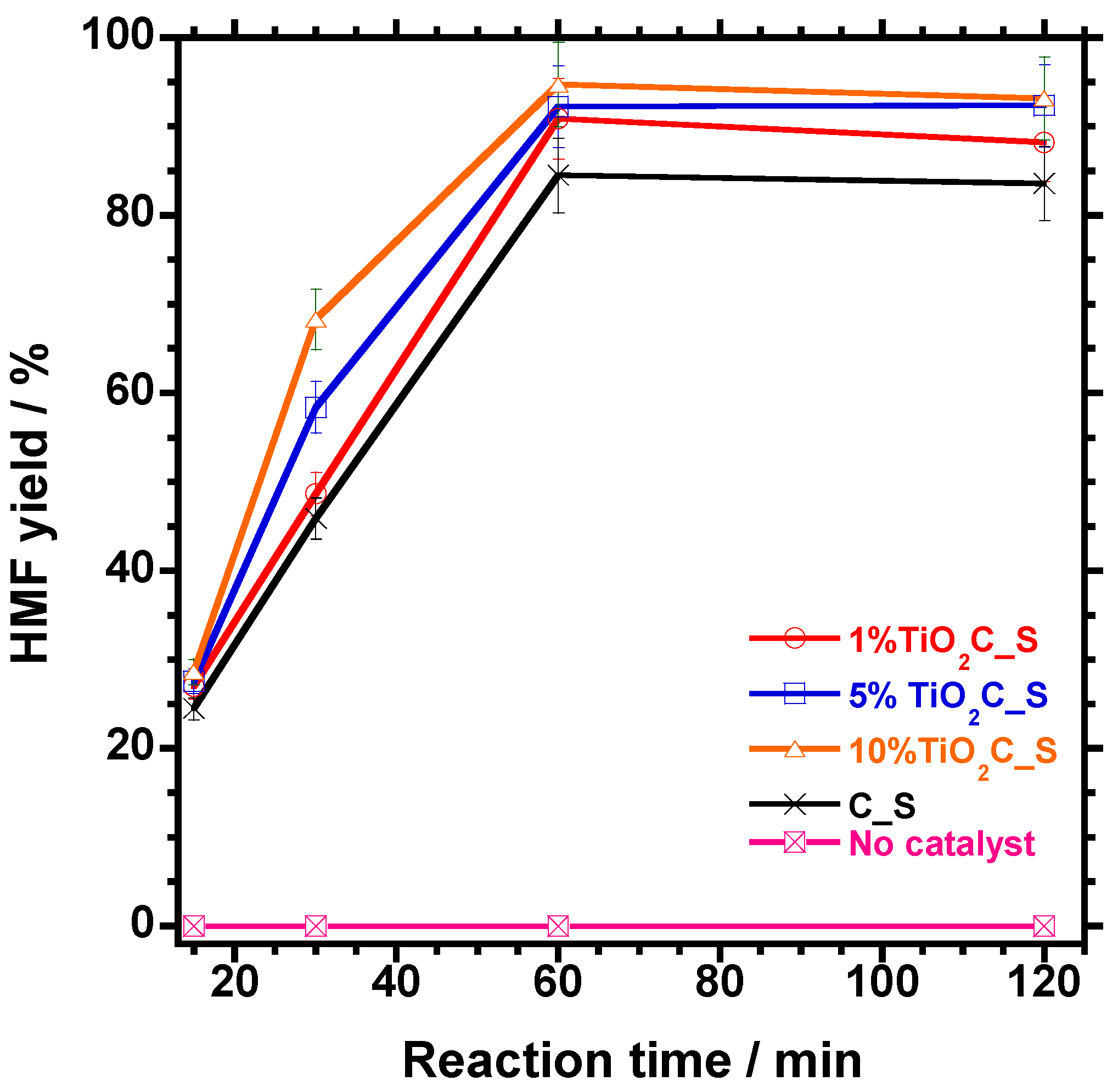
The effect of reaction time on the catalysed dehydration of fructose into 5-HMF was studied using different times of 15, 30, 60, and 120 min. The reaction was conducted using the prepared solid acid catalysts and no catalyst (non-catalytic reaction). The results are shown in Figure 7. No 5-HMF was formed when the reaction was carried out without a catalyst for all four reaction times. When the reaction was performed with the C_S solid acid catalyst, increasing the reaction time from 15 to 30 min improved the 5-HMF yield from 25% to 46%. The HMF dehydration increased rapidly to 85% after conducting the reaction for 60 min. However, performing the reaction for 120 min caused a slight drop in the 5-HMF yield to 83%. When conducting the dehydration reaction using 1%TiO2C_S, 5%TiO2C_S, and 10%TiO2C_S solid acid catalysts, increasing the reaction time from 15 to 30 min increased the 5-HMF yield from 27 to 49%, 28 to 58%, and 29 to 68%, respectively. Increasing the reaction time to 60 min significantly improved the 5-HMF yield to >90% for all the TiO2C composite acid catalysts. Finally, for a reaction time of 120 min, the HMF dehydration for 1%TiO2C_S, 5%TiO2C_S, and 10%TiO2C_S solid acid catalysts was calculated to be 88, 92, and 93%, respectively.

3.5.4. Effect of Catalyst Amount on HMF Dehydration

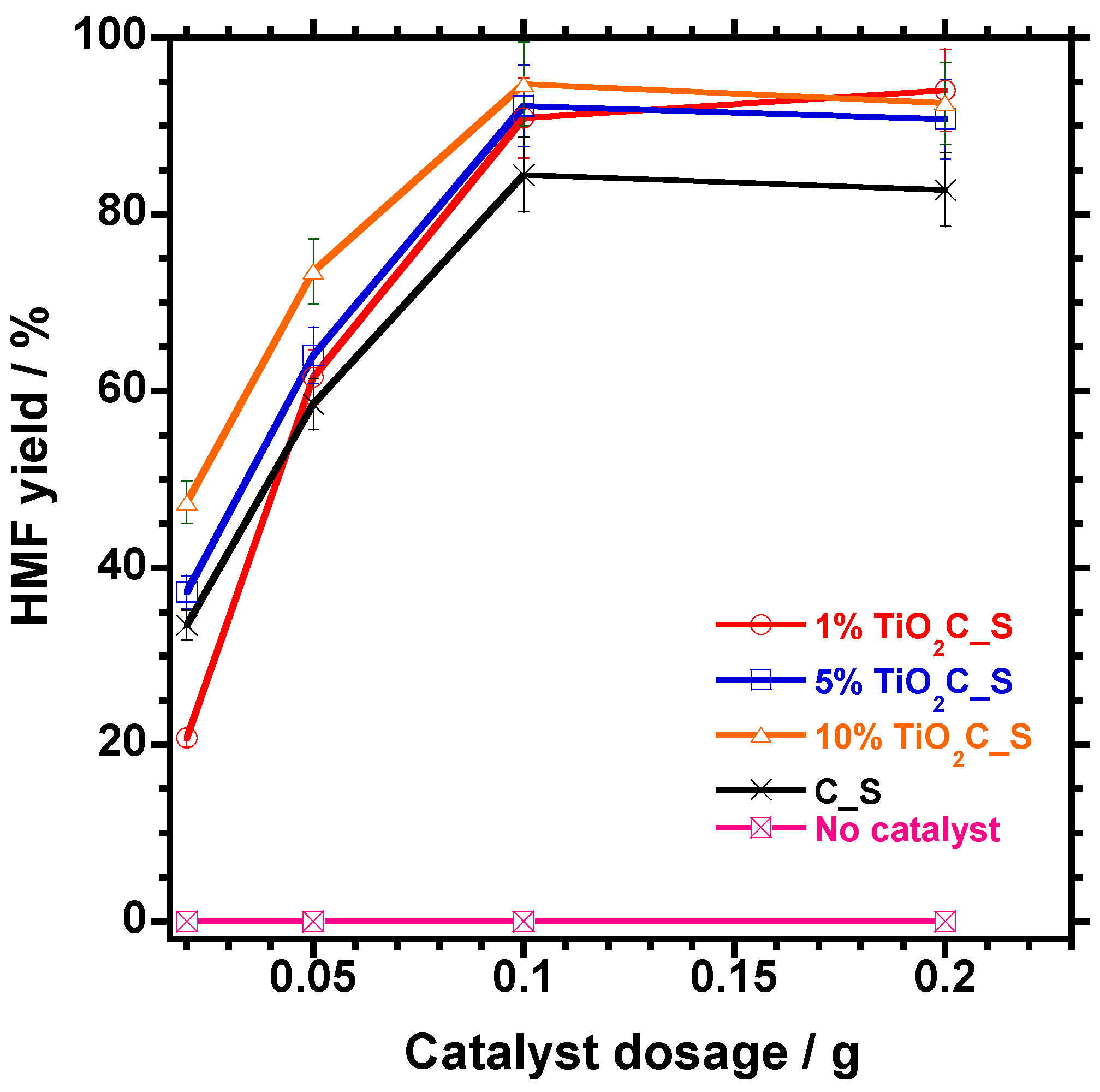
The effect of the amount of catalyst on the 5-HMF yield was studied, with the results presented in Figure 8. The reaction was carried out using catalyst dosages of 0.02, 0.05, 0.1, and 0.2 g. The results indicated that no 5-HMF was formed when this reaction was conducted in the absence of a catalyst on all the catalyst dosages that were studied. The 5-HMF yield increased from 34 to 59% when the amount of the C_S solid acid catalyst increased from 0.02 to 0.05 g under the same reaction conditions. An increase in the catalyst dosage to 0.1 g increased the 5-HMF yield to 85%. However, increasing the catalyst dosage to 0.2 g resulted in a reduction of the 5-HMF yield to 82%. The effect of catalyst concentration was also tested using the 1%TiO2C_S, 5%TiO2C_S, and 10%TiO2C_S solid acid catalysts. An increase in the catalyst dosage from 0.02 to 0.1 g drastically improved the 5-HMF yield of the 1%TiO2C_S, 5%TiO2C_S, and 10%TiO2C_S solid acid catalysts to 91, 92, and 95%, respectively. However, when the catalyst dosage increased to 0.2 g, the 5-HMF yield of the 5%TiO2C_S, and 10%TiO2C_S solid acid catalysts slightly decreased to 91 and 92% respectively, whereas in a case of the 1%TiO2C_S the 5-HMF yield increased to 93%. This decrease in 5-HMF dehydration at a high catalyst dosage for the 5%TiO2C_S and 10%TiO2C_S, could be attributed to the excess acid active sites that promote both the dehydration reaction and the formation of by-products such as humins [29]. The 5-HMF yields did not increase with an increase in catalyst dosage for the C_S, 5%TiO2C_S and 10%TiO2C_S solid acid catalysts.

3.5.5. Reusability of the Catalyst

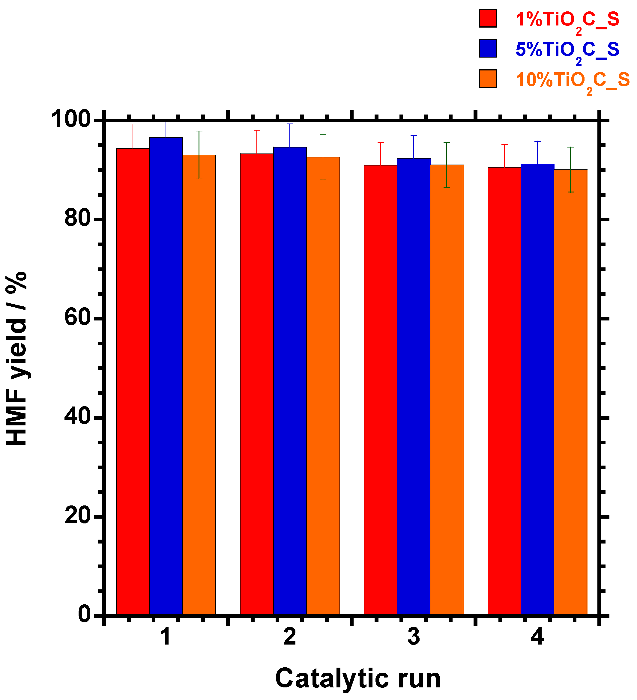
The reusability of the catalysts was studied, with the results presented in Figure 9. After the first run, the 5-HMF yields were 94, 97, and 93% for 1%TiO2C_S, 5%TiO2C_S, and 10%TiO2C_S, respectively. The 5-HMF yield slightly decreased after the fourth run. The 5-HMF yield of the 1%TiO2C_S and 10%TiO2C_S composite acid catalysts decreased by 3% and that of 5%TiO2C_S decreased by 5%. These results indicate that the TiO2C composite acid catalysts are highly stable and can be reused for the dehydration of fructose.

4. Conclusions

TiO2C solid acid catalysts were successfully prepared using the microwave-assisted method and then sulfonated with concentrated sulfuric acid. Microwave heating increases the rate of dehydration of fructose. The dehydration of fructose is closely related to the acidity of the catalyst. Among the solvents tested for use in the dehydration of fructose into 5-HMF, DMSO performed the best in terms of 5-HMF dehydration. The reaction temperature, reaction time, and catalyst dosage were found to have an effect on the 5-HMF dehydration. The solid acid catalysts synthesised in this work were highly stable and heterogeneous. Moreover, this study was the first time such TiO2C solid acid catalysts were used for dehydrating fructose into 5-HMF.

Author Contributions

M.M.S. design the concept and wrote the first draft of manuscript. R.M. went through manuscript and provided comments. S.S.R. critically reviewed and corrected the manuscript.

Funding

The authors are grateful to the Department of Science and Technology (DST, project no. HGERA8X) and the Council for Scientific and Industrial Research (CSIR, project no. HGER74p) of South Africa for financial support.

Conflicts of Interest

The authors declare no conflict of interest.

References

  1. Démolis, A.; Essayem, N.; Rataboul, F. Synthesis and applications of alkyl levulinates. ACS Sustain. Chem. Eng. 2014, 2, 1338–1352. [Google Scholar] [CrossRef]
  2. McNeff, C.V.; Nowlan, D.T.; McNeff, L.C.; Yan, B.; Fedie, R.L. Continuous production of 5-hydroxymethylfurfural from simple and complex carbohydrates. Appl. Catal. A Gen. 2010, 384, 65–69. [Google Scholar] [CrossRef]
  3. Qi, X.; Watanabe, M.; Aida, T.M.; Smith, R.L., Jr. Catalytical conversion of fructose and glucose into 5-hydroxymethylfurfural in hot compressed water by microwave heating. Catal. Commun. 2008, 9, 2244–2249. [Google Scholar] [CrossRef]
  4. Wang, J.; Ren, J.; Liu, X.; Xi, J.; Xia, Q.; Zu, Y.; Lu, G.; Wang, Y. Direct conversion of carbohydrates to 5-hydroxymethylfurfural using Sn-Mont catalyst. Green Chem. 2012, 14, 2506–2512. [Google Scholar] [CrossRef]
  5. Moreau, C.; Finiels, A.; Vanoye, L. Dehydration of fructose and sucrose into 5 hydroxymethylfurfural in the presence of 1-H-3-methyl imidazolium chloride acting both as solvent and catalyst. J. Mol. Catal. A Chem. 2006, 253, 165–169. [Google Scholar] [CrossRef]
  6. Asghari, F.S.; Yoshida, H. Acid catalysed production of 5-hydroxymethyl furfural from d-Fructose in Subcritical Water. Ind. Eng. Chem. Res. 2006, 45, 2163–2173. [Google Scholar] [CrossRef]
  7. Xu, H.; Miao, Z.; Zhao, H.; Yang, J.; Zhao, J.; Song, H.; Liang, N.; Chou, L. Dehydration of fructose into 5-hydroxymethylfurfural by high stable ordered mesoporous zirconium phosphate. Fuel 2015, 145, 234–240. [Google Scholar] [CrossRef]
  8. Jain, A.; Shore, A.M.; Jonnalagadda, S.C.; Ramanujachary, K.V.; Mugweru, A. Conversion Of fructose, glucose and sucrose to 5-hydroxymethyl-2-furfural over mesoporous zirconium phosphate catalyst. Appl. Catal. A Gen. 2015, 489, 72–76. [Google Scholar] [CrossRef]
  9. Kılıc, E.; Yılmaz, S. Fructose dehydration to 5-hydroxymethylfurfural over sulfated TiO2–SiO2, Ti-SBA-15, ZrO2, SiO2, and activated carbon catalysts. Eng. Chem. Res. 2015, 54, 5220–5225. [Google Scholar] [CrossRef]
  10. Wang, S.; Zhang, Z.; Liu, B. Catalytic conversion of fructose and 5-hydroxymethylfurfural into 2,5-Furandicarboxylic acid over a recyclable Fe3O4−CoOx magnetite nanocatalyst. ACS Sustain. Chem. Eng. 2015, 3, 406–412. [Google Scholar] [CrossRef]
  11. Yang, Z.; Qi, W.; Huang, R.; Fang, J.; Su, R.; He, Z. Functionalized silica nanoparticles for conversion of fructose to 5-hydroxymethylfurfural. Chem. Eng. J. 2016, 296, 209–216. [Google Scholar] [CrossRef]
  12. Morales, G.; Paniagua, M.; Melero, J.A.; Iglesias, J. Efficient production of 5-ethoxymethylfurfural from fructose by sulfonic mesostructured silica using DMSO as co-solvent. Catal. Today 2017, 279, 305–316. [Google Scholar] [CrossRef]
  13. Hu, B.; Wang, K.; Wu, L.; Yu, S.H.; Antonietti, M.; Titirici, M.M. Engineering carbon materials from the hydrothermal carbonization process of biomass. Adv. Mater. 2010, 22, 813–828. [Google Scholar] [CrossRef] [PubMed]
  14. Wang, J.; Zhang, Y.; Wang, Y.; Zhu, L.; Cui, H.; Yi, W. Catalytic fructose dehydration to 5-hydroxymethylfurfural over sulfonated carbons with hierarchically ordered pores. J. Fuel Chem. Technol. 2016, 44, 1341–1348. [Google Scholar] [CrossRef]
  15. Zhao, J.; Zhou, C.; He, C.; Dai, Y.; Jia, X.; Yang, Y. Efficient dehydration of fructose to 5 hydroxymethylfurfural over sulfonated carbon sphere solid acid catalysts. Catal. Today 2016, 264, 123–130. [Google Scholar] [CrossRef]
  16. Wang, J.; Xu, W.; Ren, J.; Liu, X.; Lu, G.; Wang, Y. Efficient catalytic conversion of fructose into hydroxymethylfurfural by a novel carbon-based solid acid. Green Chem. 2011, 13, 2678–2681. [Google Scholar] [CrossRef]
  17. Guo, F.; Fang, Z.; Zhou, T.J. Conversion of fructose and glucose into 5-hydroxymethylfurfural with lignin-derived carbonaceous catalyst under microwave irradiation in dimethyl sulfoxide–ionic liquid mixtures. Bioresour. Technol. 2012, 112, 313–318. [Google Scholar] [CrossRef] [PubMed]
  18. Hu, L.; Tang, X.; Wu, Z.; Linc, L.; Xu, J.; Xu, N.; Dai, B. Magnetic lignin-derived carbonaceous catalyst for the dehydration of fructose into 5-hydroxymethylfurfural in dimethyl sulfoxide. Chem. Eng. J. 2015, 263, 299–308. [Google Scholar] [CrossRef]
  19. De, S.; Dutta, S.; Patra, A.K.; Bhaumik, A.; Saha, B. Self-assembly of mesoporous TiO2 nanospheres via aspartic acid templating pathway and its catalytic application for 5-hydroxymethyl-furfural synthesis. J. Mater. Chem. 2011, 21, 17505–17510. [Google Scholar] [CrossRef]
  20. Dutta, S.; De, S.; Patra, A.K.; Sasidharan, M.; Bhaumik, A.; Saha, B. Microwave assisted rapid conversion of carbohydrates into 5-hydroxymethylfurfural catalysed by mesoporous TiO2 nanoparticles. Appl. Catal. A Gen. 2011, 409–410, 133–139. [Google Scholar] [CrossRef]
  21. Tamborini, L.H.; Casco, M.E.; Militello, M.P.; Silvestre-Albero, J.; Barbero, C.A.; Acevedo, D.F. Sulfonated porous carbon catalysts for biodiesel production: Clear effect of the carbon particle size on the catalyst synthesis and properties. Fuel Process. Technol. 2016, 149, 209–217. [Google Scholar] [CrossRef]
  22. Liu, X.Y.; Huang, M.; Ma, H.L.; Zhang, Z.Q.; Gao, J.M.; Zhu, Y.L.; Han, X.J.; Guo, X.Y. Preparation of a carbon-based solid acid catalyst by sulfonating activated carbon in a chemical reduction process. Molecules 2010, 15, 7188–7196. [Google Scholar] [CrossRef] [PubMed]
  23. Hou, Q.; Li, W.; Ju, M.; Liu, L.; Chen, Y.; Yang, Q. One-pot synthesis of sulfonated graphene oxide for efficient conversion of fructose into HMF. RCS Adv. 2016, 16, 104016–104024. [Google Scholar] [CrossRef]
  24. Qi, X.; Guo, H.; Li, L.; Smith, R.L., Jr. Acid-catalyzed dehydration of fructose into 5-hydroxymethylfurfural by cellulose derived amorphous carbon. ChemSusChem 2012, 5, 2215–2220. [Google Scholar] [CrossRef] [PubMed]
  25. Sevilla, M.; Fuertes, A.B. The production of carbon materials by hydrothermal carbonization of cellulose. Carbon 2009, 47, 2281–2289. [Google Scholar] [CrossRef] [Green Version]
  26. Sun, Y.; Zhao, J.; Wang, J.; Tang, N.; Zhao, R.; Zhang, D.; Guan, G.; Li, K. Sulfur doped millimetre sized microporous activated carbon spheres derived from sulfonated poly(styrene-devinylbenzene) for CO2 capture. J. Phys. Chem. C 2017, 121, 10000–10009. [Google Scholar] [CrossRef]
  27. Rao, C.N.R. Contribution to the infrared spectra of organosulphur compounds. Can. J. Chem. 1964, 42, 36–42. [Google Scholar] [CrossRef]
  28. Yu, D.; Bo, B.; Yunhua, H. Fabrication of TiO2@yeast-carbon hybrid composites with the raspberry like structure and their synergistic adsorption photocatalysis performance. J. Nanomater. 2013, 2013, 851417. [Google Scholar] [CrossRef]
  29. Kansal, S.K.; Sood, S.; Umar, A.; Mehta, S.K. Photocatalytic degradation of Eriochrome Black T dye using well-crystalline anatase TiO2 nanoparticles. J. Alloys Compd. 2013, 581, 392–397. [Google Scholar] [CrossRef]
Figure 1. SEM low magnification images of (a) neat C, (b) neat 1%TiO2C, (c) neat 5%TiO2C, (d) neat 10%TiO2C, (e) C_S solid acid catalyst, (f) 1%TiO2C_S solid acid catalyst, (g) 5%TiO2C_S solid acid catalyst, and (h) 10%TiO2C_S solid acid catalyst.
Catalysts 09 00126 g001
Figure 2. SEM high magnification images of (a) C_S solid acid catalyst, (b) 1%TiO2C_S solid acid catalyst, (c) 5%TiO2C_S solid acid catalyst, (d) 10%TiO2C_S solid acid catalyst and (e) sulfonated TiO2.
Catalysts 09 00126 g002
Figure 3. EDS spectra and elemental composition of (a) neat C, (b) neat 1%TiO2C, (c) neat 5% TiO2C, (d) neat 10% TiO2C, (e) C_S solid acid catalyst, (f) 1%TiO2C_S solid acid catalyst, (g) 5% TiO2C_S solid acid catalyst, and (h) 10% TiO2C_S solid acid catalyst.
Catalysts 09 00126 g003
Figure 4. FTIR spectra of neat, calcined and sulfonated (a) carbon, (b) 1%TiO2C, (c) 5%TiO2C, and (d) 10%TiO2C.
Catalysts 09 00126 g004aCatalysts 09 00126 g004b
Figure 5. XRD results for carbon spheres and TiO2C composites (a) that were calcined at 500 °C and (b) after sulfonation.
Catalysts 09 00126 g005
Figure 6. Effect of reaction temperature on fructose dehydration into HMF using sulfonated carbon and TiO2C composite catalysts in DMSO solvent.
Catalysts 09 00126 g006
Figure 7. Effect of reaction time on the dehydration of fructose into HMF in DMSO solvent.
Catalysts 09 00126 g007
Figure 8. Effect of catalyst dosage on the dehydration of fructose into HMF in DMSO solvent.
Catalysts 09 00126 g008
Figure 9. Recycling of the 1%TiO2C_S, 5%TiO2C_S, and 10%TiO2C_S acid catalysts used in the dehydration of fructose into HMF. Conditions: reaction time = 60 min, reaction temperature = 120 °C, catalyst concentration = 0.1 g, amount of fructose = 0.5 g, volume of DMSO = 6 mL).
Catalysts 09 00126 g009
Table 1. Textural properties and hot filtration results of carbon spheres and TiO2C nanocomposites.
Catalyst before SulfonationCatalyst after Sulfonation
SBET
(m2/g)
Vp
(cm3/g)
SBET
(m2/g)
Vp
(cm3/g)
Sulfonic Groups
(m·molg−1) a
C517-C_S167-1.34
1%TiO2C4130.261%TiO2C_S830.071.46
5%TiO2C2730.135%TiO2C_S610.041.55
10%TiO2C2020.1010%TiO2C_S590.031.49
C: Carbon; SBET: Surface Area; Vp: Pore Volume; S_: Sulfonated; a Attained by titration with NaOH.
Table 2. Dehydration of fructose in different solvents.
CatalystHMF Dehydration (%) [UV-Vis at the Measured Absorbance of 284 nm]
MethanolDI WaterEthanolIsopropanolDMSO
C3511184
1%TiO2C364991
5%TiO2C316092
10%TiO2C04121195
Reaction conditions: Substrate, fructose; catalyst amount, 0.1 g; temperature, 120 °C; time, 60 min.
Table 3. Comparison of results of the dehydration of fructose (substrate) into 5-HMF in DMSO using carbonaceous and TiO2-based solid acid catalysts.
CatalystCatalyst Mass
(g)
Substrate Mass
(g)
T
(°C)
Time
(min)
5-HMF Yield (%)Ref.
Uv-Vis aHPLC b
C_S0.10.51206084-This work
1%TiO2C_S0.10.51206091-This work
5%TiO2C-S0.10.51206092-This work
10%TiO2C_S0.10.51206095-This work
TiO20.050.1130249.547.8[19]
TiO20.10.05140553.4-[20]
CS0.10.516090-90[15]
C0.40.513090-91.2[16]
Magnetic lignin-derived carbon (MLC)-SO3H0.050.113040-81.1[18]
a 5-HMF dehydration was calculated by UV-vis at the measured absorbance of 284 nm; b 5-HMF dehydration measured by HPLC.