Abstract
Combinations of TiO2 photocatalysts and various adsorbents have been extensively investigated for eliminating volatile organic compounds (VOCs) at low concentrations. Herein, TiO2 and porous glass cloth composites were prepared by acid leaching and subsequent TiO2 dip-coating of the electrically applied glass (E-glass) cloth, and its adsorption and photocatalytic ability were investigated. Acid leaching increased the specific surface area of the E-glass cloth from 1 to 430 m2/g while maintaining sufficient mechanical strength for supporting TiO2. Further, the specific surface area remained large (290 m2/g) after TiO2 coating. In the photocatalytic decomposition of gaseous 2-propanol, the TiO2-coated porous glass cloth exhibited higher adsorption and photocatalytic decomposition ability than those exhibited by the TiO2-coated, non-porous glass cloth. The porous composite limited desorption of acetone, which is a decomposition intermediate of 2-propanol, until 2-propanol was completely decomposed to CO2. The CO2 generation rate was affected by the temperature condition (15 or 35 °C) and the water content (2 or 18 mg/L); the latter also influenced 2-propanol adsorption in photocatalytic decomposition. Both the conditions may change the diffusion and adsorption behavior of 2-propanol in the porous composite. As demonstrated by its high adsorption and photocatalytic ability, the composite (TiO2 and porous glass cloth) effectively eliminates VOCs, while decreasing the emission of harmful intermediates.
Keywords:
photocatalyst; microporous material; composite; adsorption; air purification; TiO2; porous glass 1. Introduction
Indoor air pollution by volatile organic compounds (VOCs) is considered to be a serious health problem. Construction materials emit various VOCs, including formaldehyde, acetaldehyde, toluene, xylene, hexane, acetone, and 2-propanol, which can cause the sick building syndrome even at VOC concentrations lower than 1 ppm [1]. Further, the VOC concentrations in the work spaces are strictly limited to prevent health damage from prolonged exposure. However, the imposed concentration limits of the major solvents are in the range of 10–103 ppm [2]. Titanium dioxide (TiO2) photocatalysts have been extensively investigated in VOC decomposition because of their strong oxidation abilities under ultraviolet (UV) irradiation and because of their ability to decompose various organic compounds [3,4,5,6]. However, the VOC decomposition rates are observed to be insufficient at considerably low concentrations because the photocatalytic decomposition reaction tends to be diffusion controlled under such conditions [7].
A promising solution to this problem is to combine TiO2 with an appropriate adsorbate material. Further, the proposed mechanism of VOC elimination by composites can be given as follows. The concentration of VOC molecules can be obtained based on the adherence of VOC molecules in bulk air to the adsorbate surface. The VOC molecules in bulk air are concentrated on the adsorbate surface by adsorption. The adsorbed molecules are diffused to the vicinity of the TiO2 surface and are photo-catalytically decomposed by TiO2 [8,9]. The adsorbate is a porous material, including activated carbon [9,10], zeolite [9,11,12], silica gel [13], or mesoporous silica [14,15]. The composites require a free-standing structure for maintaining sufficient mechanical strength in practical applications. Further, because it is generally difficult to prepare the composites from porous adsorbates, they are used in powder form or are supported on another substrate [12]. Porous glass is an adsorbate candidate exhibiting sufficient mechanical strength for TiO2 support. Thus, a composite photocatalyst of TiO2 and porous glass exhibits superior photocatalytic activity to powder TiO2, or non-porous composite photocatalyst in case of gaseous and aqueous systems [16,17,18,19].
The electrically applied glass (E-glass) fiber is a mass-produced glass fiber with low alkaline metal content. E-glass fiber and its cloth are primarily used to form the fiber-reinforced plastics. The typical composition of E-glass fiber is 52–62 wt % SiO2, 16–25 wt % CaO, 12–16 wt % Al2O3, 0–10 wt % B2O3, and 0–5 wt % MgO, along with small amounts of alkaline metal oxides (TiO2 and Fe2O3) and fluorides [20]. When the E-glass fiber is corroded in an acid solution [21,22], a porous structure is formed. The pores are formed by the dissolution of Al2O3, B2O3, and the ions of alkaline metals and alkali earth metals, leaving the SiO2 structure. The acid-leached E-glass fiber and cloth are the porous materials that had been investigated in previously conducted studies [23,24,25]. The properties of porous glass cloth, such as the high adsorption capacity for VOCs, high optical transparency, low weight, and sufficient mechanical strength, are considered to be advantageous for photocatalyst support. Very low alkali metal content is another advantage because the diffusion of alkaline metal ions from the glass substrate to the TiO2 photocatalyst deteriorates the photocatalytic activity of TiO2 [26,27]. Kitamura et al. prepared air filters by combining the TiO2 photocatalyst and the porous glass fiber cloth that was prepared by acid leaching [25]. They further examined the filter’s ability to eliminate gaseous formaldehyde; however, they did not measure the concentration of the decomposition products. Therefore, they could not discuss the contributions of adsorption and photocatalytic decomposition in the elimination process.
In this study, a composite material was fabricated from the TiO2 photocatalyst and porous glass fiber cloth; further, its adsorption and photocatalytic decomposition ability has been examined with respect to gaseous air-diluted 2-propanol. The TiO2–porous glass cloth composite was prepared by acid leaching the glass cloth and by subsequently dip-coating it using TiO2. The pore formation process was investigated by observing the microstructure, analyzing the chemical composition, and measuring the N2 adsorption of the acid-leached glass cloth. Further, the effects of TiO2 loading on the composite properties were also investigated. Subsequently, the adsorption and photocatalytic properties of the TiO2-coated porous glass cloth were investigated using 300 ppm of gaseous 2-propanol. The concentration changes in the 2-propanol, acetone as an intermediate oxidative product of 2-propanol, and CO2 as a final product of 2-propanol decomposition were measured during the adsorption and photocatalytic decomposition. Further, the effects of temperature and water content on the adsorption and photocatalytic decomposition abilities of the composite were also investigated because these factors affect the photocatalytic decomposition rates of 2-propanol [28,29,30,31] and acetone [32,33], and because they may affect the adsorption and diffusion of organic molecules in the porous glass. Finally, based on the experimental results, we discuss the adsorption and photocatalytic decomposition mechanisms of the TiO2-coated porous glass cloth.
2. Results and Discussion
2.1. Microstructure Analysis and Mechanical Strength Test
The micro-structural change of the E-glass cloth that was prepared by acid leaching and TiO2 coating was investigated using field emission scanning electron microscopy (FE–SEM). Hereafter, the unleached and leached samples are referred to as the non-porous and porous glass samples, respectively. Panels (a–c) of Figure 1 denote the cross-sectional images of the non-porous and porous glass fibers comprising cloth samples. After leaching for 1 h, the structure of the glass fibers changed from uniform and dense with no pores (Figure 1a), to a dense core surrounded by a porous surface layer with a thickness of 2–3 µm (Figure 1b). After 3 h of leaching, the glass fiber was observed to become completely porous. The SEM images indicate that the porous structure was formed from the surface to the center as the leaching time increased, as previously reported by Tanaka et al. [24]. Panels (d–f) of Figure 1 denote the side views of the non-porous and porous glass fibers. A larger number of cracks developed in the porous fibers when compared to that in the non-porous fibers. The cracks that were observed on the 1-h leached fibers were mainly observed to be perpendicular to the fiber elongation direction and propagated only in the porous layer. This indicated that the cracks were generated by the tensile stress in the porous layer. During the drying process, the generation of strong capillary forces in the porous structure could shrink the porous surface layer. The different shrinkage ratios between the core and the porous layer could further result in crack generation. In contrast, the cracks on the 3-h leached fibers progressed along the fiber elongation direction and near the fiber center. Further, the mechanism of crack generation differed between the samples that were prepared after 1 and 3 h of leaching. The residual stress that was derived from the fiber spinning process may explain this type of crack generation, as will be discussed in our subsequent report. Despite the generation of clacking by acid leaching, the flexibility of the porous glass cloth was maintained at a high level. When the 3-h leached glass cloth was curved with a curvature radius of 3 mm, the glass cloth did not break; further, its form was recovered without any deformation. Panels (g–i) of Figure 1 denote the side views of the TiO2-coated fibers. Agglomerates of the TiO2 nanoparticles are observed on the surfaces, and the coating is observed to be in-homogeneous. Because the glass cloth samples have high fiber density, homogeneous coating of each fiber by dip-coating the cloth sample would be difficult. Further, the sampling process before FE–SEM observation can cause some damage to the TiO2 coating. Figure S1 depicts the surface and fracture cross-section of TiO2 coating on the porous glass cloth at a position where plenty of TiO2 is loaded and where only little sample damage is observed. The TiO2 coating exhibited a porous structure, and VOCs can penetrate the coating.
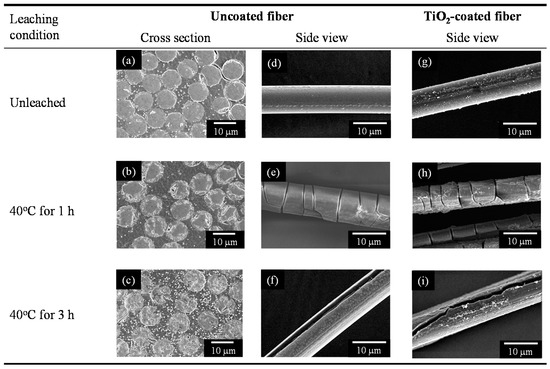
Figure 1.
SEM images of the non-porous and porous glass fibers before (left and center panels) and after (right panel) TiO2 coating.
2.2. Crystalline Phase of TiO2
The TiO2-coated glass cloth samples, and the TiO2 powder sample that was prepared from TiO2 suspension used in the dip-coating process, were ground with a pestle in an agate mortar, and their X-ray diffraction (XRD) patterns were measured. Figure 2 depicts the XRD patterns of the aforementioned samples. The TiO2 suspension comprised anatase (TiO2) nanoparticles and solvent; therefore, the TiO2 powder sample prepared from the TiO2 suspension exhibited anatase peaks (Figure 2a). The crystalline size that was estimated from Scherrer’s equation using 101 reflection is 6.9 nm. The TiO2-coated non-porous glass cloth exhibited no anatase peak (Figure 2b). This can be attributed to the lesser amounts of TiO2, and will be explained in the following elemental analysis in Section 2.3. The broad peaks that can be observed at around 26° denote the glass halo, whereas the peaks that can be observed at around 42° denote the graphite oxide generated by incomplete organic molecule combustion. The TiO2-coated 3-h leached porous glass cloth did not exhibit the strongest 101 reflection of anatase because it was overwrapped with glass halo at around 24° (Figure 2c). However, the 220, 105, 211, and 204 reflections of anatase can be clearly observed. Based on these results, the TiO2 on the porous sample was observed to be in the anatase form. Further, the TiO2 on the non-porous sample was also in the anatase form because it was prepared in the same manner as the porous sample. It indicates that the use of black light lump (center wavelength: 365 nm), in the following photocatalytic decomposition experiments, is suitable for the photo-excitation of this composite because anatase exhibits a bandgap of 3.2 eV (388 nm) [34].
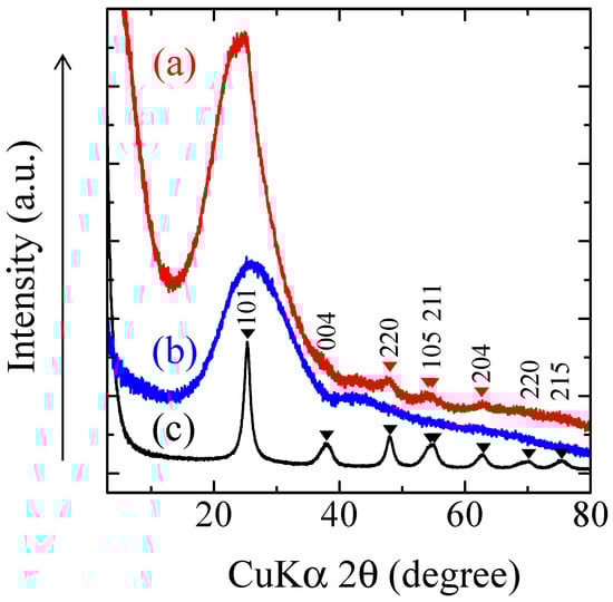
Figure 2.
Powder X-Ray diffraction (XRD) pattern of the ground samples: (a) dried and heated TiO2 suspension; (b) TiO2-coated non-porous glass cloth; and (c) TiO2-coated porous glass cloth. hkl are reflection indices of anatase.
2.3. Chemical Composition Analysis
Figure 3 depicts the chemical compositions of the non-porous and porous glass cloths that have been estimated using the X-ray fluorescence (XRF) measurements. In this figure, the porous cloths were obtained after leaching for 1, 3, and 12 h. While estimating the compositions of the 3- and 12-h leached glass cloths, sodium oxide was assumed to be zero because the sample pellets were prepared using Na2CO3. With an increase in leaching time, the composition ratios of the alkali earth metal oxides, boron oxide, alkali metal oxides, and alumina decreased, whereas the silica content was maintained to be almost constant. The leaching of the non-silica components from the glass fiber resulted in the formation of the observed microporous structures in the glass cloths Panels (b,c,e,f) of Figure 1. The composition almost ceased to change after 3 h of leaching (the time of core disappearance in the acid-leached fibers).
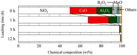
Figure 3.
Chemical compositions of the non-porous (0-h leaching time) and porous glass cloths estimated from the X-ray fluorescence (XRF) measurements. The “Others” category includes TiO2, Na2O, K2O, Fe2O3, and SrO.
Further, the TiO2 contents in the TiO2-coated non-porous and porous glass cloths were evaluated using XRF. Figure 4 plots the TiO2 content and weight loss of the glass cloth as functions of the acid leaching time. The weight loss of the glass cloth was calculated as follows:
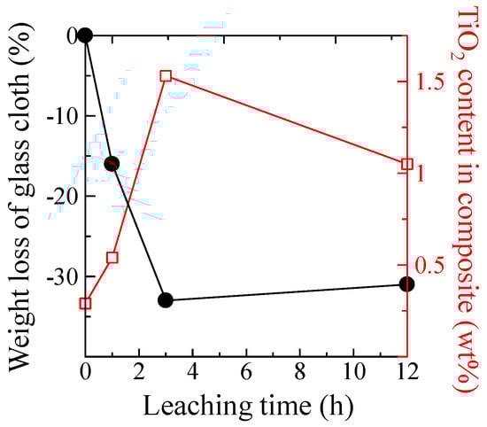
Figure 4.
TiO2 content in the TiO2-coated porous glass cloth (open squares) and weight loss of the porous glass cloth (filled circles) versus the acid leaching time.
Both the TiO2 loading amount and weight loss of the glass cloth increased at the maximum leaching time of 3 h. Even if the TiO2 loading amount was unaffected by the leaching time, the TiO2 composition ratio was observed to increase because of the weight loss of the glass cloth. However, the increase in the TiO2 composition ratio exceeded the expected value corresponding to this weight loss, demonstrating the remaining factors that were responsible for this increase in TiO2 composition ratio. As will be discussed subsequently, the TiO2 particles cannot penetrate the pores in the glass fiber structure; therefore, the increased volume of pores cannot be explained by the increased loading amount of TiO2. However, the large cracks that are observed in the SEM images (Figure 1e,f) are considered to be the likely support sites of the TiO2 particles in the dip-coating process. Further, the pore formation can also increase the TiO2 content by increasing the surface roughness or the wettability of the glass surface. In contrast, the increase in leaching time from 3 to 12 h decreases the TiO2 amount. However, the factors that can affect the TiO2 loading, weight loss, cracking, and surface conditions were not significantly altered in this time range. Therefore, the loading amount of TiO2 was observed to be saturated rather than decreased.
2.4. N2 Adsorption
Figure 5 depicts the N2 adsorption and desorption isotherms of the non-porous and the 3-h leached porous glass cloths before and after TiO2 coating. The non-porous samples (Figure 5a) yielded a type III adsorption isotherm, confirming the absence of micrometer- or nanometer-sized pores [35]. However, the porous samples (Figure 5b) yielded a type I adsorption isotherm, indicating the existence of nanometer-sized pores (<2 nm) [35]. The sample that was prepared in an extended leaching time (12 h) yielded a type I adsorption isotherm, indicating that the pore size will not be significantly changed by prolonging the leaching time. Figure 6 plots the specific surface areas (Sg) of the TiO2-coated and uncoated glass cloth samples versus the acid leaching time. The Sg values of both the samples increased up to approximately 4 h of leaching time and remained almost constant thereafter, indicating that the microporous structure was completely formed after 4 h of leaching. However, in the SEM images, the fiber core disappeared after 3 h of leaching (Figure 1c), implying that the microporous structure continued to evolve after the fiber center was subjected to acid leaching. After the disappearance of the core, Sg was probably increased by the leaching of the non-silica components that remained in the porous glass cloth and by the precipitation of silica gel in the pores. The latter process is typically observed during the leaching of the phase-separated borosilicate glasses [36,37].
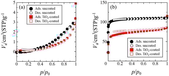
Figure 5.
Adsorption (Ads.) and desorption (Des.) isotherms of (a) a non-porous glass cloth and (b) a porous glass cloth before and after TiO2 coating.
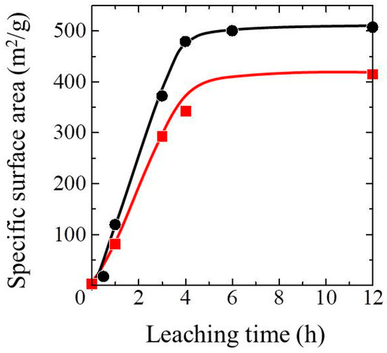
Figure 6.
Specific surface area versus leaching time of the TiO2-coated porous glass cloths (squares) and the uncoated porous glass cloth (circles).
As depicted in Figure 5b, the TiO2 coating reduced the adsorbed/desorbed N2 in the low pressure region or the isotherm. This decrease corresponds to the lower Sg value of the TiO2-coated samples when compared to that of the uncoated samples depicted in Figure 5. This decrease cannot be ascribed to the filling of nanometer-sized pores by TiO2 particles because even the primary particle size of TiO2 (6 nm) is considerably larger than the estimated pore diameter (<2 nm). To elucidate the reason that the Sg decreased during the TiO2 coating process, we investigated the manner in which heat treatment after dip-coating affected the Sg of the samples. The porous glass cloth that was prepared by 3 h of leaching was subjected to the same heat treatment as that used in the dip-coated samples (300 °C for 2 h), and its measured Sg was compared with that of the samples obtained before heat treatment. The heat treatment decreased the Sg from 370 to 200 m2/g, indicating that heating was mainly responsible for the loss of Sg in the TiO2-coated sample. To verify the effects of coating and heating on the porous properties, we investigated the pore-size distribution in the samples. Figure S2 depicts the adsorption isotherms of the uncoated and TiO2-coated porous glass cloths and their pore-size distributions estimated by Saito–Foley fitting [38,39]. The majority of the pores were observed to be less than 1 nm in diameter, and the TiO2 coating and heating process reduced the volume of the large pores. The reduced Sg and enlarged pores in the heat-treated sample may have arisen from dehydration condensation of the silanol groups on the surface of the pores [40]. However, because the subsequent heat treatment ensured that a high specific surface area of the TiO2-coated glass cloth was retained, the organic-molecule adsorption ability of the TiO2-coated sample should not have been significantly degraded.
2.5. Adsorption and Photocatalytic Ability of 2-Propanol
First, the adsorption and photocatalytic decomposition abilities of the TiO2-coated porous glass cloth, that was prepared by 3 h of leaching, and the TiO2-coated non-porous glass cloth were compared at 15 °C and a low water content (2 mg/L). Figure 7a plots the 2-propanol concentration versus time under dark conditions. The non-porous sample gradually reduced the concentration of gaseous 2-propanol during the initial 60 min, whereas the porous sample rapidly reduced the 2-propanol concentration within the initial 10 min, reducing it to lower than the detection limit in 20 min. These results indicate the strong absorbency of the porous sample for gaseous 2-propanol. The panels (b,c) of Figure 7 depict the temporal changes of 2-propanol concentration under UV light irradiation for the TiO2-coated non-porous and porous glass cloths, respectively, after the adsorption experiment is conducted in dark conditions. Further, the photocatalytic oxidation decomposition of gaseous 2-propanol tends to desorb acetone from the TiO2 surface; consequently, acetone is formed as a typical decomposition intermediate of this process [33]. The acetone concentration that was desorbed from the TiO2-coated non-porous glass cloth increased to its maximum at 2.5 h of irradiation time and gradually decreased. Meanwhile, the CO2 concentration monotonically increased with the UV light irradiation time. However, acetone was not detected from the porous glass sample, and the CO2 concentration rapidly increased until approximately 1.5 h of the irradiation time; further, it gradually increased up to 4 h of irradiation time. These results indicate that the acetone that was generated on the porous sample was not desorbed from the surface but was decomposed to CO2. Further, a similar reaction process has been reported for the TiO2–zeolite composite [12]. The rapidly increasing amount of CO2 indicates the effectiveness of photocatalytic decomposition during the early stages because of the 2-propanol concentration in the composite.
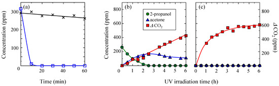
Figure 7.
(a) Temporal concentration changes of gaseous 2-propanol under dark conditions for the TiO2-coated non-porous (crosses) and porous (open squares) glass cloths. (b,c) Concentrations of gaseous 2-propanol, acetone, and CO2 under subsequent UV light irradiation for the TiO2-coated non-porous and porous glass cloths, respectively. The porous sample was prepared by 3 h of leaching. The dark adsorption and photocatalytic deposition experiments were conducted at 15 °C and in the presence of low water content (2 mg/L) in a 2-propanol atmosphere.
Further, the effects of temperature and water content on the adsorption and decomposition abilities of the TiO2-coated porous glass cloth were investigated. Figure 8a depicts the trends of the 2-propanol adsorption under dark conditions in 2-propanol atmospheres with both high (18 mg/L) and low (2 mg/L) water contents. Both the experiments were conducted at 35 °C. A higher amount of 2-propanol was adsorbed from dry air when compared to that adsorbed from moist air. In the presence of high water contents, the alcohol and water molecules compete to be adsorbed on the silanol sites of the silica surface [41], thereby reducing the amount of adsorbed 2-propanol. The concentration changes of 2-propanol, acetone, and CO2 in dry and moist atmospheres during UV irradiation are depicted in Panels (b,c) of Figure 8. Acetone was not detected under either condition, which was similar to that observed in the experiment that was conducted at 15 °C in the presence of a low water content (Figure 7c). Meanwhile, more CO2 was generated at 35 °C than at 15 °C with low water content. In addition, at 35 °C, slightly more CO2 was generated under the high-water atmosphere when compared to that generated under the low-water atmosphere.
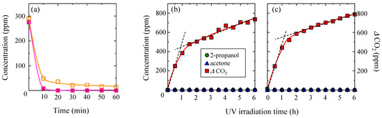
Figure 8.
(a) Temporal concentration changes of 2-propanol during the dark storage of TiO2-coated porous glass cloth in gaseous 2-propanol with 2-mg/L water content (closed squares) and 18-mg/L water content (open squares). (b,c) The concentration changes of 2-propanol, acetone, and CO2 during UV irradiation of the TiO2-coated non-porous glass cloth in gaseous 2-propanol with 2-mg/L and 18-mg/L water contents, respectively. All the experiments were conducted at 35 °C.
The rate of CO2 generation by the decomposition of 2-propanol in the TiO2-coated porous glass cloth (Figure 6c and Figure 7b,c) changed after approximately 1.5 h of UV irradiation. No rate change could be observed in the non-porous sample (Figure 6b), confirming that the rate change phenomenon originated from the porous structure. The proposed decomposition model is depicted in Figure 9. In the TiO2-coated porous glass cloth, the TiO2 particles are mainly supported on the external surface of the porous glass fibers and do not penetrate the pores. Therefore, the photocatalytic reaction occurs on the external fiber surface, whereas the porous interior provides the adsorption sites of 2-propanol, acetone, and water. When the dried sample is inserted into a reactor filled with gaseous 2-propanol, the 2-propanol and water molecules are competitively adsorbed on the SiO2 walls of the pores. Wu et al. clarified that the water and alcohol molecules emit comparatively large adsorption heat when they are adsorbed onto a bare SiO2 surface than that emitted when they are adsorbed onto or when they form cluster with the molecules that have already being adsorbed onto the SiO2 surface [42]. This observation indicates that the weakly and strongly adsorbed molecules coexist on the SiO2 walls of the pores (Figure 9a). Under UV illumination, the 2-propanol molecules near the TiO2 surface are decomposed to CO2 via the acetone intermediate. In the early phase of photocatalytic decomposition, the weakly adsorbed 2-propanol molecules on the SiO2 walls are preferentially desorbed and diffuse from the interior of the fiber to near the TiO2 surface. Further, 2-propanol diffusion provides a sufficient supply of 2-propanol for sustaining CO2 generation at a high rate (Figure 9b). The reaction rate gradually decreases as the supply of weakly adsorbed 2-propanol reduces. In the later phase, the CO2 generation rate is limited by the desorption and diffusion of the strongly adsorbed 2-propanol molecules (Figure 9c). This limiting rate corresponds to the decelerated CO2 generation rate after 1.5 h of light illumination in the photocatalytic decomposition of 2-propanol on the TiO2-coated porous glass cloth (Figure 7c and Figure 8b,c).
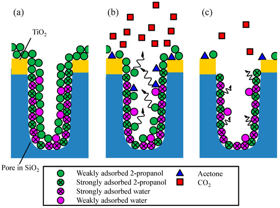
Figure 9.
Schematics of (a) adsorption, (b) early-phase photocatalytic oxidation, and (c) late-phase photocatalytic oxidation on the TiO2-coated porous glass cloth.
Based on this decomposition model, we compared the results of photocatalytic decomposition at 15 °C and 35 °C under a 2-propanol atmosphere with a low (2 mg/L) water content (Figure 7c and Figure 8b). During the early phase of decomposition, the CO2 generation rate was observed to be only slightly higher at 35 °C than that at 15 °C; however, during the later phase of decomposition, the CO2 decomposition rates of the two conditions were observed to be clearly different. More specifically, the CO2 generation rates after 2–6 h of UV light irradiation were 18 and 54 ppm/h at 15 °C and 35 °C, respectively. The higher CO2 generation rate observed at 35 °C can be explained by the accelerated diffusion of 2-propanol from inside the porous glass fibers to the TiO2 surface by a higher temperature.
The effect of water content was further evaluated from the photocatalytic decomposition results at 35 °C in 2-propanol atmospheres with low (2 mg/L) and high (18 mg/L) water contents (Figure 8b,c). After 30 min of light illumination, the CO2 concentrations in the dry and moist atmospheres were observed to be identical; however, the CO2 generation rate changed at CO2 concentrations of 440 and 560 ppm in dry and moist atmospheres, respectively. This result indicates that the CO2 generation rate changed at a later stage of the decomposition process in the moist condition. This difference may be obtained from the condition of 2-propanol adsorption in porous glass fibers. As shown in the decomposition model (Figure 9), the weakly and strongly adsorbed 2-propanol molecules coexisted in the pores. In the moist condition, the abundant water molecules are expected to occupy a large portion of the strong adsorption sites on the bare SiO2 surface, thereby decreasing the ratio of the amount of strongly adsorbed 2-propanol to that of the weakly adsorbed 2-propanol. Because the weakly adsorbed 2-propanol molecules are easily desorbed from the SiO2 walls, a sufficient supply of 2-propanol can continue the generation of CO2 at a constant rate for a certain time. In contrast, in the dry condition, the proportion of strongly adsorbed 2-propanol should be relatively high. Once the weakly adsorbed 2-propanol molecules have been consumed in the early phase, the CO2 generation rate will gradually decrease.
We further discuss the reason why the CO2 generation rates were identical during the earliest phase of 2-propanol decomposition. In the surface-reaction limited situation, the rate of mass transportation is generally greater than the rate of surface reaction; therefore, the decomposition rate is considered to be independent of the reactant concentration. In the mass-transportation limited situation, the rate of surface reaction is greater than the rate of mass transportation, and the decomposition rate is related to the reactant concentration near the reaction site [7]. In our experiments, the concentration of weakly adsorbed 2-propanol in the porous glass fiber was expected to be dependent on the water content; however, the initial CO2 generation rate remained constant. This indicated that the photocatalytic decomposition was limited by the surface reaction on TiO2 in this phase.
Finally, the effect of water on the radical reaction at the photo-illuminated TiO2 surface is discussed. In the photocatalytic reaction on TiO2, the adsorbed water molecules react with the photogenerated carriers at the TiO2 surface and change to hydroxyl radicals [43]. These hydroxyl radicals further diffuse and decompose the organic compounds near the TiO2 surface; therefore, a certain amount of water vapor can enhance the photocatalytic decomposition rate of organic compounds such as 2-propanol [29,44,45]. Further, excess water vapor prevents the adsorption of organic molecules on the TiO2 surface, thereby decreasing the photocatalytic decomposition rate [29,32,44]. However, as noted above, the initial CO2 generation rates estimated from the CO2 concentration after 30 min of UV irradiation were observed to remain the same under both dry and moist conditions. It indicated that the CO2 generation rates under both conditions were very similar because the amount of water in the gaseous phase was not significantly different under both conditions. The majority of the water in the present reactor was expected to be adsorbed on the large Sg of the porous glass fiber cloth. Large water adsorption will decrease the water concentration in the gaseous phase, which can be used to plausibly explain the similar CO2 generation rates at high and low water contents in the earliest phase of 2-propanol decomposition.
In the later phase of the decomposition, the CO2 generation rates were estimated in the UV light irradiation time ranging from 2 to 6 h. The rates were 54 and 46 ppm/h under low and high water content conditions, respectively. Within this range, the water content did not largely influence the CO2 generation rates because the rates were limited by the diffusion of the strongly adsorbed 2-propanol molecules.
3. Materials and Methods
3.1. Materials
The glass fiber cloth was provided by Arisawa Manufacturing Co. Ltd. (Joetsu, Japan). Figure 10 is a photomicrograph of the glass fiber cloth. It has a plain weave structure, and approximately 400 E-glass fibers of 9.1-µm diameters form the warp and weft thread; further, the thread density, the number of warp and the weft thread per certain area of woven fabric was 44 × 32 in 25 × 25 mm2. The thickness of the cloth was 180 µm, and the weight per unit area was 203.5 g/m2. The TiO2 (anatase) nanoparticles were dispersed in 2-propanol (TKD-701, 17.0 wt %, d = 6 nm, TAYCA Co., Osaka, Japan). Further, reagent-grade aqueous hydrochloric acid (HCl; 5 mol/L), ethanol (99.5 wt %), 2-propanol (99.7 wt %), and sodium carbonate (99.5 wt %) were supplied by Wako Pure Chemical Industries Ltd. (Osaka, Japan) and were used without any purification.
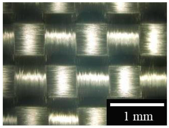
Figure 10.
Photograph of the magnified surface of the E-glass cloth.
3.2. Preparation of the TiO2-Coated Porous Glass Cloth
The organic compounds on the fibers of two pieces of glass cloth (ca. (30 × 35) mm2 × 2, total weight 0.19 g) were eliminated by heating at 500 °C for 1 h. The heat-treated cloth samples were immersed in 13.3 ml of 2.5 mol/L HCl aqueous solution at 40 °C for 0.5, 1, 3, 4, 6, or 12 h in a screw-capped perfluoroalkoxy alkane (PFA) container without stirring. After leaching by HCl, the samples were washed several times in distilled water and were further immersed in 80 ml of distilled water for 10 min. This immersion process was repeated, replacing the water between each immersion, until the pH of the immersing water reached ca. 7 (in this case, after two washes). The samples were washed with ethanol and immersed in sufficient ethanol to perform solvent exchange in the sample pores. After 10 min in ethanol, the samples were dried at 120 °C for 10 min to form the porous glass cloth. A reference sample with a non-porous structure was prepared by heating the glass fiber cloth at 500 °C for 1 h without subsequent acid leaching. This sample was used as the non-porous glass cloth.
TiO2 was coated on both the porous and non-porous glass cloths using the conventional dip-coating method. The TiO2 coating solution was prepared by diluting the TiO2 suspension to 1 wt % in 2-propanol. The glass cloth samples were dipped in the diluted TiO2 suspension and were further pulled up at 1.0 mm/s. The dip-coated samples were subsequently dried at room temperature and at 120 °C for 10 min; further, they were finally heated at 300 °C for 2 h. The obtained samples were referred to as the TiO2-coated porous and non-porous glass cloths. On the other hand, as a reference in XRD measurement, the TiO2 powder sample was also prepared from the TiO2 suspension by drying at 120 °C and subsequently heating at 300 °C for 2 h.
3.3. Characterization
The surface morphologies of the samples were observed by field emission scanning electron microscopy (FE–SEM, Hitachi S-2400 and S-5200, Hitachi High-Technologyies, Tokyo, Japan). Before the FE–SEM observation, the samples were platinum-coated using a sputtering method. The XRD patterns were collected using CuKα radiation (λ = 0.15406 nm, monochromatized by Ni filter) by an X-ray diffractometer (MiniFlex 600, Rigaku Co., Tokyo, Japan) that was operated at 40 kV and 15 mA. The chemical compositions of the samples were analyzed using an X-ray fluorescence (XRF) spectrometer (ZSX Primus μ, Rigaku Co., Tokyo, Japan). For the XRF measurements, glass disks were prepared from the TiO2-coated and uncoated samples as follows. First, 150 mg of the sample was ground with a pestle in an alumina mortar and was formed into a pellet by uniaxial pressing. For acid leaching (by varying the leaching time from 2 to 12 h), the porous samples were mixed with 25 mg of Na2CO3 as the flux. The pressed pellets were sintered by a 3-step heating process (700 °C for 2 h, 800 °C for 2 h, and 900 °C for 4 h), yielding the glass disks that were required to perform XRF analysis. Further, the porous properties of the samples were determined from the N2 gas adsorption isotherms measured at 77 K (BELLSOAP mini II, BEL Japan Inc., Osaka, Japan). Prior to performing the N2 gas adsorption measurements, all the samples were dried in vacuo at 120 °C for 2 h. Their specific surface areas were calculated using the Brunauer–Emmet–Teller (BET) multi-plot method. To analyze their pore-size distributions, the samples were dried in vacuo at 140 °C for 10 h, and the N2 gas adsorption was measured at a very low pressure range (from 10−3 Pa, BELSORP-max-N-VP-CM, BEL Japan Inc., Osaka, Japan). The pore-size distribution was estimated by Saito–Foley fitting using the zeolite Y standard.
The adsorption and photocatalytic decomposition properties of 2-propanol were examined using the TiO2-coated porous glass cloth and the TiO2-coated non-porous glass cloth as reference. The samples were cut into divisions of 0.042 ± 0.001 g for performing the experiments. The cut samples were pre-treated by UV–vis light irradiation under a black light (BL) lamp (FL15BLB, Toshiba Lighting & Technology Co., Yokosuka, Japan, peak wavelength: 365 nm, light intensity at 365 nm: 3.5 mW/cm2 at the sample surface) for 24 h and were subsequently heated at 120 °C in vacuo to eliminate the adsorbed organic molecules and water. Further, the concentrations of 2-propanol and water vapor were adjusted using the apparatus depicted in Figure 11. The air-diluted 2-propanol vapor that was produced by a calibration gas generator (Permeater PD-1B, GASTECH Co., Ayase, Japan) was mixed with the humid air, that was produced through two steps of water bubbling. The resulting mixed gas contained 300 ppm of 2-propanol and 2 or 18 mg/L of water. The 2-propanol concentration in the mixed gas was confirmed by a gas chromatograph (GC-8A, Shimadzu Co., Kyoto, Japan) using a thermal conductivity detector (TCD), a porous polymer beads column (Sunpak-A, 2 m, 160 °C, Shinwa Chemical Industries Ltd., Kyoto, Japan), and He carrier gas (20 mL/min). The water contents in the mixed gas were also confirmed in the gas detector tube (No.6, GASTEC Co., Ayase, Japan). The mixed gas flowed into a gas-tight bag containing two glass vial reactors (diameter: 4 cm; height: 6 cm, volume: approximately 65 mL). After 50 min of gas flow, the pre-treated cloth sample was transferred into one of the vials, and both the vial reactors were immediately sealed with a gas-tight septum. The sealed vials containing the sample, as well as the mixed gas or mixed gas only were transferred to an incubator (maintained at 15 °C or 35 °C) and left for 1 h in the dark. During this time, 2-propanol was adsorbed without conducting a photocatalytic reaction. The glass vials were illuminated by UV–vis light under a BL lamp (with 1.0 mW/cm2 of light intensity at the sample position with no shielding of the glass vial) for 6 h in the incubator. The concentrations of 2-propanol, acetone, and CO2 in the glass vial were determined at 10- and 30-min intervals during the 2-propanol adsorption and photocatalytic decomposition, respectively, by gas chromatography.
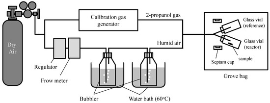
Figure 11.
Apparatus settings for controlling the water content in gaseous 2-propanol.
4. Conclusions
A composite material of TiO2 and porous glass cloth was prepared by acid leaching of an E-glass cloth and subsequent dip-coating of a TiO2 photocatalyst. Working inward from the fiber surface, acid leaching resulted in the formation of a porous shell structure during an early stage. The fibers were observed to become completely porous after 3 h of leaching; however, the specific surface area of the acid-leached E-glass cloth continued to increase for another hour. Consequently, the specific surface area was maximized after 4 h of leaching. The compositional change was observed in the acid-leached E-glass by performing XRF analysis; Al2O3 and B2O3 were eliminated along with the ions of alkaline metals and alkali earth metals, leaving mainly the SiO2 structure. During the photo-catalytic decomposition of 2-propanol, the TiO2-coated porous glass cloth exhibited considerable adsorption ability with respect to 2-propanol and generated CO2 at a higher rate than that of the TiO2-coated non-porous glass cloth. The TiO2-coated porous glass cloth also adsorbed acetone until the decomposition to CO2 was completed. Increasing the temperature from 15 to 35 °C clearly increased the CO2 generation rate of the TiO2-coated porous glass cloth because the diffusion rate of the reactant molecules was accelerated. Further, increasing the moisture content from 2 to 18 mg/L at 35 °C slightly decreased the amount of adsorbed 2-propanol and delayed the change in the rate-controlling step from surface reaction to mass transportation. This indicated that the competitive adsorption of water and 2-propanol in the porous glass fiber decreased the amount of strongly adsorbed 2-propanol in the moist atmosphere. Finally, the porous glass cloth that was prepared from a commercial E-glass cloth provided a sufficiently strong TiO2 support with a high specific surface area. The TiO2-coated porous glass cloth can adsorb and photo-catalytically degrade VOCs such as 2-propanol and acetone. Therefore, it is considered to be a strong candidate for ensuring the practical elimination of gaseous organic pollutants.
Supplementary Materials
The following are available online at http://www.mdpi.com/2073-4344/9/1/82/s1. Figure S1: (a) Surface and (b) fracture cross section of the TiO2 coating on the porous glass cloth, Figure S2: (a) N2 adsorption isotherms of the non-coated and TiO2-coated porous glass cloths and (b) pore-size distributions estimated by Saito–Foley fitting using the adsorption potential for N2 on zeolite Y. Va: adsorbed volume, dp: pore diameter, Vp: pore volume.
Author Contributions
Conceptualization, S.Y.; methodology, S.Y. and A.Y.; investigation, K.H., K.I., and S.Y.; writing–original draft preparation, S.Y.; writing–review and editing A.Y. and K.I.; supervision, A.Y.
Funding
This work was supported in part by Nippon Sheet Glass Foundation for Materials Science and Engineering. A part of the publication cost was supported by the Gender Equality Office, University of Yamanashi.
Conflicts of Interest
The authors declare no conflict of interest.
References
- Kostiainen, R. Volatile organic compounds in the indoor air of normal and sick houses. Atmos. Environ. 1995, 29, 693–702. [Google Scholar] [CrossRef]
- Osha Annotated Table Z-1. Available online: http://www.webcitation.org/71UI8WUO9 (accessed on 7 August 2018).
- Hoffmann, M.R.; Martin, S.T.; Choi, W.; Bahnemann, D.W. Environmental applications of semiconductor photocatalysis. Chem. Rev. 1995, 95, 69–96. [Google Scholar] [CrossRef]
- Pichat, P.; Disdier, J.; Hoang-Van, C.; Mas, D.; Goutailler, G.; Gaysse, C. Purification/deodorization of indoor air and gaseous effluents by TiO2 photocatalysis. Catal. Today 2000, 63, 363–369. [Google Scholar] [CrossRef]
- Wang, S.; Ang, H.M.; Tade, M.O. Volatile organic compounds in indoor environment and photocatalytic oxidation: State of the art. Environ. Int. 2007, 33, 694–705. [Google Scholar] [CrossRef] [PubMed]
- Mamaghani, A.H.; Haghighat, F.; Lee, C.-S. Photocatalytic oxidation technology for indoor environment air purification: The state-of-the-art. Appl. Catal. B Environ. 2017, 203, 247–269. [Google Scholar] [CrossRef]
- Ohko, Y.; Fujishima, A.; Hashimoto, K. Kinetic analysis of the photocatalytic degradation of gas-phase 2-propanol under mass transport-limited conditions with a TiO2 film photocatalyst. J. Phys. Chem. B 1998, 102, 1724–1729. [Google Scholar] [CrossRef]
- Takeuchi, M.; Hidaka, M.; Anpo, M. Efficient removal of toluene and benzene in gas phase by the TiO2/y-zeolite hybrid photocatalyst. J. Hazard. Mater. 2012, 237, 133–139. [Google Scholar] [CrossRef]
- Yoneyama, H.; Torimoto, T. Titanium dioxide/adsorbent hybrid photocatalysts for photodestruction of organic substances of dilute concentrations. Catal. Today 2000, 58, 133–140. [Google Scholar] [CrossRef]
- Ao, C.H.; Lee, S.C. Combination effect of activated carbon with TiO2 for the photodegradation of binary pollutants at typical indoor air level. J. Photochem. Photobiol. A Chem. 2004, 161, 131–140. [Google Scholar] [CrossRef]
- Mo, J.; Zhang, Y.; Xu, Q.; Yang, R. Effect of TiO2/adsorbent hybrid photocatalysts for toluene decomposition in gas phase. J. Hazard. Mater. 2009, 168, 276–281. [Google Scholar] [CrossRef]
- Yasumori, A.; Yanagida, S.; Sawada, J. Preparation of a titania/x-zeolite/porous glass composite photocatalyst using hydrothermal and drop coating processes. Molecules 2015, 20, 2349–2363. [Google Scholar] [CrossRef] [PubMed]
- Zhang, M.; An, T.; Fu, J.; Sheng, G.; Wang, X.; Hu, X.; Ding, X. Photocatalytic degradation of mixed gaseous carbonyl compounds at low level on adsorptive TiO2/SiO2 photocatalyst using a fluidized bed reactor. Chemosphere 2006, 64, 423–431. [Google Scholar] [CrossRef] [PubMed]
- Kang, M.; Hong, W.-J.; Park, M.-S. Synthesis of high concentration titanium-incorporated nanoporous silicates (ti-nps) and their photocatalytic performance for toluene oxidation. Appl. Catal. B Environ. 2004, 53, 195–205. [Google Scholar] [CrossRef]
- Tasbihi, M.; Štangar, U.L.; Škapin, A.S.; Ristić, A.; Kaučič, V.; Tušar, N.N. Titania-containing mesoporous silica powders: Structural properties and photocatalytic activity towards isopropanol degradation. J. Photochem. Photobiol. A Chem. 2010, 216, 167–178. [Google Scholar] [CrossRef]
- Anpo, M.; Aikawa, N.; Kubokawa, Y.; Che, M.; Louis, C.; Giamello, E. Photoluminescence and photocatalytic activity of highly dispersed titanium oxide anchored onto porous vycor glass. J. Phys. Chem. 1985, 89, 5017–5021. [Google Scholar] [CrossRef]
- Yamashita, H.; Ichihashi, Y.; Harada, M.; Stewart, G.; Fox, M.A.; Anpo, M. Photocatalytic degradation of 1-octanol on anchored titanium oxide and on TiO2 powder catalysts. J. Catal. 1996, 158, 97–101. [Google Scholar] [CrossRef]
- Yamashita, H.; Honda, M.; Harada, M.; Ichihashi, Y.; Anpo, M.; Hirao, T.; Itoh, N.; Iwamoto, N. Preparation of titanium oxide photocatalysts anchored on porous silica glass by a metal ion-implantation method and their photocatalytic reactivities for the degradation of 2-propanol diluted in water. J. Phys. Chem. B 1998, 102, 10707–10711. [Google Scholar] [CrossRef]
- Yazawa, T.; Machida, F.; Kubo, N.; Jin, T. Photocatalytic activity of transparent porous glass supported TiO2. Ceram. Int. 2009, 35, 3321–3325. [Google Scholar] [CrossRef]
- Wallenberger, F.T. Commercial and experimental glass fibers. In Fiberglass and Glass Technology: Energy-Friendly Compositions and Applications; Wallenberger, F.T., Bingham, P.A., Eds.; Springer: Boston, MA, USA, 2010; pp. 3–90. ISBN 978-1-4419-0736-3. [Google Scholar]
- Caddock, B.D.; Evans, K.E.; Masters, I.G. Diffusion behaviour of the core-sheath structure in e-glass fibres exposed to aqueous HCl. J. Mater. Sci. 1989, 24, 4100–4105. [Google Scholar] [CrossRef]
- Li, H.; Gu, P.; Watson, J.; Meng, J. Acid corrosion resistance and mechanism of E-glass fibers: Boron factor. J. Mater. Sci. 2013, 48, 3075–3087. [Google Scholar] [CrossRef]
- Kiwi-Minsker, L.; Yuranov, I.; Siebenhaar, B.; Renken, A. Glass fiber catalysts for total oxidation of co and hydrocarbons in waste gases. Catal. Today 1999, 54, 39–46. [Google Scholar] [CrossRef]
- Tanaka, H.; Kuraoka, K.; Yamanaka, H.; Yazawa, T. Development and disappearance of microporous structure in acid treated e-glass fiber. J. Noncryst. Solids 1997, 215, 262–270. [Google Scholar] [CrossRef]
- Kitamura, T.; Ino, J.; Masuda, R.; Fukuchi, H.; Tougeda, H.; Nippon Sheet Glass, Co. Ltd.; Nippon Muki, Co. Ltd. Photocatalyst Supporting Glass Fiber Textile, Manufacturing Method of the Same and Air Filter Apparatus Using the Same. Jpn. Kokai Tokkyo Koho (unexamined patent publication) 2004-002176, 8 January 2004. [Google Scholar]
- Aubry, E.; Ghazzal, M.N.; Demange, V.; Chaoui, N.; Robert, D.; Billard, A. Poisoning prevention of TiO2 photocatalyst coatings sputtered on soda-lime glass by intercalation of sinx diffusion barriers. Surf. Coat. Technol. 2007, 201, 7706–7712. [Google Scholar] [CrossRef]
- Yu, J.; Zhao, X. Effect of substrates on the photocatalytic activity of nanometer TiO2 thin films. Mater. Res. Bull. 2000, 35, 1293–1301. [Google Scholar] [CrossRef]
- Rekoske, J.E.; Barteau, M.A. Kinetics and selectivity of 2-propanol conversion on oxidized anatase TiO2. J. Catal. 1997, 165, 57–72. [Google Scholar] [CrossRef]
- Hager, S.; Bauer, R. Heterogeneous photocatalytic oxidation of organics for air purification by near uv irradiated titanium dioxide. Chemosphere 1999, 38, 1549–1559. [Google Scholar] [CrossRef]
- Chang, C.-P.; Chen, J.-N.; Lu, M.-C. Characteristics of photocatalytic oxidation of gaseous 2-propanol using thin-film TiO2 photocatalyst. J. Chem. Technol. Biotechnol. 2004, 79, 1293–1300. [Google Scholar] [CrossRef]
- Vildozo, D.; Ferronato, C.; Sleiman, M.; Chovelon, J.-M. Photocatalytic treatment of indoor air: Optimization of 2-propanol removal using a response surface methodology (RSM). Appl. Catal. B Environ. 2010, 94, 303–310. [Google Scholar] [CrossRef]
- Kim, S.B.; Hong, S.C. Kinetic study for photocatalytic degradation of volatile organic compounds in air using thin film TiO2 photocatalyst. Appl. Catal. B Environ. 2002, 35, 305–315. [Google Scholar] [CrossRef]
- Coronado, J.M.; Zorn, M.E.; Tejedor-Tejedor, I.; Anderson, M.A. Photocatalytic oxidation of ketones in the gas phase over TiO2 thin films: A kinetic study on the influence of water vapor. Appl. Catal. B Environ. 2003, 43, 329–344. [Google Scholar] [CrossRef]
- Reddy, K.M.; Manorama, S.V.; Reddy, A.R. Bandgap studies on anatase titanium dioxide nanoparticles. Mater. Chem. Phys. 2002, 78, 239–245. [Google Scholar] [CrossRef]
- Kaneko, K. Determination of pore size and pore size distribution. J. Membrane Sci. 1994, 96, 59–89. [Google Scholar] [CrossRef]
- Elmer, T.H.; Nordberg, M.E.; Carrier, G.B.; Korda, E.J. Phase separation in borosilicate glasses as seen by electron microscopy and scanning electron microscopy. J. Am. Ceram. Soc. 1970, 53, 171–175. [Google Scholar] [CrossRef]
- Tanaka, H.; Yazawa, T.; Eguchi, K.; Nagasawa, H.; Matsuda, N.; Einishi, T. Precipitation of colloidal silica and pore size distribution in high silica porous glass. J. Noncryst. Solids 1984, 65, 301–309. [Google Scholar] [CrossRef]
- Saito, A.; Poley, H.C. Argon porosimetry of selected molesular sieves: Experiments and examination of the adapted Horvath-Kawazoe model. Microporous Mater. 1995, 3, 531–542. [Google Scholar] [CrossRef]
- Saito, A.; Poley, H.C. Curvature and parametric sensitivity in models for adsorption in micropores. AIChE J. 1991, 37, 429–436. [Google Scholar] [CrossRef]
- Zhuravlev, L.T. The surface chemistry of amorphous silica. Zhuravlev model. Colloids Surf. A Physicochem. Eng. Asp. 2000, 173, 1–38. [Google Scholar] [CrossRef]
- Chuiko, A.A.; Lobanov, V.V.; Grebenyuk, A.G. Structure of disperse silica surface and electrostatic aspects of adsorption. In Colloidal Silica: Fundamentals and Applications; Bergna, H.E., Roberts, W.O., Eds.; CRC Press: Boca Raton, FL, USA, 2005; pp. 331–360. ISBN 9780824709679. [Google Scholar]
- Wu, D.; Guo, X.; Sun, H.; Navrotsky, A. Energy landscape of water and ethanol on silica surfaces. J. Phys. Chem. C 2015, 119, 15428–15433. [Google Scholar] [CrossRef]
- Murakami, Y.; Kenji, E.; Nosaka, A.Y.; Nosaka, Y. Direct detection of oh radicals diffused to the gas phase from the uv-irradiated photocatalytic TiO2 surfaces by means of laser-induced fluorescence spectroscopy. J. Phys. Chem. B 2006, 110, 16808–16811. [Google Scholar] [CrossRef]
- Luo, Y.; Ollis, D.F. Heterogeneous photocatalytic oxidation of trichloroethylene and toluene mixtures in air: Kinetic promotion and inhibition, time-dependent catalyst activity. J. Catal. 1996, 163, 1–11. [Google Scholar] [CrossRef]
- Bouazza, N.; Lillo-Ródenas, M.; Linares-Solano, A. Photocatalytic activity of TiO2-based materials for the oxidation of propene and benzene at low concentration in presence of humidity. Appl. Catal. B Environ. 2008, 84, 691–698. [Google Scholar] [CrossRef]
© 2019 by the authors. Licensee MDPI, Basel, Switzerland. This article is an open access article distributed under the terms and conditions of the Creative Commons Attribution (CC BY) license (http://creativecommons.org/licenses/by/4.0/).