Review

Insights into the Recent Progress and Advanced Materials for Photocatalytic Nitrogen Fixation for Ammonia (NH3) Production

1
Department of Chemical Engineering, Laval University, Québec, QC G1V 0A6, Canada
2
Centre for Nano and Material Sciences, Jain University, Bangalore 562 112, India
*
Author to whom correspondence should be addressed.
Catalysts 2018, 8(12), 621; https://doi.org/10.3390/catal8120621
Submission received: 20 November 2018 / Revised: 30 November 2018 / Accepted: 30 November 2018 / Published: 4 December 2018
(This article belongs to the Section Photocatalysis)

Abstract

:
Ammonia (NH3) is one of the key agricultural fertilizers and to date, industries are using the conventional Haber-Bosh process for the synthesis of NH3 which requires high temperature and energy. To overcome such challenges and to find a sustainable alternative process, researchers are focusing on the photocatalytic nitrogen fixation process. Recently, the effective utilization of sunlight has been proposed via photocatalytic water splitting for producing green energy resource, hydrogen. Inspired by this phenomenon, the production of ammonia via nitrogen, water and sunlight has been attracted many efforts. Photocatalytic N2 fixation presents a green and sustainable ammonia synthesis pathway. Currently, the strategies for development of efficient photocatalyst for nitrogen fixation is primarily concentrated on creating active sites or loading transition metal to facilitate the charge separation and weaken the N–N triple bond. In this investigation, we review the literature knowledge about the photocatalysis phenomena and the most recent developments on the semiconductor nanocomposites for nitrogen fixation, following by a detailed discussion of each type of mechanism.

1. Introduction

In this current century, the climate changes and energy production are some of the most significant and important challenges that are being faced by the people in the world. In this direction, ammonia (NH3) and the associated chemicals could provide an alternative energy resource. Similar to molecular hydrogen (H2), NH3 is also a carbon-free energy-source for the end-users. Ammonia has a worldwide annual production of around 150 million tons, due to the increasing demand from an increasing world population. However, the depletion of fossil fuels makes the industrial-scale ammonia synthesis processes urges to replace the usages of fossil fuels by a renewable energy source. Currently, NH3 is being manufactured by the traditional Haber-Bosch (HB) process using pure H2 and N2, which requires energy-intensive high temperature (>500 °C) and extremely high pressure (200–300 bar). Nevertheless, the utilization of natural gas as a source of H2 obtained by steam/gas reforming into the production of ammonia takes up about 1–2% world energy every year and belches out hundreds of millions of tons of CO2 annually [1,2].
Specifically, in Canada, there are 11 plants manufacturing NH3 across the country, where they use this HB process to produce ~5 million tons of NH3 every year. Canada provides approximately 12% of the world’s fertilizer-materials and ~25% of the ammonia produced in Canada is being sent to North America for its direct use the agricultural purposes. The fertilizer industry creates ~$12 billion in annual economic activity in Canada. Therefore, it is of a considerable significance to develop the low-energy consumption, sustainable and eco-friendly process to manufacture NH3 through nitrogen fixation in large scale.
This review sheds lights into the recent progress in the development of a variety of routes for the synthesis of advanced materials and emphasizes their application for nitrogen photofixation. This review also concludes with a concise overview of the present status, analyzes potential and future development of photocatalysts with a view towards enhanced performance in different photocatalytic materials.

2. A Brief Insight into the Haber-Bosch Process

The most industrial and practical process for ammonia production is the Haber-Bosch process, where ammonia (NH3) is produced directly from its constituent elements, such as hydrogen (H2) and nitrogen (N2). Conventionally, this synthesis is conducted at 150–250 atm and 400–500 °C, as the gas passes over the reactor with two or four beds of catalyst (Figure 1). Eventually, each time conversion to ammonia is only 15%, by multiple times recycle unreacted gases, an overall conversion of 97% is obtained. The primary source of molecular H2 is methane from the natural gas. In addition, it is estimated that around 3–5% of the world’s natural-gas production is utilized in the Haber-Bosch (HB) process.

2.1. Equilibrium Considerations and Reaction Rate

In the Haber-Bosch process, the formation reaction of NH3 is reversible and the forward reaction of NH3 production is an exothermic: N2(g) + 3H2(g) → 2NH3(g) (H = −92 kJmol−1). According to Le Chatelier’s principle, this reaction will be supported at the lower temperatures. In this process, the temperature must be as low as possible towards getting as much as ammonia as possible in the equilibrium condition. However, under this condition, the reaction does not proceed at an efficient rate. Therefore, two contrasting considerations are occurring in this synthesis. The viable temperature for this process is 400–450 °C, which bound to produce a reasonably high amount of NH3 in the equilibrium mixture (15%) in a very short time.

2.2. Catalyst and Mechanism

The most common catalyst of the Haber-Bosch process based on K2O or Al2O3-promoted iron catalyst. The mechanism that involves the heterogeneous-catalyst is proposed to have the following steps:
N2(g) → N2(adsorbed)
N2(adsorbed) → 2N(adsorbed)
H2(g) → H2(adsorbed)
H2(adsorbed) → 2H(adsorbed)
N(adsorbed) + 3H(adsorbed) → NH3(adsorbed)
NH3(adsorbed) → NH3(g)
Reaction (5) occurs in three steps, forming the NH, NH2 and finally NH3. The experimental evidence to Reaction (2) as being the slow, rate-determining step. This is expected since the nitrogen triple bond is the strongest of the bonds that must be broken.

2.3. Separation of the Ammonia

When the produced NH3 gases depart from the reactor, they are essentially hot and under a very high pressure. However, ammonia will be easily liquefied under such pressure as long as it is not too hot and therefore the temperature of the mixture will be sufficiently lowered for the ammonia gas to turn into a liquid. Notably, the molecular N2 and H2 remain as gaseous states under these high pressures and they can be recycled.

3. Overview: Fundamental of Photocatalytic Nitrogen Fixation

3.1. The Principle of Photocatalysis on Semiconductors

Semiconductors (SCs) are used as photocatalytic materials, thanks to their suitable amalgamation of electronic properties, structure, light-absorption characteristics, charge transport dynamics and favorable lifetime of their excited-state charge carriers. Basically, an SC possesses an energy gap between the top of the filled-valence band (VB) and the bottom of the vacant-conduction band (CB), which is known as the band gap energy of the SC [3,4,5,6]. Thus, the separation of charge carrier between these bands only occurs with sufficient energy supply. In semiconductors, the photocatalytic process involves three main steps: Light absorption, charge separation and catalytic reaction. Under light illumination, the electron absorbs a photon with energy higher than or equal to the band gap energy of the semiconductor, excites from VB to CB and releases hole in the VB (Figure 2). This light-induced promoting electron-hole separation is a prerequisite step in all semiconductor photocatalysis. Finally, the photo-generated species transfer to the semiconductor surface and initiate redox reaction of absorbed reagents. However, electrons and holes are to recombine and dissipate the energy in the bulk (volume) or on the surface of the semiconductor, because of the kinetic-barrier for the electron-hole recombination process is relatively low, resulting in a decrease of reaction efficiency [7]. Therefore, prevention of charge recombination is a significant challenge in the photocatalytic field. In the last decades, there has been a considerable amount of effort to increase the lifetime of photogenerated carriers, such as developing photocatalyst with the nanostructure, co-catalyst, surface engineering and junction [8,9].
Moreover, a wide variety of semiconductors, mainly metal oxide and chalcogenides, have been examined with capability for photocatalyst, but only a few of them are considered to be effective photocatalyst, because of the appreciable band gap. In general, wide-band gap semiconductors prove to be better photocatalytic activity compared with low-band gap catalysts. For example, titanium dioxide showed better photocatalysis than cadmium sulfide for hydrogen production, due to the increased free energy of photo-induced charge species of the TiO2 and the intrinsic low chemical- and photo-chemical stability of the CdS. However, the narrow-band gap materials (such as metal sulfides) absorb solar light better that pave the way to potentially use the effective natural light source, which is the sunlight. Accordingly, a promising strategy with this concern has been attained with the utilization of several methods aiming to improve the electronic state and optical characteristics of semiconductors, including metal deposition, doping, and dye-sensitization. On the other hand, to obtain the effective photocatalytic procedure, the bottom of the CB must be located at a more negative potential than the reduction potential of electron acceptor (A) while the top of CB must beyond the oxidation-potential of electron-donor (D).

3.2. Quantum Yield (QY)

The efficiency of the photocatalytic process is measured by quantum yield (QY), which has been considered to describe the number of molecules converted relative to the total number of incident-photons on the reactor walls for an unknown reactor-geometry and for a polychromatic radiation.
QY ( Φ ) = #   molecule   decomposed #   photon   absorbed
Additionally, quantum yield could be calculated based on the rate of reaction dividing to the absorbed light intensity (Ia),
Φ = Rate Ia .
The measurement of the absorbed light intensity is easy in homogeneous systems; however, it is difficult for heterogeneous reactions, such as thin films or semiconductor suspensions. In this stage, the suspended particle also reflected and scattered incident light instead of total absorption. Thus, it is very exhausted to correct this loss, including 13–76% of the total incident photon flux [10]. Otherwise, light is also absorbed by products or educts of reaction, suggesting QY should be determined at very early reaction time. To conquer such problems in heterogeneous photoreaction, it was proposed replacing the absorbed light intensity by the incident intensity (I0). Therefore, apparent quantum yield (AQY, ς) [11,12] has been termed to measure the efficiency of the photocatalytic process:
ς = Rate I 0 .

3.3. Materials for Photocatalysis

Based on fundamental chemical composition system, all of the semiconducting materials can be divided into three important categories, mainly metal oxides, metal sulfides and metal free semiconductors.
Usually, metal oxides are the most common material, which can be utilized for photocatalysis in various reactions, such as H2 production, CO2 reduction and N2 fixation. This type of materials have a wide range of applications according to their band structure and activities. However, most of them only activate under UV light irradiation due to their large band gap energy. To overcome this difficulty, the substitutions of cations or anions in the lattice of a wide band gap semiconductor has been employed to narrow band gap energy, enhancing the visible light respond. This substitution of cations and anions in the crystal lattice may form intermediate energy levels (due to the energy levels of impurities) within the band gap of photocatalyst that facilitates their absorption in the visible range. For example, titanium dioxide with the properties of stability, non-toxicity and high photocatalytic activity is potentially a suitable catalyst for water splitting reaction. Nevertheless, it only absorbs UV light due to a wide band gap (Eg = 3.2 eV). To deal with this disadvantage, Khan et al. modified n-type TiO2 chemically by doping C on this material. Carbon replaces some of the lattice oxygen atoms, resulting in a decrease in band gap energy to 2.32 eV [13].
Contrary to metal oxides, the metal sulfides normally possess a narrow band gap. Thus, they can absorb visible light to generate electron-hole. Moreover, the conduction reduction potential of water is less negative than their CB and so they can reduce water into molecular hydrogen. Otherwise, these materials also have several disadvantages, such as instability and fast recombination of photoexcited charges. The most common example is cadmium sulfide, one of the best semiconductors with high activity for hydrogen production under visible light illumination. With narrow band gap materials, the recombination process of electron and hole is very easy. Reducing particle size of CdS can provide more active sites, decrease the travel path of migration of photoexcited electron to the semiconductor surface and prevent charge recombination [14]. In addition, combining CdS nanoparticles with other semiconductors can also enhance their stability and photocatalytic activity [15,16,17,18].
Beside these semiconductors, some nitride-based systems also exhibit photocatalytic activities towards water reduction in the visible range of solar light. Recently, graphitic carbon nitride (g-C3N4) has drawn a lot of attention, because of its intrinsic properties, such as narrow band gap and non-toxicity. This metal-free polymeric material shows hydrogen evolution under visible light illumination with high chemical stability. Nevertheless, its photo-conversion efficiency is considerably limited than that of TiO2 or CdS and therefore it requires further efforts to improve its photocatalytic activities.

3.4. Co-Catalyst Loading

A Cocatalyst is an integrated compound to the semiconducting material to promote their photocatalytic activity. In a water decomposition reaction, the cocatalyst can avail enhancing either water reduction or oxidation half reaction. In photocatalysis, cocatalysts are typically tiny metal nanoparticles (NPs), which create a Schottky junction with semiconductor and support for charge-separation in a photocatalyst of a photochemical cell [19,20]. In principle, the interfacial-contact between the semiconductor and metal induces an electric field, which effectively separates the excited electrons and holes more easily [21,22,23]. Additionally, the metal supplies active sites for H2 generation due to its comparatively low over the water reduction potential.
The most common cocatalysts for photocatalysis are Pt, Rh, Au, NiO, and RuO2. Maeda et al. report that loading both Rh/Cr2O3 and Mn2O3 supported on GaN:ZnO can effectively promote overall water splitting under visible light although the quantum yield of this system was relatively low [24]. Maeda proved that Rh/Cr2O3 acted as electron collectors to host hydrogen evolution while the main function of is the active sites for water oxidation reaction. However, almost of cocatalyst are noble metals which are rare and expensive, thus prohibiting their wide scale application. Therefore, the development of non-noble and low-cost cocatalyst is extremely important. The physical and chemical characteristics of the co-catalyst, such as particle size and valence states directly affect their activity and are strongly dependent on their loading method onto the surface of host SCs. Although depositing more co-catalyst (concentration) provides more active sites for photocatalytic reactions, it considerably reduces the absorption ability of the semiconductor photocatalyst. Thus, the concentration or the loading amount of co-catalyst should be controlled and optimized to achieve the maximum activity.

3.5. Localized Surface Plasmon Resonance in Photocatalysis

Localized surface plasmon resonance (LSPR) labels the collective charge carrier oscillations in metal nanoparticle created by an incident field that resonant with the periodic movement of the negative charge against the positive nuclei background [25]. In general, the LSPR appears when the size of the metal nanoparticle is considerably smaller than the wavelength of incident light. Upon resonance irradiation, the charge oscillations induce a large electric dipole at the same frequency as that of the incident electric field. Consequently, the electric field intensity in the vicinity of plasmonic metal nanoparticles strengthens up to 1000 times as high as that of the incident field and greatly increases far-field scattering. In a plasmonic-heterostructure, the stored energy in the LSPR can be (i) transferred to the semiconductor or (ii) re-emitted as scattered photons (Figure 3A).
LSPR effect can be effectively applied in photocatalysis by the non-radiative transfer process. Under visible light excitation, LSPR generates hot electrons in the plasmonic nanostructured metal. It should be noted that these electrons possess higher energies than the level of thermal excitation. The injection of the hot electrons into a semiconductor improves the solar photo-voltaic energy conversion. Additionally, the existence of a Schottky barrier at the junction between the metal/semiconductor systems can block electron migration. If the hot electrons absorb sufficient photon energy, they can overcome the barrier and transfer into the conduction band of semiconductor (Figure 3B). Interestingly, the charge carrier injections can occur either from semiconductor or plasmonic metal. It is likely that the excitation state of the semiconductor and plasmonic metal decide where the charge carriers are injected.
The solar energy conversion efficiency can be improved by plasmonic nanocomposites via the two possible following mechanisms: (1) Direct electron transfer (DET) or by (2) plasmon induced resonant energy transfer (PIRET) [26]. The enhancement of the light absorption in semiconductors by photonic enhancement via (i) increasing the length of the optical path and (ii) concentrating the incident field than that of directly transferring the plasmonic energy from the metal to the semiconductor to induce the charge separation in the semiconductor. The plasmonic charge (hot electron) transfer process is referred to as direct electron transfer, which requires the semiconductor and the plasmonic metal be in direct contact with each other (Figure 3C). However, DET differs in that the plasmonic metal does not have a band gap to determines the charge-transfer kinetics [27]. Rather, the plasmonic carriers have the energy that proportional to the incident photon’s energy besides the Fermi level, therefore they can easily overcome the barriers that are energetically unfavorable at the interface, leading to more choices in the selection of materials. As another mode of non-radiative process, the PIRET is an attractive phenomenon for plasmonic enhancement (Figure 3D).
PIRET describes the non-radiative transfer of energy from the metal LSPR dipole to the semiconductor transition dipole. PIRET depends on the spectral overlap and it does not require any electronic-alignment or even physical-contact to transfer energy as like in DET [29], which essentially provides flexibility in the design of solar energy materials and structures. PIRET can produce electron-hole pairs in the semiconductors, suggesting a strong coupling to the weak band edge states. The plasmon resonance can easily be tuned, which allows for an enhanced solar energy harvesting in the entire visible spectrum. PIRET is also favorable when the charge transfer process creates undesirable effects, such as the degradation of materials or issues in the carrier equilibration.

3.6. Fundamentals of Photocatalytic Nitrogen Fixation Principle

Since the first work reported by Fujishima and Honda, in the early 1970s, the use of photocatalysts, based on semiconductors, has emerged as the most promising and practical solution to address the challenges of energy and environmental issues [30]. In the last few decades, a renewed interest has been devoted in photocatalytic NH3 production, and several papers have illustrated ammonia [31] and nitrate formation [32] using various kinds of semiconducting photocatalysts, plasmon-enhanced systems, and biomimetic systems.
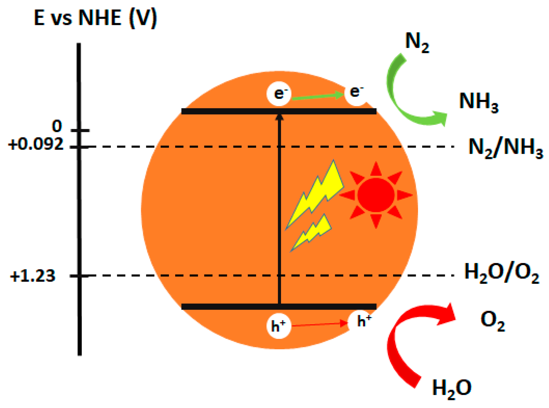
Basically, the photocatalytic process of N2 fixation is divided into several steps as follows: First, under the sunlight irradiation, photo-generated electrons are excited to the CB, leaving holes in the VB. Afterwards, some of the electrons and holes recombine together, meanwhile, other photo-formed holes (h+) oxidize the water into H+, and O2 (Equation (7)) and N2 reduction by hot-electrons lead to the production of NH3 (Equation (8)). As a result, NH3 is synthesized from water and N2 under ambient conditions using the sunlight as an energy source (Equation (9)). Figure 4 demonstrates the scheme process of photocatalyst materials using for the reduction of nitrogen to ammonia.
2H2O + 4h+ → O2 + 4H+
N2 + 6H+ + 6e → 2NH3
½N2 + 3/2H2O → NH3 + ¾O2
Although the proposed photocatalytic fixing nitrogen pathway is acceptable, many pending questions regarding the mechanisms, rates, and thermodynamics still remain. The protonation reactions versus standard potential are summarized by Lyndley et al. (Table 1). Thermodynamically, ammonia formation is favored, with an energy difference of 0.43 V between NH3 and N2H4 and a 1.26 V between NH3 and N2H2. In a thermodynamic aspect, the half-reaction generated NH3 is capable of any photocatalyst semiconductor possessing a bandgap energy larger than 1.2 eV with proper conduction and valence band position. However, this half reaction involves multiple-electron transfer (6 electrons) and thus may be more kinetically challenging. Another limitation is the absorption of N2 molecules over semiconductor photocatalysts and cleavage of highly stable N-N triple bond in order to activate dinitrogen. To overcome these challenges, it is necessary to create appropriate active sites that can effectively absorb nitrogen. This active site also serves as a trapping cage to capture electrons then transfer to absorbed nitrogen as well as suppress charge carrier recombination.

4. Classification of Photocatalysts for N2 Fixation Based on Active Sites

4.1. Metal Active Sites

4.1.1. Iron Active Sites

It should be noted that the catalyst of iron is the common catalyst in the Haber-Bosch process due to its good interaction with dinitrogen and weakening N–N bond [33]. In fact, recent studies indicate that ferric photocatalyst is capable of nitrogen reduction to ammonia. However, it is well-known that pure iron oxide had no activity in N2 photofixation. To overcome this bottleneck, several researchers have employed a various method in the synthesis of defect iron catalyst. Tennakone [34] and his co-worker reported the first system of N2 reduction using amorphous Fe2O3·nH2O under visible light irradiation. Fe2O3 was prepared by gradual addition of KOH to FeCl3 solution and purged with N2. After irradiated visible light for 40 min, a maximum ammonia concentration of ca. 4 µmol·L−1 was obtained and continuously decreased due to the decomposition of NH3 to nitrate in the solution, which poisoned the catalyst. Therefore, NH3 must be removed immediately from the reaction site to maintain catalytic efficiency. Khader et al. successfully prepared a mixture of α-Fe2O3 and Fe3O4, which was effective in photo-reduction of nitrogen for about 580 h [35]. Interestingly, in the existence of 5 at% iron in the form of Fe2+ in the partially reduced Fe2O3, NH3 was detected in an aqueous slurry of the catalyst under UV illumination.
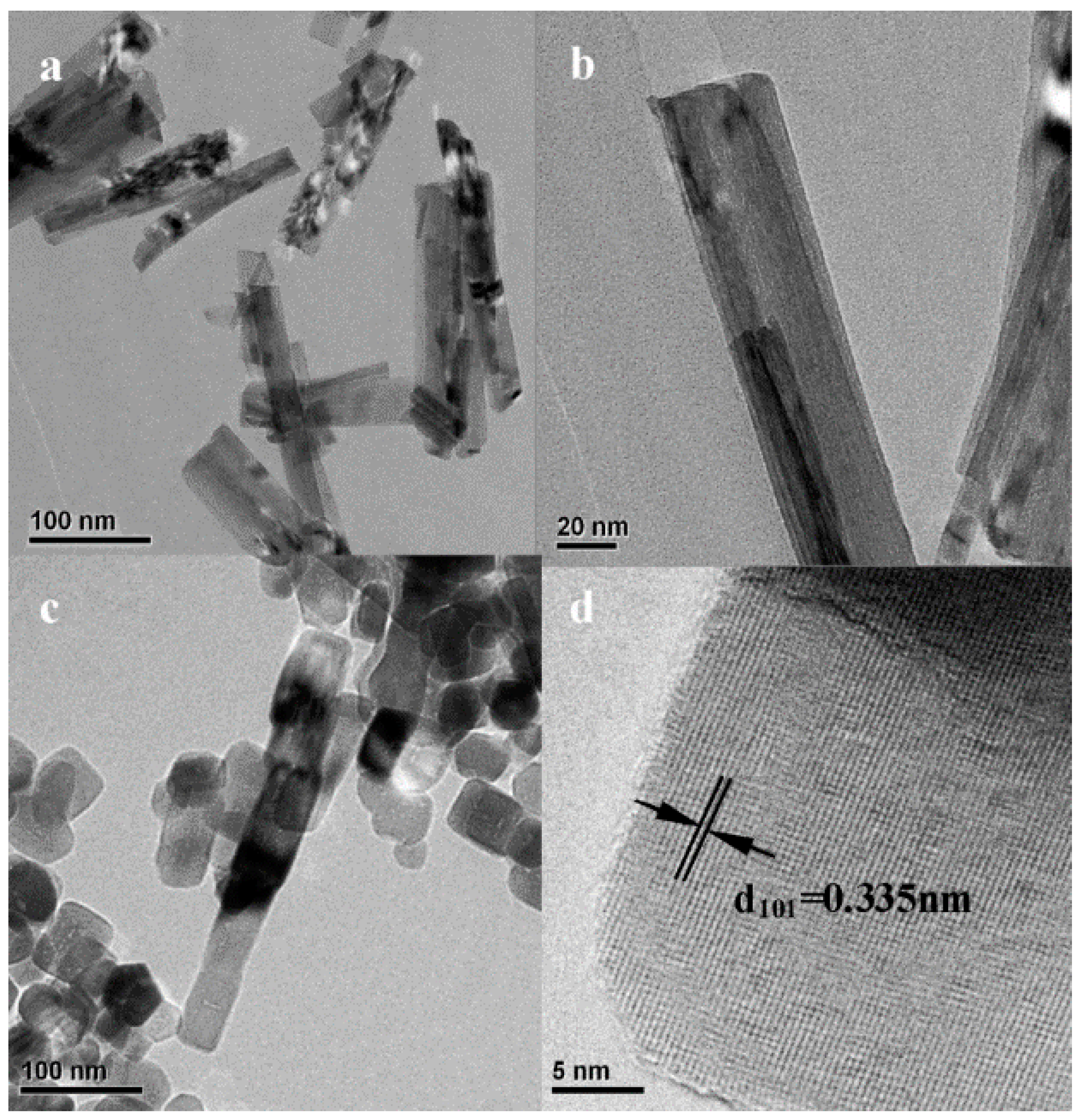
On the other hands, doping Fe into metal oxide, such as TiO2, Al2O3, ZnO, is a practical strategy for utilization of iron active site catalysts. Most of the studies have been focused on metallic Fe modified titanium dioxide photocatalyst. In addition, there has been considerable debate over the role of cation Fe on iron titania photocatalyst. The earlier work suggested that the introduction of Fe3+ as an impurity in titania can play an indirect role in decreasing bandgap energy of semiconductor as well as hinders the recombination of photo-generated electron-hole pairs, consequently enhance the absorption ability and the photoactivity. Zhao et al. investigated the photocatalytic activity of Fe-doped TiO2 with highly exposed (101) facets [36]. The quantum yield of nitrogen photo-reduction using ethanol as scavenger can be reached to 18.27 × 10⁻² m−2. The transmission electron microscopy (TEM) images confirmed that Fe3+ ions are successfully incorporated into the anatase crystal and substituted for Ti4+ in the TiO2 lattice (Figure 5). Zhao and Soria [37] reported that even doping Fe3+ can improve catalytic activity higher than pristine TiO2, but an excess amount of Fe3+ doping can limit the continuous growth of TiO2 particles and poisoning the catalyst. In a continuous work of previous studies, further investigations of mechanism on iron titanate photocatalyst were conducted by Rusina [38] and Krich [39] The electron transfer system of photo(electro)catalytic N2 reduction on the Fe2Ti2O7 thin film includes a series of processes of nitrogen-diazene-hydrazine-ammonia-nitrate. Moreover, Lashgari proposed a N2 photofixation mechanism based on H-atom production [40]. In addition to Fe doped metal oxide materials, non-metal oxide semiconductors were modified with iron. Hu et al. adapted graphitic carbon nitride doping with Fe3+ for conversion of nitrogen to ammonia [41]. It was found that the N≡N bond is prolonged when N2 molecules interact with Fe3+ sites. The delocalization of electron in σg2p orbital (HOMO) of nitrogen when N2 adsorbed on Fe3+ doping sites leads to its orbital energy almost overlaps to that of πg*2p orbital (LUMO), indicating the direct role of iron in activating the N2 molecule. The highest NH4+ production rate of 5.4 mgL−1h−1g−1 was achieved with 0.05 wt% Fe doping, which is 13.5 folds compared to pristine g-C3N4. For the comparison of photocatalytic activities of ammonia production based on iron active site photocatalyst, the selected literature report is summarized in Table 2.

4.1.2. Titanium Active Sites

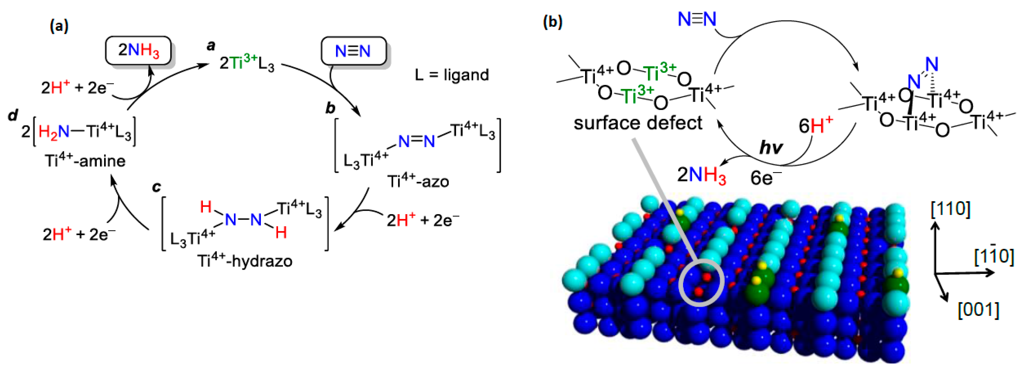
Among all the well-known photocatalysts, TiO2 is the most prominent material and has applied in a variety of photocatalytic applications, because of its abundance, efficient charge separation, and stability. In earlier publications, the metal doped titanium dioxide or titanate was used for photocatalytic fixing nitrogen. In later studies, trivalent titanium complex has been employed to promote the N≡N cleavage [47,48]. Figure 6a illustrates a typical role of Ti3+ reacted with N2 via electron donation. These reduction reactions create Ti4+-amine complexes which finally release NH3 with regenerated trivalent Ti3+ complexed. Inspired by this suggestion, Hirakawa et al. have successfully synthesized reduced titania with Ti3+ defects, which served as the adsorption sites for N2 and trapping sites for the photogenerated electron [49]. The proposed mechanism is shown in Figure 6b. The solar-to-conversion efficiency is 0.02%. However, it is still lower than that of natural- and artificial-photosynthesis, therefore, an improvement of that material in photocatalytic activity is necessary.

4.1.3. Molybdenum Active Sites

Owing to excellent electrical, optical, and photovoltaic properties, ultrathin transition metal dichalcogenides (TMDs) have been considered as promising materials. Among them, MoS2 semiconductor is known as an efficient photocatalyst for hydrogen evolution and CO2 conversion reaction. Recently, its application in N2 reduction has been unveiled since the first report of Sun’s group [50]. In this research, the photocatalytic activity of MoS2 photocatalysts under different preparation conditions was investigated. The results show that the sonicated ultrathin MoS2 induced charged excitons (trions) when applying visible light (Figure 7a). These trions carried multiple electrons in one bound state, which located around Mo sites. Naturally, three Mo atoms surround adsorbed dinitrogen on the S vacancy and facilitate the six-electron transfer process. Consequently, the rate of ammonia production of 325 µmol.g-1h-1 was achieved, which is much higher than the rate of hydrothermal MoS2 and bulk MoS2 samples. Particularly, it can be concluded that a multiple electrons reduction process was responsible for the enhancement of photocatalytic dinitrogen reduction to ammonia.
In addition, enzyme nitrogenase has also been widely studied for application of catalytic nitrogen fixation [53]. A nitrogenase is a two-component system comprising a MoFe protein and an associated Fe protein. Based on this inspiration, in 2015, Banergee and Kanatzidis supposed that solid chalcogels consisiting of FeMoS inorganic clusters is able to reduce dinitrogen to amonia by utilizing white light [51]. The double-cubane Fe2Mo6S8 units were associated by Sn2S6 ligands (Figure 7b) to form a stable amorphous complex in aqueous solution. The FeMoS cluster (FeMoS cofactor, a synthetic clusters bearing Mo−Fe linkages) of the biomimetic chalcogel system is a structural and functional analogue of the MoFe active site in the enzyme nitrogenase. This work showed that the high density of FeMoS active sites can boost multi-electron transformation as well as mimic the function of biological nitrigenases in N2 fixation. In order to gain insights into the performance of the FeMo cofactor in nitrogenases. Brown and coworkers fabricated a biohybrid system of nitrogenase coupled with CdS semiconductor. The MoFe protein coated CdS nano rods produced 315 nmol of NH3 per min over one mg MoFe-protetin, which is estimated for 3.3% of Quantum Yield. In MoFe Protein, FeMo cofactor plays a role as an active site, receiving photogenetated electrons from CdS nanocrystals. By changing condition reactions, Liu found that lack of FeMo cofactor did not produce amonia. Furthermore, the role of Mo and Fe in the MoFe protein are revealed in another study. Liu et al. discussed the photocatalytic activity of nitrogen reduction by the nitrogenase-inspired biometic chalcogel [52]. In this system, Mo2Fe6S8(SPh)3, Fe4S4 and redox-inert ions are assembled with Sn2S6 (Figure 7c). However, iron was expected to be more active than molybdenum for the solar reduction of N2, due to the fact that a weak bonding orbital between nitrogen and iron emerged via the localized orbital analysis. Moreover, their conclusion that the Fe is a better active site for N2 binding than Mo has been demonstrated by recent biochemical and spectroscopic data.

4.1.4. Nickel Active Sites

The study of Schrauzer and Guth examined the effect of various metal dopant over titania for photocatalytic NH3 formation. In addition to doping Mo and Fe, only Co and Ni dopant performed the contribution to the enhancement of NH3 production efficiency [42]. The other metal doped, such as Pd, V, Cu, showed no improvement in catalytic activity. It can be explained by the influence of Ni, Co accelerates the phase transformation while this phenomenon is unobtainable for other dopants. This explaination is consistent with the conclution of Ranjit. In his work, Ranjit also compared 12 elements doped TiO2 photocatalyst and found the order of photoactivity was Fe > Co > Mo > Ni. Ye et al. loaded Ni2P on a binary metal sulfide solid solution for photocatalytic N2 fixation under visible light [54]. The deposited transition metal phosphide affects both the VB and CB of metal sulfide, resulting in higher photocatalytic reduction ability. Moreover, the transition metal phosphide of Ni2P supports the photo-induced charge carrier separation process, which is confirmed by photoluminescence spectra (PL) and electrochemical impedance spectroscopy (EIS)For Ni2P/Cd0.5Zn0.5S, the NH3 production rate achieved 101.5 μmol L−1 h−1 (35.7 times than that of unloaded metal phosphine cocatalyst), corresponding to 4.23% of apparent quantum efficiency at 420 nm.

4.2. Non-Metal Vacancies

4.2.1. Oxygen Vacancies

In the earlier studies, the synthesis of ammonia by N2 photoreduction has been far from acceptable, because of the impoverished binding of N2 to catalytic active sites and the high energy of the intermediates required in the reactions. It has been concerned a significant challenge of activation and cleavage of the highly stable N≡N triple bond relying only on light-induced electrons from semiconductor materials in solar-driven N2 fixation. To conquer this challenge, the electron-transfer supportive centers should be introduced as the primary-step active sites to absorb the molecular N2 and weaken the N≡N bond, which could allow the photo-induced electrons to inject for the subsequent reduction reactions. Oxygen vacancies (OVs), with their rich localized-electrons, have been proved to serve as electron trapping centers that can effectively capture and activate the inert gases, such as O2, CO2, and N2 in particular. Table 3 summarizes the most recent advanced oxide materials containing Ovs for nitrogen photo-fixation.

Oxygen Vacancies Based on Titanium Dioxide

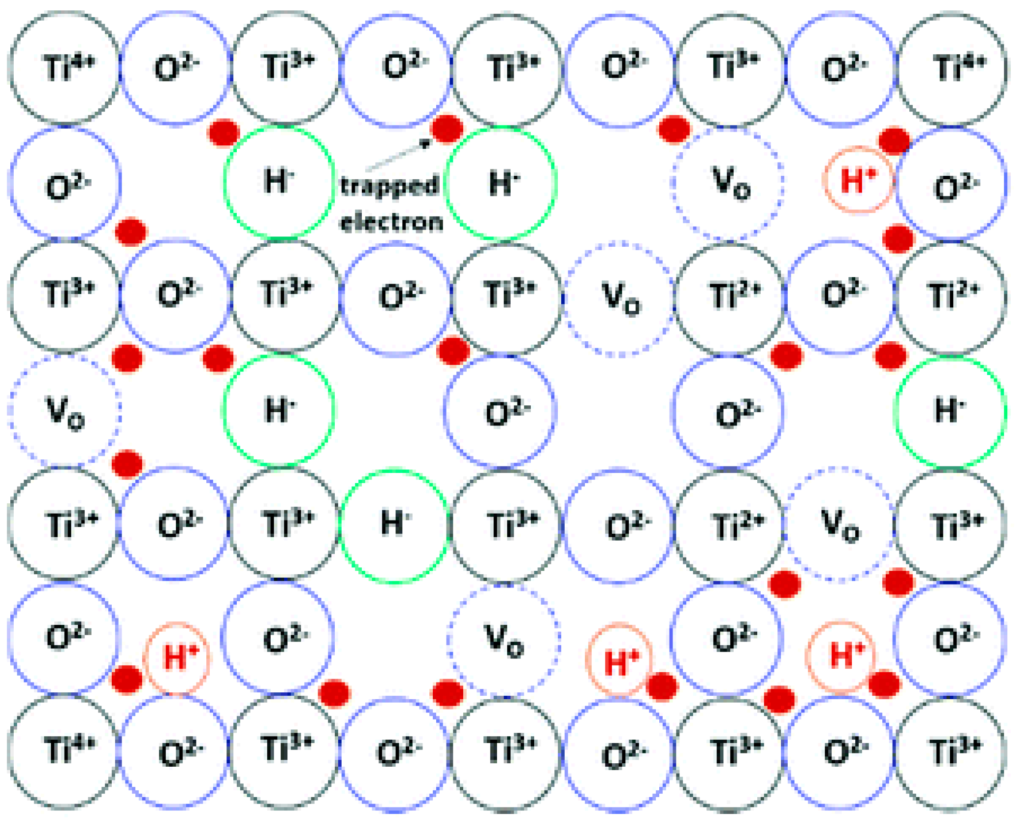
Recently, Zhang et al. created solid-state sources of solvated electron based on reduced titanium dioxide for nitrogen photofixation [55] (Figure 8). Since oxygen vacancies were introduced in TiO2, electrons are trapped at the vacancy sites and released by infrared (IR)-light excitation, consequently reducing N2 to NH3. The number of trapped electrons can be enriched by tuning the concentration of oxygen defects. However, the amount of generated ammonia nearly ceased after 24 h, due to the consumption of releasable trapped electron. For recharging of electrons, the reacted TiO2 could be treated with chemical reduction method.
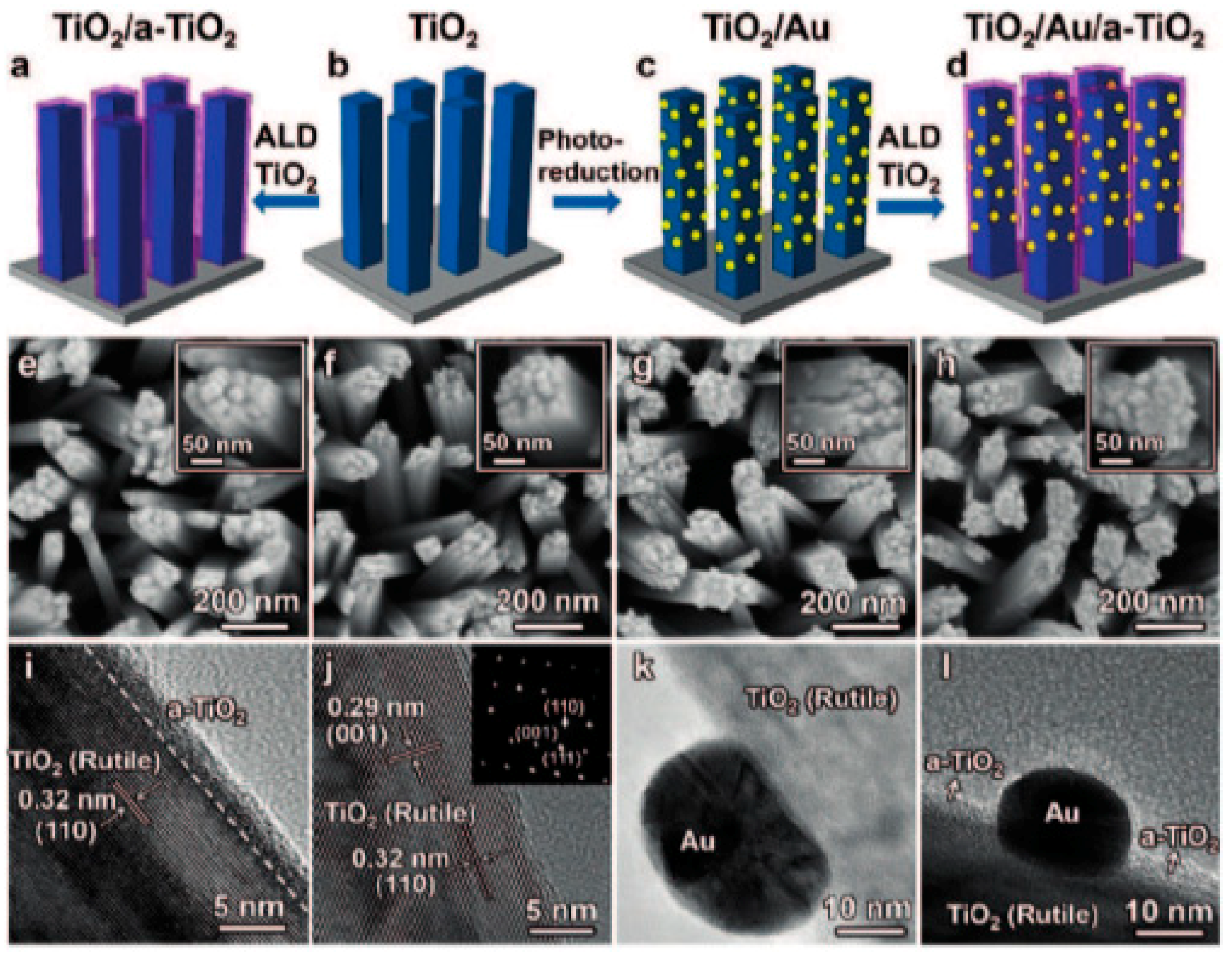
Another group, Li, and his partner conducted the photo-electrochemical reduction of N2 to NH3 on the surface oxygen vacancies of plasmon-induced TiO2 [56] (Figure 9). Li suggested that only superficial oxygen vacancies can act as active sites, the other internal vacancies in crystal structure play a role as undesired defects. By using the atomic layer deposition method, oxygen vacancies are successfully introduced onto the surface of TiO2 without creating bulk defects (introduction of oxygen vacancies to bulk structure to form defects). It is worthy to note that surface oxygen vacancies not only serve as N2 absorption sites, but also promote charge-carrier transportation to the adsorbed nitrogen while bulk-vacancies act as recombination centers to trap the photo-excited electrons and holes. The optimized ammonia production rate of 13.4 nmol cm−2h−1 was obtained by the sample of surface oxygen vacancies modified TiO2/Au/amorphous TiO2 electrode, which is 2.6-folds higher than pristine TiO2. Moreover, Hirai and his group have studied systematically the role of oxygen vacancy and Ti3+ active site [49]. He concluded that oxygen vacancy can facilitate the dissociation of the N≡N triple bond. This conclusion is consistent with Zhang and Li’s group.
In contrast with the above research, Medford and Comer employed density functional theory (DFT) analysis to discuss the role of oxygen vacancy [63]. The defected surface (110) titania possessing an oxygen vacancy was compared to pristine TiO2 by examining nitrogen reduction. The DFT calculations rejected the traditional mechanism of nitrogen photofixation that the breaking of N-N bond is conducted directly by oxygen vacancy. Otherwise, his hypothesis is that a considerable stabilization of the unstable NHx intermediates by the oxygen vacancy makes NHx binding close to exo-thermic, indicating that it can enhance nitrogen reduction and ammonia generation after the N–N bond has been dissociated.

Oxygen Vacancies Based on Bismuth Oxyhalide

Bismuth oxyhalides, BiOX (X = Cl, Br, and I), have recently gained considerable interests for their intrinsic optical properties; they are also practical for industrial applications, such as the photodecomposition of organic pollutants and CO2 reduction. The structural layer of BiOX provides sufficient space for the polarization of atoms and the as-formed internal electric field will play an effective role in their efficient charge separation and transfer process.
Due to containing interior oxygen vacancy, bismuth oxyhalides has been considered as a promising catalyst for nitrogen fixation, particularly in photofixation [64,65]. Most recently, Bi5O7Br nanotubes were investigated its photoactivity of ammonia evolution by Wang et al. [55]. Owing to the excessive number of oxygen vacancies as active centers, the highest NH3 production rate is obtained at 1.38 mmol·g−1h−1, corresponding to an apparent quantum yield of 2.3% at 420 nm. However, bismuth oxybromide photocatalysts are susceptible to photocorrosion. During the reduction reaction, the oxygen vacancies is filled by O atoms form the water, reducing the number of active sites and lose its activity. Interestingly, the reacted oxygen vacancies can be regenerated by applying visible light illumination, which continuously provides the reversible light-switchable surface oxygen vacancies for N2 fixation. Figure 10A demonstrates repeated circulation of oxygen vacancies over TiO2 for ammonia photo-production.
In 2015, Zhang and Li studied the effect of oxygen vacancies on the exposed (001) facets BiOBr nanosheets to fix nitrogen under ambient condition [31]. The theoretical analysis calculated the extension of the N–N triple bond increased by 0.055 Å as absorbed N2 molecules are activated by oxygen vacancies (Figure 10B). Also, the oxygen vacancies as the initial electron acceptor can avoid the electron-hole recombination and considerably promote the interfacial charge transfer. In this paper, the UV-Visible light driven N2 fixation rate was measured to be 223.3 µmolg−1h−1 without using sacrificial agent and a noble-metal cocatalyst. As a succession of the previous study, Zhang’s group clarified that two distinct structure of surface oxygen vacancy on different facets of BiOCl nanosheets completely determine the N2 fixation mechanisms [59]. For instance, the N2 reduction reaction on the oxygen vacancies of BiOCl (010) facets followed a symmetric alternating pathway which generates N2H2-level and N2H4-level species. Whereas, an asymmetric distal mechanism selectively produces ammonia (001) facets without involving the generation of N2H2 or N2H4. By DFT calculation, the accepted adsorption possibility of N2 on BiOCl surfaces was investigated. On the (001) facets, absorbed N2 combines with two nearest Bi atoms in the sublayer to form a terminal end-on bridging, consequently, the activation exhibited the increasing N–N bond length to 1.137 Å (Figure 10(Ca)). Separately, different absorbed N2 performs a larger extent of N2 activation and elongates bond length to 1.198 Å (Figure 10(Cb)) through a side on bridging mode (dinitrogen interacts with two nearest Bi atoms in the outer layer and the one next nearest Bi atom in the sub-layer on the (010) facet). Respectively, the quantum yields under UV irradiation were 1.8% h−1 and 4.3% h−1 on the (001) and (010) surface of BiOCl. Inspired by Zhang’s group, Bai et al. examined the photocatalytic activity of different Bi5O7I facets over solar-driven N2 fixation reaction [60]. At 356 nm UV-light irradiation, the apparent quantum efficiency of (001) surface Bi5O7I was 5.1%, which is 2.2 times higher than that of (100) planes (Figure 10D). After exposure to (001) facets, the charge carrier separation and mobility were dramatically boosted, elucidating the enhancement of photoactivity on (001) Bi5O7I facets.
Although most publications highlight noteworthy attention on the exposure of different facets, it is more possible that the combined effects facet-dependent studies and oxygen vacancies-dependent studies will open a new and interesting perspective and provide inspiration for the development of advanced photocatalysts for N2 photoreduction. In addition, the combination of experimental data and theoretical simulations is highly necessary to fully interpret the N–N triple bond activation and pathway the NH3 formation mechanism. Thus, further study on the facet controlled and vacancy-mediated bismuth oxyhalides should be dedicated in the future to emphasize the scientific aspects and reveal the appropriate reaction steps for the N2 photofixation.

4.2.2. Nitrogen Vacancies

The introduction of defects in photocatalyst materials is completely considered as an effective method to enhance the photocatalytic nitrogen fixation. Instead of oxygen vacancy, another alternative strategy for using non-metal vacancy to fix nitrogen has been to utilize nitrogen vacancies in order to absorb and weaken N2 molecules. Because nitrogen vacancies have the same size and shape as the nitrogen atoms in di-nitrogen, nitrogen vacancies (NVs) are favorable in the selective chemisorption and activation of N2 [66]. This interprets why the N2 fixation rate remained unchanged when N2 was replaced by air as the N2 source. In addition, nitrogen vacancies significantly improved the separation of charge carriers by trapping photo-excited electrons and facilitating the interfacial charge transfer to the adsorbed N2.
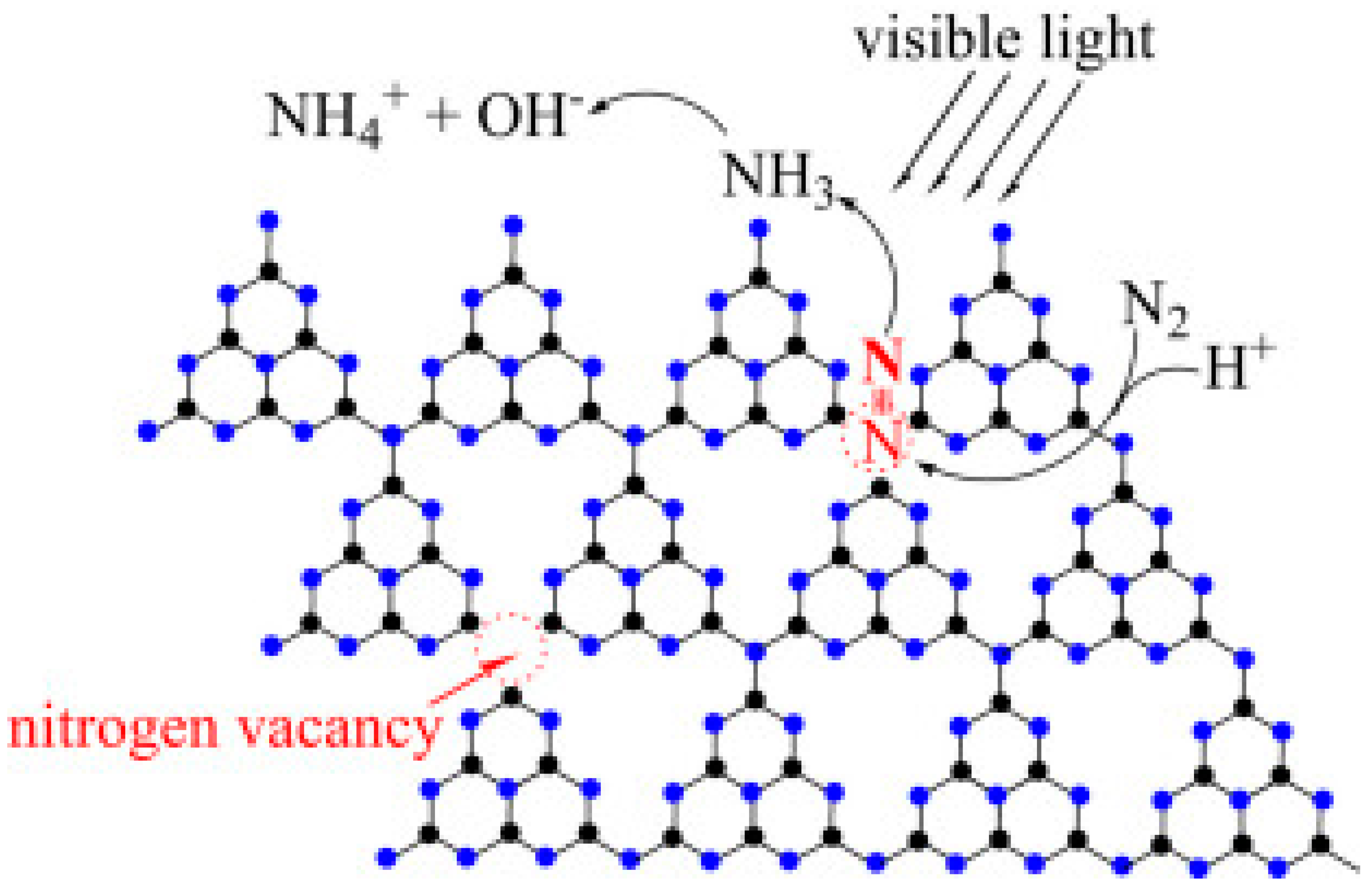
From the time when the first report on graphitic carbon nitride (g-C3N4) in 2009, this metal-free polymeric photocatalyst has received tremendous interest, due to its specific properties such as excellent stability, cost-effectiveness, and environmental benignity. Recently, graphitic carbon nitride composing of nitrogen vacancies has been employed as a photocatalyst for reduction of nitrogen to ammonia. In 2015, the first introduction of nitrogen vacancies induced g-C3N4 for visible light driven NH3 production was reported by Dong [66]. After 15 h of light illumination, nitrogen vacancies incorporated g-C3N4 generated 1.24 mmolh−1g−1 of photofixation rate while bare g-C3N4 show no catalytic activity, suggesting the indispensable role of nitrogen vacancies in promoting photoactivity. However, lacking nitrogen in defects modified carbon nitride structure slightly enlarged bandgap energy than that of pristine samples, resulting in a reduction of visible light absorption ability. In contrast to Dong’s research, Li suggests that even the influence of nitrogen vacancies on the band structure decrease the bandgap energy, it is not the main factor that affects the photocatalytic nitrogen reduction. Li et al. have fabricated nitrogen vacancies assisted g-C3N4 by infrared ray assisted microwave (IM-CN(x), where x denots the time) [67]. Under microwave treatment, abundant nitrogen vacancies were formed and served as chemical absorption centers. By DFT calculation, it was found that chemisorbed N–N triple bond is elongated from 1.107 Å to 1.242 Å due to the formation of σ bond between N2 molecule and the nearest C atom. Consequently, the NH4+ evolution rate obtained by IM-CN(30) sample was 5.1 mg L−1 h−1 gcat−1, which is 5-fold and 2.5-fold higher than those of bulk CN520 and microwave treated CN(20). Similarly, Ma and Li have prepared high specific surface area carbon nitride by a dissolve-regrowth method, which is capable of N2 photoreduction [68]. Based on experimental results and theoretical simulation, Ma demonstrated the possible nitrogen photofixation over large surface area g-C3N4 containing N-vacancies (Figure 11). First, absorbed N2 molecule in N-vacancy is activated by four-electron which occupies the anti-bonding orbitals of N atoms, then H+ reacts with the activated N2 molecule to produce NH3 and finally form NH4+.
Besides using nitrogen vacancy active sites, nitrogen defects is also applied for producing NH3 under solar simulation. Li et al. introduced cyano-deficient onto bulk g-C3N4 by cleavage C=N bond via KOH etching treatment [69]. The as-prepared g-C3N4 (ACN) possesses a porous structure with ladder-like thin layers. Li concluded that the presence of cyano groups not only reduce conduction band of bulk g-C3N4, but also act as an electron acceptor, capturing electrons and inhibiting electron-hole recombination. Moreover, the existent of cyano defects conduct more adsorption site for the N2 activation. Therefore, the formation of cyano groups by etching bulk g-C3N4 with KOH is the main reason for the enhanced photocatalytic N2 fixation activity. After 4 h testing catalytic activity, the NH4+ concentration of ACN-10% increase to 51.65 mg/L, which is 7.6 times higher than bulk samples. Figure 12 shows the formation of cyano deficient g-C3N4 and N2 photofixation mechanism.

4.2.3. Sulfur Vacancies

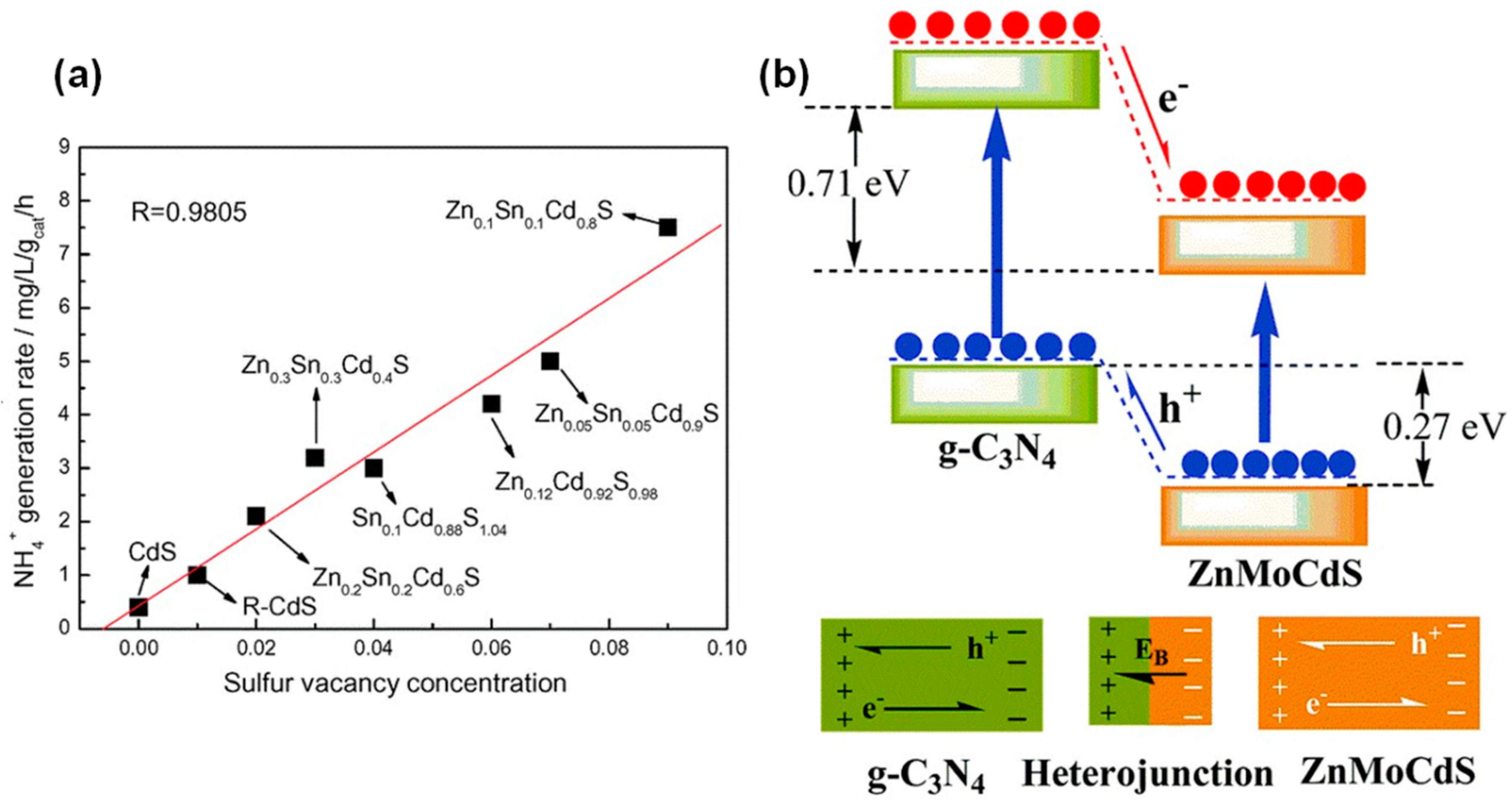
Due to similar chemical properties with oxygen, Hu hypothesized that sulfur vacancies have N2 absorption ability as oxygen vacancies [70]. In his study, a tri-component metal sulfide of Zn0.1Sn0.1Cd0.8S was prepared by the hydrothermal process. Under visible light irradiation, the photocatalyst performs an outstanding activity in nitrogen fixation, because of containing a high concentration of sulfur vacancies. This research implied that the photocatalytic nitrogen fixation activity is linearly depended on the sulfur vacancy concentration. The NH4+ production rates over the various vacancy concentrations were compared and illustrated in Figure 13a, confirming that the concentration of sulfur vacancies plays a significantly pivotal role in the N2 photofixation ability.
Hu also discussed the role of Zn, Sn metal doping in the creation of sulfur vacancies rather than act as active sites to promote catalytic ability. The proof of elongated N–N triple bond from 1.164 Å to 1.213 Å over sulfur vacancies proves that sulfur vacancies can aid the activation of N2 instead of doped metal. In this regard, Hu’s group continues to investigate the effect of different metal doping on ternary metal sulfide. Mo and Ni doped CdS can distort the crystal structure, leading to the formation of sulfur vacancies in obtained tri-component metal sulfide [72]. In order to compare the influence of sulfur vacancies, the as-prepared samples were calcined in O2 gas to remove sulfur vacancies. In results, the photocatalytic NH4+ generation rates of Mo0.1Ni0.1Cd0.8S photocatalyst is 3.2 mg L−1 h−1 gcat−1, which is 10-folds higher in comparison with the oxidized sulfur vacancies sample of Mo0.1Ni0.1Cd0.8SO. Hu concluded that the sulfur vacancies not only act as chemical absorption sites, but also capture photo-generated electrons, suppress charge recombination and encourage interfacial charge transfer.
A strategy of coupling carbon nitride with sulfur vacancies doped metal sulfide was applied for the reduction of N2 under visible light. At the same time, two similar heterojunction system of g-C3N4/ZnSnCdS and g-C3N4/ZnMoCdS were assembled by Cao et al. [71,73]. In general, the photo-induced electrons will be excited and migrated from g-C3N4 to the quaternary metal sulfide whereas the photo-generated holes are transferred in the reversed direction and consumed by hole scavenger. Additionally, the sulfur vacancies could trap immigrated electrons form g-C3N4 and intrinsic electrons in metal sulfide then transport immediately to activated N2. The schematic of electron-hole separation and transportation is depicted in Figure 13b. As the photoinduced electrons and holes are spatially separated, the charge recombination will be drastically inhibited, which is of highly beneficial for enhancing the photocatalytic activity. Under visible light irradiation, the highest NH4+ evolution rates of g-C3N4/ZnSnCdS and g-C3N4/ZnMoCdS are 7.5 and 3.5 mg L−1 h−1 gcat−1, respectively, which is 33.3 and 13.5 times higher compared to those of individual g-C3N4.

4.3. Metal Cocatalyst and Plasmon Enhancement

4.3.1. Metal Cocatalyst

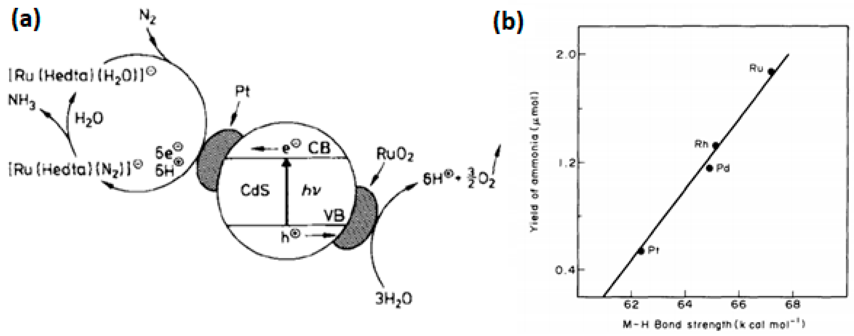
In addition to the introduction of interior active sites, transition metals can be employed as exterior active sites by loaded on the semiconductor photocatalysts, namely cocatalyst. Cocatalysts play a critical role in photocatalysis. As electron acceptor, cocatalysts promote electron-hole separation and impede photogenerated charge carrier recombination. Among a variety of cocatalyst, platinum and ruthenium have been considered as the most effective cocatalyst, particularly in hydrogen evolution and CO2 conversion. Inspired by prior research, Miyama engaged Pt loading TiO2 and CdS for the improvement of N2 photoreduction [74]. For both TiO2 and CdS, the yield of ammonia was increased approximately 1.5 times after introducing noble metal cocatalyst. Several years later, Mirza group applied both Pt and RuO2 as a reduction and oxidation cocatalyst in CdS [75]. The Pt particles in this system act as electron trapping centers which capture photoexcited electrons and perform reduction reaction. Whereas, the RuO2 serves as a hole scavenger to consume generated hole, balancing electric charge. Figure 14a demonstrates the mechanism of photocatalytic ammonia evolution based on CdS/Pt/RuO2 photocatalyst.
In 1996, Ranjit et al. systematically investigated the impact on photocatalytic NH3 evolution by the nature and amount of four noble metals decorated TiO2 [76]. It is worth noting that ammonia was not produced by using pure TiO2 photocatalyst. However, the metallization of titania results in the increasing of ammonia generation rate. It was found that the production rate is depended on several factors. First, the noble metals form the ohmic contact with semiconductor and serve as electron sinks where can easily accommodate the flow of electron transfer, suppressing electron-hole recombination. Secondly, the report supposed that the key role of the installed metal is to stabilize Hads formed on the metal, thus enhancing the ammonia yield. Figure 14b illustrates the linear dependent between the Metal-Hads bond strength and the yield of ammonia. This proposal is consistent with another work investigating Ru, Fe, and Os cocatalysts [77], where it was found that metal cocatalysts for NH3 production needed to have a high over-potential for H2 evolution; where the metals with high over-potentials for the hydrogen evolution reaction (Ru and Fe) having higher NH3 activity than the metals with low hydrogen evolution reaction over-potential. Based on experimental data, Ranjit deduced that the catalytic activity of the nanocomposite photocatalyst is observed in the trend Ru > Rh > Pd > Pt. It is clearly seen that the trend is reversed in the hydrogen evolution reaction. Medford suggested that the role of the metal site is to minimize hydrogen evolution rather than being a cocatalyst for NH3 synthesis [78].

4.3.2. Plasmon Enhancement

A fundamentally different approach for loading transition metal supported fixing nitrogen has been demonstrated to enhance light absorption through the surface plasmonic enhancement [79,80,81,82,83]. In order to increase the NH3 production rate by harnessing the localized surface plasmon resonance, most recent studies have focused on using gold nanoparticles as a plasmonic structure. Owing to high light-harvesting properties, gold in a nanoparticle can absorb visible light and induce surface plasmon effect, which can inject hot electrons into the semiconductor conduction band. Oshikiri and his partner assembled a photoelectrode, with Au nanoparticles and Ru cocatalyst co-loaded Nb-SrTiO3 [80]. The hypothesized mechanism was proposed that the excited hot electron is transferred to SrTiO3 semiconductor and continuously injected into Ru cocatalyst. At the Ru surface, nitrogen and proton are reduced to ammonia. In contrast, the generated holes localize near the Au/Nb-SrTiO3/water interface and immediately oxidize hydroxyl ions and ethanol (Figure 15a). The ammonia production was observed at long wavelengths up to 800 nm, implying plasmon-induced charge separation promoted nitrogen reduction in the cathode and oxidation in the anodic side. However, Ru cocatalyst not only accelerates N2 reduction, but also for H2 evolution because of stable absorption of H2 onto a Ru surface. Later, a replacement of Ru cocatalyst with Zr/ZrOx cocatalyst was reported by the initial group in 2016 [81]. In the Au/Nb-SrTiO3/Zr/ZrOx system, the NH3 generation rate is prominently higher than that of Ru system, due to Zr prefers binding N* adatoms rather than H* adatoms. DFT calculation proved that the Zr is effective at limiting the hydrogen evolution reaction. An energy diagram of this system is provided in Figure 15b.
Furthermore, Zheng, Terazono, and Tanuma attempted to synthesize ammonia at room temperature using Os-Au nanocomposite catalyst which was prepared by directly sputtered Os onto Au layer [79]. The generation of ammonia was observed under visible light irradiation between 550 and 650 nm, corresponding to the conversion rate of 0.003% at 550 nm. Originally, neither pure Au nor Os nanoparticle showed photoactivity in ammonia synthesis. Although pure Au nanoparticles exhibit LSPR effect of photon energy absorption to generate electron, but are unable to encourage the N2 reduction reaction. Whereas, Os nanoparticle is active for N2 fixation, but inactive in the visible light region. Therefore, the assembly of Au–Os nanocomposite motivates the photon energy resonance transfer from Au nanoparticles to Os layer (Figure 16a), enhancing NH3 yield. By contrast, for the first time, Ali and his colleagues hypothesized that gold nanoparticles can serve as reduction cocatalyst [82]. In his work, solar-driven nanostructured plasmon enhanced black silicon photoelectrode produces ammonia yield of 320 mg m−2 in a day. The variety of controlled experiment confirm the roles of individual layers, which is described in Figure 16b. Gold nanoparticles (GNP) loaded black silicon (bSi) provide reduction active sites, receiving transferred electron form photon absorber bSi. While Cr layer acts as sacrificial hole sink where scavenge photogenerated holes by the oxidation of sulfite ions. In results, the NH3 production of the GNP/bSi/Cr cell increases to around two-folds that of the GNP/bSi and eight-folds that of pure bSi.

5. Conclusions

Utilization of solar light for energy production and environmental protection is one of the most critical challenges in the near future for researchers and scientists. Photocatalyst based on semiconductors is an effective route to employ the plentiful energy from the sun. Unfortunately, industrial application of this strategy is still limited by ineffective light absorption and fast electrons-holes recombination process of photocatalyst semiconductor. Thus, the development of the active photocatalyst system is required. A variety of methods have been introduced to improve the photocatalytic efficiency, such as combining multicomponent semiconductor together, metal or non-metal doping, usage of cocatalyst, and plasmon-enhancement. The main purposes of these methods are to enhance the visible light absorption ability, to narrow band gap energy of semiconductor, to increase the charge separation, to decrease charge-recombination and to supply more active sites on the surface of the nanocomposite semiconductor.
Over the last decade, nitrogen photofixation has been attracted many interests for the synthesis of ammonia by nitrogen and water under solar irradiation. There are two main strategies for developing efficient photocatalyst of nitrogen reduction. Introduction of metal active sites or non-metal vacancies not only provide more active centers to absorb nitrogen, but also weaken and activate N-N triple bond. Whereas, noble metals, such as Pt, Ru, Pd, Rh loaded photocatalysts can act as electron acceptors, promoting charge carrier separation and suppressing electron hole recombination. In addition, loading gold nanoparticle induces LSPS effect, which can enhance visible light absorption effectively. In this review report, we have demonstrated the advantages and disadvantage of each group of active centers-based semiconductors. Understanding the strong points and drawbacks of these materials is a very important step to develop new effective photocatalyst for NH3 evolution based on solar-driven nitrogen fixation.

Funding

This research was funded by MITACS, FQRNT and NSERC.

Acknowledgments

Authors gratefully acknowledge the funding support from the MITACS, FQRNT and NSERC.

Conflicts of Interest

Authors have no conflicts of interest to declare.

References

  1. Service, R.F. New recipe produces ammonia from air, water, and sunlight. Science 2014, 345, 610. [Google Scholar] [CrossRef] [PubMed]
  2. Licht, S.; Cui, B.; Wang, B.; Li, F.-F.; Lau, J.; Liu, S. Ammonia synthesis by N2 and steam electrolysis in molten hydroxide suspensions of nanoscale Fe2O3. Science 2014, 345, 637–640. [Google Scholar] [CrossRef] [PubMed]
  3. Linsebigler, A.L.; Lu, G.; Yates, J.T. Photocatalysis on TiO2 Surfaces: Principles, Mechanisms, and Selected Results. Chem. Rev. 1995, 95, 735–758. [Google Scholar] [CrossRef]
  4. Datta, R.S.; Ou, J.Z.; Mohiuddin, M.; Carey, B.J.; Zhang, B.Y.; Khan, H.; Syed, N.; Zavabeti, A.; Haque, F.; Daeneke, T.; et al. Two dimensional PbMoO4: A photocatalytic material derived from a naturally non-layered crystal. Nano Energy 2018, 49, 237–246. [Google Scholar]
  5. Daeneke, T.; Khoshmanesh, K.; Mahmood, N.; de Castro, I.A.; Esrafilzadeh, D.; Barrow, S.J.; Dickey, M.D.; Kalantar-zadeh, K. Liquid metals: Fundamentals and applications in chemistry. Chem. Soc. Rev. 2018, 47, 4073–4111. [Google Scholar]
  6. Kisch, H. Semiconductor Photocatalysis-Mechanistic and Synthetic Aspects. Angew. Chem. Int. Ed. 2013, 52, 812–847. [Google Scholar] [CrossRef] [PubMed]
  7. Furube, A.; Asahi, T.; Masuhara, H.; Yamashita, H.; Anpo, M. Charge Carrier Dynamics of Standard TiO2 Catalysts Revealed by Femtosecond Diffuse Reflectance Spectroscopy. J. Phys. Chem. B 1999, 103, 3120–3127. [Google Scholar] [CrossRef]
  8. Habisreutinger Severin, N.; Schmidt-Mende, L.; Stolarczyk Jacek, K. Photocatalytic Reduction of CO2 on TiO2 and Other Semiconductors. Angew. Chem. Int. Ed. 2013, 52, 7372–7408. [Google Scholar] [CrossRef]
  9. Li, X.; Yu, J.; Low, J.; Fang, Y.; Xiao, J.; Chen, X. Engineering heterogeneous semiconductors for solar water splitting. J. Mater. Chem. A 2015, 3, 2485–2534. [Google Scholar] [CrossRef]
  10. Schiavello, M.; Augugliaro, V.; Palmisano, L. An experimental method for the determination of the photon flow reflected and absorbed by aqueous dispersions containing polycrystalline solids in heterogeneous photocatalysis. J. Catal. 1991, 127, 332–341. [Google Scholar] [CrossRef]
  11. Kisch, H.; Bahnemann, D. Best Practice in Photocatalysis: Comparing Rates or Apparent Quantum Yields? J. Phys. Chem. Lett. 2015, 6, 1907–1910. [Google Scholar] [CrossRef] [PubMed]
  12. Buriak, J.M.; Kamat, P.V.; Schanze, K.S. Best Practices for Reporting on Heterogeneous Photocatalysis. ACS Appl. Mater. Interfaces 2014, 6, 11815–11816. [Google Scholar] [CrossRef] [PubMed]
  13. Khan, S.U.M.; Al-Shahry, M.; Ingler, W.B. Efficient Photochemical Water Splitting by a Chemically Modified n-TiO2. Science 2002, 297, 2243–2245. [Google Scholar] [CrossRef]
  14. Jing, D.; Guo, L. A Novel Method for the Preparation of a Highly Stable and Active CdS Photocatalyst with a Special Surface Nanostructure. J. Phys. Chem. B 2006, 110, 11139–11145. [Google Scholar] [CrossRef] [PubMed]
  15. Cao, J.; Sun, J.Z.; Hong, J.; Li, H.Y.; Chen, H.Z.; Wang, M. Carbon Nanotube/CdS Core–Shell Nanowires Prepared by a Simple Room-Temperature Chemical Reduction Method. Adv. Mater. 2004, 16, 84–87. [Google Scholar] [CrossRef]
  16. Wang, X.; Liu, G.; Lu, G.Q.; Cheng, H.-M. Stable photocatalytic hydrogen evolution from water over ZnO–CdS core–shell nanorods. Int. J. Hydrog. Energy 2010, 35, 8199–8205. [Google Scholar] [CrossRef]
  17. Wang, X.; Liu, G.; Chen, Z.-G.; Li, F.; Wang, L.; Lu, G.Q.; Cheng, H.-M. Enhanced photocatalytic hydrogen evolution by prolonging the lifetime of carriers in ZnO/CdS heterostructures. Chem. Commun. 2009, 23, 3452–3454. [Google Scholar] [CrossRef]
  18. Hou, J.; Wang, Z.; Kan, W.; Jiao, S.; Zhu, H.; Kumar, R.V. Efficient visible-light-driven photocatalytic hydrogen production using CdS@TaON core-shell composites coupled with graphene oxide nanosheets. J. Mater. Chem. 2012, 22, 7291–7299. [Google Scholar] [CrossRef]
  19. Khan, S.U.M.; Majumder, S.A. Optimization of p-silicon surface by etching and electrodeposition of Pt and Ni for photosplitting of water. Int. J. Hydrog. Energy 1989, 14, 653–660. [Google Scholar] [CrossRef]
  20. Akikusa, J.; Khan, S.U.M. Photoelectrolysis of water to hydrogen in p-SiC/Pt and p-SiC/ n-TiO2 cells. Int. J. Hydrog. Energy 2002, 27, 863–870. [Google Scholar] [CrossRef]
  21. Gurunathan, K. Photocatalytic hydrogen production using transition metal ions-doped γ-Bi2O3 semiconductor particles. Int. J. Hydrog. Energy 2004, 29, 933–940. [Google Scholar] [CrossRef]
  22. Jang, J.S.; Yoon, K.Y.; Xiao, X.; Fan, F.-R.F.; Bard, A.J. Development of a Potential Fe2O3-Based Photocatalyst Thin Film for Water Oxidation by Scanning Electrochemical Microscopy: Effects of Ag−Fe2O3 Nanocomposite and Sn Doping. Chem. Mater. 2009, 21, 4803–4810. [Google Scholar] [CrossRef]
  23. Jang, J.S.; Choi, S.H.; Kim, H.G.; Lee, J.S. Location and State of Pt in Platinized CdS/TiO2 Photocatalysts for Hydrogen Production from Water under Visible Light. J. Phys. Chem. C 2008, 112, 17200–17205. [Google Scholar] [CrossRef]
  24. Maeda, K.; Xiong, A.; Yoshinaga, T.; Ikeda, T.; Sakamoto, N.; Hisatomi, T.; Takashima, M.; Lu, D.; Kanehara, M.; Setoyama, T.; et al. Photocatalytic Overall Water Splitting Promoted by Two Different Cocatalysts for Hydrogen and Oxygen Evolution under Visible Light. Angew. Chem. Int. Ed. 2010, 49, 4096–4099. [Google Scholar] [CrossRef] [PubMed]
  25. Clavero, C. Plasmon-induced hot-electron generation at nanoparticle/metal-oxide interfaces for photovoltaic and photocatalytic devices. Nat. Photonics 2014, 8, 95. [Google Scholar] [CrossRef]
  26. Ma, X.-C.; Dai, Y.; Yu, L.; Huang, B.-B. Energy transfer in plasmonic photocatalytic composites. Light Sci. Appl. 2016, 5, e16017. [Google Scholar] [CrossRef]
  27. Mubeen, S.; Hernandez-Sosa, G.; Moses, D.; Lee, J.; Moskovits, M. Plasmonic Photosensitization of a Wide Band Gap Semiconductor: Converting Plasmons to Charge Carriers. Nano Lett. 2011, 11, 5548–5552. [Google Scholar] [CrossRef]
  28. Fan, W.; Leung, M. Recent Development of Plasmonic Resonance-Based Photocatalysis and Photovoltaics for Solar Utilization. Molecules 2016, 21, 180. [Google Scholar] [CrossRef]
  29. Cushing, S.K.; Li, J.; Meng, F.; Senty, T.R.; Suri, S.; Zhi, M.; Li, M.; Bristow, A.D.; Wu, N. Photocatalytic Activity Enhanced by Plasmonic Resonant Energy Transfer from Metal to Semiconductor. J. Am. Chem. Soc. 2012, 134, 15033–15041. [Google Scholar] [CrossRef]
  30. Fujishima, A.; Honda, K. Electrochemical Photolysis of Water at a Semiconductor Electrode. Nature 1972, 238, 37. [Google Scholar] [CrossRef]
  31. Li, H.; Shang, J.; Ai, Z.; Zhang, L. Efficient Visible Light Nitrogen Fixation with BiOBr Nanosheets of Oxygen Vacancies on the Exposed {001} Facets. J. Am. Chem. Soc. 2015, 137, 6393–6399. [Google Scholar] [CrossRef] [PubMed]
  32. Yuan, S.-J.; Chen, J.-J.; Lin, Z.-Q.; Li, W.-W.; Sheng, G.-P.; Yu, H.-Q. Nitrate formation from atmospheric nitrogen and oxygen photocatalysed by nano-sized titanium dioxide. Nat. Commun. 2013, 4, 2249. [Google Scholar] [CrossRef] [PubMed] [Green Version]
  33. Bozso, F.; Ertl, G.; Grunze, M.; Weiss, M. Interaction of nitrogen with iron surfaces: I. Fe(100) and Fe(111). J. Catal. 1977, 49, 18–41. [Google Scholar] [CrossRef]
  34. Tennakone, K.; Wickramanayake, S.; Fernando, C.A.N.; Ileperuma, O.A.; Punchihewa, S. Photocatalytic nitrogen reduction using visible light. J. Chem. Soc. Chem. Commun. 1987, 14, 1078–1080. [Google Scholar] [CrossRef]
  35. Khader, M.M.; Lichtin, N.N.; Vurens, G.H.; Salmeron, M.; Somorjai, G.A. Photoassisted catalytic dissociation of water and reduction of nitrogen to ammonia on partially reduced ferric oxide. Langmuir 1987, 3, 303–304. [Google Scholar] [CrossRef]
  36. Zhao, W.; Zhang, J.; Zhu, X.; Zhang, M.; Tang, J.; Tan, M.; Wang, Y. Enhanced nitrogen photofixation on Fe-doped TiO2 with highly exposed (101) facets in the presence of ethanol as scavenger. Appl. Catal. B Environ. 2014, 144, 468–477. [Google Scholar] [CrossRef]
  37. Soria, J.; Conesa, J.C.; Augugliaro, V.; Palmisano, L.; Schiavello, M.; Sclafani, A. Dinitrogen photoreduction to ammonia over titanium dioxide powders doped with ferric ions. J. Phys. Chem. 1991, 95, 274–282. [Google Scholar] [CrossRef]
  38. Rusina, O.; Linnik, O.; Eremenko, A.; Kisch, H. Nitrogen Photofixation on Nanostructured Iron Titanate Films. Chem. A Eur. J. 2003, 9, 561–565. [Google Scholar] [CrossRef] [PubMed]
  39. Linnik, O.; Kisch, H. On the mechanism of nitrogen photofixation at nanostructured iron titanate films. Photochem. Photobiol. Sci. 2006, 5, 938–942. [Google Scholar] [CrossRef]
  40. Lashgari, M.; Zeinalkhani, P. Photocatalytic N2 conversion to ammonia using efficient nanostructured solar-energy-materials in aqueous media: A novel hydrogenation strategy and basic understanding of the phenomenon. Appl. Catal. A General 2017, 529, 91–97. [Google Scholar] [CrossRef]
  41. Hu, S.; Chen, X.; Li, Q.; Li, F.; Fan, Z.; Wang, H.; Wang, Y.; Zheng, B.; Wu, G. Fe3+ doping promoted N2 photofixation ability of honeycombed graphitic carbon nitride: The experimental and density functional theory simulation analysis. Appl. Catal. B Environ. 2017, 201, 58–69. [Google Scholar] [CrossRef]
  42. Schrauzer, G.N.; Guth, T.D. Photocatalytic reactions. 1. Photolysis of water and photoreduction of nitrogen on titanium dioxide. J. Am. Chem. Soc. 1977, 99, 7189–7193. [Google Scholar] [CrossRef]
  43. Tennakone, K.; Bandara, J.M.S.; Thaminimulla, C.T.K.; Jayatilake, W.D.W.; Ketipearachchi, U.S.; Ileperuma, O.A.; Priyadarshana, M.K.A. Photoreduction of dinitrogen to ammonia by ultrafine particles of iron hydroxide oxide (Fe(O)OH) formed by photohydrolysis of iron(II) bicarbonate. Langmuir 1991, 7, 2166–2168. [Google Scholar] [CrossRef]
  44. Lu, Y.; Yang, Y.; Zhang, T.; Ge, Z.; Chang, H.; Xiao, P.; Xie, Y.; Hua, L.; Li, Q.; Li, H.; et al. Photoprompted Hot Electrons from Bulk Cross-Linked Graphene Materials and Their Efficient Catalysis for Atmospheric Ammonia Synthesis. ACS Nano 2016, 10, 10507–10515. [Google Scholar] [CrossRef] [PubMed]
  45. Tennakone, K.; Fernando, C.A.N.; Wickramanayake, S.; Damayanthi, M.W.P.; Silva, L.H.K.; Wijeratne, W.; Illeperuma, O.A.; Punchihewa, S. Photocatalytic reduction of nitrogen to ammonia with coprecipitated Fe(III) and Ti(IV) hydrous oxides. Sol. Energy Mater. 1988, 17, 47–53. [Google Scholar] [CrossRef]
  46. Ileperuma, O.A.; Kiridena, W.C.B.; Dissanayake, W.D.D. Photoreduction of nitrogen and water on montmorillonite clays loaded with hydrous ferric oxide. J. Photochem. Photobiol. A Chem. 1991, 59, 191–197. [Google Scholar] [CrossRef]
  47. Baumann, R.; Stumpf, R.; Davis, W.M.; Liang, L.-C.; Schrock, R.R. Titanium and Zirconium Complexes That Contain the Tridentate Diamido Ligands [(i-PrN-o-C6H4)2O]2-([i-PrNON]2-) and [(C6H11N-o-C6H4)2O]2-([CyNON]2-). J. Am. Chem. Soc. 1999, 121, 7822–7836. [Google Scholar] [CrossRef]
  48. Van Tamelen, E.E.; Fechter, R.B.; Schneller, S.W. Conversion of molecular nitrogen to hydrazine. J. Am. Chem. Soc. 1969, 91, 7196. [Google Scholar] [CrossRef]
  49. Hirakawa, H.; Hashimoto, M.; Shiraishi, Y.; Hirai, T. Photocatalytic Conversion of Nitrogen to Ammonia with Water on Surface Oxygen Vacancies of Titanium Dioxide. J. Am. Chem. Soc. 2017, 139, 10929–10936. [Google Scholar] [CrossRef]
  50. Sun, S.; Li, X.; Wang, W.; Zhang, L.; Sun, X. Photocatalytic robust solar energy reduction of dinitrogen to ammonia on ultrathin MoS2. Appl. Catal. B Environ. 2017, 200, 323–329. [Google Scholar] [CrossRef]
  51. Banerjee, A.; Yuhas, B.D.; Margulies, E.A.; Zhang, Y.; Shim, Y.; Wasielewski, M.R.; Kanatzidis, M.G. Photochemical Nitrogen Conversion to Ammonia in Ambient Conditions with FeMoS-Chalcogels. J. Am. Chem. Soc. 2015, 137, 2030–2034. [Google Scholar] [CrossRef] [PubMed]
  52. Liu, J.; Kelley, M.S.; Wu, W.; Banerjee, A.; Douvalis, A.P.; Wu, J.; Zhang, Y.; Schatz, G.C.; Kanatzidis, M.G. Nitrogenase-mimic iron-containing chalcogels for photochemical reduction of dinitrogen to ammonia. Proc. Natl. Acad. Sci. USA 2016, 113, 5530–5535. [Google Scholar] [CrossRef] [PubMed]
  53. Hoffman, B.M.; Lukoyanov, D.; Yang, Z.-Y.; Dean, D.R.; Seefeldt, L.C. Mechanism of Nitrogen Fixation by Nitrogenase: The Next Stage. Chem. Rev. 2014, 114, 4041–4062. [Google Scholar] [CrossRef] [PubMed]
  54. Ye, L.; Han, C.; Ma, Z.; Leng, Y.; Li, J.; Ji, X.; Bi, D.; Xie, H.; Huang, Z. Ni2P loading on Cd0.5Zn0.5S solid solution for exceptional photocatalytic nitrogen fixation under visible light. Chem. Eng. J. 2017, 307, 311–318. [Google Scholar] [CrossRef]
  55. Wang, S.; Hai, X.; Ding, X.; Chang, K.; Xiang, Y.; Meng, X.; Yang, Z.; Chen, H.; Ye, J. Light-Switchable Oxygen Vacancies in Ultrafine Bi5O7Br Nanotubes for Boosting Solar-Driven Nitrogen Fixation in Pure Water. Adv. Mater. 2017, 29, 1701774. [Google Scholar] [CrossRef]
  56. Li, C.; Wang, T.; Zhao, Z.J.; Yang, W.; Li, J.F.; Li, A.; Yang, Z.; Ozin Geoffrey, A.; Gong, J. Promoted Fixation of Molecular Nitrogen with Surface Oxygen Vacancies on Plasmon-Enhanced TiO2 Photoelectrodes. Angew. Chem. Int. Ed. 2018, 57, 5278–5282. [Google Scholar] [CrossRef] [PubMed]
  57. Sun, S.; An, Q.; Wang, W.; Zhang, L.; Liu, J.; Goddard Iii, W.A. Efficient photocatalytic reduction of dinitrogen to ammonia on bismuth monoxide quantum dots. J. Mater. Chem. A 2017, 5, 201–209. [Google Scholar] [CrossRef] [Green Version]
  58. Zhang, X.; Zhang, G.; Zou, J. Nitrogen reduction utilizing solvated electrons produced by thermal excitation of trapped electrons in reduced titanium oxide. New J. Chem. 2018, 42, 6084–6090. [Google Scholar] [CrossRef]
  59. Li, H.; Shang, J.; Shi, J.; Zhao, K.; Zhang, L. Facet-dependent solar ammonia synthesis of BiOCl nanosheets via a proton-assisted electron transfer pathway. Nanoscale 2016, 8, 1986–1993. [Google Scholar] [CrossRef]
  60. Bai, Y.; Ye, L.; Chen, T.; Wang, L.; Shi, X.; Zhang, X.; Chen, D. Facet-Dependent Photocatalytic N2 Fixation of Bismuth-Rich Bi5O7I Nanosheets. ACS Appl. Mater. Interfaces 2016, 8, 27661–27668. [Google Scholar] [CrossRef]
  61. Zhao, Y.; Zhao, Y.; Waterhouse, G.I.N.; Zheng, L.; Cao, X.; Teng, F.; Wu, L.-Z.; Tung, C.-H.; O’Hare, D.; Zhang, T. Layered-Double-Hydroxide Nanosheets as Efficient Visible-Light-Driven Photocatalysts for Dinitrogen Fixation. Adv. Mater. 2017, 29, 1703828. [Google Scholar] [CrossRef] [PubMed]
  62. Hao, Y.; Dong, X.; Zhai, S.; Ma, H.; Wang, X.; Zhang, X. Hydrogenated Bismuth Molybdate Nanoframe for Efficient Sunlight-Driven Nitrogen Fixation from Air. Chem. A Eur. J. 2016, 22, 18722–18728. [Google Scholar] [CrossRef] [PubMed]
  63. Comer, B.M.; Medford, A.J. Analysis of Photocatalytic Nitrogen Fixation on Rutile TiO2(110). ACS Sustain. Chem. Eng. 2018, 6, 4648–4660. [Google Scholar] [CrossRef]
  64. Li, J.; Li, H.; Zhan, G.; Zhang, L. Solar Water Splitting and Nitrogen Fixation with Layered Bismuth Oxyhalides. Acc. Chem. Res. 2017, 50, 112–121. [Google Scholar] [CrossRef] [PubMed]
  65. Li, H.; Li, J.; Ai, Z.; Jia, F.; Zhang, L. Oxygen Vacancy-Mediated Photocatalysis of BiOCl: Reactivity, Selectivity, and Perspectives. Angew. Chem. Int. Ed. 2017, 57, 122–138. [Google Scholar] [CrossRef] [PubMed] [Green Version]
  66. Dong, G.; Ho, W.; Wang, C. Selective photocatalytic N2 fixation dependent on g-C3N4 induced by nitrogen vacancies. J. Mater. Chem. A 2015, 3, 23435–23441. [Google Scholar] [CrossRef]
  67. Li, S.; Chen, X.; Hu, S.; Li, Q.; Bai, J.; Wang, F. Infrared ray assisted microwave synthesis: A convenient method for large-scale production of graphitic carbon nitride with outstanding nitrogen photofixation ability. RSC Adv. 2016, 6, 45931–45937. [Google Scholar] [CrossRef]
  68. Ma, H.; Shi, Z.; Li, Q.; Li, S. Preparation of graphitic carbon nitride with large specific surface area and outstanding N2 photofixation ability via a dissolve-regrowth process. J. Phys. Chem. Solids 2016, 99, 51–58. [Google Scholar] [CrossRef]
  69. Zhou, N.; Qiu, P.; Chen, H.; Jiang, F. KOH etching graphitic carbon nitride for simulated sunlight photocatalytic nitrogen fixation with cyano groups as defects. J. Taiwan Inst. Chem. Eng. 2018, 83, 99–106. [Google Scholar] [CrossRef]
  70. Hu, S.; Chen, X.; Li, Q.; Zhao, Y.; Mao, W. Effect of sulfur vacancies on the nitrogen photofixation performance of ternary metal sulfide photocatalysts. Catal. Sci. Technol. 2016, 6, 5884–5890. [Google Scholar] [CrossRef]
  71. Zhang, Q.; Hu, S.; Fan, Z.; Liu, D.; Zhao, Y.; Ma, H.; Li, F. Preparation of g-C3N4/ZnMoCdS hybrid heterojunction catalyst with outstanding nitrogen photofixation performance under visible light via hydrothermal post-treatment. Dalton Trans. 2016, 45, 3497–3505. [Google Scholar] [CrossRef] [PubMed]
  72. Cao, Y.; Hu, S.; Li, F.; Fan, Z.; Bai, J.; Lu, G.; Wang, Q. Photofixation of atmospheric nitrogen to ammonia with a novel ternary metal sulfide catalyst under visible light. RSC Adv. 2016, 6, 49862–49867. [Google Scholar] [CrossRef]
  73. Hu, S.; Li, Y.; Li, F.; Fan, Z.; Ma, H.; Li, W.; Kang, X. Construction of g-C3N4/Zn0.11Sn0.12Cd0.88S1.12 Hybrid Heterojunction Catalyst with Outstanding Nitrogen Photofixation Performance Induced by Sulfur Vacancies. ACS Sustain. Chem. Eng. 2016, 4, 2269–2278. [Google Scholar] [CrossRef]
  74. Miyama, H.; Fujii, N.; Nagae, Y. Heterogeneous photocatalytic synthesis of ammonia from water and nitrogen. Chem. Phys. Lett. 1980, 74, 523–524. [Google Scholar] [CrossRef]
  75. Khan Mirza, M.T.; Bhardwaj Ramesh, C.; Bhardwaj, C. Catalytic Fixation of Nitrogen by the Photocatalytic CdS/Pt/RuO2 Particulate System in the Presence of Aqueous [Ru(Hedta)N2]⊖ Complex. Angew. Chem. Int. Ed. Engl. 1988, 27, 923–925. [Google Scholar] [CrossRef]
  76. Ranjit, K.T.; Varadarajan, T.K.; Viswanathan, B. Photocatalytic reduction of dinitrogen to ammonia over noble-metal-loaded TiO2. J. Photochem. Photobiol. A Chem. 1996, 96, 181–185. [Google Scholar] [CrossRef]
  77. Rao, N.N.; Dube, S.; Manjubala; Natarajan, P. Photocatalytic reduction of nitrogen over (Fe, Ru or Os) /TiO2 catalysts. Appl. Catal. B Environ. 1994, 5, 33–42. [Google Scholar] [CrossRef]
  78. Medford, A.J.; Hatzell, M.C. Photon-Driven Nitrogen Fixation: Current Progress, Thermodynamic Considerations, and Future Outlook. ACS Catal. 2017, 7, 2624–2643. [Google Scholar] [CrossRef]
  79. Zeng, H.; Terazono, S.; Tanuma, T. A novel catalyst for ammonia synthesis at ambient temperature and pressure: Visible light responsive photocatalyst using localized surface plasmon resonance. Catal. Commun. 2015, 59, 40–44. [Google Scholar] [CrossRef]
  80. Oshikiri, T.; Ueno, K.; Misawa, H. Plasmon-Induced Ammonia Synthesis through Nitrogen Photofixation with Visible Light Irradiation. Angew. Chem. Int. Ed. 2014, 53, 9802–9805. [Google Scholar] [CrossRef]
  81. Oshikiri, T.; Ueno, K.; Misawa, H. Selective Dinitrogen Conversion to Ammonia Using Water and Visible Light through Plasmon-induced Charge Separation. Angew. Chem. 2016, 128, 4010–4014. [Google Scholar] [CrossRef]
  82. Ali, M.; Zhou, F.; Chen, K.; Kotzur, C.; Xiao, C.; Bourgeois, L.; Zhang, X.; MacFarlane, D.R. Nanostructured photoelectrochemical solar cell for nitrogen reduction using plasmon-enhanced black silicon. Na. Commun. 2016, 7, 11335. [Google Scholar] [CrossRef] [PubMed] [Green Version]
  83. Ueno, K.; Oshikiri, T.; Shi, X.; Zhong, Y.; Misawa, H. Plasmon-induced artificial photosynthesis. Interface Focus 2015, 5, 20140082. [Google Scholar] [CrossRef] [PubMed]
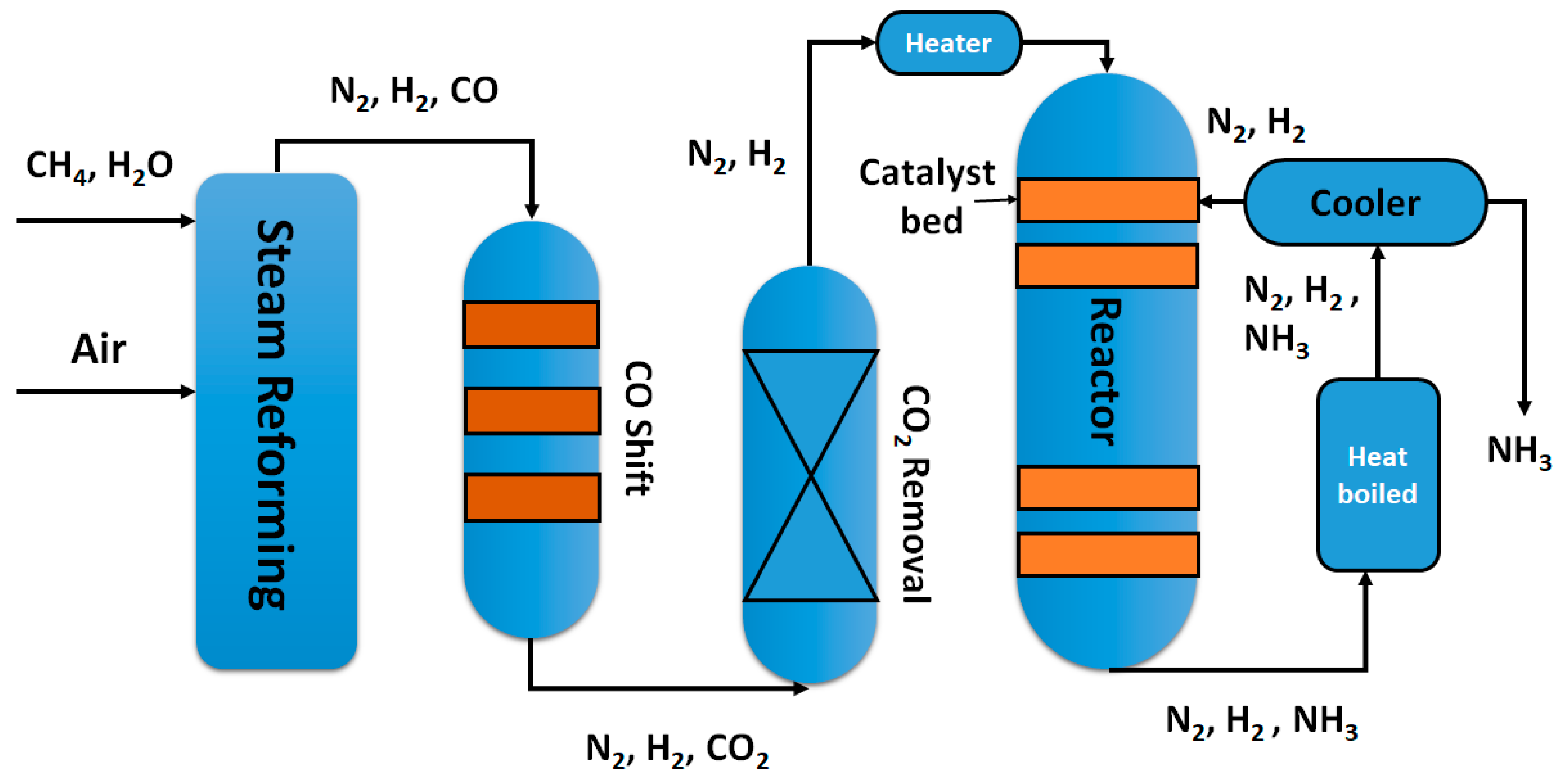
Figure 1. A flow scheme for the Haber-Bosch process.
Catalysts 08 00621 g001
Figure 2. Simulation of semiconductor photocatalysis under light irradiation.
Catalysts 08 00621 g002
Figure 3. (A) High-energy resonant state decay in two possible form: Re-emission of photons or the generation of energetic charge carriers; (B) excitation electron from occupied energy level to a level above the Fermi energy; (C) hot electron overcoming the Schottky barrier and injected to the conduction band of the neighboring semiconductor; (D) plasmon-induce resonance energy transfer. (Reproduced with permission from MDPI [28]).
Catalysts 08 00621 g003
Figure 4. Schematic of semiconductor-based photocatalyst used for the N2 fixation. The redox potentials (Potential (E) vs. Normal Hydrogen Electrode (NHE)) of half reaction water oxidation and dinitrogen protonation are marked on the left.
Catalysts 08 00621 g004
Figure 5. (a,b) TEM images of titanate nanotubes prepared by hydrothermal reaction. © transmission electron microscopy (TEM) images and (d) high resolution transmission electron microscopy (HRTEM) image of 100 × 10−6 Fe3+ doped TiO2. (Reproduced with permission from Elsevier [36]).
Catalysts 08 00621 g005
Figure 6. Scheme (a) catalytic cycle for N2 fixation by Ti3+-containing; Scheme (b) proposed photocatalytic cycle for N2 fixation on the rutile. (Reproduced with permission from ACS [49]).
Catalysts 08 00621 g006
Figure 7. (a) Schematic illustration of the trion induced multi-electron N2 reduction process [50]; (b) Schematic representation of Mo2Fe6S8—Sn2S6 biomimetic chalcogel (FeMoS chalcogel), building block scheme (Mo, blue; Fe, red; S, yellow; Sn, black), and a complete chalcogel shown at right [51]; and (c) Nitrogenase-inspired biomimetic chalcogels [52]. (All the figures are reproduced with permission from the respective publishers).
Catalysts 08 00621 g007
Figure 8. Schematic illustration of the main defects existing in reduced TiO2 upon boron hydride reduction. (VO: Oxygen vacancy; H: Hydride anion in lattice oxygen site; H+: Proton bonding with lattice oxygen.) The trapped electrons are also illustrated. (Reproduced with permission from RSC [58]).
Catalysts 08 00621 g008
Figure 9. (ad) Illustration of the experimental procedures for preparation of bare TiO2, TiO2/Au, TiO2/a-TiO2, and TiO2/Au/a-TiO2 photo-electrodes. (eh) Scanning electron microscopy (SEM) and (il) HRTEM images of photoelectrodes. Key: TiO2/a-TiO2 (a,e,i), bare TiO2 (b,f,j) (inset:selected area electron diffraction (SAED) pattern of the bare TiO2 NR), TiO2/Au (c,g,k), TiO2/Au/a-TiO2 (d,h,l). (Reproduced with permission from Wiley [56]).
Catalysts 08 00621 g009
Figure 10. (A) Schematic illustration of the photocatalytic N2 fixation model in which water serves as both the solvent and proton source, as well as the reversible creation of light-induced oxygen vacancies; (B) Theoretical prediction of N2 activation on the OV of BiOBr (001) surface. (a) Side and (b) top view of (001) surface of BiOBr with an OV. (c) The adsorption geometry of N2 on the OV of BiOBr (001) surface. (d) The charge density difference of the N2-adsorbed (001) surface; (C) Adsorption of N2 on the (001) and (010) facets of BiOCl. (a) Crystal structure of BiOCl and the corresponding cleaved (001) and (010) surface. (b) The terminal end-on adsorption structure of N2 on (001) surface of BiOCl and (c) the side-on bridging adsorption structure of N2 on (010) surface of BiOCl; (D) Schematic illustration of the photocatalytic N2 fixation over Bi5O7I (001) and (100) facers. (Reproduced with permission from the respective publishers; Figure 10A, Figure 10B, Figure 10C and Figure 10D from the References [55], [31], [59], and [60], respectively).
Catalysts 08 00621 g010
Figure 11. The possible nitrogen photofixation process proposed by Ma et al. (Reproduced with permission from Elsevier [68]).
Catalysts 08 00621 g011
Figure 12. The cyano defects were successfully introduced into the g-C3N4 framework by KOH etching and could contribute to improving the nitrogen photofixation ability of g-C3N4. (Reproduced with permission from Elsevier [69]).
Catalysts 08 00621 g012
Figure 13. (a) Nitrogen photofixation performance of the as-prepared catalysts as a function of the sulfur vacancies concentration [70]; (b) The schematic of electron–hole separation and transport at the g-C3N4/ZnMoCdS heterojunction interface [71]. (Reproduced with permission from the respective publishers).
Catalysts 08 00621 g013
Figure 14. (a) the mechanism of photocatalytic N2 fixation over CdS/Pt/RuO2 [75]; (b) M–H bond Strength vs. yield ammonia [76]. (Reproduced with permission from the respective publishers).
Catalysts 08 00621 g014
Figure 15. (a) A schematic illustration of the NH3 synthesis device using a Nb-SrTiO3 photoelectrode loaded with Au nanoparticles [80]; (b) Energy level diagram of the plasmon-induced NH3 synthesis device [81]. (Reproduced with permission from the respective publishers).
Catalysts 08 00621 g015
Figure 16. (a) A schematic illustration the mechanism of Au-Os nanocomposite for NH3 photofixation [79]; (b) Schematic diagram of photochemical nitrogen reduction of Au/bSi/Cr [72]. (Reproduced with permission from the respective publishers).
Catalysts 08 00621 g016
Table 1. Reduction potentials (vs. Standard Hydrogen Electrode (SHE)) of typical hydrogenation reactions relate to the reduction of N2 to NH3.
ReactionE° (V) vs. SHE
N2 + 2H+ + 2e ⇌ N2H2+0.035
N2 + 4H+ + 4e ⇌ N2H4−0.4
N2 + 6H+ + 6e ⇌ 2NH3−1.22
Table 2. Summary of iron active site photocatalysts for the reduction of N2 to NH3.
CatalystLight SourceSacrificial ReagentNH3 RateRef.
0.2% Fe-doped TiO2390–420 nm-10 µmolg−1h−1[42]
0.5% Fe-doped TiO2UV-6 µmolg−1h−1[37]
Fe-doped TiO2254 nmEthanol400 µM·h−1[36]
Partially reduce Fe2O3UV-vis-10 µmolg−1h−1[34]
Fe2O3UV-visEthanol1362.5 µM·h−1[40]
Fe2O3·nH2OVisible-6 µM·h−1[34]
Fe(O)OHVis-9.25 µM·h−1[43]
Fe doped C3N4VisEthanol120 µM·h−1[41]
Fe-load 3D GrapheneUV-24 µmolg−1h−1[44]
Hydrous oxide of Fe and TiVis-22 µM·h−1[45]
Iron loaded bentoniteUV-1.33 µM·h−1[46]
Iron titanate thin film>320 nmEthanol0.57 µM·h−1cm−2[38]
Table 3. Summary of oxide catalysts for the photoreduction of N2 to NH3.
CatalystLight SourceSacrificial ReagentNH3 RateRef
BiOBr nanosheetsUV-Vis/Vis-104.2 µmolg−1h−1[31]
Bi5O7Br nanotubesVis-1.38 mmol·g1h−1[55]
TiO2/Au/a-TiO2Vis-13.4 nmol cm−2h−1[56]
BiO quantum dotsUV-Vis-1226 µmolg−1h−1[57]
Reduced TiO2Infrared light-3.33 µmolg−1h−1[58]
Rutile TiO2λ > 280 nm2-Propanol16.67µM·g1h−1[49]
BiOCl nanosheetsSolar LightEthanol45 µM·h−1[59]
Bi5O7I nanosheets280–800 nmEthanol120 µM·h−1[60]
CuCr–LDHVis-57.1 μmolg−1h−1[61]
Hydrogenated Bi2MoO6Solar light-1.3 mmol·g−1h−1[62]