Article

Natural Hematite as a Low-Cost and Earth-Abundant Cathode Material for Performance Improvement of Microbial Fuel Cells

The Key Laboratory of Orogenic Belts and Crustal Evolution, School of Earth and Space Sciences, Peking University, Beijing 100871, China
*
Author to whom correspondence should be addressed.
These authors contributed equally to this work.
Catalysts 2016, 6(10), 157; https://doi.org/10.3390/catal6100157
Submission received: 31 August 2016 / Revised: 2 October 2016 / Accepted: 11 October 2016 / Published: 14 October 2016
(This article belongs to the Special Issue Microbial Fuel Cells)

Abstract

:
Developing cheap electrocatalysts for cathodic oxygen reduction in neutral medium is a key factor for practical applications of microbial fuel cells (MFCs). Natural hematite was investigated as a low-cost cathode to improve the performance of microbial fuel cells (MFCs). With hematite-coated cathode, the cell current density stabilized at 330.66 ± 3.1 mA·m−2 (with a 1000 Ω load) over 10 days under near-neutral conditions. The maximum power density of MFC with hematite cathode reached to 144.4 ± 7.5 mW·m−2, which was 2.2 times that of with graphite cathode (64.8 ± 5.2 mW·m−2). X-ray diffraction (XRD), Raman, electrode potential analysis, and cyclic voltammetry (CV) revealed that hematite maintained the electrode activities due to the stable existence of Fe(II)/Fe(III) in mineral structure. Electrochemical impedance spectroscopy (EIS) results indicated that the cathodic electron transfer dynamics was significantly improved by using hematite to lower the cathodic overpotential. Therefore, this low-cost and earth-abundant natural mineral is promised as an effective cathode material with potential large-field applications of MFCs in future.

Graphical Abstract

1. Introduction

Microbial fuel cells (MFCs) are devices that use bacteria oxidize organic matter to generate current, in which oxygen is the most widely used cathode electron acceptor. However, the cathodic reaction is always a key limiting factor for improving the cell performance [1,2,3]. To date, a variety of electrocatalysts have been developed. Platinum based materials are the most commonly used catalysts because of its high catalytic activity [4,5,6]. However, such precious-metal catalysts are high-cost, scarce, and have limited stability. In recent years, the synthesis of electrocatalysts containing non-precious metals (e.g., Fe and Co) have been extensively investigated in MFCs for improving cathodic reactivity. Promising results in terms of oxygen reduction reaction activity were non-precious metals linked with organics N4-chelating ligands and their polymeric derivatives [7,8,9,10], such as metals tetramethoxyphenylporphyrin (TMPP), CoTMPP, FeCoTMPP, ClFeTMPP, and metals phthalocyanine (Pc), FePc, CoPc, CoNPc, FeCuPc, etc. [11,12,13,14,15,16,17]. Although these catalysts have excellent performance, all of these materials should be prepared at a high temperature with inert atmosphere [8,11,12,13], which makes the preparation more complicated and requires an extra cost. Moreover, these catalysts can be poisoned by certain chemical species in the water, such as sulfides [18].
The use of biocathodes, as alternatives to noble and nonnoble metal cathode catalysts has been proposed recently [19,20]. In general, biocathodes can be classified as aerobic and anaerobic biocathodes; MnO2 and manganese oxidizing bacteria-Leptothrix discophora was investigated as aerobic biocathodes and the maximum power output increased by more than 40 times [21]. In the absence of oxygen, nitrate and sulfate have been studied as possible terminal electron acceptors in biocathodes of MFCs [19]. Unfortunately, the bacterial electron-transfer mechanisms in the cathode have not been fully understood, although biocathodes in MFC have some promise, more significant research is required for their practical and economic development.
Furthermore, other catalysts have also been reported to enhance cathode performance and reduce cathode costs. Carbon nanotube (CNT) and graphene are emerging inorganic membrane material used in electrochemical filter wastewater treatment system for combined advantageous properties of stability, exibility, chemical resistivity, and large specific surface area [22,23,24,25,26]. Previous studies demonstrated that both Co/Fe/N/CNT, nitrogen-doped graphene, and activated carbon exhibited slightly higher current density and better power output compared with the Co/Fe/N/graphite and commercial Pt/carbon electrode, but complicated preparation process was required [5,6,27,28].
In addition, some metal oxides, including MnO2, PbO2, and TiO2, have been used for cathode catalysts [29,30,31,32]. Roche et al. employed the manganese oxide (MnOx/C) as the cathode catalyst and Li et al. investigated the performances of cryptomelane-type octahedral molecular sieve with cobalt, copper, and cerium doped catalysts [29,30]. When PbO2 was used as a catalyst power generation was promoted but chamber solutions found dissolution of Pb [31]. Lu et al. tested the natural rutile (a semiconductor mineral) as a novel cathode catalyst for MFCs, and proved it may be an alternative under light [32]. Due to the convenient access, abundant production, and environmental friendly attributes, natural iron-containing minerals may be considered as alternatives for cathode materials.
According to USGS (The US Geological Survey) data, the world iron ore resources are estimated to be greater than 800 billion tons [33]. Among these iron-containing minerals, hematite is the most widespread type on Earth. Nowadays, the price of natural hematite was less than $0.1 per kilogram [34], which is much lower than other synthetic materials. Factually, nanostructured hematite anodes have been previously used in MFCs to promote the extracellular electron transfer [35,36,37,38,39,40]. Unfortunately, in these systems, microorganisms directly use hematite as electron acceptors, thus leading to the reductive dissolution of hematite [37,38]. Therefore, if hematite is used in the cathodic chamber, the consumption of the anode material and the possible release of metal ions can be avoided.
In this study, a natural hematite cathode was prepared and equipped into a MFC system under near-neutral conditions. The cell performances and electrochemical properties of the MFC-hematite system were discussed and provided the detailed electrode reaction mechanisms. Given the improvement of power output in this MFC-hematite system, natural hematite is believed to be an efficient and low-cost cathode material with potential applications in large-scale field conditions.

2. Results and Discussion

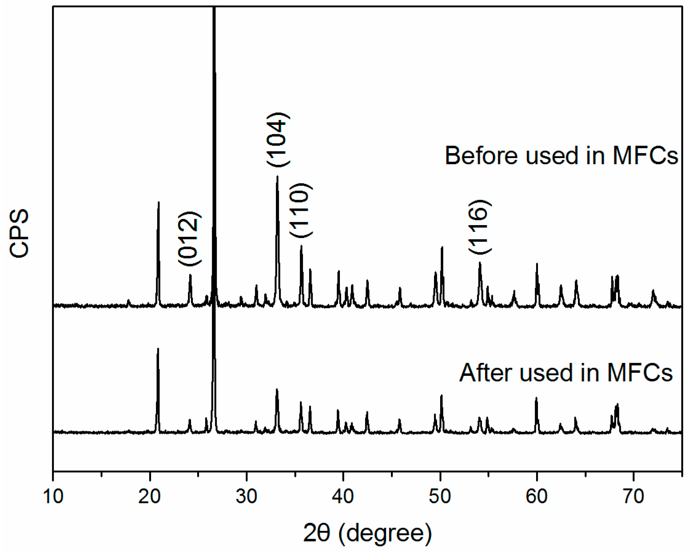
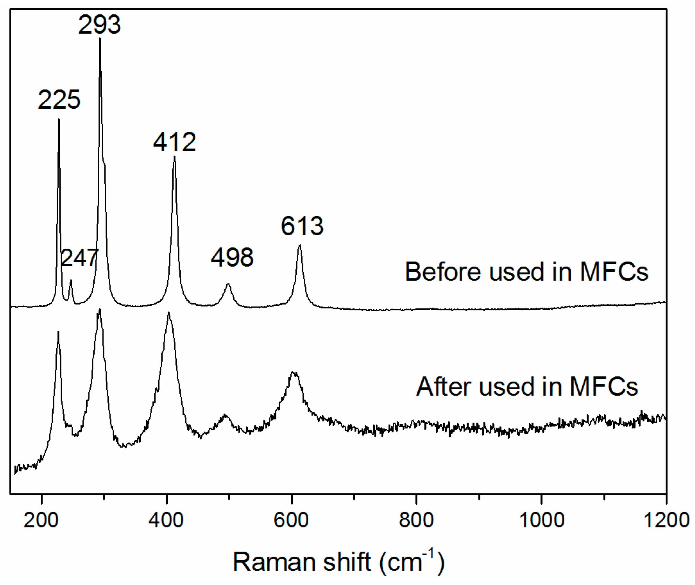
2.1. XRD and Raman Characterization of Hematite

The powder X-ray diffraction (XRD) patterns for nature hematite are shown in Figure 1. As can be seen, several diffraction peaks were observed at 2θ, namely at 24.14°, 33.15°, 35.61°, and 54.1°, which were assigned to the (012), (104), (110), and (116) planes of a crystalline hematite [41]. Three diffraction peaks appeared at 20.86°, 26.64°, and 50.13° were assigned to the (100), (101), and (112) planes of quartz (PDF #46-1045). This observation suggested that the main minerals in Lingshou hematite deposit sample are hematite and quartz. After the hematite electrode was used in the MFCs, no new peaks appeared and the XRD pattern of quartz did not exhibit any change. However, peak intensities of hematite were relatively decreased, which may be due to the loss of hematite in sample or a decrease in the crystallization of hematite.
Hematite belongs to the D 3 d 6 crystal space group and seven phonon lines are expected in the Raman spectrum, namely two A1g modes (225 and 498 cm−1) and five Eg modes (247, 293, 299, 412, and 613 cm−1) [42]. Raman spectra of our sample showed six major vibrational features corresponding to hematite, which could be recognized at 225, 247, 293, 412, 493, and 613 cm−1 (Figure 2). After the hematite electrode was used in the MFCs, no new peak was observed in the Raman spectrum, therefore no new mineral phase formed. In the diffraction pattern of hematite, the peak intensities are relatively low and the width of its diffraction peaks is broad almost two times more than before, which indicated a lower crystallization of hematite.

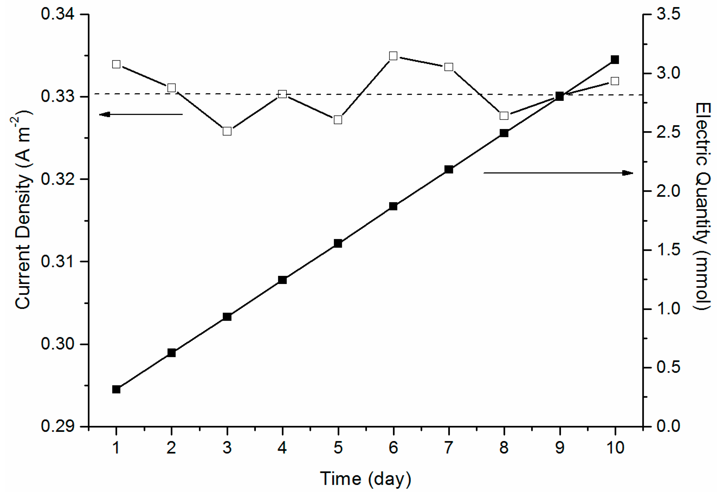
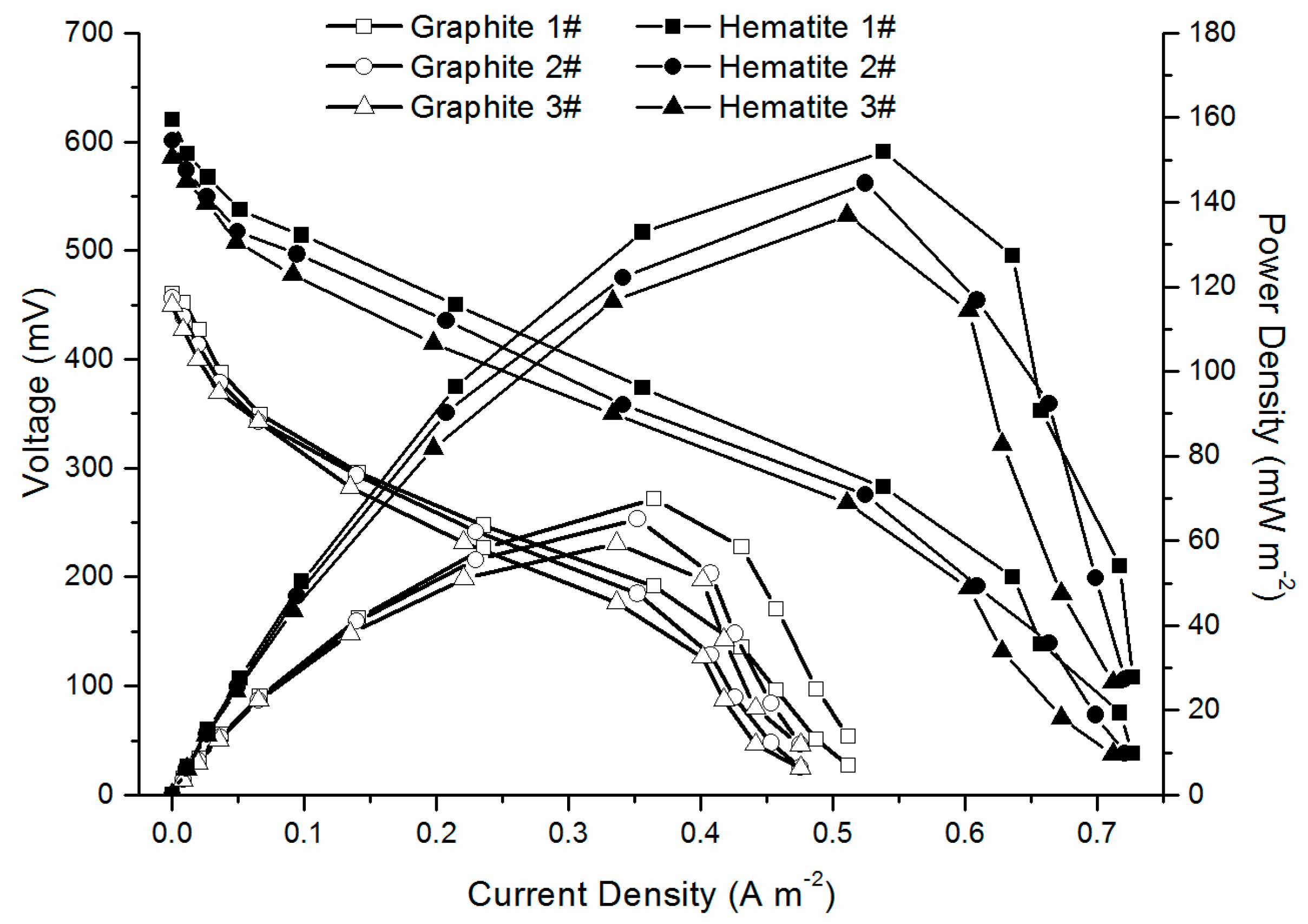
2.2. MFC Performance

The cell with hematite cathode exhibited excellent stability in fed-batch cultivation. In one typical batch, the system current was maintained at 330.66 ± 3.1 mA·m−2 for 10 days after fresh medium alternation, and the electric quantity presented a lineal accumulation (R2 = 1.00) as shown in Figure 3. The modified ferrozine method was used to determine the concentration of Fe2+ in the cathode chamber, however no soluble iron ions were detected in the cathode chamber. Therefore, such superior long-term stability of natural hematite cathode indicated the mineral was not consumed in the cathode chamber. XRD and Raman spectrums results indicated that hematite maybe act as a mediator with iron ions released from the decomposition of hematite and quickly forming new mineral at the cathode. Finally, the dissolved oxygen was considered to be the terminal electron acceptor in the MFC-hematite system.
The performance of MFCs was quantified via polarization and power density curves in three typical batch cultivations (Figure 4). The maximum power density of MFC with a hematite cathode was 144.4 ± 7.5 mW·m−2, while it was only 64.8 ± 5.2 mW·m−2 in the control experiment with a graphite cathode (Table 1). In an additional sterile control experiment, the current density was lower than 0.21 μA·cm−2 at 1000 Ω and would not remain stable. The results verified hematite itself could not establish effective electron transfer. Therefore, the cell performance was still based on anodic microbial extracellular electron transfer as in a conventional MFC.
The improved power density implied that more efficient cathodic reactions happened with hematite cathode (although expensive catalysts have better performance). The value of hematite cathode was close to recent studies of different type of catalysts. The maximum power of Co-naphthalocyanine (CoNPc/C) was 64.7 mW·m−2 at 0.25 mA as compared with 81.3 mW·m−2 of Pt/C, 29.7 mW·m−2 of NPc/C, and 9.3 mW·m−2 of carbon black when the cathodes were implemented in H-type MFCs [13]. In addition, the maximum power density of plain carbon paper was 67 mW·m−2, 77 mW·m−2 for carbon felt, and 124 mW·m−2 (with Pt for 0.2 mg·cm−2) for platinum-coated carbon paper [5]. As far as iron-based materials performance is concerned, carbon black/iron phthalocyanine (FePc) (140.30 ± 38.60 mW·m−2) and iron chelates/carbon nanotube (127 ± 0.9 mW·m−2) [43,44] were similar with hematite. Moreover, hematite cathode compared to similar values with manganese oxides (35–180 mW·m−2) [29,30] carbon felt (77 mW·m−2), platinum-coated carbon paper (124 mW·m−2, 0.2 mg·Pt·cm−2) [5], and lower values with PbO2 (<80 mW·m−2) [31]. The comparison demonstrated that this natural mineral-hematite could be considered as an efficient and readily available substitute for artificial cathode catalysts without the need for complex composites. Notably, the preparation of hematite electrode was simple and the material was more easily available than any existing artificial cathode material.
Potential curves of anode and cathode were obtained under actual operating condition in one typical batch (Figure 5). For the microbial anode, the initial potential was about −460 mV vs. SCE (saturated calomel electrode) under open circuit, which was consistent with previously reported MFCs using acetate as the electron donor [45]. Also, the potential presented a linear increase because of ohmic polarization domination. Significant potential turning was observed when the current density was limited by mass transport on the electrode surface. With a hematite cathode, the turning position positively shifted from 370 to 530 mA·m−2, which suggested enhanced anodic bio-activities. For the cathode, potentials dropped from the open circuit condition due to the activation energy loss of oxygen reduction, and no mass transport limitation was observed. The hematite cathode maintained higher potential than graphite. The cell voltage was calculated by Ecell = EcathodeEanode, thus, a MFC-hematite system have a higher voltage. Such cathodic reaction properties demonstrated that hematite was an efficient cathode material for electron accepting.

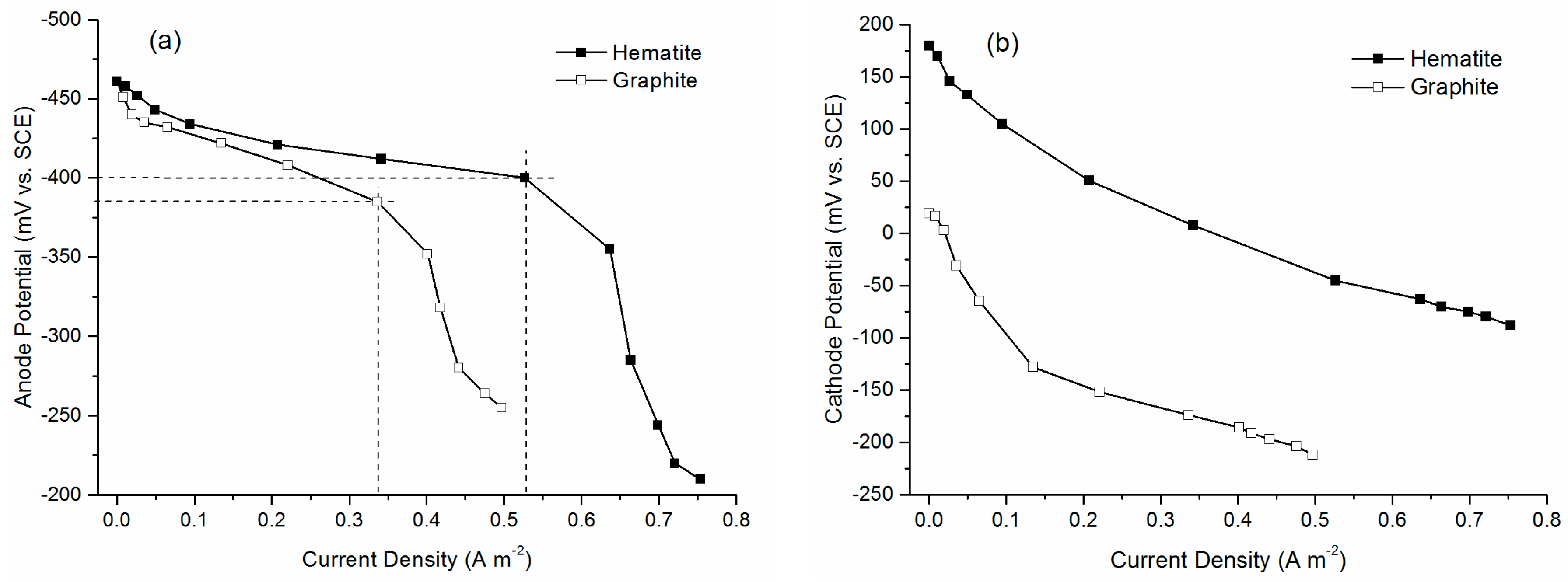
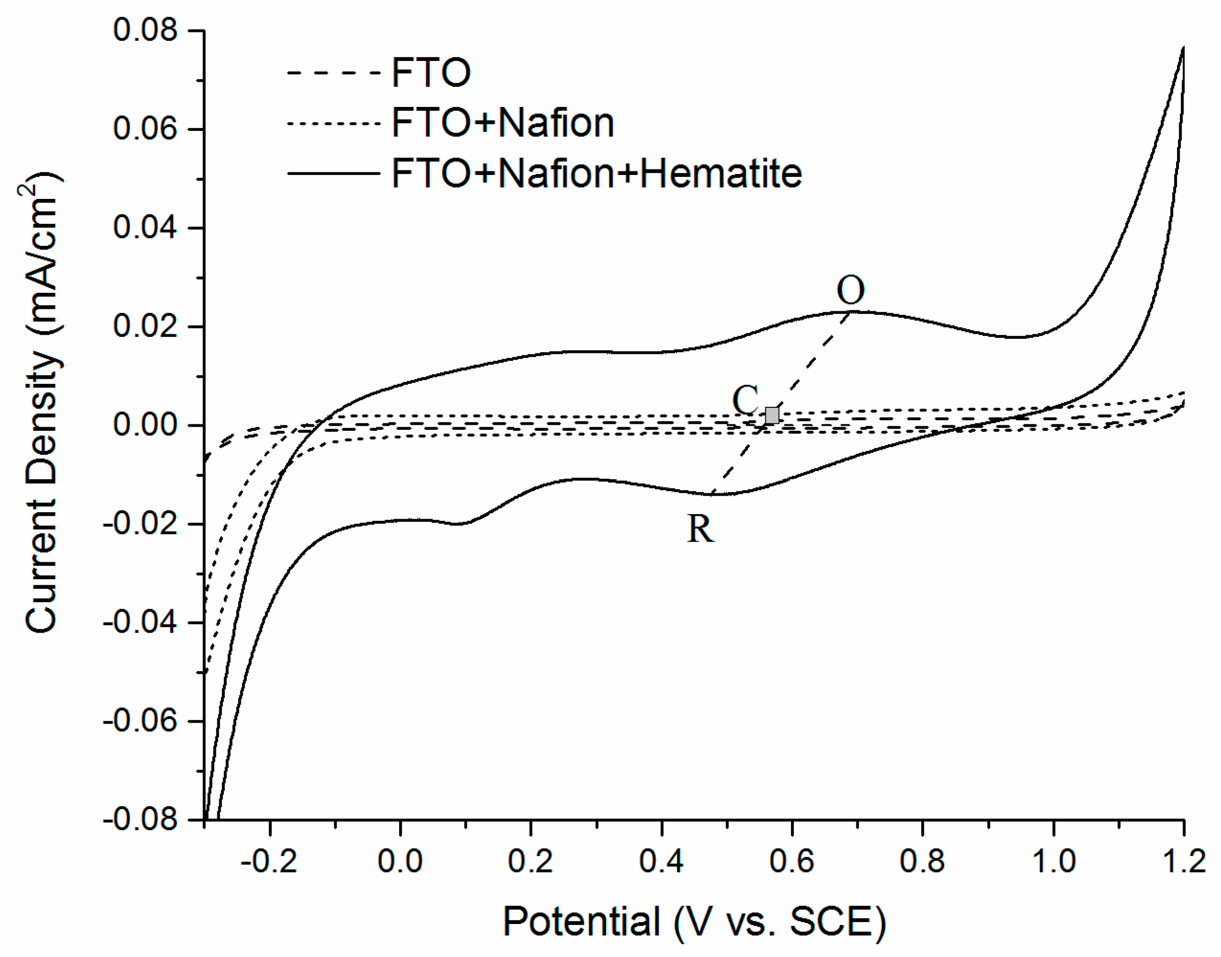
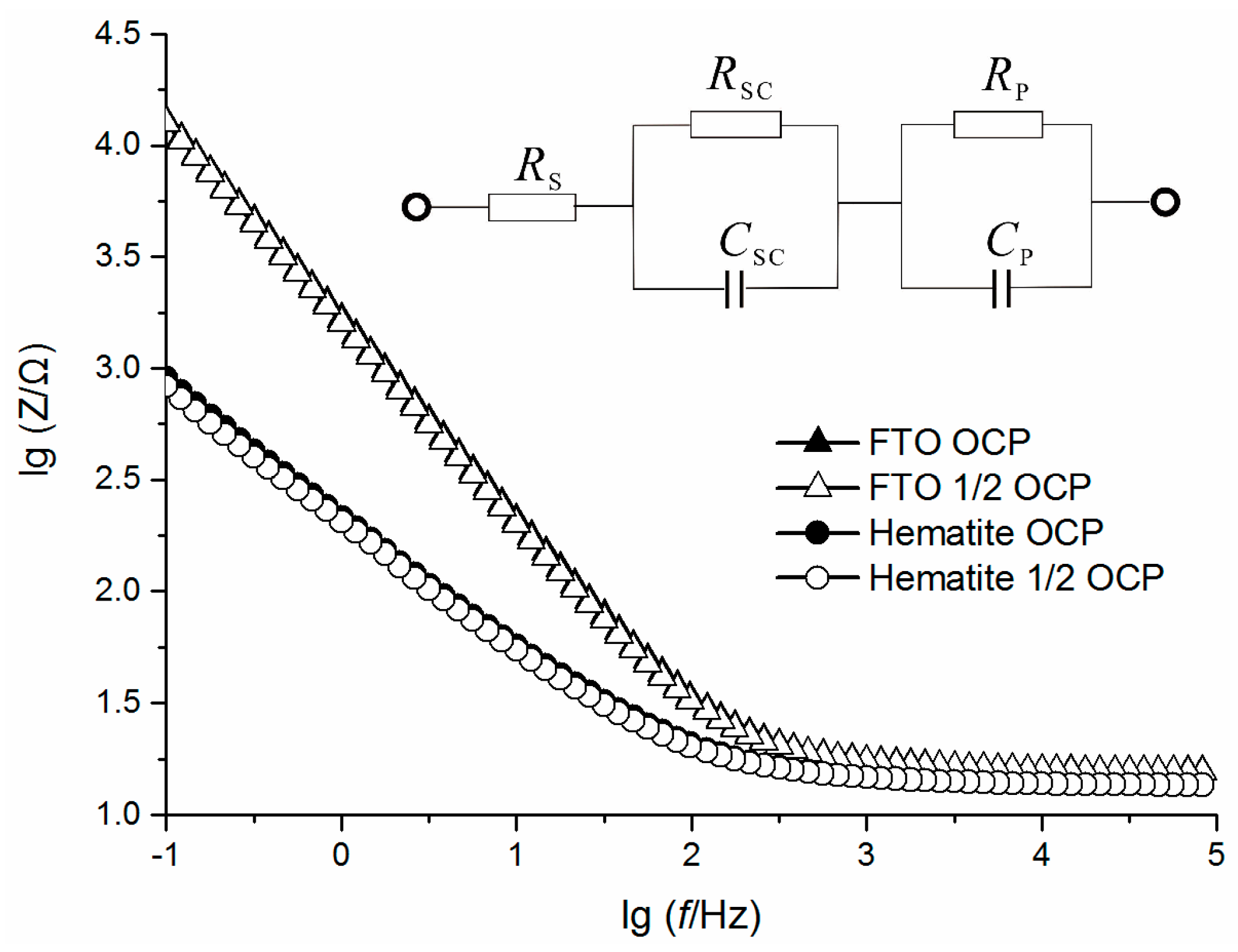
2.3. Electrochemical Characterization

Furthermore, a typical three-electrode electrochemical cell was used to analyze the detailed electrode reactions. Cyclic voltammetry (CV) curves showed that with a hematite-FTO (Fluorine-doped tin oxide) electrode, an interesting redox pair which was located at 0.486 V (R) and 0.694 V (O) vs. SCE, with E1/2(C) at 0.590 V vs. SCE observed (Figure 6). This quasi-reversible reaction was attributed to the redox of Fe(II)/Fe(III) [46]. As the anode potential was usually below −400 mV vs. SCE in MFCs [47] and the potential of c-type cytochromes on Geobacteracea outer membrane was about −450 mV vs. SCE [48]. The redox pair (R and O) was located between the microbial oxidation and the oxygen reduction potentials [49]. Hence, hematite was found to act as an electron mediator or catalyst for enhancing the terminal oxygen reduction. The results indicated that hematite had excellent electrochemical activities and was an efficient cathode material for high cell performance, while the cost was extra low, as previously mentioned.
The above-mentioned mechanisms were quantified by further electrochemical impedance spectroscopy (EIS) analysis with a three-major-part equivalent circuit (EC) to elucidate the electrochemical processes at the electrolyte/electrode interface [50] (Figure 7). The EC contained a solution resistance (Rs), a space charge region with Csc and Rsc in parallel, and a surface layer with Cp and Rp in parallel. We focused on the fitting results of Rp and Rsc (Table 2) with the one-time constant model (OTCM), which represented the resistive behaviors of the surface layer and the space charge region, respectively. Here the Rp of hematite was 42.6 Ω smaller than FTO because the hematite film improved the specific surface area of the electrode. The remarkable change was that Rsc had dramatically decreased over 97% with hematite. This proved to be a much more effective electron exchange in the space charge region, and led to the direct improvement of the electrode redox activity.
Based on the experimental results mentioned above, a possible reaction mechanism of promoting oxygen reduction in MFCs by natural hematite is proposed (Scheme 1). Comprehensive analysis of CV and EIS results indicated hematite as a superior electrode material due to its Fe(II)/Fe(III) redox activity and low resistance at the reaction interface. The redox pair of hematite was located between the microbial oxidation and the oxygen reduction potentials. Therefore, the electron transfer process from the anode could be promoted. Meanwhile, the cathodic electron transfer dynamics was significantly improved by using hematite to lower the overpotential of the cathode. Finally the performance of the entire cell was improved.

3. Materials and Methods

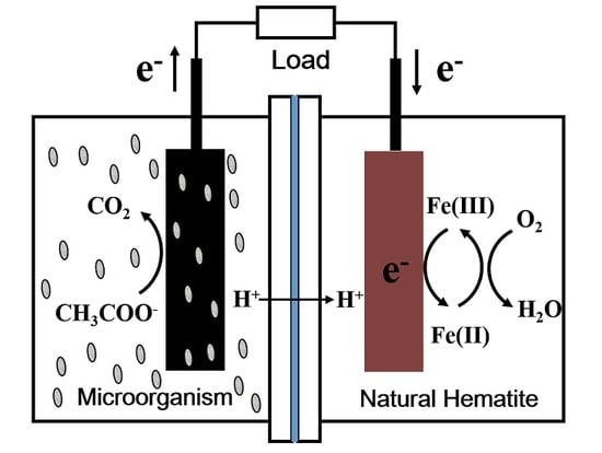
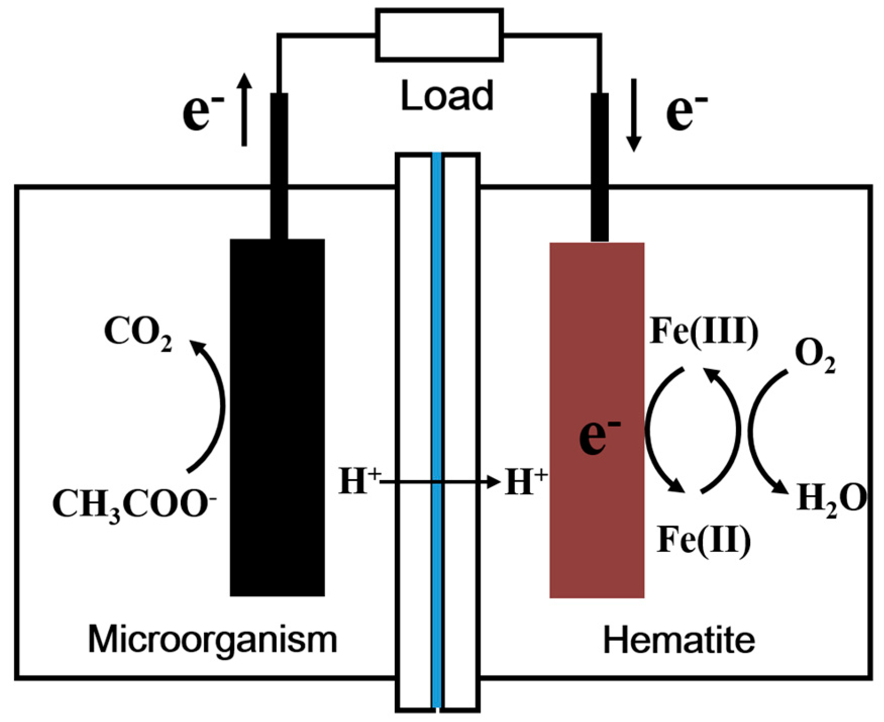
3.1. MFC Configuration

The MFC-hematite system was based on a conventional dual-chambered MFC. The two chambers (each with a liquid volume of 40 mL) were separated by a cation exchange membrane (CEM, CMI-7000, Ultrex, GlenRock, NJ, USA) with an area of 35 cm2. Both the cathode and anode chambers contained saturated calomel reference electrodes to determine individual electrode potentials. Electrodes were made of polished graphite with a working area of 16 cm2 (Shanghai Hongfeng Industrial Co., Ltd., Shanghai, China) and pretreated in 1.0 M HCl and then 1.0 M NaOH for 1 h each to ensure a clean surface. The anode chamber was filled with a culture medium containing: 0.1 g/L of KCl, 0.5 g/L of NH4Cl, 0.1 g/L of MgCl2, 0.1 g/L of CaCl2, 0.3 g/L of KH2PO4, 2.5 g/L of NaHCO3, and 8.20 g/L of CH3COONa. All reagents used in this study were of analytical grade and purchased from Beijing Chemical Reagent Corporation (Beijing, China). Microorganisms were collected from red-soil MFCs in our lab, which were inoculated to 10% (v/v) and kept in fed-batch cultivation. The cathode chamber was filled with 1 M KCl solution as the electrolyte and aerated. The solution was near neutral (pH 5.9 ± 0.1). The cell was operated daily with an external resistance of 1000 Ω. All of the experiments were carried out at a constant temperature and humidity incubator (30 ± 1 °C).

3.2. Natural Hematite Characterization

Natural hematite was sampled from the Lingshou hematite mineral deposit (Shijiazhuang, China). The samples were ground in a mortar and sieved through a 400 mesh sieve with an average particle size of approximately 40 μm. Powder XRD data was obtained with an X-ray diffractometer (Rigaku Dmax-2400, Rigaku Corporation, Tokyo, Japan) equipped with Cu Kα radiation (λ = 0.15406 nm). The instrument was operated at a tube voltage of 40 kV and a tube current of 40 mA. Intensities were measured at 2θ = 3°–75° with 0.017° two-theta steps and a count time of 0.3 s per step. The resulting XRD data were analyzed with the Powder Diffraction Standard (JCPDS) database.
Raman spectra were measured using a Renishaw inVia Reflex system (Renishaw inVia Reflex, Wotton-under-Edge, Gloucestershire, UK) equipped with a 532 nm laser and a long working-distance 50× objective. The laser intensity was 50% and the diameter of the beam spot was 1 μm. To have a high signal-to-noise ratio, each Raman spectrum was the average of 10 successive scans obtained at a spectral resolution of 1 cm−1. The frequency stability and the accuracy of the apparatus were checked by recording the Raman spectrum of silicon.

3.3. Hematite Electrode Preparation and Iron Determination

The MFC hematite cathode was made by smearing the hematite (200 mg) mixed with ethanol solution (2 mL) on both sides of a polished graphite electrode (3.0 × 3.5 cm2 and 0.5 cm thickness) which were cleaned by soaking in 1.0 M HCl followed by 1.0 M NaOH, each for 1 h. Nafion solution (20 μL) was then added with a few drops, therefore creating a rubberlike paste that was rolled into a film on the graphite surface. The coated cathode was allowed to air-dry overnight.
The electrochemical electrode was called hematite-FTO electrode, which was made by dropwise adding mineral paste mixed with hematite powder (40 mg), anhydrous ethanol (200 μL), and Nafion (10 μL) to the FTO (Fluorine-doped tin oxide) conductive side. Before use, the FTO was cleaned by sonication in acetone, ethanol, and distilled water for 30 min each. The mineral electrode was used for electrochemical measurements after a 12 h air-dry.
The iron concentration was determined by a modified Ferrozine method. First, stock standard solution of iron, concentration 25.0 μg/mL was prepared in the following way: 0.1755 g of ammonium iron sulphate hexahhydrate (NH4)2Fe(SO4)2·6H2O was dissolved in water in a 1000 mL volumetric flask, 10 mL of concentrated sulphuric acid was added, and water was added to the mark. A working curve was obtained by using a series of standard iron solutions from 0 to 5 mg/L, and 1 mL of hydroxylamine hydrochloride (10%) was added to a 50 mL colorimetric tube, vortexed for 10 s, and incubated at room temperature for 15 min. Subsequently, 2 mL of ferrozine (0.05%) and 5 mL of 1.0 M CH3COONa solution were added, followed by adding water to the mark. The absorbance at 510 nm was measured by spectrophotometer (Evolution 220, Thermo Scientific, Waltham, MA, USA) and correlated with the known Fe2+ concentration to plot a working curve.

3.4. Electricity and Electrochemical Measurement Methods

The cell voltage was recorded by a datalogger (ADC-16, Pico Technology, Cambridgeshire, UK). Polarization and power density curves were calculated under different resistance values from an open circuit to 10 Ω. For every resistance change, the cell was stabilized for at least 20 min to reach a steady state. Electrode potentials were recorded simultaneously by a digital voltmeter (UT-33B, Shenzhen UNI-T, Shenzhen, China), which were relative to a saturated calomel electrode (SCE, 0.242 V vs. normal hydrogen electrode, 25 °C). CV and EIS were performed by a potentiostat (CHI760E, Shanghai Chenhua Instrument, Shanghai, China) with 1 M KCl aqueous solution as the electrolyte and used a conventional three electrode system consisting of hematite-FTO electrode as the working electrode, a Pt sheet as the auxiliary electrode and a SCE reference electrode. The performances of natural hematite-FTO electrode were compared with an uncoated FTO electrode as a conventional cathode used in MFCs.

4. Conclusions

As a low-cost natural mineral, natural hematite was prepared and used as a cathode material in MFCs in order to improve cell performances. The MFCs with natural hematite cathodes exhibited long-term stability with current density of 330.66 ± 3.1 mA·m−2 at 1000 Ω for 10 days in one batch cultivation. The maximum power density of MFC-hematite was 144.4 ± 7.5 mW·m−2, which was 2.2 times that of MFCs with a graphite cathode. Hematite offered structural Fe(II)/Fe(III) redox reactivity as a cathode catalyst for enhancing oxygen reduction in MFCs. Further studies plan to optimize the cell configuration and to investigate the usages of various natural mineral cathodes in MFCs.

Acknowledgments

This research was supported by the National Basic Research Program of China (Program No. 2014CB846001), the Natural Science Foundation of China (Grant No. 41230103, 41272003 & 41402032), and the China Postdoctoral Science Foundation funded project (Grant No. 2014M550552).

Author Contributions

Guiping Ren and Hongrui Ding contributed equally to this work. Guiping Ren and Hongrui Ding conceived and designed the experiments; Guiping Ren performed the experiments; Guiping Ren and Hongrui Ding analyzed the data; Guiping Ren and Hongrui Ding wrote the paper; Yan Li performed revisions and gave final approval of the version to be published; Anhuai Lu participated in the design of the study and funded the study.

Conflicts of Interest

The authors declare no conflict of interest.

References

  1. Logan, B.E.; Hamelers, B.; Rozendal, R.; Schröder, U.; Keller, J.; Freguia, S.; Aelterman, P.; Verstraete, W.; Rabaey, K. Microbial fuel cells: Methodology and technology. Environ. Sci. Technol. 2006, 40, 5181–5192. [Google Scholar] [CrossRef] [PubMed]
  2. Lovley, D.R. Bug juice: Harvesting electricity with microorganisms. Nat. Rev. Microbiol. 2006, 4, 497–508. [Google Scholar] [CrossRef] [PubMed]
  3. Tender, L.M.; Reimers, C.E.; Stecher, H.A.; Holmes, D.E.; Bond, D.R.; Lowy, D.A.; Pilobello, K.; Fertig, S.J.; Lovley, D.R. Harnessing microbially generated power on the seafloor. Nat. Biotechnol. 2002, 20, 821–825. [Google Scholar] [CrossRef] [PubMed]
  4. Oh, S.; Min, B.; Logan, B.E. Cathode performance as a factor in electricity generation in microbial fuel cells. Environ. Sci. Technol. 2004, 38, 4900–4904. [Google Scholar] [CrossRef] [PubMed]
  5. Deng, Q.; Li, X.; Zuo, J.; Ling, A.; Logan, B.E. Power generation using an activated carbon fiber felt cathode in an upflow microbial fuel cell. J. Power Sources 2010, 195, 1130–1135. [Google Scholar] [CrossRef]
  6. Deng, L.; Zhou, M.; Liu, C.; Liu, L.; Liu, C.; Dong, S. Development of high performance of Co/Fe/N/CNT nanocatalyst for oxygen reduction in microbial fuel cells. Talanta 2010, 81, 444–448. [Google Scholar] [CrossRef] [PubMed]
  7. Jasinski, R. A new fuel cell cathode catalyst. Nature 1964, 201, 1212–1213. [Google Scholar] [CrossRef]
  8. Hijazi, I.; Bourgeteau, T.; Cornut, R.; Morozan, A.; Filoramo, A.; Leroy, J.; Derycke, V.; Jousselme, B.; Campidelli, S. Carbon nanotube-templated synthesis of covalent porphyrin network for oxygen reduction reaction. J. Am. Chem. Soc. 2014, 136, 6348–6354. [Google Scholar] [CrossRef] [PubMed]
  9. Birry, L.; Mehta, P.; Jaouen, F.; Dodelet, J.P.; Guiot, S.R.; Tartakovsky, B. Application of iron-based cathode catalysts in a microbial fuel cell. Electrochim. Acta 2011, 56, 1505–1511. [Google Scholar] [CrossRef]
  10. HaoYu, E.; Cheng, S.; Scott, K.; Logan, B.E. Microbial fuel cell performance with non-Pt cathode catalysts. J. Power Sources 2007, 171, 275–281. [Google Scholar] [CrossRef]
  11. Cheng, S.A.; Liu, H.; Logan, B.E. Cathode materials and polymer binders as factors that affect power densities in microbial fuel cells. Environ. Sci. Technol. 2006, 40, 364–369. [Google Scholar] [CrossRef] [PubMed]
  12. Zhao, F.; Harnisch, F.; Schröder, U.; Scholz, F.; Bogdanoff, P.; Herrmann, I. Application of pyrolysed iron(II) phthalocyanine and CoTMPP based oxygen reduction catalysts as cathode materials in microbial fuel cells. Electrochem. Commun. 2005, 7, 1405–1410. [Google Scholar] [CrossRef]
  13. Kim, J.R.; Kim, J.Y.; Han, S.B.; Park, K.W.; Saratale, G.D.; Oh, S.E. Application of Co-naphthalocyanine (CoNPc) as alternative cathode catalyst and support structure for microbial fuel cells. Bioresour. Technol. 2011, 102, 342–347. [Google Scholar] [CrossRef] [PubMed]
  14. Lu, G.; Zhu, Y.; Xu, K.; Jin, Y.; Ren, Z.J.; Liu, Z.; Zhang, W. Metallated porphyrin based porous organic polymers as efficient electrocatalysts. Nanoscale 2015, 7, 18271–18277. [Google Scholar] [CrossRef] [PubMed]
  15. Lu, G.; Yang, H.; Zhu, Y.; Huggins, T.; Ren, Z.J.; Liu, Z.; Zhang, W. Synthesis of a conjugated porous Co (II) porphyrinylene–ethynylene framework through alkyne metathesis and its catalytic activity study. J. Mater. Chem. A 2015, 3, 4954–4959. [Google Scholar] [CrossRef]
  16. Lu, G.; Zhu, Y.; Lu, L.; Xu, K.; Wang, H.; Jin, Y.; Ren, Z.J.; Liu, Z.; Zhang, W. Iron-rich nanoparticle encapsulated, nitrogen doped porous carbon materials as efficient cathode electrocatalyst for microbial fuel cells. J. Power Sources 2016, 315, 302–307. [Google Scholar] [CrossRef]
  17. Ahmed, J.; Yuan, Y.; Zhou, L.; Kim, S. Carbon supported cobalt oxide nanoparticles-iron phthalocyanine as alternative cathode catalyst for oxygen reduction in microbial fuel cells. J. Power Sources 2012, 208, 170–175. [Google Scholar] [CrossRef]
  18. Freguia, S.; Rabaey, K.; Yuan, Z.; Keller, J. Non-catalyst cathodic oxygen reduction at graphite granules in microbial fuel cells. Electrochim. Acta 2007, 53, 598–603. [Google Scholar] [CrossRef]
  19. He, Z.; Angenent, L.T. Application of bacterial biocathodes in microbial fuel cells. Electroanalysis 2006, 18, 2009–2015. [Google Scholar] [CrossRef]
  20. Clauwaert, P.; Van der Ha, D.; Boon, N.; Verbeken, K.; Verhaege, M.; Rabaey, K.; Verstraete, W. Open air biocathode enables effective electricity generation with microbial fuel cells. Environ. Sci. Technol. 2007, 41, 7564–7569. [Google Scholar] [CrossRef] [PubMed]
  21. Rhoads, A.; Beyenal, H.; Lewandowski, Z. Microbial fuel cell using anaerobic respiration as an anodic reaction and biomineralized manganese as a cathodic reactant. Environ. Sci. Technol. 2005, 39, 4666–4671. [Google Scholar] [CrossRef] [PubMed]
  22. Liu, Y.; Lee, J.H.D.; Xia, Q.; Ma, Y.; Yu, Y.; Yung, L.Y.L.; Zhou, Z. A graphene-based electrochemical filter for water purification. J. Mater. Chem. A 2014, 2, 16554–16562. [Google Scholar] [CrossRef]
  23. Liu, Y.; Xie, J.; Ong, C.N.; Vecitis, C.D.; Zhou, Z. Electrochemical wastewater treatment with carbon nanotube filters coupled with in situ generated H2O2. Environ. Sci. Water Res. Technol. 2015, 1, 769–778. [Google Scholar] [CrossRef]
  24. Iijima, S. Helical microtubules of graphitic carbon. Nature 1991, 354, 56–58. [Google Scholar] [CrossRef]
  25. Lee, S.M.; Lee, S.C.; Jung, J.H.; Kim, H.J. Pore characterization of multi-walled carbon nanotubes modified by KOH. Chem. Phys. Lett. 2005, 416, 251–255. [Google Scholar] [CrossRef]
  26. Novoselov, K.S.; Geim, A.K.; Morozov, S.V.; Jiang, D.; Zhang, Y.; Dubonos, S.V.; Grigorieva, I.V.; Firsov, A.A. Electric field effect in atomically thin carbon films. Science 2004, 306, 666–669. [Google Scholar] [CrossRef] [PubMed]
  27. Liu, Y.; Liu, H.; Wang, C.; Hou, S.X.; Yang, N. Sustainable energy recovery in wastewater treatment by microbial fuel cells: Stable power generation with nitrogen-doped graphene cathode. Environ. Sci. Technol. 2013, 47, 13889–13895. [Google Scholar] [CrossRef] [PubMed]
  28. Zhang, B.; Wen, Z.; Ci, S.; Mao, S.; Chen, J.; He, Z. Synthesizing nitrogen-doped activated carbon and probing its active sites for oxygen reduction reaction in microbial fuel cells. ACS Appl. Mater. Interfaces 2014, 6, 7464–7470. [Google Scholar] [CrossRef] [PubMed]
  29. Roche, I.; Katuri, K.; Scott, K. A microbial fuel cell using manganese oxide oxygen reduction catalysts. J. Appl. Electrochem. 2010, 40, 13–21. [Google Scholar] [CrossRef]
  30. Li, X.; Hu, B.; Suib, S.; Lei, Y.; Li, B. Manganese dioxide as a new cathode catalyst in microbial fuel cells. J. Power Sources 2010, 195, 2586–2591. [Google Scholar] [CrossRef]
  31. Morris, J.M.; Jin, S.; Wang, J.; Zhu, C.; Urynowicz, M.A. Lead dioxide as an alternative catalyst to platinum in microbial fuel cells. Electrochem. Commun. 2007, 9, 1730–1734. [Google Scholar] [CrossRef]
  32. Lu, A.; Li, Y.; Jin, S.; Ding, H.; Zeng, C.; Wang, X.; Wang, C. Microbial fuel cell equipped with a photocatalytic rutile-coated cathode. Energy Fuels 2009, 24, 1184–1190. [Google Scholar] [CrossRef]
  33. USGS Mineral Resource Program. Available online: http://minerals.usgs.gov (accessed on 31 August 2016).
  34. Manufacturers, Suppliers, Exporters & Importers from the World’s Largest Online B2B Marketplace—Alibaba.com. Available online: http://www.alibaba.com (accessed on 31 August 2016).
  35. Pandit, S.; Khilari, S.; Roy, S.; Pradhan, D.; Das, D. Improvement of power generation using Shewanella putrefaciens mediated bioanode in a single chambered microbial fuel cell: Effect of different anodic operating conditions. Bioresour. Technol. 2014, 166, 451–457. [Google Scholar] [CrossRef] [PubMed]
  36. Ji, J.; Jia, Y.; Wu, W.; Bai, L.; Ge, L.; Gu, Z. A layer-by-layer self-assembled Fe2O3 nanorod-based composite multilayer film on ITO anode in microbial fuel cell. Colloids Surf. A 2011, 390, 56–61. [Google Scholar] [CrossRef]
  37. Nakamura, R.; Kai, F.; Okamoto, A.; Newton, G.J.; Hashimoto, K. Self-constructed electrically conductive bacterial networks. Angew. Chem. Int. Ed. 2009, 48, 508–511. [Google Scholar] [CrossRef] [PubMed]
  38. Qian, F.; Wang, H.; Ling, Y.; Wang, G.; Thelen, M.P.; Li, Y. Photoenhanced electrochemical interaction between Shewanella and a hematite nanowire photoanode. Nano Lett. 2014, 14, 3688–3693. [Google Scholar] [CrossRef] [PubMed]
  39. Li, D.B.; Cheng, Y.Y.; Li, L.L.; Li, W.W.; Huang, Y.X.; Pei, D.N.; Tong, Z.H.; Mu, Y.; Yu, H.Q. Light-driven microbial dissimilatory electron transfer to hematite. Phys. Chem. Chem. Phys. 2014, 16, 23003–23011. [Google Scholar] [CrossRef] [PubMed]
  40. Shin, J.W.; Seo, S.J.; Maitlo, H.A.; Park, J.Y. The enhancement of ammonium removal from ethanolamine wastewater using air-cathode microbial fuel cells coupled to ferric reduction. Bioresour. Technol. 2015, 190, 466–473. [Google Scholar] [CrossRef] [PubMed]
  41. Jaafar, N.F.; Jalil, A.A.; Triwahyono, S.; Muhid, M.N.M.; Sapawe, N.; Satar, M.A.H.; Asaari, H. Photodecolorization of methyl orange over α-Fe2O3-supported HY catalysts: The effects of catalyst preparation and dealumination. Chem. Eng. J. 2012, 191, 112–122. [Google Scholar] [CrossRef]
  42. De Faria, D.L.A.; Venâncio Silva, S.; De Oliveira, M.T. Raman microspectroscopy of some iron oxides and oxyhydroxides. J. Raman Spectrosc. 1997, 28, 873–878. [Google Scholar] [CrossRef]
  43. Mshoperi, E.; Fogel, R.; Limson, J. Application of carbon black and iron phthalocyanine composites in bioelectricity production at a brewery wastewater fed microbial fuel cell. Electrochim. Acta 2014, 128, 311–317. [Google Scholar] [CrossRef]
  44. Nguyen, M.T.; Mecheri, B.; D’Epifanio, A.; Sciarria, T.P.; Adani, F.; Licoccia, S. Iron chelates as low-cost and effective electrocatalyst for oxygen reduction reaction in microbial fuel cells. Int. J. Hydrog. Energy 2014, 39, 6462–6469. [Google Scholar] [CrossRef]
  45. Cheng, K.Y.; Ho, G.; Cord-Ruwisch, R. Affinity of microbial fuel cell biofilm for the anodic potential. Environ. Sci. Technol. 2008, 42, 3828–3834. [Google Scholar] [CrossRef] [PubMed]
  46. Straub, K.L.; Benz, M.; Schink, B. Iron metabolism in anoxic environments at near neutral pH. FEMS Microbiol. Ecol. 2001, 34, 181–186. [Google Scholar] [CrossRef] [PubMed]
  47. Schaetzle, O.; Barrière, F.; Baronian, K. Bacteria and yeasts as catalysts in microbial fuel cells: Electron transfer from micro-organisms to electrodes for green electricity. Energy Environ. Sci. 2008, 1, 607–620. [Google Scholar] [CrossRef]
  48. Richter, H.; Nevin, K.P.; Jia, H.; Lowy, D.A.; Lovley, D.R.; Tender, L.M. Cyclic voltammetry of biofilms of wild type and mutant Geobacter sulfurreducens on fuel cell anodes indicates possible roles of OmcB, OmcZ, type IV pili, and protons in extracellular electron transfer. Energy Environ. Sci. 2009, 2, 506–516. [Google Scholar] [CrossRef]
  49. Zhao, F.; Harnisch, F.; Schröder, U.; Scholz, F.; Bogdanoff, P.; Herrmann, I. Challenges and constraints of using oxygen cathodes in microbial fuel cells. Environ. Sci. Technol. 2006, 40, 5193–5199. [Google Scholar] [CrossRef] [PubMed]
  50. Ghahremaninezhad, A.; Asselin, E.; Dixon, D.G. In situ electrochemical analysis of surface layers on a pyrrhotite electrode in hydrochloric acid solution. J. Electrochem. Soc. 2010, 157, C248–C257. [Google Scholar] [CrossRef]
Figure 1. Powder XRD patterns of nature hematite before and after used in microbial fuel cells (MFCs).
Catalysts 06 00157 g001
Figure 2. Raman spectrum of natural hematite before and after it was used in MFCs.
Catalysts 06 00157 g002
Figure 3. Stable system current density at 1000 Ω for 10 days (one typical batch cultivation) in the MFC with natural hematite cathode. Solid symbols indicate electric quantity, open symbols indicate current density, and dashed line is average value of 10 days’ current density data.
Catalysts 06 00157 g003
Figure 4. Polarization and power density curves of MFCs equipped with natural hematite and graphite cathodes in three typical batches.
Catalysts 06 00157 g004
Figure 5. Potential curves with natural hematite and graphite cathodes in one typical batch cultivation of anode (a) and cathode (b).
Catalysts 06 00157 g005
Figure 6. Cyclic voltammograms of natural hematite-FTO (Fluorine-doped tin oxide) and FTO electrodes. The solution was 1.0 M KCl and air saturated, pH 5.9 ± 0.1. Cyclic voltammetry (CV) scanned from −0.3 to 1.2 V vs. SCE with a scanning rate of 20 mV·s−1.
Catalysts 06 00157 g006
Figure 7. Electrochemical impedance spectroscopy of hematite-FTO and FTO electrodes. Open Current potential (OCP).
Catalysts 06 00157 g007
Scheme 1. The schematic diagram of the improved performance of MFCs by natural hematite.
Catalysts 06 00157 sch001
Table 1. The average electrical parameters of electron transfer in reaction systems.
Cathode MaterialOpen Circuit Voltage (mV)Maximum Output Power (mW/m2)System Resistance (Ω)
Graphite455.4 ± 5.464.8 ± 5.2569.8 ± 10.9
Hematite602.3 ± 17.4144.4 ± 7.5549.5 ± 12.2
Relative percentage132%223%96.4%
Table 2. Resistance fitting parameters of hematite-FTO (Fluorine-doped tin oxide) and FTO electrodes.
Cathode MaterialRs (Ω)Rsc (Ω)Rp (Ω)Rsc + Rp (Ω)
FTO16.4757,250111.957,361.9
Hematite-FTO14.71133469.31403.3
Relative percentage89.3%2.33%61.9%2.446%

