
Washcoat Deposition of Ni- and Co-ZrO2 Low Surface Area Powders onto Ceramic Open-Cell Foams: Influence of Slurry Formulation and Rheology


Abstract
:1. Introduction
2. Results and Discussion
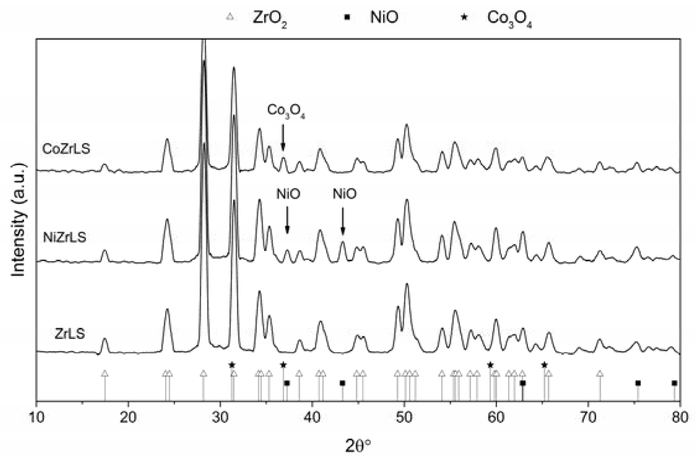
2.1. Catalyst Characterization

| Sample | Active Phase Crystal Size (nm) (by XRD) | Surface Area (m2·g−1) | Pore Volume (cm3·g−1) |
|---|---|---|---|
| ZrLS | - | 27 | 0.2 |
| NiZrLS | 28 | 14 | 0.1 |
| CoZrLS | 25 | 19 | 0.1 |

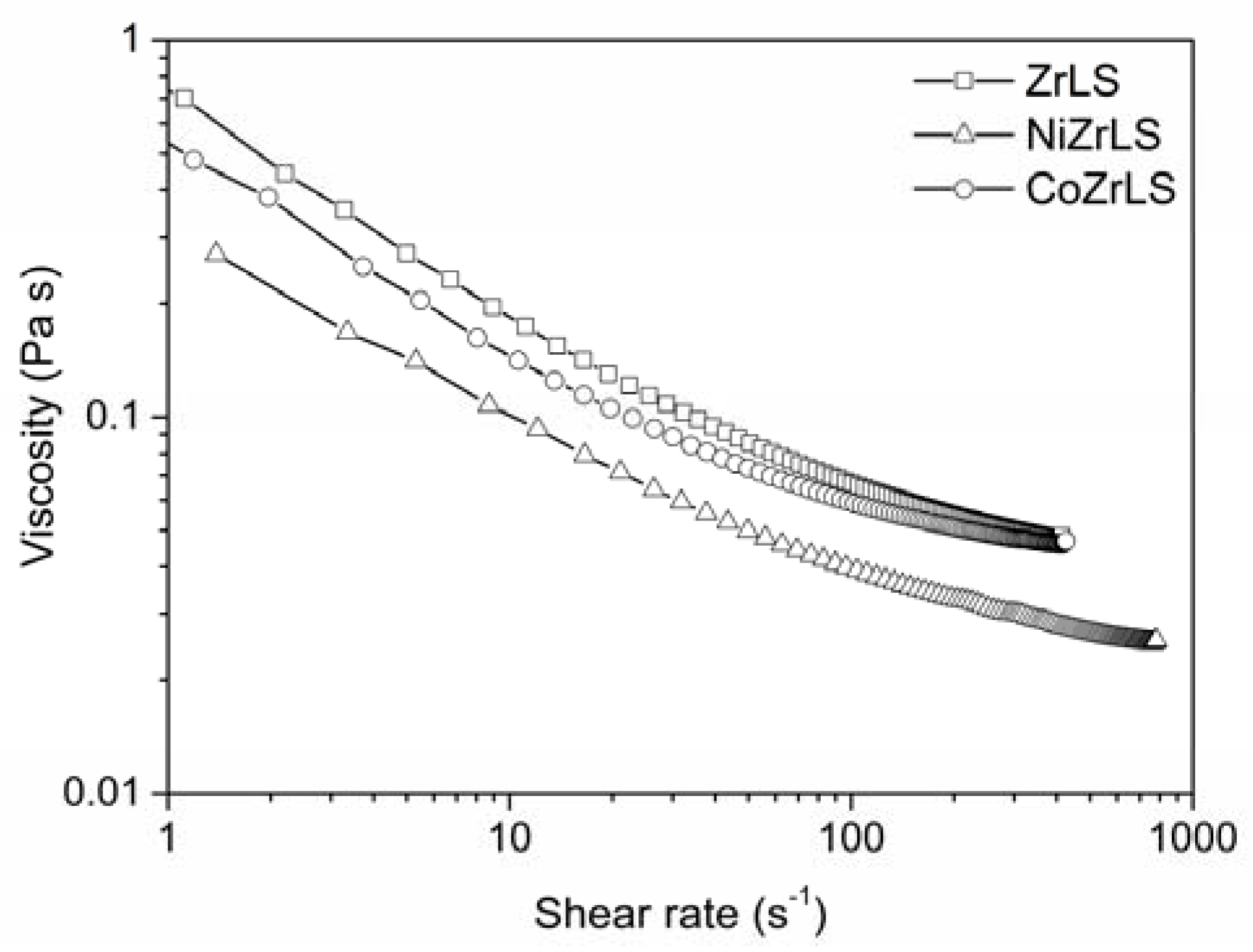
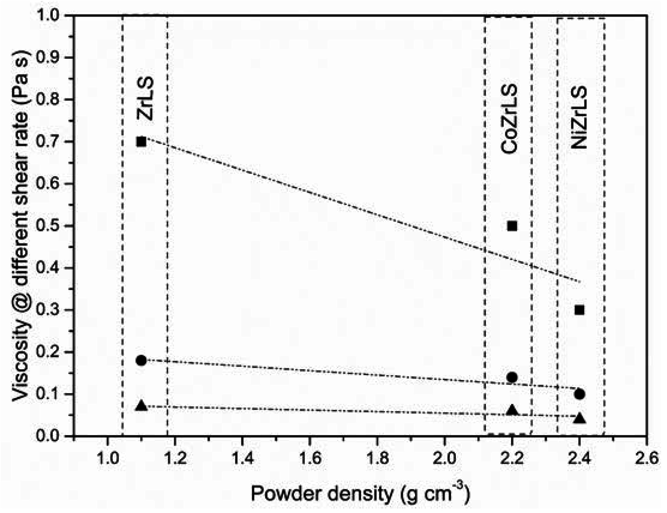
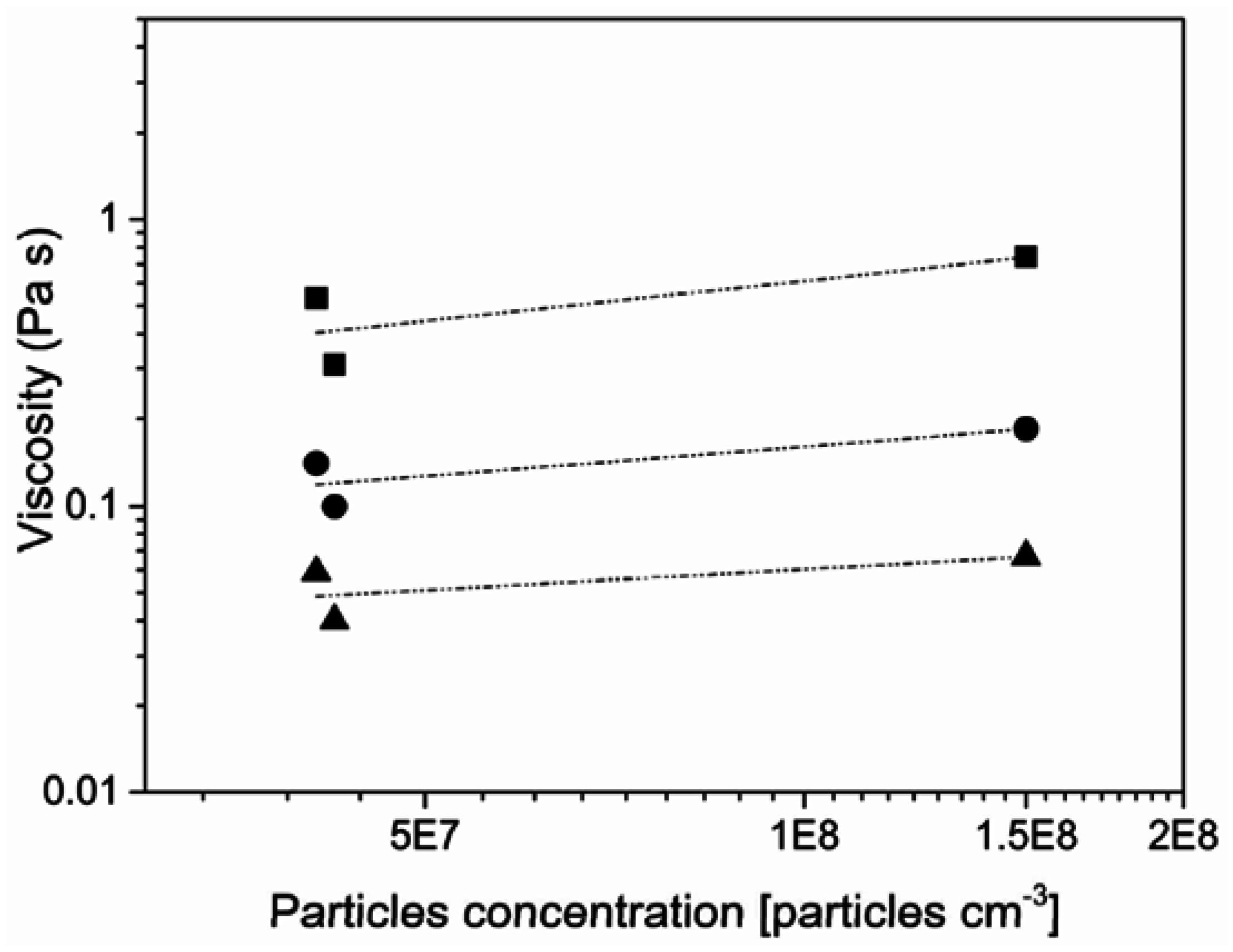
| Powder | K | Bulk Density (g·cm−3) | Real Density (g·cm−3) | Particles Concentration (Particles cm−3) | Viscosity (Pa·s) at Shear Rate: | ||
|---|---|---|---|---|---|---|---|
| 1 s−1 | 10 s−1 | 100 s−1 | |||||
| ZrLS | 1 | 5.68 | 1.13 | 1.50 × 10⁸ | 0.743 | 0.185 | 0.067 |
| NiZrLS | 0.91 | 5.77 | 2.43 | 4.24 × 10⁷ | 0.309 | 0.1 | 0.04 |
| CoZrLS | 0.76 | 5.78 | 2.16 | 4.10 × 10⁷ | 0.532 | 0.14 | 0.059 |
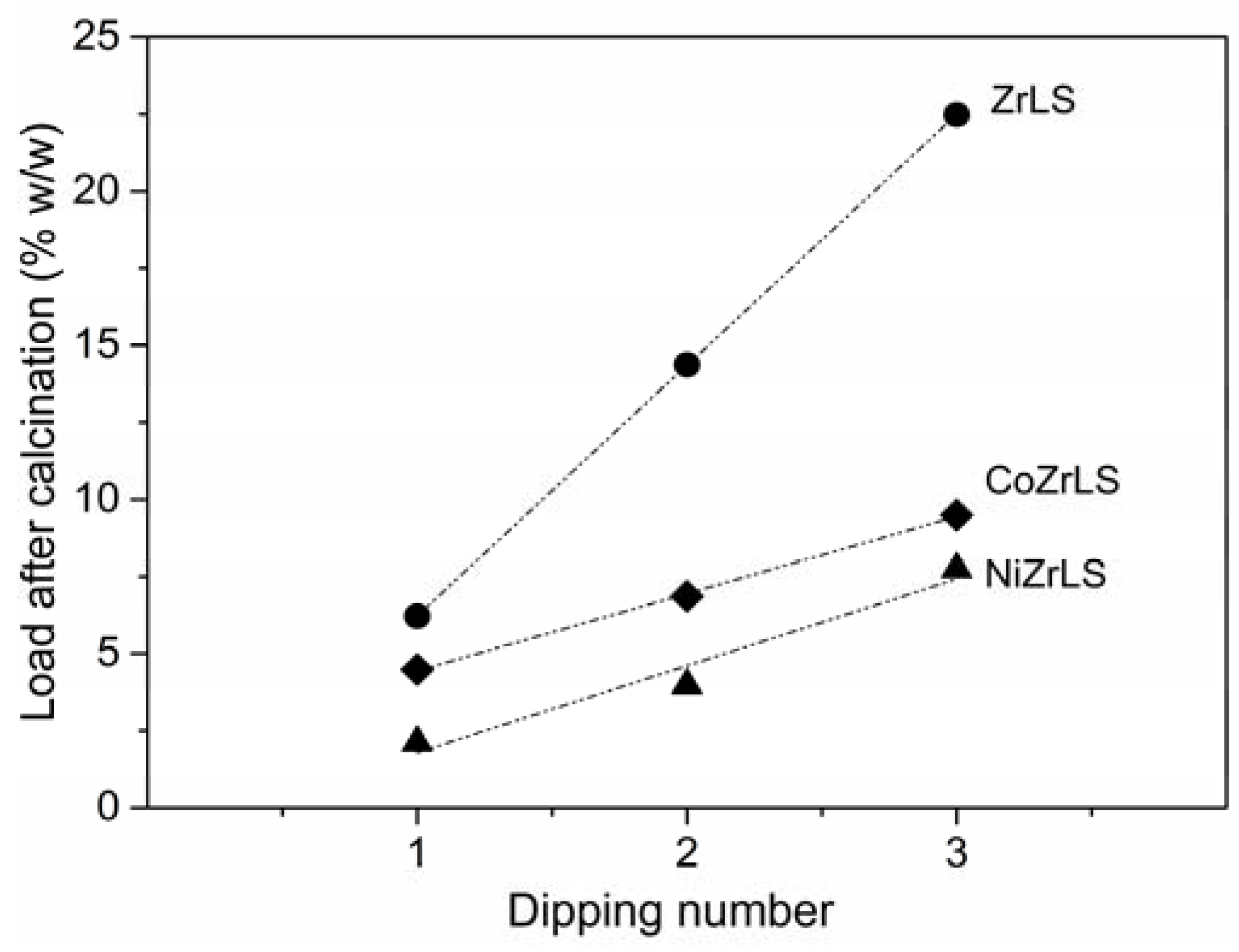
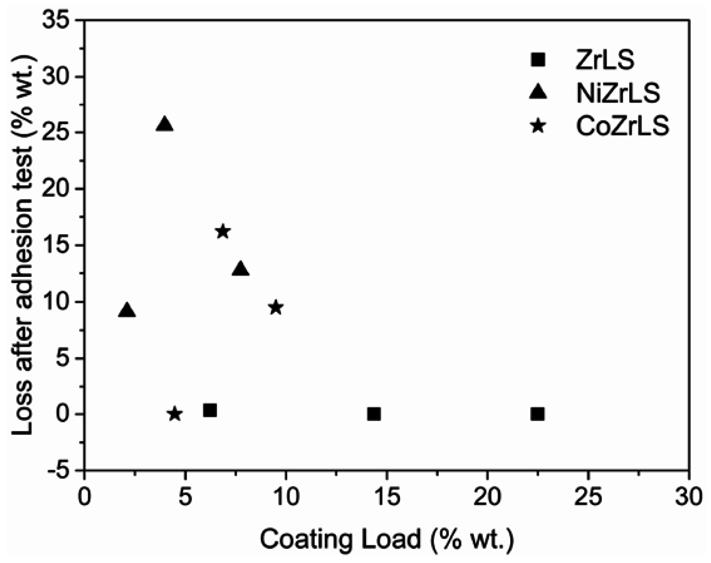
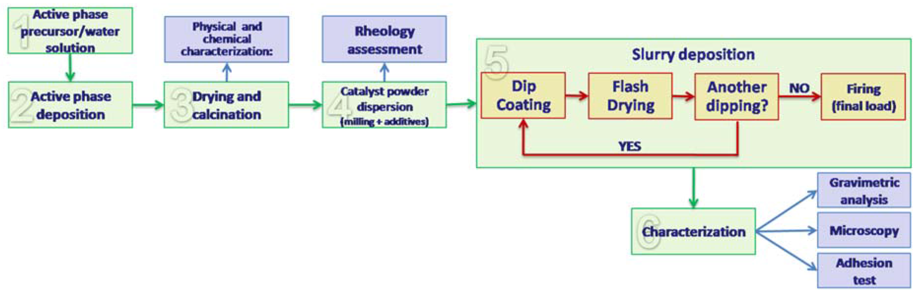
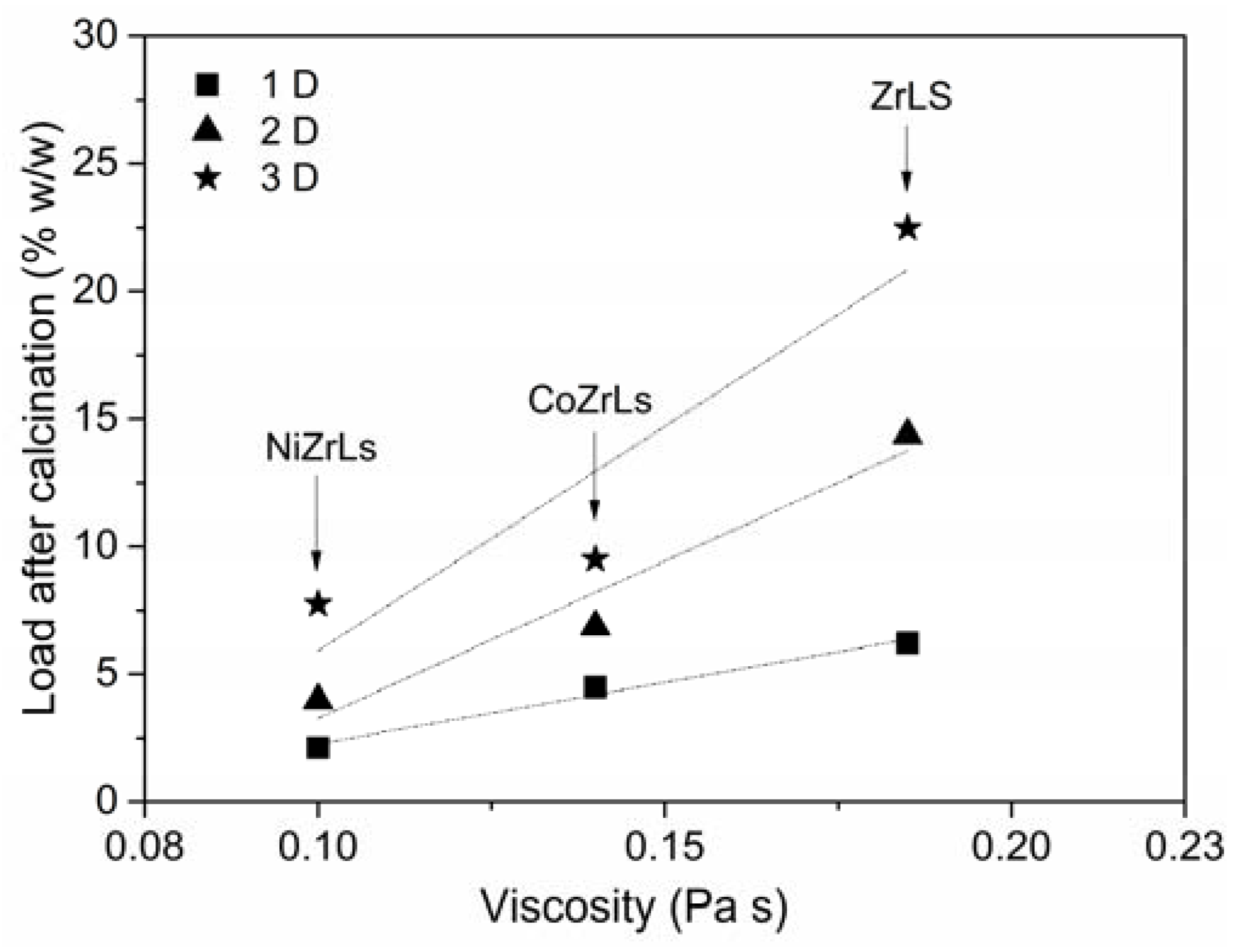
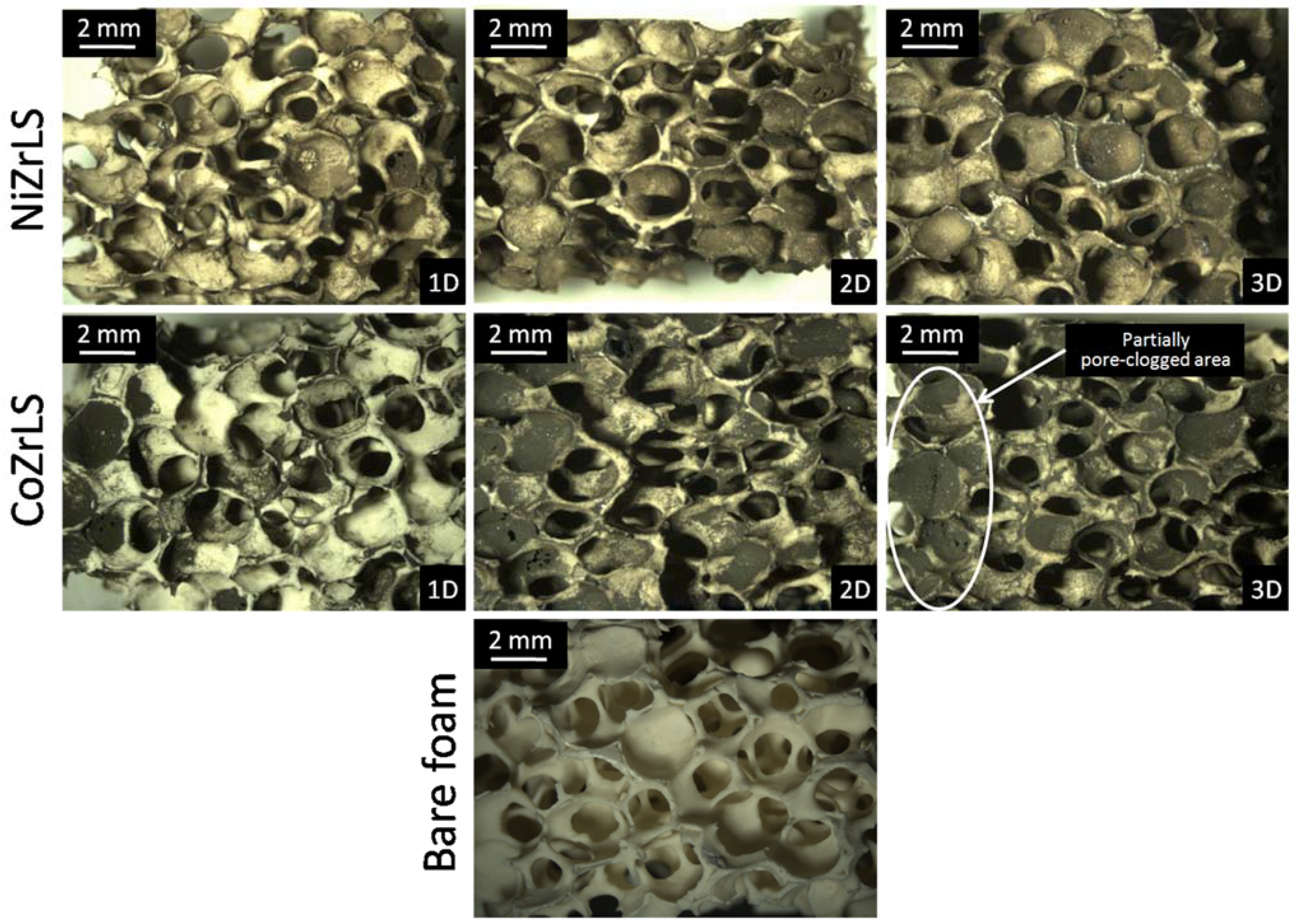
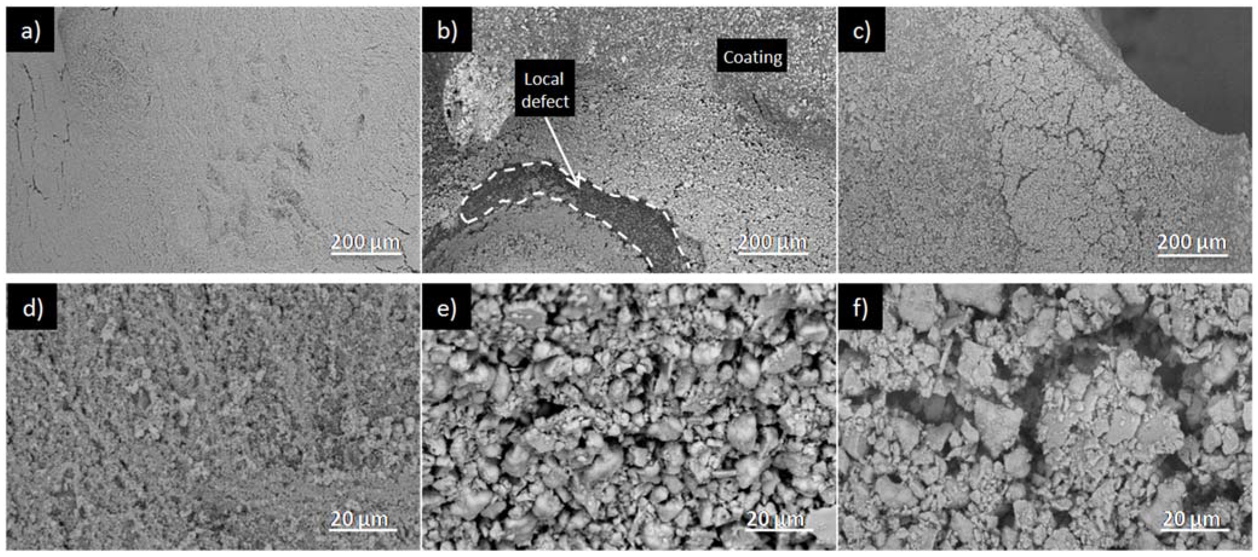
2.2. Washcoat Deposition


3. Experimental Section
3.1. Catalytic Powders Preparation and Characterization
3.2. Washcoating

4. Conclusions
Acknowledgments
Author Contributions
Conflicts of Interest
References
- Tronconi, E.; Groppi, G. Preface. Catal. Today 2009, 147, S1. [Google Scholar] [CrossRef]
- Montebelli, A.; Visconti, C.G.; Groppi, G.; Tronconi, E.; Cristiani, C.; Ferreira, C.; Kohler, S. Methods for the catalytic activation of metallic structured substrates. Catal. Sci. Tech. 2014, 4, 2846–2870. [Google Scholar] [CrossRef]
- Bagheri, S.; Muhd Julkapli, N.; Bee Abd Hamid, S. Titanium dioxide as a catalyst support in heterogeneous catalysis. Sci. World J. 2014, 2014, 727496. [Google Scholar] [CrossRef] [PubMed]
- Huirache-Acuna, R.; Nava, R.; Peza-Ledesma, C.L.; Lara-Romero, J.; Alonso-Nunez, G.; Pawelec, B.; Rivera-Munoz, E.M. SBA-15 mesoporous silica as catalytic support for hydrodesulfurization catalysts—Review. Materials 2013, 6, 4139–4167. [Google Scholar] [CrossRef]
- Trueba, M.; Trasatti, S.P. γ-Alumina as a support for catalysts: A review of fundamental aspects. Eur. J. Inorg. Chem. 2005, 17, 3393–3403. [Google Scholar] [CrossRef]
- Maciel, C.G.; Silva, T.D.; Hirooka, M.I.; Belgacem, M.N.; Assaf, J.M. Effect of nature of ceria support in CuO/CeO2 catalyst for PrOx-CO reaction. Fuel 2012, 97, 245–252. [Google Scholar] [CrossRef]
- Maupin, I.; Mijoin, J.; Barbier, J.; Bion, N.; Belin, T.; Magnoux, P. Improved oxygen storage capacity on CeO2/zeolite hybrid catalysts. Application to VOCs catalytic combustion. Catal. Today 2011, 176, 103–109. [Google Scholar] [CrossRef]
- Periyat, P.; Laffir, F.; Tofail, S.A.M.; Magner, E. A facile aqueous sol-gel method for high surface area nanocrystalline CeO2. RSC Adv. 2011, 1, 1794–1798. [Google Scholar] [CrossRef]
- Pino, L.; Vita, A.; Laganà, M.; Recupero, V. Hydrogen from biogas: Catalytic tri-reforming process with Ni/La-Ce-O mixed oxides. Appl. Catal. B 2014, 148–149, 91–105. [Google Scholar] [CrossRef]
- Iglesia, E. Design, synthesis, and use of cobalt-based Fischer-Tropsch synthesis catalysts. Appl. Catal. A 1997, 161, 59–78. [Google Scholar] [CrossRef]
- Khodakov, A.Y.; Chu, W.; Fongarland, P. Advances in the development of novel cobalt Fischer-Tropsch catalysts for synthesis of long-chain hydrocarbons and clean fuels. Chem. Rev. 2007, 107, 1692–1744. [Google Scholar] [CrossRef] [PubMed]
- Wang, C.M.; Friedrich, S.; Younkin, T.R.; Li, R.T.; Grubbs, R.H.; Bansleben, D.A.; Day, M.W. Neutral nickel(II)-based catalysts for ethylene polymerization. Organometallics 1998, 17, 3149–3151. [Google Scholar] [CrossRef]
- Li, Y.D.; Li, D.X.; Wang, G.W. Methane decomposition to COx-free hydrogen and nano-carbon material on group 8–10 base metal catalysts: A review. Catal. Today 2011, 162, 1–48. [Google Scholar] [CrossRef]
- Matsumoto, S.I. Recent advances in automobile exhaust catalysts. Catal. Today 2004, 90, 183–190. [Google Scholar] [CrossRef]
- Koltsakis, G.C.; Stamatelos, A.M. Catalytic automotive exhaust aftertreatment. Prog. Energy Combust. Sci. 1997, 23, 1–39. [Google Scholar] [CrossRef]
- Ghosh, I. Heat transfer correlation for high-porosity open-cell foam. Int. J. Heat Mass Transf. 2009, 52, 1488–1494. [Google Scholar] [CrossRef]
- Giani, L.; Groppi, G.; Tronconi, E. Mass-transfer characterization of metallic foams as supports for structured catalysts. Ind. Eng. Chem. Res. 2005, 44, 4993–5002. [Google Scholar] [CrossRef]
- Giani, L.; Groppi, G.; Tronconi, E. Heat transfer characterization of metallic foams. Ind. Eng. Chem. Res. 2005, 44, 9078–9085. [Google Scholar] [CrossRef]
- Campanati, M.; Fornasari, G.; Vaccari, A. Fundamentals in the preparation of heterogeneous catalysts. Catal. Today 2003, 77, 299–314. [Google Scholar] [CrossRef]
- Meille, V. Review on methods to deposit catalysts on structured surfaces. Appl. Catal. A 2006, 315, 1–17. [Google Scholar] [CrossRef]
- Avila, P.; Montes, M.; Miro, E.E. Monolithic reactors for environmental applications—A review on preparation technologies. Chem. Eng. J. 2005, 109, 11–36. [Google Scholar] [CrossRef]
- Brinker, C.J.; Scherer, G.W. Sol-Gel Science; Academic Press: San Diego, CA, USA, 1990. [Google Scholar]
- Middleman, S. Fundamentals of Polymers Processing; McGraw-Hill Companies: New York, NY, USA, 1977; p. 448. [Google Scholar]
- Valentini, M.; Groppi, G.; Cristiani, C.; Levi, M.; Tronconi, E.; Forzatti, P. The deposition of γ-Al2O3 layers on ceramic and metallic supports for the preparation of structured catalysts. Catal. Today 2001, 69, 307–314. [Google Scholar] [CrossRef]
- Visconti, C.G.; Tronconi, E.; Lietti, L.; Groppi, G.; Forzatti, P.; Cristiani, C.; Zennaro, R.; Rossini, S. An experimental investigation of Fischer-Tropsch synthesis over washcoated metallic structured supports. Appl. Catal. A 2009, 370, 93–101. [Google Scholar] [CrossRef]
- Cristiani, C.; Visconti, C.G.; Finocchio, E.; Stampino, P.G.; Forzatti, P. Towards the rationalization of the washcoating process conditions. Catal. Today 2009, 147, S24–S29. [Google Scholar] [CrossRef]
- Phan, X.K.; Bakhtiary-Davijany, H.; Myrstad, R.; Pfeifer, P.; Venvik, H.J.; Holmen, A. Preparation and performance of Cu-based monoliths for methanol synthesis. Appl. Catal. A 2011, 405, 1–7. [Google Scholar] [CrossRef]
- Won, J.Y.; Jun, H.K.; Jeon, M.K.; Woo, S.I. Performance of microchannel reactor combined with combustor for methanol steam reforming. Catal. Today 2006, 111, 158–163. [Google Scholar] [CrossRef]
- Germani, G.; Stefanescu, A.; Schuurman, Y.; van Veen, A.C. Preparation and characterization of porous alumina-based catalyst coatings in microchannels. Chem. Eng. Sci. 2007, 62, 5084–5091. [Google Scholar] [CrossRef]
- Lin, K.S.; Pan, C.Y.; Chowdhury, S.; Lu, W.; Yeh, C.T. Synthesis and characterization of CuO/ZnO-Al2O3 catalyst washcoat thin films with ZrO2 sols for steam reforming of methanol in a microreactor. Thin Solid Films 2011, 519, 4681–4686. [Google Scholar] [CrossRef]
- Barth, N.; Zimmermann, M.; Becker, A.E.; Graumann, T.; Garnweitner, G.; Kwade, A. Influence of TiO2 nanoparticle synthesis on the properties of thin coatings. Thin Solid Films 2015, 574, 20–27. [Google Scholar] [CrossRef]
- Truyen, D.; Courty, M.; Alphonse, P.; Ansart, F. Catalytic coatings on stainless steel prepared by sol-gel route. Thin Solid Films 2006, 495, 257–261. [Google Scholar] [CrossRef]
- Agrafiotis, C.; Tsetsekou, A.; Leon, I. Effect of slurry rheological properties on the coating of ceramic honeycombs with yttria-stabilized-zirconia washcoats. J. Am. Ceram. Soc. 2000, 83, 1033–1038. [Google Scholar] [CrossRef]
- Cristiani, C.; Finocchio, E.; Latorrata, S.; Visconti, C.G.; Bianchi, E.; Tronconi, E.; Groppi, G.; Pollesel, P. Activation of metallic open-cell foams via washcoat deposition of Ni/MgAl2O4 catalysts for steam reforming reaction. Catal. Today 2012, 197, 256–264. [Google Scholar] [CrossRef]
- Olhero, S.M.; Ferreira, J.M.F. Influence of particle size distribution on rheology and particle packing of silica-based suspensions. Powder Technol. 2004, 139, 69–75. [Google Scholar] [CrossRef]
- Zupancic, A.; Lapasin, R.; Kristoffersson, A. Influence of particle concentration on rheological properties of aqueous α-Al2O3 suspensions. J. Eur. Ceram. Soc. 1998, 18, 467–477. [Google Scholar] [CrossRef]
- Agrafiotis, C.; Tsetsekou, A. The effect of processing parameters on the properties of γ-alumina washcoats deposited on ceramic honeycombs. J Mater. Sci. 2000, 35, 951–960. [Google Scholar] [CrossRef]
- Balzarotti, R.; Cristiani, C.; Latorrata, S.; Migliavacca, A. Washcoating of low surface area cerium oxide on complex geometry substrates. Part. Sci. Technol. 2015, in press. [Google Scholar] [CrossRef]
- Sutton, D.; Kelleher, B.; Ross, J.R.H. Review of literature on catalysts for biomass gasification. Fuel Process. Technol. 2001, 73, 155–173. [Google Scholar] [CrossRef]
- Cullity, B.D.; Stock, S.R. Elements of X-ray Diffraction, 3rd ed.; Prentice Hall: Upper Saddle River, NJ, USA, 2001. [Google Scholar]
© 2015 by the authors; licensee MDPI, Basel, Switzerland. This article is an open access article distributed under the terms and conditions of the Creative Commons Attribution license (http://creativecommons.org/licenses/by/4.0/).
Share and Cite
Balzarotti, R.; Ciurlia, M.; Cristiani, C.; Paparella, F. Washcoat Deposition of Ni- and Co-ZrO2 Low Surface Area Powders onto Ceramic Open-Cell Foams: Influence of Slurry Formulation and Rheology. Catalysts 2015, 5, 2271-2286. https://doi.org/10.3390/catal5042271
Balzarotti R, Ciurlia M, Cristiani C, Paparella F. Washcoat Deposition of Ni- and Co-ZrO2 Low Surface Area Powders onto Ceramic Open-Cell Foams: Influence of Slurry Formulation and Rheology. Catalysts. 2015; 5(4):2271-2286. https://doi.org/10.3390/catal5042271
Chicago/Turabian StyleBalzarotti, Riccardo, Mirko Ciurlia, Cinzia Cristiani, and Fabio Paparella. 2015. "Washcoat Deposition of Ni- and Co-ZrO2 Low Surface Area Powders onto Ceramic Open-Cell Foams: Influence of Slurry Formulation and Rheology" Catalysts 5, no. 4: 2271-2286. https://doi.org/10.3390/catal5042271
APA StyleBalzarotti, R., Ciurlia, M., Cristiani, C., & Paparella, F. (2015). Washcoat Deposition of Ni- and Co-ZrO2 Low Surface Area Powders onto Ceramic Open-Cell Foams: Influence of Slurry Formulation and Rheology. Catalysts, 5(4), 2271-2286. https://doi.org/10.3390/catal5042271