Article

Controllable Synthesis of Ultrafine Ag NPs/Functionalized Graphene-Introduced TiO2 Mesoporous Hollow Nanofibers by Coaxial Electrospinning for Photocatalytic Oxidation of CO

Key Laboratory of Functional Inorganic Materials Chemistry (Ministry of Education), School of Chemistry and Materials Science, International Joint Research Center for Catalytic Technology, Heilongjiang University, Harbin 150080, China
*
Authors to whom correspondence should be addressed.
Catalysts 2025, 15(3), 231; https://doi.org/10.3390/catal15030231
Submission received: 20 January 2025 / Revised: 21 February 2025 / Accepted: 26 February 2025 / Published: 27 February 2025
(This article belongs to the Special Issue TiO2 Photocatalysts: Design, Optimization and Application)

Abstract

:
Solar-driven catalytic oxidation processes for the removal of toxic gaseous pollutants have attracted considerable scientific attention, and there is a strong desire to improve the mass transfer, photogenerated charge separation, and O2 activation by regulating the structure of the photocatalyst. Initially, functionalized graphene–TiO2 mesoporous hollow nanofibers have been controllably fabricated by a coaxial electrospinning technique, in which functionalized graphene is controllably prepared through a sequential diazonium functionalization and silane modification and ensures its uniform distribution among TiO2 nanoparticles (NPs). Subsequently, the ultrafine Ag NPs are primarily anchored onto the surface of graphene by an in situ frozen photodeposition strategy, producing Ag/functionalized graphene–TiO2 mesoporous hollow nanofibers (Ag/SiG-TO MPHNFs). The optimal Ag/SiG-TO MPHNFs exhibit 3.9-fold and 4.6-fold enhancements in CO photooxidation compared with TO MPHNFs and P25 TiO2, respectively. The enhanced photoactivity can be attributed to three factors: the creation of the mesoporous hollow structure accelerates mass transfer, the incorporation of graphene facilitates the transfer of photogenerated electrons from TiO2 to graphene, and the anchoring of Ag NPs improves O2 activation.

Graphical Abstract

1. Introduction

CO, a hazardous atmospheric contaminant, predominantly originates from anthropogenic sources, including vehicular exhaust, industrial emissions, and incomplete hydrocarbon combustion processes. Despite its acute and chronic toxicity to human physiological systems, CO’s insidious nature—characterized by undetectable sensory cues—frequently leads to an underestimation of the exposure risks [1,2]. Conventional abatement strategies such as physical adsorption technology demonstrate limited CO removal efficiency, while thermal catalytic approaches face practical constraints due to excessive energy demands and poor performance in low-concentration environments [3,4]. These limitations have stimulated significant interest in developing sustainable catalytic technology capable of ambient-condition CO oxidation. Photocatalytic conversion utilizing O2 as the oxidant presents particular promise, enabling efficient CO-to-CO2 transformation under mild operational conditions [5,6,7]. Within this technological landscape, TiO2 has attracted substantial attention as a benchmark photocatalyst, distinguished by its exceptional photooxidative performance, economic feasibility, and minimal environmental footprint, positioning it as a pivotal material for next-generation air purification applications [8,9,10]. Kolobov et al. (2017) focused on CO oxidation by noble metal/TiO2 photocatalysts, exploring the impacts of noble metal properties, content, and preparation methods on the photocatalytic rate, mainly via the nanoparticle size and charge state [11]. However, conventional TiO2 structures (such as nanoparticles and nanosheets) often suffer from agglomeration, inefficient photogenerated charge separation, and reduced catalytic site exposure, which compromise their photocatalytic performance. The regulation of TiO2 structure based on the electrospinning technique is one of the effective and promising methods to enhance its photocatalytic performance.
Currently, the hot topics in electrospinning technology revolve around the regulation of spatial structure and the design of heterojunction structures, which play a crucial role in enhancing photocatalytic performance [12,13]. Jiang et al. (2022) designed a sandwich-like substructure plasmonic heterostructure by embedding Au NPs into TiO2 electrospun nanofibers by assembling W18O49 nanowires on the outer surface for photocatalytic CO2 reduction [14]. However, its low specific surface area limits mass transfer and reactant adsorption, which are critical factors in the reaction involving gas molecules. Typically, porous and hollow structures are incorporated into photocatalysts to increase the surface area and improve mass transfer, among other benefits. Our previous studies have demonstrated the successful fabrication of TiO2 mesoporous hollow nanofibers (MPHNFs) using coaxial electrospinning combined with polyetherimide (PEI) regulation. In this process, PEI serves as an effective porogen while simultaneously improving the phase stability of TiO2 and pore stability within the nanofibers [15]. The creation of this mesoporous hollow structure facilitates better mass transportation, leading to improved photocatalytic performance. While the regulation of spatial structure has proven beneficial for enhancing mass transfer and photocatalytic performance, it often overlooks the effective connection between particles within the basic unit and the regulation of charge-directed transport. Therefore, it is necessary to introduce flexible electron- or hole-regulating materials between the particles in the fiber wall to form heterojunctions with the matrix, improving charge separation.
From this perspective, graphene derivatives emerge as ideal charge mediators for photocatalytic systems due to their excellent charge mobility (15,000 cm2 V−1 s−1) and mechanical resilience [16]. Among them, GO or rGO exhibit certain advantages and are, thus, used in surface loading and catalysis. This is attributed to their abundant surface oxygen functional groups and defects, which are used for constructing efficient photocatalysts [17,18]. However, the conventional electrospinning techniques require high-temperature processing (typically 500 °C) to crystallize metal oxide components, posing significant challenges for GO/rGO integration, given their limited thermal stability (<500 °C). For instance, Kang et al. (2022) developed in situ growth rGO-wrapped Ag/TiO2 nanofibers via coaxial electrospinning [19]. However, the inherent low thermal stability of rGO necessitated this encapsulation strategy, which consequently introduced critical limitations, such as insufficient accessible catalytic sites and poor photogenerated charge separation efficiency. Comparatively, graphene offers more advantages in terms of conductivity and thermal stability due to its high graphitization [20]. Unfortunately, the absence of functional groups and defects on the graphene surface poses a significant challenge to achieving homogeneous dispersion in liquid-phase systems [21]. Previous studies have shown that pristine graphene can be functionalized with p-aminobenzoic acid using the diazonium-grafting method, allowing the basal planes to be extended by benzoic acid groups [22,23]. This approach enables the homogeneous dispersion of graphene in water while preserving its intact structure and excellent conductivity. Therefore, diazonium functionalization shows potential for achieving a homogeneous dispersion of graphene within electrospinning solutions, ultimately improving the uniformity of the resultant composite. However, this functionalization is susceptible to disruption during subsequent calcination processes, leading to diminished interaction between graphene and TiO2. Our previous research has demonstrated that incorporating silane coupling agents into the composite precursor facilitates the formation of high-temperature-resistant Si-O bonds among the composites, thereby reinforcing their interfacial adhesion [24,25]. Thus, the sequential use of diazonium functionalization and silane modification achieves uniform dispersion of graphene while constructing an effective and robust interface between graphene and TiO2.
O2 is a key reactant in oxidation reactions. However, its ground state is highly stable, making it challenging to directly engage in chemical reactions. Pan et al. (2022) developed a sub-nano CuO/graphdiyne catalyst for CO oxidation [26]. Adjacent C sp-hybridized and Cu sites at nanocluster interfaces are key for effective O2 activation via bridge adsorption of O2. Therefore, effective O2 activation is crucial for enhancing the TiO2 photocatalytic CO oxidation performance [27,28]. Current studies have revealed that modifying TiO2 with plasmonic metals such as Ag or Cu is a common and effective strategy [29,30]. However, the traditional impregnation and calcination methods often result in random deposition, easy aggregation, and oxidation of the metal nanocrystal, leading to unsatisfactory catalytic performance [31]. In contrast, the photodeposition method can effectively induce the selective deposition of metal ions on the electron-rich region, which favors the catalysis of the reduction reaction. Nevertheless, its weak controllability may lead to the formation of large particle sizes, thereby impeding the effective utilization of plasma metals [32]. To address this, our research group has developed the frozen photodeposition strategy, which can regulate metal ion deposition from a kinetic perspective. This strategy achieves an efficient and uniform deposition of ultrafine particles, thereby exhibiting superior photocatalytic performance [33]. Based on this advancement, it is anticipated that the assistive effect of Ag on the surface catalytic performance of TiO2 can be significantly improved through this innovative strategy.
This study demonstrates the successful and controllable preparation of ultrafine Ag NPs loaded onto functionalized graphene–TiO2 mesoporous hollow nanofibers (denoted as Ag/SiG-TO MPHNFs) through a two-step synthetic method for the photo-oxidation of CO to CO2. Initially, functionalized graphene–TiO2 MPHNFs are controllably fabricated using the coaxial electrospinning technique, in which functionalized graphene is controllably prepared via a sequential process that encompasses diazonium functionalization and silane modification and ensures its uniform distribution among TiO2 NPs. The diazonium functionalization successfully grafts polar moieties onto the graphene surface, facilitating its homogeneous dispersion within liquid media while preserving its structure and electrical conductivity. The silane modification ensures the establishment of a stable, high-temperature-resistant interface linkage between the graphene and TiO2. Subsequently, the ultrafine Ag NPs are primarily anchored onto the surface of graphene by a light-induced in situ deposition strategy under a frozen environment created by liquid N2. Experimental results reveal that the enhanced photoactivity is mainly attributed to (1) the creation of the mesoporous hollow structure, which accelerates mass transfer; (2) the incorporation of graphene, which facilitates the transfer of photogenerated electrons from TiO2 to graphene; and (3) the precise anchoring of Ag NPs, which captures electrons in graphene and promotes preferential O2 activation. Consequently, the optimal Ag/SiG-TO MPHNFs exhibit 3.9-fold and 4.6-fold higher CO conversion rates compared to those of TO MPHNFs and P25 TiO2, respectively. This work provides a unique idea for designing and producing highly active TiO2-based mesoporous hollow photocatalytic materials.

2. Results and Discussion

2.1. Design and Synthetic Pathway

The design and synthetic pathway of Ag/SiG-TO MPHNFs is illustrated in Scheme 1. Initially, to achieve a uniform and stable dispersion of graphene nanosheets (GR) within the electrospinning solution composed of polyethyleneimine (PEI) and tetrabutyl titanate (TBT) micelles, surface functionalization is performed. As shown in Figure S1, benzoic acid groups are successfully grafted onto the GR surface via diazonium functionalization using p-amino-benzoic acid, while preserving the morphology and graphitization of GR. This reaction process is shown in Scheme S1. Subsequently, Si species are introduced through further modification with KH550, which is shown as Scheme S2. Comparative experiments assessing dispersion stability demonstrate that pristine GR struggles to attain stable dispersion within electrospinning solutions (Figure S2). In contrast, GR that has undergone diazonium functionalization for grafting benzoic acid (the sample is named BGR) exhibits uniform and stable dispersion, and subsequent modification with KH550 does not compromise this stability. However, GR modified solely with KH550 without prior diazonium functionalization fails to achieve stable dispersion, potentially due to the scarcity of functional groups on the GR surface, impeding the direct attachment of KH550. In conclusion, diazonium functionalization is crucial for achieving a uniform and stable dispersion of GR. Moving forward, the formulated electrospinning solution is used as the shell precursor, with paraffin oil serving as the core precursor (Scheme S3). Nanofibers are then synthesized via the coaxial electrospinning technique and subsequently subjected to a calcination process to yield a hollow fiber structure. Lastly, ultrafine Ag NPs are deposited in situ on the surfaces of nanofibers using a frozen photodeposition strategy, thereby forming the Ag/SiG-TO MPHNFs heterojunction. For comparison, GO and rGO, instead of KH550-BGR, have been utilized to prepare GO-TO MPHNFs and rGO-TO MPHNFs through the same process, respectively. As illustrated in Figure S3, comparisons of photographic images before and after the calcination of the samples, along with a DRS analysis of the calcined samples, reveal that GR possesses superior thermal stability and remains stable within the composite structure.

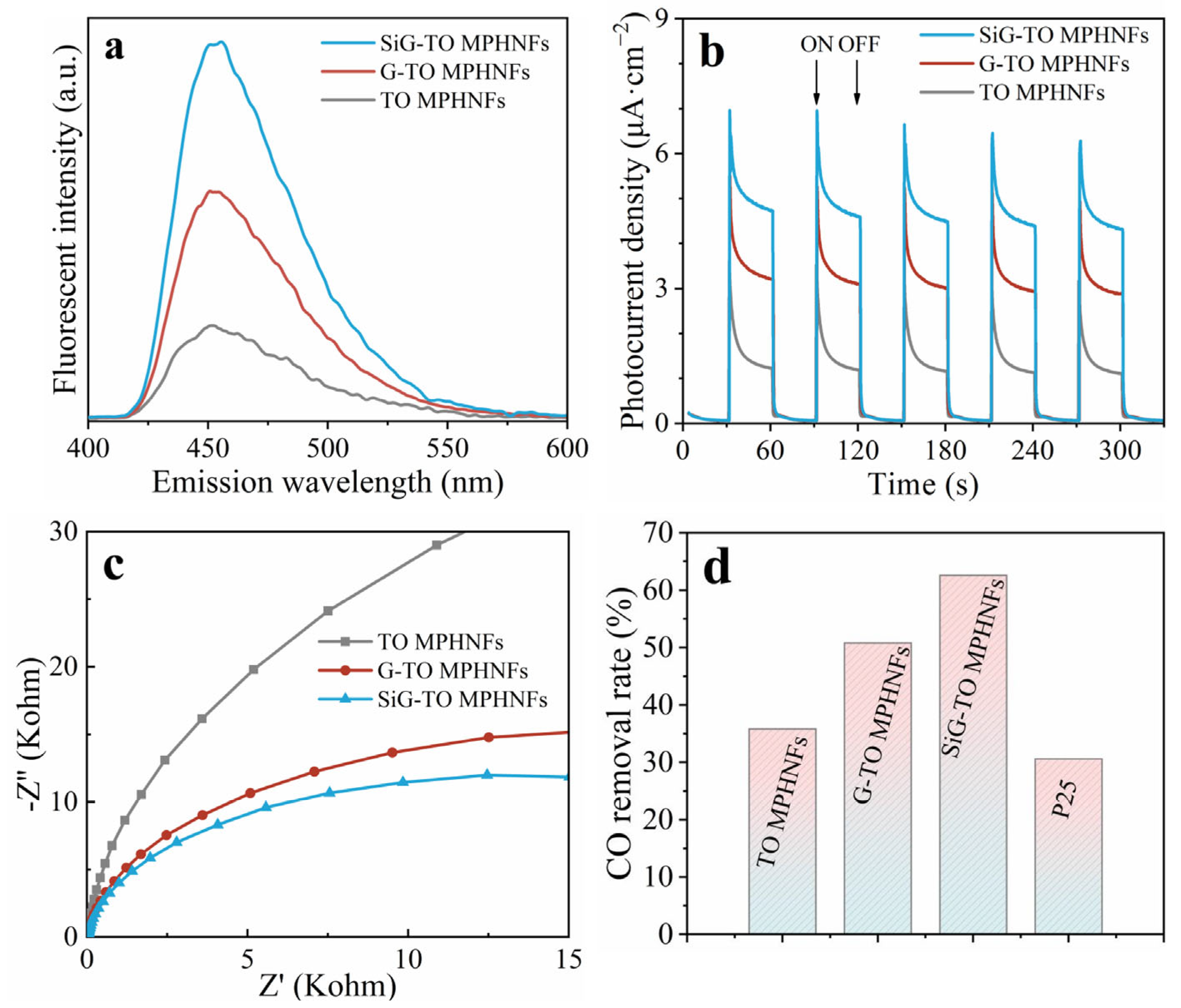
2.2. Functionalized Graphene–TiO2 Mesoporous Hollow Nanofibers

Initially, the samples are optimized by adjusting the mass ratio between the GR and TiO2, which is represented as xG-TO MPHNFs (x = 0.5, 1, 1.5, and 2) As depicted in Figure S4 and Table S1, as the mass ratio increases, minimal changes are discernible in both the crystallinity and specific surface area of the samples, and the introduction of GR has no significant effect on pore size. The enhancement in visible-light absorption is attributed to the intrinsic absorption properties of GR. Based on the results derived from steady-state surface photovoltage spectroscopy (SS-SPS) and fluorescence (FS) spectra, which are related to the formed hydroxyl radical (·OH) amounts, the incorporation of an optimal amount of GR is found to be beneficial for accelerating photogenerated charge separation. Consequently, the 1.5G-TO MPHNFs (hereinafter referred to as G-TO MPHNFs) exhibit the best photogenerated charge separation and photocatalytic CO oxidation performance (where the 1.5 was determined by the mass ratio percentage of TiO2 to BGR). Furthermore, the BGR is replaced with the equivalent KH550-functionalized BGR, and the impact of introducing KH550 into the G-TO MPHNFs has been explored. Notably, successful modification with KH550 preserves the nanosheet structure and graphitization degree of BGR (Figure S5), while exerting negligible influence on the crystallinity, light absorption, pore structure, and specific surface area of the samples (Figure S6a–c and Table S2). Similarly, the introduction of an appropriate amount of KH550 effectively enhances the photogenerated charge separation and photocatalytic performance of the samples, with the 6SiG-TO MPHNFs (where the 6 was determined by the mass ratio of KH550 to BGR in modifying) demonstrating the best photocatalytic performance (Figure S6d–f). Therefore, the 6SiG-TO MPHNFs have been selected as the test sample and labeled as SiG-TO MPHNFs for subsequent experiments.
Furthermore, a comparative analysis of a series of samples is conducted, as shown in Figure 1a and Figure S7. Both the G-TO and SiG-TO MPHNFs exhibit a relatively uniform hollow structure, with a diameter of approximately 400 nm and a wall thickness of about 80 nm, which are smaller than those of the TO MPHNFs. The HRTEM image reveals that the G-TO and SiG-TO MPHNFs are composed of TiO2 NPs stacked along the fibers, consistent with the structure of TO MPHNFs. Conspicuous lattice fringes with a d-spacing of 0.35 nm can be observed in the HRTEM image, corresponding to the (101) plane of anatase TiO2 (Figure 1b and Figure S7). Meanwhile, the specific surface areas and pore structures of the samples are analyzed by N2 adsorption–desorption (Figure 1c). All samples exhibit the typical characteristics of type IV isotherms with an H2 hysteresis loop, indicating the presence of a significant number of mesopores on the nanofiber walls (Figure S8a). The specific surface areas of the SiG-TO MPHNFs (49.5 m2 g−1) are larger than those of the G-TO MPHNFs (40.9 m2 g−1) and TO MPHNFs (42.3 m2 g−1). In conjunction with the XRD results, it is revealed that the modification of graphene with KH550 facilitates the attainment of a larger specific surface area in the product by inhibiting the growth of TiO2 NPs [34], with negligible impact on the crystalline and mesoporous structure of the product (Figure S8b).
To further verify the effective combination of graphene and TiO2, and the role of Si introduction in the composite, X-ray photoelectron spectroscopy (XPS) characterization was performed on the samples. As shown in Figure S9a, the full spectrum indicates the presence of Ti, O, and C in all samples, with Si originating from KH550, which is only observed in the SiG-TO MPHNFs. A notable red shift was observed in the high-resolution Ti 2p and O 1s (Figure 1d and Figure S9b) binding energies of SiG-TO and G-TO MPHNFs compared to the TO MPHNFs. This is attributed to lattice distortions resulting from the interaction between Ti and C atoms [35], given that the electronegativity of C atoms is lower than that of O atoms. Additionally, the C 1s spectra of all samples reveal typical peaks at 284.8 eV, 286.0 eV, and 288.6 eV corresponding to C-C, C-O, and O-C=O bonds, respectively (Figure 1e). Remarkably, the emergence of a new peak at 283.6 eV in G-TO MPHNFs suggests C-Ti-O bonding at the interfaces of graphene–TiO2 heterojunctions, demonstrating intimate interfacial interactions between graphene and TiO2 [36,37]. When KH550 was introduced onto graphene during the preparation of SiG-TO MPHNFs, peaks at 101.6 eV and 103.5 eV were ascribed to C-Si-O and Si-O, respectively (Figure 1f) [38]. Furthermore, the proportion of the peak at 283.6 eV shows a significant increase which is ascribed to C-Si-O by KH550 introduction [39]. This indicates intimate interfacial interactions between Si-O and TiO2. Based on these data, it is evident that the introduction of functionalized GR achieves effective binding with TiO2 without significantly altering the original mesoporous and hollow nanofiber structure. Moreover, modifying BGR with KH550 could control particle growth, leading to larger specific surface areas and further enhancing the interface connection between graphene and TiO2.
Building upon the structural advantages of the mesoporous nanofibers and the intercalated graphene mentioned earlier, we further investigate the charge separation of the catalyst. Evaluating the photogenerated charge separation is an effective approach, which involves assessing the FS spectra related to the formed ·OH radicals, photocurrent response density measurements, and electrochemical impedance spectroscopy (EIS). As shown in Figure 2a, the FS signal intensity of G-TO and SiG-TO MPHNFs is significantly enhanced compared to TO MPHNFs, with SiG-TO MPHNFs exhibiting the highest intensity. Furthermore, the photocurrent is determined largely by the separation efficiency of the photogenerated electron–hole pairs within the photocatalyst. The higher photocurrent of SiG-TO MPHNFs indicates that the separation efficiency of photoinduced electrons and holes can be improved through the electronic interaction between SiG and TiO2 (Figure 2b). These results are further corroborated by the SS-SPS (Figure S10). In the EIS test, the arc radius on the EIS spectra indicates the resistance of the material. The smaller semicircle size reflects an effective separation of photogenerated electron–hole pairs and a fast interfacial charge transfer to the electron donor or acceptor. The SiG-TO MPHNFs display the smallest semicircle radius, indicating the lowest resistance among the samples and, consequently, the fastest interfacial charge carrier transfer (Figure 2c). The aforementioned results clearly demonstrate that the introduction of GR significantly improves the charge transfer and separation in TO, with the modification using KH550 further amplifying this enhancement. This is primarily attributed to the synergistic effect of graphene’s exceptional electrical conductivity and the Si-O bridging, both of which facilitate the interfacial photogenerated charge transfer and separation. Based on this analysis, we speculate that the SiG-TO MPHNFs exhibit excellent photocatalytic CO oxidation performance. When compared with commercial P25, TO, and G-TO MPHNFs (Figure 2d), the prepared SiG-TO MPHNFs display the highest CO oxidation conversion, which aligns with the results of the charge separation analysis.
To further affirm the impact of the interaction between graphene and TiO2 nanofibers in the composite, a control sample prepared through a wet chemical method was named SiG/TO MPHNFs. When compared to SiG-TO MPHNFs, which feature the in situ dispersion of graphene within the TiO2 fiber walls, the SiG/TO MPHNFs exhibit enhanced optical absorption but a decreased photocatalytic CO oxidation capacity (Figure S11). This observation underscores that the strategy of embedding graphene directly within the TiO2 fiber walls is advantageous for boosting photocatalytic activity. The diminished performance of SiG/TO MPHNFs can be attributed to the SiG modification on the nanofiber surface, which reduces light absorption and weakens the enhancement effect of charge separation within the TiO2 fibers. Thus, the positioning of graphene within the interior of the fiber walls emerges as a crucial factor contributing to the exceptional photocatalytic activity of SiG-TO MPHNFs.

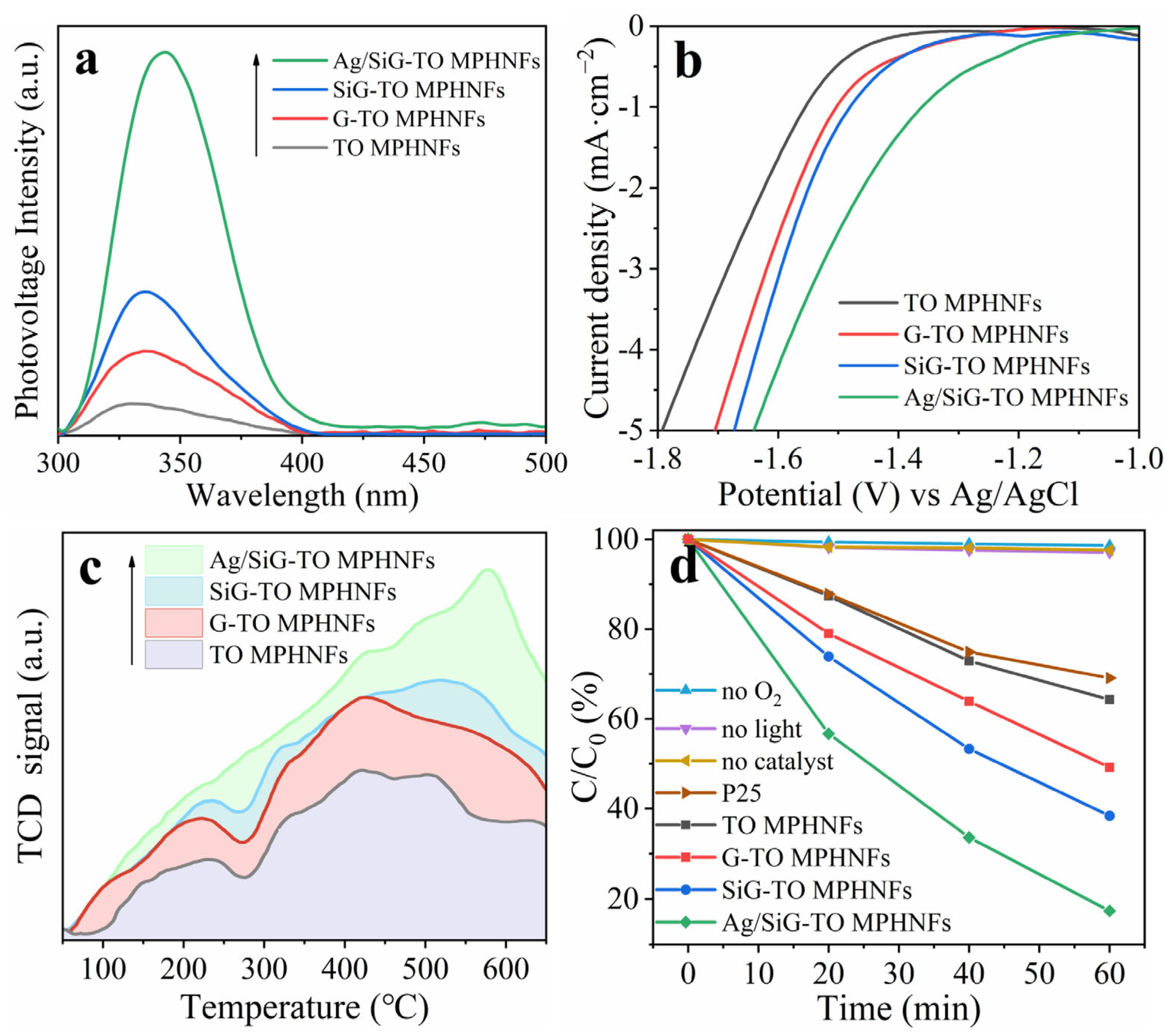
2.3. Ultrafine Ag NPs Modified SiG-TO MPHNFs

The ultrafine Ag NPs are deposited onto the optimal sample, SiG-TO MPHNFs, using a frozen photodeposition strategy. SiG-TO MPHNFs with ultrafine Ag NPs added are referred to as xAg/SiG-TO MPHNFs, where x signifies the mass ratio percentage of SiG-TO MPHNFs to Ag. As illustrated in Figure 3a and Figure S12a, the incorporation of Ag NPs does not alter the spatial configuration or crystal structure of SiG-TO MPHNFs. Furthermore, the HRTEM image (Figure 3b) of a selected area of Ag/SiG-TO MPHNFs confirms the deposition of Ag NPs with a size below 2 nm onto the fibers, along with lattice fringes corresponding to the (111) plane of Ag NPs. The energy-dispersive X-ray (EDX) elemental-mapping images (Figure 3c) reveal that Ag is relatively uniformly distributed on the fiber surface, with localized regions of higher aggregation density. This may be attributed to the exposure of graphene, leading to localized enrichment of photo-generated electrons during the deposition of Ag. Additionally, the Ag 4D XPS spectra (Figure 3d) verify the metallic nature of the incorporated Ag, which is consistent with the results obtained from DRS (Figure S12b) [40]. Specifically, Ag NPs exhibit a pronounced plasmonic resonance absorption that intensifies with an increasing Ag content. Notably, the introduction of Ag has a negligible impact on the pore structure of the fibers (Figure S12c and Table S3). Based on the above analysis, ultrafine Ag NPs have been successfully modified onto the fibers, predominantly on the graphene surface.
We focus on investigating the impact of Ag incorporation on the photogenerated charge separation and O2 activation capacity of the SiG-TO MPHNFs. Initially, samples with varying Ag loadings are characterized using SS-SPS. Generally, a higher SS-SPS signal indicates superior charge separation and enhanced efficiency in the capture of photogenerated electrons by O2. It is evident that Ag/SiG-TO MPHNFs exhibit higher SPS signals, with the optimal performance observed in the 1.5% Ag-loaded sample (denoted as Ag/SiG-TO MPHNFs) (Figure 4a and Figure S13). Following this, electrochemical measurements are conducted to assess the catalytic function of Ag NPs. Figure 4b displays the electrochemical reduction curves of the samples in an O2-saturated electrolyte, where Ag/SiG-TO MPHNFs show the lowest onset overpotential, suggesting that Ag decoration improves O2 reduction. These results clearly demonstrate that the decorated Ag NPs effectively capture electrons from graphene and facilitate O2 reduction. The adsorption of O2 reactant at active sites is crucial for the O2 activation. Therefore, we investigated the interactions between the photocatalysts and O2 using O2 temperature-programmed desorption (TPD). As illustrated in Figure 4c, G-TO MPHNFs exhibit a larger adsorption capacity for O2 compared to TO MPHNFs, likely due to the π–π conjugated stacking interaction between graphene and O2 [41]. SiG-TO MPHNFs exhibit slightly stronger O2 adsorption properties than G-TO MPHNFs, whereas Ag/SiG-TO MPHNFs achieve maximum O2 adsorption. This indicates that the presence of Si-O bands has a minor impact on O2 adsorption capacity, and Ag modification significantly enhances O2 adsorption. Overall, it is evident that the precise anchoring of Ag NPs on SiG-TO MPHNFs contributes to improved charge separation, as well as enhanced O2 adsorption and reduction characteristics.
After identifying the positive effects of graphene and Ag NPs on charge separation and O2 reduction, we evaluated the photocatalytic activities for O2 oxidation of the investigated samples under UV–visible light irradiation. As shown in Figure 4d and Figure S14a, optimizing the loading amount of Ag readily increases CO consumption, with the highest CO oxidation conversion achieved on Ag/SiG-TO MPHNFs. This result is consistent with the findings on charge separation and O2 activation. Furthermore, the photocatalytic activities of Ag/SiG-TO MPHNFs surpass those of TO MPHNFs and P25, exhibiting approximately 3.9- and 4.6-times higher activity, respectively (Table 1 and Figure S14b). To further elucidate the synergistic effect between ultrafine Ag NPs and intercalated graphene on photocatalytic performance, we prepared reference samples by introducing Ag onto TO and SiG/TO MPHNFs using a frozen photodeposition strategy and onto SiG-TO MPHNFs using a conventional photodeposition strategy. These samples are designated as Ag/TO, Ag/SiG/TO, and com-Ag/SiG-TO MPHNFs, respectively. All samples demonstrated noticeable optical absorption, but Ag/TO MPHNFs show the weakest absorption intensity due to the absence of graphene (Figure S15a). Notably, the photoactivity of Ag/SiG-TO MPHNFs is higher than that of the reference samples (Figure S15b), indicating that the synergistic interaction between intercalated graphene and ultrafine Ag NPs in Ag/SiG-TO enhances photocatalytic activity. In particular, the slightly lower activity of com-Ag/SiG-TO MPHNFs may be attributed to the random deposition of larger Ag NPs on the fiber’s surface. To assess the stability of the fabricated photocatalyst, cycling tests for the CO oxidation reaction are conducted using the optimal Ag/SiG-TO MPHNFs (Figure S16). The catalyst exhibits consistent CO removal across five runs, indicating its good stability.

2.4. Discussion on Mechanism

To elucidate the comprehensive photocatalytic reaction mechanism, particularly focusing on the catalytic oxidation process, we conducted in situ Fourier transform infrared spectra (FT-IR) to analyze the adsorption of reactants on the representative samples. As shown in Figure 5, the infrared peaks at 2117 and 2173 cm−1 correspond to the stretching vibration of CO molecules adsorbed on the catalyst’s surface [42]. Simultaneously, under light illumination, a rapid formation of reaction intermediates is observed. The peaks at 1685 and 1540 cm−1 are likely attributed to the COOH* intermediate, which forms when CO reacts with surface-activated hydroxyls [43,44]. Notably, the peaks at 1715 and 1397 cm−1 are assigned to bicarbonate (HCO3), while those at 1600 and 1362 cm−1 correspond to carbonate (CO32) [45]. These species intensify gradually with an increasing irradiation time and are believed to originate from the conversion of COOH* in the presence of reactive oxygen species (ROS). Finally, the HCO3 and CO32− on the catalyst surface decompose to produce CO2. Additionally, the peak at 1636 cm−1 arises from the bending vibration of the chemisorbed water on the catalyst surface (δHOH) [46]. The conversion rate of intermediate species in the presence of ROS is the rate-limiting step of the CO oxidation process. The introduction of graphene into nanofibers significantly attenuates the peaks of intermediate species (Figure 5a,b), suggesting that intercalated graphene enhances charge separation, enabling the transfer of photogenerated electrons and facilitating the reduction of O2 to produce more ROS. These ROS then react with intermediate species, promoting CO consumption. The incorporation of ultrafine Ag NPs reduces the accumulation of intermediate species (Figure 5c), indicating that the reaction rate of these species is equal to or greater than their generation one. This explains how Ag promotes the conversion of intermediate species and accelerates the reaction product’s desorption.
Based on the results and in conjunction with an in situ FT-IR analysis, a mechanism for possible charge separation and the associated CO oxidation reaction on Ag/SiG-TO MPHNFs is proposed (Figure 5d). The hollow porous structure of TO MPHNFs, fabricated through PEI-regulated coaxial electrospinning, enhances mass transfer efficiency. Functionalized graphene is embedded within the nanofiber walls, forming Si-O-bridged G-TO MPHNFs nanocomposites. Upon light illumination exciting the TO NPs, electrons located on the CB of TiO2 rapidly transfer to the graphene through Si-O bridges serving as electron transfer pathways. These accumulated electrons on graphene are subsequently captured by ultrafine Ag NPs. The preferential affinity of O2 for Ag and its subsequent activation greatly facilitate the production of ROS. Concurrently, holes separated on the VB of TiO2 activate the CO and the hydroxyl groups adsorbed on its surface, leading to the formation of COOH* intermediates. These intermediate further react with ROS to generate HCO3 and CO32−, which are deposited on the TiO2 surface. Consequently, HCO3 and CO32− intermediates undergo rapid decomposition, yielding CO2 and undergoing desorption, thereby freeing up catalytic sites for the subsequent oxidation reaction.

3. Experimental Section

3.1. Materials Synthesis

3.1.1. Reagents and Solvents

Graphene nanosheets (GR, Shenzhen Suiheng Technology Co., Ltd., Shenzhen, China), p-aminobenzoic acid (99%, Aladdin Reagent Co., Ltd. Shanghai, China), sodium nitrate (NaNO3, 99%, Aladdin Reagent Co., Ltd.), γ-aminopropyltriethoxysilane (KH550, 98%, Aladdin Reagent Co., Ltd.), tetrabutyl titanate (TBT, 99%, Aladdin Reagent Co., Ltd.), polyethyleneimine (PEI, Mw~600, 99%, Aladdin Reagent Co., Ltd.), polyvinylpyrrolidone (PVP, Mw~1,300,000, Aladdin Reagent Co., Ltd.), hydrochloric acid (HCl, 37%, Fuyu Fine Chemical Co., Ltd., Tianjin, China), N,N-dimethylformamide (DMF, 99.5%, Fuyu Fine Chemical Co., Ltd.), ethanol (99.5%, Fuyu Fine Chemical Co., Ltd.), paraffin oil (Fuyu Fine Chemical Co., Ltd.), and silver nitrate (AgNO3, 99%, Sinopharm Chemical Reagent Co., Ltd., Shanghai, China) were all used as-received without further purification. Deionized water (18.2 MΩ) was purified by a Millipore purification system.

3.1.2. Synthesis of the BGR

Benzoic acid groups were introduced onto GR through a modified diazonium reaction protocol [23]. Typically, 800 mL of 0.5 M HCl containing 0.05 M p-aminobenzoic acid and 0.05 M NaNO3 were maintained in an ice-water bath (0–5 °C) under continuous magnetic stirring for 30 min, yielding a stable yellow solution. Subsequently, 120 mg GR powder were ultrasonically dispersed in the solution, followed by a 12 h reaction under ambient temperature (22 ± 2 °C) for 12 h with magnetic stirring. The suspension was subjected to centrifugation (3000 rpm, 10 min) to eliminate black precipitate, after which, the residual solution was re-dispersed in deionized water to obtain a homogeneous aqueous dispersion. Finally, the resultant dispersion was freeze-dried for 24 h to obtain BGR, as illustrated in Scheme S1.

3.1.3. Synthesis of KH550-BGR

The 120 mg BGR powder was dispersed in 200 mL of DMF via ultrasonication for 30 min. Then, a certain amount of KH550 was introduced to the dispersion, followed by a 15 h reaction under N2 atmosphere at 120 °C with continuous stirring. The reaction product was cooled to ambient temperature, isolated through centrifugation, and washed sequentially with ethanol and deionized water (3 cycles). Finally, the product was freeze-dried for 24 h to obtain xKH550-BGR, where x (3, 6, and 12) represents the KH550:BGR mass percentage. This process schematic was provided in Scheme S2.

3.1.4. Synthesis of SiG-TO MPHNFs

The SiG-TO MPHNFs were fabricated via coaxial electrospinning (Scheme S3) following this optimized protocol. Typically, 3 g TBT and 0.4 g PEI were magnetically stirred for 1 h as solution A. A certain amount of KH550-BGR powder was ultrasonically dispersed in a mixed solution containing 1 g DMF and 3 g ethanol as solution B. Then, the spinning solution was formulated by homogenizing solutions A and B with 0.3 g PVP under continuous stirring for 12 h. Subsequently, the spinning solution and paraffin oil were transferred into the coaxial electrospinning apparatus as a shell and core solution, respectively. The nanofibers were prepared using a coaxial electrospinning system (working distance of 20 cm, a voltage of 15 kV, 18# steel needle as the outer and 25# steel needle as the inner, outer and inner injection rate at 0.8 and 0.2 mL h−1, respectively, and temperature about 30 °C and humidity below 30%). The nanofibers were dried at 80 °C for 12 h and calcined at 500 °C (1 °C min−1 ramp) for 2 h in the air to obtain xSiG-TO MPHNFs, where x (0.5, 1, 1.5, and 2) represents the KH550-BGR: TiO2 mass percentage.
In addition, the TO MPHNFs were fabricated by the same process without KH550-BGR.
The control sample was synthesized via a wet chemical approach. Precisely measured quantities of TO MPHNFs and an optimized amount of KH550-BGR were dispersed in 20 mL of ethanol. The mixture was continuously stirred at 80 °C until complete dryness to obtain SiG/TO MPHNFs.

3.1.5. Synthesis of Ag/SiG-TO MPHNFs

Ag/SiG-TO MPHNFs were synthesized via a frozen photodeposition strategy [33]. Typically, 50 mg of pre-synthesized SiG-TO MPHNFs were uniformly dispersed in deionized water under magnetic stirring for 30 min. A certain amount of AgNO3 was then introduced into the suspension, followed by continuous stirring in the dark for 30 min. The mixture was subsequently flash-frozen in liquid nitrogen and irradiated under UV light for 10 min to facilitate Ag deposition. After thawing, the product was centrifuged, sequentially washed with ethanol and deionized water to remove impurities, and finally dried at 80 °C overnight. The resulting samples were labeled as xAg/SiG-TO MPHNFs, where x (0.5, 1, 1.5, and 2) denotes the mass percentage of Ag relative to SiG-TO.

3.2. Characterization of Materials

X-ray diffraction (XRD) was used with Cu kα radiation to record patterns on a Bruker D8 advance (Berlin, Germany). N2 adsorption–desorption tests were determined by Quanta Chrome Autosorb iQ (Boynton Beach, FL, USA). Scanning electron microscopy (SEM) uses a ZEISS-sigma 500 instrument (Oberkochen, Germany) at a 5 kV voltage. Transmission electron microscopy (TEM) images were taken using a JEOLJEM-2010 electron microscope (Tokyo, Japan) at a 200 kV voltage. The sample thickness was assessed using Atomic Force Microscopy (AFM) on a Bruker multimode Nanoscope VIII instrument (Berlin, Germany), with a silicon chip serving as the substrate. Raman analysis was carried out on a HORIBA LabRAM HR800 laser Raman spectrometer (Palaiseau, France) with a 50X objective lens and 632.8 nm wavelength incident laser light. X-ray photoelectron spectra (XPS) were recorded on a Kratos-AXIS ULTRA DLD instrument (Manchester, UK). UV–vis diffuse reflectance spectrum (DRS) curves were measured using a Shimadzu UV-2700 spectrophotometer (Kyoto, Japan) with BaSO4 as the basic carrier. Fourier transform infrared spectroscopy (FT-IR) characterization tests were conducted using a Thermo Scientific Nicolet iS50 (Waltham, MA, USA) with KBr as a diluent. Surface photovoltage spectroscopy (SPS, self-building) was surveyed with a self-built apparatus under different gas atmospheres, equipped with a lock-in amplifier (SR830, Santa Barbara, CA, USA) synchronized with a light chopper (SR540, Santa Barbara, CA, USA).

3.3. Hydroxyl Radical Production Analysis

A 20 mg photocatalyst was dispersed in a 50 mL coumarin aqueous solution (1 mM). The adsorption–desorption equilibrium was achieved by vortex mixing and stirring in the dark for 10 min. After irradiating under 150 W Xe lamp (GYZ220) for 30 min, an appropriate amount of solution was centrifuged and transferred to a Pyrex cuvette for fluorescence measurement of 7-hydroxycoumarin at a 332 nm excitation wavelength with a Perkin-Elmer LS55 spectrofluorometer (Waltham, MA, USA).

3.4. Photoelectrochemical Test

Photoelectrochemical experiments were performed using a typical three-electrode system in a glass cell with a 0.5 M Na2SO4 solution (pH = 6.8). The working electrode was prepared by a thin-film electrode based on FTO via the scraping method. Pt wire served as the counter electrode, and Ag/AgCl was the reference electrode. Photoelectrochemical performance was tested using an IVIUM V13806 electrochemical workstation (Eindhoven, The Netherlands) and 300 W Xe lamp (Perfectlight Technology Co., Ltd., Beijing, China) as the illumination source. The temperature was kept at ambient temperature for all experiments. The photocurrent response density measurement was recorded with a bias voltage of 0.4 V.

3.5. In Situ Fourier Transform Infrared Spectra

In situ Fourier transform infrared spectra (in situ FTIR) were performed with an FTIR spectrometer of Nicolet IS50 to record the working curve. The experimental settings include using an MCT detector with a resolution of 4 cm−1 and scanning 16 for the samples, with an examination range of 1000 cm−1 to 4000 cm−1. The samples mixed with KBr were compressed and held in a custom-fabricated IR reaction chamber sealed with ZnSe windows. The catalyst was purged with N2 (flow rate at 40 mL min−1) at 170 °C for 2 h to remove impurity gas adsorbed on the surface before measurement. After cooling to 25 °C, the spectrum of the sample was collected as a collection background. Then, high-purity O2 was introduced into the reaction chamber (flow rate at 40 mL min−1 for 30 min). Next, 5 vol% CO balanced with high purity O2 as the probe gas was introduced into the system with a total flow rate of 40 mL min−1 for 1 min and balanced for 30 min in a sealed reaction chamber with continuous data collection.

3.6. Evaluation of Photocatalytic Activity

The photoactivities of the samples were investigated by measuring the photocatalytic oxidation rates of CO. To evaluate the recyclability and stability of the photocatalyst, after each cycle, the catalyst was washed with deionized water and ethanol in turn, then dried at 80 °C to evaporate all absorbed reactants. The reaction was carried out in a reactor of about 600 mL equipped with thermostatic water. After filling the reaction vessel with O2 and injecting 0.6 mL of CO into it, the CO concentration in the reactor was 1000 ppm. The CO concentration was detected using a gas chromatograph of GC2002 with a methane conversion furnace and FID detector. After the gas was diffused evenly for 30 min, 0.5 mL of gas were extracted from the reactor and injected into the gas chromatography to measure the peak area of CO (S0). The peak area of the remaining CO (St) in the reactor was measured after irradiation for 1 h with a 300 W Xe lamp, and the light intensity was estimated to be 400 mW cm−2. Within a certain concentration range, the peak area of CO was directly proportional to the actual content, allowing for the calculation of the photocatalytic CO oxidation activities of the resulting samples. For comparison, blank experiments without O2, light, or catalyst were also carried out, respectively.

4. Conclusions

In summary, ultrafine Ag NPs loaded with functionalized graphene-TiO2 mesoporous hollow nanofibers (Ag/SiG-TO MPHNFs) have been successfully synthesized through a two-step process, demonstrating excellent photocatalytic performance for CO oxidation. For the construction of these materials, SiG-TO MPHNFs are controllably fabricated using the coaxial electrospinning technique, with functionalized graphene uniformly distributed among the TiO2 NPs. It is worth noting that the controllable preparation of functionalized graphene is crucial to ensure the uniform dispersion of graphene among the TiO2 NPs and the effective grafting of graphene into TiO2 nanofibers. Additionally, the in situ deposition of ultrafine Ag NPs onto the surface of graphene is controllably achieved through a frozen photodeposition strategy. The high photocatalytic activity of Ag/SiG-TO MPHNFs is primarily attributed to their mesoporous and hollow structure, which accelerates mass transfer and enhances O2 adsorption during the gaseous reaction. More importantly, the incorporation of functionalized graphene facilitates the transfer of photogenerated electrons from TiO2 to graphene. Additionally, the anchoring of ultrafine Ag NPs on graphene serves as a catalytic site, capturing photogenerated electrons in graphene for efficient O2 activation. This study provides a crucial strategy and reference for expanding the application of the coaxial electrospinning technique, particularly with the incorporation of graphene, in the construction of heterojunction photocatalytic materials.

Supplementary Materials

The following supporting information can be downloaded at https://www.mdpi.com/article/10.3390/catal15030231/s1, Figure S1: FT-IR spectra (a) of the BGR, Raman spectra of the GR and BGR (b) and AFM image with the depth profile curve as the inset of the GR (c) and BGR (d). Figure S2: Digital photograph of electrospinning solution with the GR, BGR, KH550-BGR and KH550-GR. Figure S3: Digital photograph of before and after calcination (a) and UV-vis DRS (b) of GO-TO, rGO-TO and G-TO MPHNFs. Figure S4: XRD patterns (a), N2 adsorption-desorption isotherm curves (b), UV-vis DRS (c), SS-SPS responses (d), FS related to the amounts of hydroxyl radical formed after irradiation for 0.5 h (e)and photoactivity for CO oxidation of TO MPHNFs and different xG-TO MPHNFs samples. Figure S5: Raman spectra of the BGR and KH550-BGR (a), AFM image (b) and the depth profile curve (c) of the KH550-BGR. Figure S6: XRD patterns (a), N2 adsorption-desorption isotherm curves (b), UV-vis DRS (c), SS-SPS responses (d), FS related to the amounts of hydroxyl radical formed after irradiation for 0.5 h (e) and photoactivity for CO oxidation (f) of TO MPHNFs and different xSiG-TO MPHNFs samples. Figure S7: The SEM, TEM and HRTEM image of TO MPHNFs (a-c) and GTO MPHNFs (d-f). Figure S8: Pore size distributions (a) and XRD patterns (b) of TO, GTO and SiG-TO MPHNFs. Figure S9: XPS spectra (a) and O 1s high-resolution spectra of (b) TO, GTO and SiG-TO MPHNFs. Figure S10: SS-SPS responses of TO, GTO and SiG-TO MPHNFs. Figure S11: UV-vis DRS (a) and photoactivity for CO oxidation (b) of SiG-TO and SiG/TO MPHNFs. Figure S12: (a) XRD patterns, (b) UV-vis DRS and (c) N2 adsorption-desorption isotherm curves of SiG-TO MPHNFs and different xAg/SiG-TO MPHNFs samples. Figure S13: SS-SPS responses of different xAg/SiG-TO MPHNFs samples. Figure S14: Photoactivity for CO oxidation (a) of different xAg/SiG-TO MPHNFs samples and comparison of the kinetics of the photocatalytic activities (b) of P25, TO, G-TO, SiG-TO and different xAg/SiG-TO MPHNFs samples. Figure S15: UV-vis DRS and photoactivity for CO oxidation of TO, Ag/TO, Ag/SiG-TO, com-Ag/SiG-TO and Ag/SiG/TO MPHNFs. Figure S16: The stability of Ag/SiG-TO MPHNFs. Table S1: Different xG-TO MPHNFs of. Table S2: Different xSiG-TO MPHNFs of BET surface area. Table S3: Different xAg/SiG-TO MPHNFs of BET surface area. Scheme S1: Schematic illustration preparation pathway of BGR. Scheme S2: Schematic illustration preparation pathway of KH550-BGR. Scheme S3: Schematic illustration preparation pathway of SiG-TO MOHNFs.

Author Contributions

T.D.: Investigation, Data Curation, Validation, Visualization, Writing—Original draft preparation; Y.Z.: Investigation, Data Curation; Z.C.: Investigation, Data Curation; Z.L.: Formal analysis, Writing—Reviewing and Editing; L.S.: Methodology, Formal analysis, Writing—Reviewing and Editing; L.J.: Funding acquisition, Conceptualization, Supervision, Writing—Reviewing and Editing. All authors have read and agreed to the published version of the manuscript.

Funding

The authors are grateful for financial support from the NSFC project (U2102211, 21905080, U23A205760), the Heilongjiang Province Youth Innovation Talent Development Program for Ordinary Institutions of Higher Education (UNPYSCT-2020003) Heilongjiang Province Postdoctoral Science Foundation project (LBH-Z19094), the China Postdoctoral Science Foundation project (2021M701126), and the Basic Research Fund of Heilongjiang University in Heilongjiang Province (2021-KYYWF-0038).

Data Availability Statement

The data that have been used are confidential.

Conflicts of Interest

The authors declare no conflicts of interest.

References

  1. Rose, J.J.; Wang, L.; Xu, Q.; McTiernan, C.F.; Shiva, S.; Tejero, J.; Gladwin, M.T. Carbon Monoxide Poisoning: Pathogenesis, Management, and Future Directions of Therapy. Am. J. Respir. Crit. Care Med. 2017, 195, 596–606. [Google Scholar] [CrossRef]
  2. Mahajan, S.; Jagtap, S. Metal-Oxide Semiconductors for Carbon Monoxide (CO) Gas Sensing: A Review. Appl. Mater. Today 2020, 18, 100483. [Google Scholar] [CrossRef]
  3. Li, Y.; Wu, S.; Wu, J.; Hu, Q.; Zhou, C. Photothermocatalysis for Efficient Abatement of CO and VOCs. J. Mater. Chem. A 2020, 8, 8171–8194. [Google Scholar] [CrossRef]
  4. Ma, X.; Albertsma, J.; Gabriels, D.; Horst, R.; Polat, S.; Snoeks, C.; Kapteijn, F.; Eral, H.B.; Vermaas, D.A.; Mei, B.; et al. Carbon Monoxide Separation: Past, Present and Future. Chem. Soc. Rev. 2023, 52, 3741–3777. [Google Scholar] [CrossRef] [PubMed]
  5. Ovcharov, M.L.; Granchak, V.M. Photocatalytic Activation of Carbon Monoxide on Semiconductors and Derived Nanocomposites: Basic Principles and Mechanisms: A Review. Theor. Exp. Chem. 2019, 55, 173–200. [Google Scholar] [CrossRef]
  6. Wu, X.; Lang, J.; Sun, Z.; Jin, F.; Hu, Y. Photocatalytic Conversion of Carbon Monoxide: From Pollutant Removal to Fuel Production. Appl. Catal. B Environ. 2021, 295, 120312. [Google Scholar] [CrossRef]
  7. Eid, K.; Gamal, A.; Abdullah, A.M. Graphitic Carbon Nitride-based Nanostructures as Emergent Catalysts for Carbon Monoxide (CO) Oxidation. Green Chem. 2023, 25, 1276–1310. [Google Scholar] [CrossRef]
  8. Ruan, X.; Li, S.; Huang, C.; Zheng, W.; Cui, X.; Ravi, S.K. Catalyzing Artificial Photosynthesis with TiO2 Heterostructures and Hybrids: Emerging Trends in a Classical yet Contemporary Photocatalyst. Adv. Mater. 2023, 36, e2305285. [Google Scholar] [CrossRef] [PubMed]
  9. Rengifo-Herrera, J.A.; Pulgarin, C. Why Five Decades of Massive Research on Heterogeneous Photocatalysis, Especially on TiO2, Has Not yet Driven to Water Disinfection and Detoxification Applications? Critical Review of Drawbacks and Challenges. Chem. Eng. J. 2023, 477, 14687. [Google Scholar] [CrossRef]
  10. Shoneye, A.; Chang, J.S.; Chong, M.N.; Tang, J.W. Recent Progress in Photocatalytic Degradation of Chlorinated Phenols and Reduction of Heavy Metal Ions in Water by TiO2-Based Catalysts. Int. Mater. Rev. 2021, 67, 47–64. [Google Scholar] [CrossRef]
  11. Kolobov, N.S.; Svintsitskiy, D.A.; Kozlova, E.A.; Selishchev, D.S.; Kozlov, D.V. UV-LED Photocatalytic Oxidation of Carbon Monoxide over TiO2 Supported with Noble Metal Nanoparticles. Chem. Eng. J. 2017, 314, 600–611. [Google Scholar] [CrossRef]
  12. Ge, M.; Li, Q.; Cao, C.; Huang, J.; Li, S.; Zhang, S.; Chen, Z.; Zhang, K.; Al-Deyab, S.S.; Lai, Y. One-dimensional TiO2 Nanotube Photocatalysts for Solar Water Splitting. Adv. Sci. 2017, 4, 1600152. [Google Scholar] [CrossRef] [PubMed]
  13. Lu, N.; Zhang, M.; Jing, X.; Zhang, P.; Zhu, Y.; Zhang, Z. Electrospun Semiconductor-Based Nano-Heterostructures for Photocatalytic Energy Conversion and Environmental Remediation: Opportunities and Challenges. Energy Environ. Mater. 2022, 6, e12338. [Google Scholar] [CrossRef]
  14. Jiang, X.; Huang, J.; Bi, Z.; Ni, W.; Gurzadyan, G.; Zhu, Y.; Zhang, Z. Plasmonic Active “Hot Spots”-Confined Photocatalytic CO2 Reduction with High Selectivity for CH4 Production. Adv. Mater. 2022, 34, 2109330. [Google Scholar] [CrossRef]
  15. Dou, T.; Zhu, Y.; Chu, Z.; Sun, L.; Li, Z.; Jing, L. Controlled Synthesis of Au@TiO2 Mesoporous Hollow Nanofibers by One-step Polyethylenimine-regulated Electrospinning Method for Efficiently Photocatalytic Oxidation of CO. Appl. Catal. B Environ. Energy 2024, 354, 124112. [Google Scholar] [CrossRef]
  16. Li, X.; Zhi, L. Graphene Hybridization for Energy Storage Applications. Chem. Soc. Rev. 2018, 47, 3189–3216. [Google Scholar] [CrossRef] [PubMed]
  17. Wu, J.Y.; Lin, H.; Moss, D.J.; Loh, K.P.; Jia, B.H. Graphene Oxide for Photonics, Electronics and Optoelectronics. Nat. Rev. Chem. 2023, 7, 162–183. [Google Scholar] [CrossRef] [PubMed]
  18. Yang, Y.; Jin, Q.; Mao, D.; Qi, J.; Wei, Y.; Yu, R.; Li, A.; Li, S.; Zhao, H.; Ma, Y.; et al. Dually Ordered Porous TiO2-rGO Composites with Controllable Light Absorption Properties for Efficient Solar Energy Conversion. Adv. Mater. 2017, 29, 1604795. [Google Scholar] [CrossRef]
  19. Kang, S.; Hwang, J. rGO-Wrapped Ag-Doped TiO2 Nanofibers for Photocatalytic CO2 Reduction under Visible Light. J. Clean. Prod. 2022, 374, 134022. [Google Scholar] [CrossRef]
  20. Johns, J.E.; Hersam, M.C. Atomic Covalent Functionalization of Graphene. Acc. Chem. Res. 2013, 46, 77–86. [Google Scholar] [CrossRef]
  21. Guo, Y.; Guo, S.; Ren, J.; Zhai, Y.; Dong, S.; Wang, E. Cyclodextrin Functionalized Graphene Nanosheets with High Supramolecular Recognition Capability: Synthesis and Host-Guest Inclusion for Enhanced Electrochemical Performance. ACS Nano 2010, 4, 4001–4010. [Google Scholar] [CrossRef] [PubMed]
  22. Rooyanian, S.; Bagherzadeh, M.; Akrami, Z.; Golikand, A.N. A Simple Route to Surface Functionalization of Graphene Nanosheets by Benzoic Acid and Its Application toward Pb(II) Sensing. New J. Chem. 2018, 42, 17371–17378. [Google Scholar] [CrossRef]
  23. Sordello, F.; Zeb, G.; Hu, K.; Calza, P.; Minero, C.; Szkopek, T.; Cerruti, M. Tuning TiO2 Nanoparticle Morphology in Graphene–TiO2 Hybrids by Graphene Surface Modification. Nanoscale 2014, 6, 6710–6719. [Google Scholar] [CrossRef]
  24. Fu, X.; Xie, M.; Luan, P.; Jing, L. Effective Visible-Excited Charge Separation in Silicate-Bridged ZnO/BiVO4 Nanocomposite and Its Contribution to Enhanced Photocatalytic Activity. ACS Appl. Mater. Interfaces 2014, 6, 18550–18557. [Google Scholar] [CrossRef] [PubMed]
  25. Sun, L.; Li, B.; Chu, X.; Sun, N.; Qu, Y.; Zhang, X.; Khan, I.; Bai, L.; Jing, L. Synthesis of Si−O-Bridged g-C3N4/WO3 2D-Heterojunctional Nanocomposites as Efficient Photocatalysts for Aerobic Alcohol Oxidation and Mechanism Insight. ACS Sustain. Chem. Eng. 2019, 7, 9916–9927. [Google Scholar] [CrossRef]
  26. Pan, C.; Wang, C.; Zhao, X.; Xu, P.; Mao, F.; Yang, J.; Zhu, Y.; Yu, R.; Xiao, S.; Fang, Y.; et al. Neighboring sp-Hybridized Carbon Participated Molecular Oxygen Activation on the Interface of Sub-nanocluster CuO/Graphdiyne. J. Am. Chem. Soc. 2022, 144, 4942–4951. [Google Scholar] [CrossRef]
  27. Zhang, X.; Liu, Y.; Chen, L.; Li, Z.; Wu, W.; Bian, J.; Jing, L. Interface Modulation of FePc/Porous Ti(HPO4)2 Z-Scheme Heterojunctions with Ultrafine Ag for Efficiently Photocatalytic CO Oxidation. Small Struct. 2022, 3, 2200011. [Google Scholar] [CrossRef]
  28. Zhang, X.; Liu, Y.; Chen, L.; Li, Z.; Qu, Y.; Wu, W.; Jing, L. Porous Two-dimension MnO2-C3N4/Titanium Phosphate Nanocomposites as Efficient Photocatalysts for CO Oxidation and Mechanisms. Appl. Catal. B Environ. 2021, 282, 119563. [Google Scholar] [CrossRef]
  29. Nie, C.; Du, P.; Zhao, H.; Xie, H.; Li, Y.; Yao, L.; Shi, Y.; Hu, L.; Si, S.; Zhang, M.; et al. Ag@TiO2 Nanoprisms with Highly Efficient near-Infrared Photothermal Conversion for Melanoma Therapy. Chem. Asian J. 2019, 15, 148–155. [Google Scholar] [CrossRef]
  30. Chen, L.; Lei, J.; Tian, L.; Deng, K.; Cheng, G. One-Pot in Situ Fabrication of Cu-Coupled Rugby-Shaped BiVO4 Sosoloid for Enhancing Photocatalytic Activity with SPR Effect via Ultrasonic Hydrothermal Strategy. Ceram. Int. 2021, 47, 23001–23013. [Google Scholar] [CrossRef]
  31. Zhou, P.; Luo, M.C.; Guo, S.J. Optimizing the Semiconductor-Metal-Single-Atom Interaction for Photocatalytic Reactivity. Nat. Rev. Chem. 2022, 6, 823–838. [Google Scholar] [CrossRef] [PubMed]
  32. Wang, H.; Wang, F.; Zhang, S.; Shen, J.; Zhu, X.; Cui, Y.; Li, P.; Lin, C.; Li, X.; Xiao, Q.; et al. Ice-templated Synthesis of Atomic Cluster co-catalyst with Regulable Coordination Number for Enhanced Photocatalytic Hydrogen Evolution. Adv. Mater. 2024, 36, 2400764. [Google Scholar] [CrossRef] [PubMed]
  33. Gao, Y.; Sun, L.; Bian, J.; Zhang, Z.; Li, Z.; Jing, L. Accelerated Charge Transfer of g-C3N4/BiVO4 Z-scheme 2D Heterojunctions by Controllably Introducing Phosphate Bridges and Ag Nanocluster co-catalysts for Selective CO2 Photoreduction to CO. Appl. Surf. Sci. 2023, 610, 155360. [Google Scholar] [CrossRef]
  34. Zhu, Q.; Pan, D.; Sun, Y.; Qi, D. Controllable Microemulsion Synthesis of Hybrid TiO2-SiO2 Hollow Spheres and Au-Doped Hollow Spheres with Enhanced Photocatalytic Activity. Langmuir 2022, 38, 4001–4013. [Google Scholar] [CrossRef]
  35. Lee, Y.-F.; Chang, K.-H.; Hu, C.-C.; Lin, K.-M. Synthesis of Activated Carbon-Surrounded and Carbon-Doped Anatase TiO2 Nanocomposites. J. Mater. Chem. 2010, 20, 5682–5688. [Google Scholar] [CrossRef]
  36. Gul, I.; Sayed, M.; Rehman, F.; Wang, J.; Fu, P.; Zhang, Y.; Nadagouda, M.N. Unlocking the Potential of Multifunctional and Highly Porous Ti3C2/TiO2@Bi2O3-Based MXene: Synergetic Photocatalytic Activation of Peroxymonosulfate, Hydrogen Evolution and Antimicrobial Activity. Appl. Catal. B Environ. Energy 2024, 359, 124493. [Google Scholar] [CrossRef]
  37. Peng, C.; Yang, X.; Li, Y.; Yu, H.; Wang, H.; Peng, F. Hybrids of Two-Dimensional Ti3C2 and TiO2 Exposing {001} Facets toward Enhanced Photocatalytic Activity. ACS Appl. Mater. Interfaces 2016, 8, 6051–6060. [Google Scholar] [CrossRef]
  38. Fang, X.; Zhu, G.; Yuan, S.; Wang, L.; Shi, L.; Yu, W.; Zhang, H. Interfacial Encapsulation Stress Management of Micron-Sized Porous SiO2 Anodes for High-Energy Lithium-Ion Batteries. J. Mater. Chem. A 2023, 11, 972–982. [Google Scholar] [CrossRef]
  39. Wu, J.; Gao, F.; Shao, G.; Du, Z.; Yang, W.; Wang, L.; Wang, Z.; Chen, S. Enhanced Piezoresistive Behavior of SiC Nanowire by Coupling with Piezoelectric Effect. ACS Appl. Mater. Interfaces 2020, 12, 21903–21911. [Google Scholar] [CrossRef] [PubMed]
  40. Gao, D.; Liu, W.; Xu, Y.; Wang, P.; Fan, J.; Yu, H. Core-Shell Ag@Ni cocatalyst on the TiO2 Photocatalyst: One-Step Photoinduced Deposition and Its Improved H2-Evolution Activity. Appl. Catal. B Environ. 2020, 260, 118190. [Google Scholar] [CrossRef]
  41. He, L.; Jing, L.; Luan, Y.; Wang, L.; Fu, H. Enhanced Visible Activities of α-Fe2O3 by Coupling N-Doped Graphene and Mechanism Insight. ACS Catal. 2014, 4, 990–998. [Google Scholar] [CrossRef]
  42. Green, I.X.; Tang, W.; Neurock, M.; Yates, J.T. Spectroscopic Observation of Dual Catalytic Sites during Oxidation of CO on an Au/TiO2 Catalyst. Science 2011, 333, 736–739. [Google Scholar] [CrossRef] [PubMed]
  43. He, W.; Xiong, J.; Tang, Z.; Wang, Y.; Wang, X.; Xu, H.; Zhao, Z.; Liu, J.; Wei, Y. Localized Surface Plasmon Resonance Effect of Bismuth Nanoparticles in Bi/TiO2 Catalysts for Boosting Visible Light-Driven CO2 Reduction to CH4. Appl. Catal. B Environ. Energy 2024, 344, 123651. [Google Scholar] [CrossRef]
  44. Xia, X.-C.; Cheng, F.; Sun, P.; Dubale, A.A.; Han, H.; Cui, E.-T.; Song, J.; Yang, X.-L.; Xie, M.-H. Versatile MOF-Based Nanofibrous Heterostructures for Engineering the CO2 Photoreduction Activity and Selectivity: From CO to C2H5OH. Chem. Eng. J. 2024, 491, 152096. [Google Scholar] [CrossRef]
  45. Gaur, S.; Wu, H.; Stanley, G.G.; More, K.; Kumar, C.S.S.R.; Spivey, J.J. CO Oxidation Studies over Cluster-Derived Au/TiO2 and AUROlite™ Au/TiO2 Catalysts using DRIFTS. Catal. Today 2013, 208, 72–81. [Google Scholar] [CrossRef]
  46. Xu, T.; Liu, X.; Zhu, T.; Feng, C.; Hu, Y.; Tian, M. New Insights into the Influence Mechanism of H2O and SO2 on Pt-W/Ti Catalysts for CO Oxidation. Catal. Sci. Technol. 2022, 12, 1574–1585. [Google Scholar] [CrossRef]
Scheme 1. Schematic synthetic pathway and mechanism of Ag/functionalized graphene–TiO2 mesoporous hollow nanofibers (Ag/SiG-TO MPHNFs).
Catalysts 15 00231 sch001
Figure 1. SEM images (a) and HRTEM image (b) (inset: TEM image) of SiG-TO MPHNFs. N2 adsorption–desorption isotherm curves (c), Ti 2p (d), C 1s (e), and Si 2p (f) XPS high-resolution spectra of TO, G-TO, and SiG-TO MPHNFs.
Catalysts 15 00231 g001
Figure 2. FS spectra related to the amounts of ∙OH formed after irradiation for 0.5 h (a), photocurrent response density measurements (b), and EIS (c) of TO, G-TO, and SiG-TO MPHNFs. Photoactivity for CO oxidation of TO, G-TO, SiG-TO MPHNFs, and P25 (d).
Catalysts 15 00231 g002
Figure 3. TEM image (a) (inset: SEM image), HRTEM image (b), and EDS elemental-mapping images (c) and Ag 4D XPS high-resolution spectra (d) of the Ag/SiG-TO MPHNFs. The areas highlighted in purple and yellow represent Ag and TiO2 NPs, respectively.
Catalysts 15 00231 g003
Figure 4. SS-SPS responses (a), electrochemical reduction curves in O2-saturated electrolyte (b), and TPD curves for O2 (c) of TO, G-TO, SiG-TO, and Ag/SiG-TO MPHNFs. The photoactivity for CO oxidation (d) of P25, TO, G-TO, SiG-TO, and Ag/SiG-TO MPHNFs without light, catalyst, and O2, respectively.
Catalysts 15 00231 g004
Figure 5. In situ FT-IR spectra with varying irradiation time on TO (a), SiG-TO (b), and Ag/SiG-TO MPHNFs (c). Schematic illustration of photogenerated charge transfer and the CO oxidation process on Ag/SiG-TO MPHNFs (d).
Catalysts 15 00231 g005
Table 1. Photoactivity for CO oxidation of P25 TiO2, TO MPHNFs, and xAg/SiG-TO MPHNFs.
CatalystCO Removal Rate (%)Reaction Rate Constant k (min−1)
P25 TiO230.90.0063
TO MPHNF35.70.0075
G-TO MPHNF50.80.0117
SiG-TO MPHNF61.60.0160
0.5Ag/SiG-TO MPHNF68.90.0194
1Ag/SiG-TO MPHNFs78.20.0253
Ag/SiG-TO MPHNFs82.60.0289
2Ag/SiG-TO MPHNFs73.10.0216
Disclaimer/Publisher’s Note: The statements, opinions and data contained in all publications are solely those of the individual author(s) and contributor(s) and not of MDPI and/or the editor(s). MDPI and/or the editor(s) disclaim responsibility for any injury to people or property resulting from any ideas, methods, instructions or products referred to in the content.

