Article

Hydrogen Production from Hydrous Hydrazine Decomposition Using Ir Catalysts: Effect of the Preparation Method and the Support

1
Dipartimento di Chimica, Università degli Studi di Milano, 20133 Milano, Italy
2
Cardiff Catalysis Institute, School of Chemistry, Cardiff University, Cardiff CF10 3AT, UK
3
Dipartimento di Chimica Industriale “Toso Montanari”, Alma Mater Studiorum Università di Bologna, Viale Risorgimento 4, 40126 Bologna, Italy
4
Center for Chemical Catalysis-C3, Alma Mater Studiorum Università di Bologna, Viale Risorgimento 4, 40136 Bologna, Italy
*
Author to whom correspondence should be addressed.
Catalysts 2024, 14(2), 119; https://doi.org/10.3390/catal14020119
Submission received: 6 December 2023 / Revised: 25 January 2024 / Accepted: 30 January 2024 / Published: 2 February 2024
(This article belongs to the Special Issue Nanotechnology in Catalysis, 2nd Edition)

Abstract

:
Herein, Ir/CeO2 catalysts were prepared using the deposition–precipitation method with NaOH or urea as the precipitating agent or using sol immobilization with tetrakis(hydroxymethyl)phosphonium chloride (THPC) as the protective and reducing agent. The effect of the preparation method on Ir catalyst activity was evaluated in the liquid-phase catalytic decomposition of hydrous hydrazine to hydrogen. Ir/CeO2 prepared using sol immobilization and DP NaOH showed the best activity (1740 h−1 and 1541 h−1, respectively) and yield of hydrogen (36.6 and 38.9%). Additionally, the effect of the support was considered, using TiO2 and NiO in addition to CeO2. For this purpose, the sol immobilization of preformed nanoparticles technique was considered because it allows the same morphology of the immobilized particles to be maintained, regardless of the support. Ir deposited on NiO resulted in the most selective catalyst with a H2 yield of 83.9%, showing good stability during recycling tests. The catalysts were characterized using different techniques: X-ray photoelectron spectroscopy (XPS), transmission electron microscopy (TEM), scanning electron microscopy (SEM) equipped with an X-ray detector (EDX) and inductively coupled plasma–mass spectroscopy (ICP-MS).

1. Introduction

One of the main targets of the modern era is energy production through sustainable processes. The exploitation of hydrogen as an energy source offers many advantages because of its high-energy content and versatility [1,2,3,4,5,6]. Nonetheless, hydrogen transportation and storage are challenging and still prevent its use in many real-life applications [1,7,8]. Recently, much attention has been devoted to liquid-phase nitrogen hydrides, and in particular, hydrous hydrazine (N2H4 H2O, H 8 wt%), to achieve CO-free H2 production under mild reaction conditions [9,10,11]. Hydrous hydrazine decomposition produces either molecular hydrogen and nitrogen (complete decomposition) or ammonia and nitrogen (the undesired incomplete decomposition) and is the thermodynamically favored process [12].
Several catalysts are employed for catalytic N2H4 H2O decomposition. Typically, non-noble metals (Co, Cu, Ni and Fe) are characterized by good H2 selectivity but rather low catalytic activity [13,14,15,16,17,18,19,20,21]. In contrast, noble metals (Ir, Pt and Pd) exhibit high catalytic activity but rather low H2 production [22,23,24]. In particular, among noble-metal-based heterogeneous applications, iridium is one of the most widely used metals, owing to its higher catalytic activity. The catalyst commercially employed for hydrazine decomposition in thrusters is 20–40 wt.% of Ir supported on Al2O3 (Ir/Shell 405) [25]. In previous literature, many Ir catalysts were proposed. For example, Ir NPs deposited on γ-Al2O3 through a soak–dry procedure (2 wt.%/γ-Al2O3) were able to decompose hydrous hydrazine at room temperature [26]. Highly active Ir NPs were obtained on carbonaceous materials [27,28]. Furthermore, in our previous work, we prepared Ir NPs supported on CeO2 (1 wt.% Ir/CeO2) using the deposition–precipitation method and tested them in hydrous hydrazine decomposition, varying several reaction parameters to optimize the reaction conditions [29].
Controlling the morphology of NPs is of key importance in heterogeneous catalysis. Indeed, even the slightest changes in NP morphology can greatly affect the catalytic performance of supported nanoparticles [30,31,32]. NP shape and morphology are strongly correlated to the experimental procedure of preparation. Indeed, NPs can be produced through several methodologies, including deposition–precipitation, impregnation and the immobilization of preformed colloidal metal solutions [33]. Furthermore, the formation of metal NPs, i.e., their morphology, can be influenced by protecting ligands, such as polyvinyl alcohol (PVA), depending on their nature.
When NPs are deposited on a support, a strong influence on the catalytic properties of the metal catalyst through geometric or electronic effects is present. CeO2-modified nickel, prepared through a traditional impregnation procedure or through coprecipitation, was tested in N2H4 H2O decomposition. The coprecipitation induced geometric variation in the surface structure and led to electronic changes in the exposed Ni, thus explaining the enhanced properties [34]. Furthermore, other Ni-O-M catalysts on varying metal oxide supports were investigated using the coprecipitation method, including Ni/MgO, Ni/La2O3 and Ni/ZrO2. In all cases, modulation of the catalytic properties was attributed to the presence of strong metal–support interactions [34,35].
In this work, we focused on Ir-based catalysts for hydrous hydrazine decomposition reaction in the liquid phase under mild reaction conditions. During catalyst preparation, several experimental parameters (synthetic procedure and support) were modulated to understand the effect of NP morphology on H2 production performance, catalytic activity and reusability.

2. Results

2.1. Effect of the Preparation Method

For the synthesis of supported Ir nanoparticles, several preparation methods were chosen. The preparation methods were based on the deposition–precipitation method using NaOH or urea and colloidal methods using tetrakis(hydroxymethyl)phosphonium chloride (THPC) as the desired reducing and stabilizing agent. The catalysts were labeled as IrDPNaOH/CeO2, IrDPurea/CeO2 and IrTHPC/CeO2, respectively. The methods were chosen as the morphology of the Ir catalysts in terms of particle size, oxidation state and metal–support interaction could be altered. The chosen methods provide an experimental toolbox that allows, in a systematic way, the synthesis of supported Ir nanoparticles by varying the particle size in the range of 1–4 nm and exploring the role of the oxidation state of Ir, especially elucidating the role of metallic Ir nanoparticles and oxidized Ir nanoparticles in terms of activity and selectivity to H2. The detailed experimental protocol is described in Section 3.1. The three catalysts were tested in hydrazine liquid-phase decomposition at 50 °C in the presence of NaOH.
In Figure 1 and Table 1, the catalytic activities of the materials prepared using different experimental methods are presented. Figure 1 reports the activity in terms of n H 2 + N 2 n N 2 H 4 versus the time profile, where n H 2 + N 2 and n N 2 H 4 are, respectively, the moles of gaseous products and the initial substrate. A higher n H 2 + N 2 n N 2 H 4 ratio shows higher activity and higher selectivity to H2. The n H 2 + N 2 n N 2 H 4 plateau indicates the end of the reaction and the full conversion of hydrous hydrazine. The complete transformation of hydrous hydrazine was confirmed using colorimetric analysis.
IrTHPC/CeO2 showed the best initial activity (1740 h−1), followed by IrDPNaOH/CeO2 (1541 h−1) and IrDPurea/CeO2 (741 h−1). However, the latter reached full conversion only after 10 min, whereas the two catalysts prepared using THPC and DPNAOH, respectively, showed full conversion only after 25 min. Ir/CeO2 synthesized using the deposition–precipitation method with NaOH as the precipitation agent exhibited a similar yield of hydrogen, calculated at full conversion, of 38.9% and 36.6%, respectively, whereas IrDPurea/CeO2 promoted the undesired production of nitrogen and ammonia with a yield of H2 of only 0.2%.
To disclose the structure–activity relationship, the catalysts were characterized using transmission electron microscopy (TEM) and scanning electron microscopy (SEM) to determine the iridium particle morphology and using X-ray photoelectron spectroscopy (XPS) to investigate the surface properties of the catalysts. A detailed characterization of IrDPNaOH/CeO2 and IrTHPC/CeO2 is reported in our previous articles [29,36]. TEM analysis in Table 1 reveals the presence of small Ir particles, with a mean diameter of 0.9 and 1.1 nm for IrDPNaOH/CeO2 and IrTHPC/CeO2, respectively. Larger Ir particles of 3.6 nm were observed for IrDPurea/CeO2, probably due to the additional calcination step in air at 300 °C before high-temperature reduction in the H2/Ar flow in the case of the deposition–precipitation method with urea (Table 1 and Figures S1 and S2). This calcination step is necessary to remove volatile adsorbed species that can be generated by the decomposition of urea.
Table 1 summarizes the iridium percentage present on the surface, obtained from XPS analysis. Iridium catalysts prepared using deposition–precipitation showed a similar Ir atomic concentration of 0.39 and 0.41 for IrDPNaOH/CeO2 and IrDPurea/CeO2, whereas a higher Ir content of 0.86 was observed for IrTHPC/CeO2. This result agrees with previously reported results that demonstrated that the presence of a protective agent can limit the diffusion of nanoparticles into the pores of the support, with a consequent higher percentage on the external surface [37]. High-resolution XP spectra in the 4f region were collected to identify the Ir oxidation state (Table 1, Figure S3). The Ir 4f signal presented typical spin-orbit splitting in Ir 4f7/2 (60.5–62.9) and Ir 4f5/2 (63.9–66.0). Each component can be further split into two peaks. Focusing on Ir 4f7/2, the component at BE of 61.6–61.7 eV can be attributed to metallic Ir, whereas the one at BE 62.6–62.8 can be associated with the presence of Ir(IV) species [38]. It should be noted that the signal of Ir0 shifted to a higher BE compared to the typical value of Ir(0) (60.9). Such behavior has been largely reported in the literature when small Ir particles are deposited on CeO2 and can be attributed to the charge transfer phenomena from Ir to the support with the formation of a partial positive charge on Ir particles [36,39]. IrTHPC/CeO2 and IrDPNaOH/CeO2 showed a similar Ir0 (~87%) and Ir(IV) content (~13%), whereas IrDPurea/CeO2 exhibited a higher content of oxidized Ir (~30%).
Correlating the activity of the catalysts with their morphology, we can initially conclude higher activity can be obtained in the presence of smaller Ir particles and a higher content of metallic Ir on the surface in agreement with the results present in the literature [3]. Indeed, IrTHPC/CeO2 and IrDPNaOH/CeO2, showing Ir subnanometric particles around 1 nm, are more active than IrDPurea/CeO2 (with an Ir particle size of 3.6 nm). Moreover, this latter catalyst showed the lowest percentage of metallic Ir on the surface. The higher activity of IrTHPC/CeO2 compared to IrDPNaOH/CeO2 can be attributed to higher exposure at the surface of Ir (0.86%) of the first catalyst compared to the one prepared using the DP NaOH protocol (0.39%). Particle size has already been demonstrated to influence selectivity in hydrous hydrazine liquid-phase decomposition [40,41]. Following these studies, the lower selectivity of IrDPurea/CeO2 can be attributed to the larger particle size, promoting the N-N cleavage instead of N-H, therefore, the formation of NH3 and N2.

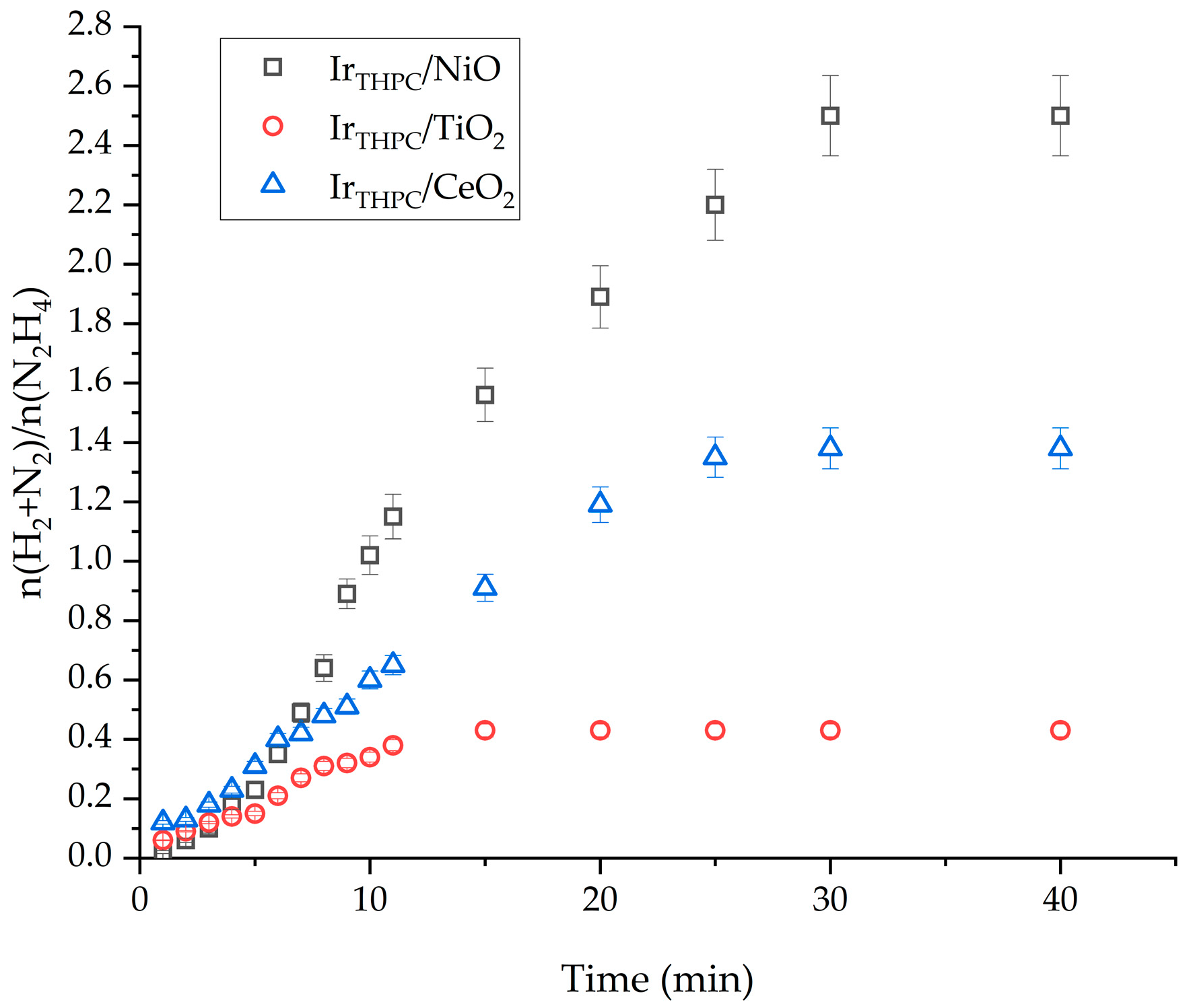
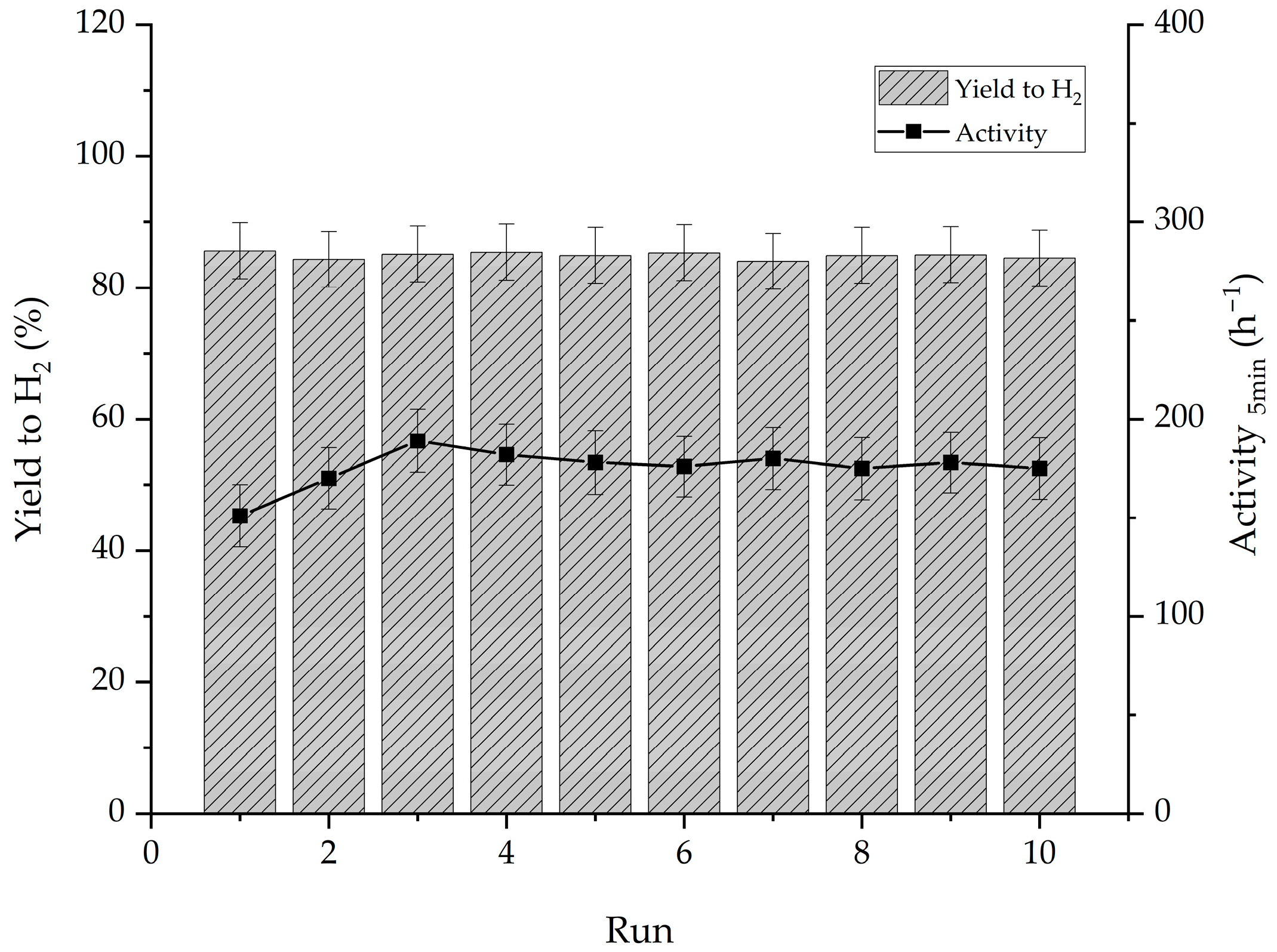
2.2. Influence of the Support Material

Other than the active metal and the preparation method chosen for the synthesis of a catalyst, an important role in its final catalytic performance is played by the choice of support on which the nanoparticles are deposited [42,43,44]. A series of Ir-based catalysts were prepared using the sol immobilization THPC method. CeO2, the reference oxide material, was compared with TiO2 and NiO to better identify if the catalytic performance of the material tested is related to its acid-base properties. Considering the point of zero charge (PZC) reported in the literature for these oxides, we can classify TiO2 as the more acidic support, with a PZC of 4–5 and NiO as the more basic one, with a PZC of 8–9, while CeO2 can be considered more neutral, with a PZC of 6–8 [45]. The sol immobilization protocol with THPC as a protective and reducing agent was chosen because it allows ultrasmall Ir nanoparticles to be produced and the same particle morphology to be maintained regardless of the support used [36]. Indeed, TEM analysis showed that the Ir particle size is almost the same (~1 nm) for IrTHPC/CeO2, IrTHPC/TiO2 and IrTHPC/NiO (Table 1) and Ref. [36]. Moreover, in all cases, narrow particle distribution was obtained [36] and immobilization was almost quantitative with the theoretical loading value (1%) (Table 1). The SEM images of IrTHPC/NiO also show good Ir dispersion on the supports (Figure 2).
In contrast, XPS analysis reveals significant discrepancies in the concentration of Ir species on the surface (Table 1). The highest Ir percentage at the surface (1.73%) of IrTHPC/NiO compared to IrTHPC/CeO2 and IrTHPC/TiO2 (0.86 and 0.40%, respectively) can be attributed to the higher surface of NiO (300 m2 g−1) compared to the other supports (40–60 m2 g−1 [45] High-resolution Ir 4f spectra of IrTHPC/NiO and IrTHPC/TiO2 were recorded and compared to IrTHPC/CeO2 (Table 1, Figure S3). Similar to IrTHPC/CeO2 and IrTHPC/NiO, Ir 4f7/2 and Ir 4f5/2 components can be split into two peaks, whereas for IrTHPC/TiO2, the overlapping of the Ir 4f signal with the Ti 3s peak does not allow such distinction. In IrTHPC/NiO, the peak centered at 60.9 eV can be associated with metallic Ir, whereas the Ir(IV) contribution is centered at 62.5 eV. It should be mentioned that for the NiO catalyst, a typical BE value for Ir0 was observed, excluding evident charge transfer phenomena between NiO and Ir.
The catalytic activity of the three catalysts was evaluated (Figure 3). The initial activity followed the order IrTHPC/CeO2 (1740 h−1) > IrTHPC/TiO2 (984 h−1) > IrTHPC/NiO (151 h−1) (Table 1). The first two catalysts reached full conversion after 25 min, whereas the NiO-based catalyst reached full conversion only after 30 min (Figure 3). The three catalysts have similar particle size and oxidation states; therefore, we can exclude these descriptors as the main parameters of the activity. However, the Ir–support charge transfer observed in IrTHPC/CeO2 could be responsible for the higher activity of this catalyst. Strong metal–support interaction between ceria and Ir has already been shown to positively influence activity in furfural hydrogenation [36] and CO2 hydrogenation [46]. No direct correlation between activity and the acid-base properties of the support was envisaged.
In terms of hydrogen production, IrTHPC/NiO presented a final yield of hydrogen of 83.9%, more than double the one exhibited by IrTHPC/CeO2 (36.6%) and IrTHPC/TiO2 (4.5%) (Table 1). This catalytic performance is interesting as, despite the lower activity, the higher yield of hydrogen makes it more appealing for practical application, reducing the waste of hydrous hydrazine for the production of hydrogen. These catalytic properties could be related to the inclusion of the Ni atom into the Ir nanoparticles, as the literature reports that bimetallic Ir-Ni nanoparticles display higher values of yield of molecular hydrogen for this reaction. The inclusion of the Ni atom probably happens during the reaction due to the small dissolution of the support in the medium. Indeed, XPS analysis of the used catalyst evidenced a slight shift of the Ir0 component to a higher BE (61.2 eV), probably due to stronger metal–support interaction. However, a more detailed characterization is required to solve the real nature and structure of these nanoparticles.
The stability of IrTHPC/NiO, the most selective catalyst, was evaluated (Figure 4).
Over the course of ten recycling reactions performed by adding fresh aqueous hydrous hydrazine to the mixture at the end of the reaction, the yield remained almost constant during all cycles. The stability shown by the Ir/NiO sample is probably associated with the high final yield of hydrogen from this sample. The production of ammonia and its successive absorption on the metal surface can be correlated to the deactivation of the iridium catalysts due to the high desorption energy of this molecule that can remain on the surface and block the active sites of the catalyst, therefore, poisoning it, as described by the DFT in a previous paper [47]. The increase in the activity exhibited in the first few runs, reaching a maximum value of (189 h−1) in the third run, is ascribed to the reconstruction of the surface of the metal nanoparticle during the reaction because of the exposure to the high pH of the reaction environment, as evidenced by the XPS analysis of the used catalyst (Table 1). ICP-MS analysis on the solution remaining after the tenth reaction showed limited leaching for Ir, only 2.2% of the total iridium was used in ten reactions, almost no Ni was found in the solution, and 0.01% of the initial Ni was used for the reaction. This is another indication of the high stability of IrTHPC/NiO for the decomposition of hydrous hydrazine in the liquid phase.

3. Materials and Methods

3.1. Catalyst Preparation

3.1.1. Supported Ir Catalyst Preparation using Deposition–Precipitation/NaOH

In a 100 mL beaker, 50 mL of distilled water and the support were added and stirred. A NaOH solution of 0.1 M was added dropwise until the desired pH (10) was reached. When the pH of the dispersion was stable, the desired amount of the Ir precursor (K2IrCl6, Alfa-Aesar 99% purity) was added (nominal Ir loading 1%). The pH was adjusted continuously to 10 by adding NaOH aqueous solution, and it was kept constant at that value for 8 h (CeO2, Sigma-Aldrich, St. Louis, MO, USA). The catalyst was then filtered, dried in an oven at 110 °C and, finally, reduced at 600 °C to obtain metallic nanoparticles. The heat treatment was performed in a horizontal furnace, equipped with a quartz tube, capable of reaching temperatures as high as 800 °C. Reduction step was performed under a flow of 10% H2 in Ar, 80 mL min−1, with a temperature increase of 10 °C/min until a heat-treatment temperature of 600 °C was reached. After reaching the final heat-treatment temperature, the sample was kept at the desired temperature for 3 h.

3.1.2. Supported Ir Catalyst Preparation Using Deposition–Precipitation/Urea

First, the support (CeO2, Sigma-Aldrich, St. Louis, MO, USA) was added with the salt precursor (K2IrCl6, Alfa-Aesar 99% purity) to 400 mL of deionized water, and then, the dispersion was heated to 80 °C and kept at that temperature. When the temperature was constant, the desired amount of urea was then added and left to react for 3 h after pH 7 was finally reached. Urea in acidic solution hydrolyzes producing ammonia that gradually raises the pH to a value of 7 and acts as a precipitation agent. The catalyst was then filtered, dried in an oven at 110 °C, calcined at 300 °C and, finally, reduced at 600 °C to obtain metallic nanoparticles. The heat treatment was performed in a horizontal furnace, equipped with a quartz tube, capable of reaching temperatures as high as 800 °C using a calcination boat in ceramic to contain the catalyst powder during the treatment. Reduction step was performed under a flow of 10% H2 in Ar, 80 mL min−1, with a temperature increase of 10 °C/min until a heat-treatment temperature of 600 °C was reached. After reaching the final heat-treatment temperature, the sample was kept at the desired temperature for 3 h.

3.1.3. Supported Ir Catalyst Preparation Using THPC/NaOH Colloidal Method

Iridium nanoparticles were prepared using tetrakis(hydroxymethyl)phosphonium chloride (THPC), which acts as both reductant and protecting agent. A fresh aqueous solution of THPC (0.0675 M) and NaOH (0.2 M) was added to 50 mL of deionized water under stirring to achieve a NaOH/THPC molar ratio of 3:2. After a few minutes, an aqueous solution of the iridium precursor (H2IrCl6, 3.25 mg L−1) was introduced in order to obtain a THPC/Ir molar ratio of 4:3 and left under continuous stirring. After 30 min, the support was added to the solution (the amount of support was calculated in order to obtain an Ir loading of 1%). The slurry was left under stirring for 1 h before it was filtered. The catalyst was washed thoroughly with deionized water (1 L) to remove the residues of the reduction reaction and dried at 90 °C overnight under static air. This methodology was used to investigate the support effect. Commercial CeO2, commercial TiO2 and NiO prepared following the method reported in Ref. [45] were used.

3.2. Catalyst Characterization

The catalysts were thoroughly characterized using X-ray photoelectron spectroscopy (XPS), transmission electron microscopy (TEM), scanning electron microscopy/SEM) and inductively coupled plasma mass spectroscopy (ICP-MS).
A detailed description of the instrument and the procedures used are reported in Ref. [29]. In brief, Thermo Scientific K-α+ spectrometer (Thermo Fisher Scientific, Waltham, MA, USA) was used to perform X-ray photoelectron spectroscopy (XPS) analyses. The spectrometer uses a monochromatic Al X-ray source operating at 72 W (6 mA × 12 kV). The experimental spectra were fitted after subtraction of Shirley [48,49] or U2 Tougaard background using CasaXPS (v2.3.17 PR1.1) and Scofield sensitivity factors with an energy exponent of −0.6.
The morphology of the catalyst was evaluated using transmission electron microscopy with a JEOL JEM 2100 TEM (JEOL Gmbh, Freising, Germany) operating at 200 keV. In order to obtain a reliable mean nanoparticle size of the desired metal nanoparticle determination, at least 200 particles from different areas were measured.
The sample was analyzed using scanning electron microscopy performed on a Tescan (Tescan, Brno, Czech Republic) Maia3 field emission gun scanning electron microscope (FEG-SEM) fitted with an Oxford Instruments XMAXN 80 energy dispersive X-ray detector (EDX). Images were acquired using secondary electron and backscattered electron detectors. Samples were dispersed as a powder onto 300 mesh copper grids coated with holey carbon film.
The relative elemental composition can be assessed using EDX, as the quantity of X-rays emitted at specific energy values is proportional to the amount of each specific atom.
ICP-MS analyses of solutions of the preparation of catalyst, after the filtration and separation of the solid catalyst, were performed to quantify the amount of metal that was not immobilized/deposited during the preparation of the catalysts. The analyses were performed on an Agilent 7900 ICP-MS (Agilent Technologies, Santa Clara, CA, USA).

3.3. Catalytic Tests

The experimental details, including the calculation of hydrogen yield, are already reported in Ref. [29]. The decomposition of hydrous hydrazine was followed either by the volume of gas produced and then by colorimetric analysis. In brief, the typical catalytic tests were performed in a sealed batch reactor, and the volume of gas produced was quantified using a burette filled with water and rotated upside-down in a beaker filled with water. The set-up is composed of a single-neck sealed cap round-bottom flask used as reactor. The typical experimental protocol for the reaction was the following: the weighted mass of the desired catalyst was added to the reactor with 8 mL of NaOH (0.5 M) solution in water. The reactor was placed in an oil bath on a magnetic stirring hot plate, which was set to reach a chosen temperature. The temperature of reaction was 50 °C. When the reaction temperature was reached, 0.3 mL of 3.3 M hydrous hydrazine solution was added, and stirring was initiated again to start the reaction.
Reusability tests were performed following the same experimental procedure of the batch reaction quantified using the volumetric method. From the second reaction, fresh hydrous hydrazine solution was added to restart the experimental test, while the catalyst was kept in the reaction solution between reaction cycles.

4. Conclusions

In the present work, Ir/CeO2 prepared using deposition–precipitation with NaOH or urea as the precipitating agent and prepared using the sol immobilization method with THPC as the protective and reducing agent were evaluated in hydrous hydrazine liquid-phase decomposition. IrTHPC/CeO2 and IrDPNaOH/CeO2 showed the best activity and yield of H2 compared to IrDPurea/CeO2. Both the activity and selectivity can be explained in terms of Ir particle size. Indeed, as reported in the literature, the small Ir particles observed for IrTHPC/CeO2 and IrDPNaOH/CeO2 (1.1 and 0.8 nm) enhanced both the activity and selectivity. In contrast, the large particles (3.6 nm) observed for IrDPurea/CeO2 resulted in lower activity and promoted the production of undesired pathways with the formation of NH3 and N2. Using THPC as the protective agent and reducing agent, the effect of the support on the activity of Ir particles was investigated. Higher activity was observed for IrTHPC/CeO2, which showed a strong metal–support interaction with a charge transfer from Ir to CeO2, with the formation of positively charged Irδ+. In contrast, IrTHPC/NiO, despite the lower activity, showed the highest yield of H2 (83.9%). The high selectivity can be attributed to the formation of Ir-Ni species during the reaction, which is demonstrated to promote the complete reforming of hydrous hydrazine. Moreover, the catalysts showed good stability both in terms of activity and the yield of hydrogen after 10 recycles.

Supplementary Materials

The following supporting information can be downloaded at: https://www.mdpi.com/article/10.3390/catal14020119/s1, Figure S1. TEM images and particle distribution; Figure S2. XPS Ir 4f spectra; Figure S3. SEM images of IrDPurea/CeO2.

Author Contributions

Conceptualization, A.V. and N.D.; methodology, S.B.; validation, S.B., D.M. and M.S.; formal analysis, M.S.; writing—original draft preparation, S.B.; writing—review and editing, A.V., N.D. and L.P. All authors have read and agreed to the published version of the manuscript.

Funding

This research was funded by the National Recovery and Resilience Plan (NRRP), Mission 4 Component 2 Investment 1.3—Call for tender No. 1561 of 11.10.2022 of Ministero dell’Università e della Ricerca (MUR) and the European Union—NextGenerationEU, Award Number: Project code PE0000021, Concession Decree No. 1561 of 11.10.2022 adopted by Ministero dell’Università e della Ricerca (MUR), CUP D43C22003090001, Project title “Network 4 Energy Sustainable Transition—NEST”.

Data Availability Statement

The data presented in this study are available.

Acknowledgments

The authors would like to thank the EPSRC for their financial support. Davide Motta wishes to thank the EPSRC Catalysis CDT (EP/L016443/1) for the PhD scholarship.

Conflicts of Interest

The authors declare no conflicts of interest.

References

  1. Yue, M.; Lambert, H.; Pahon, E.; Roche, R.; Jemei, S.; Hissel, D. Hydrogen energy systems: A critical review of technologies, applications, trends and challenges. Renew. Sustain. Energy Rev. 2021, 146, 111180. [Google Scholar] [CrossRef]
  2. Ji, M.; Wang, J. Review and comparison of various hydrogen production methods based on costs and life cycle impact assessment indicators. Int. J. Hydrogen Energy 2021, 46, 38612–38635. [Google Scholar] [CrossRef]
  3. Atilhan, S.; Park, S.; El-Halwagi, M.M.; Atilhan, M.; Moore, M.; Nielsen, R.B. Green hydrogen as an alternative fuel for the shipping industry. Curr. Opin. Chem. Eng. 2021, 31, 100668. [Google Scholar] [CrossRef]
  4. Kumar, S.S.; Himabindu, V. Hydrogen production by PEM water electrolysis—A review. Mater. Sci. Energy Technol. 2019, 2, 442–454. [Google Scholar] [CrossRef]
  5. Pareek, A.; Dom, R.; Gupta, J.; Chandran, J.; Adepu, V.; Borse, P.H. Insights into renewable hydrogen energy: Recent advances and prospects. Mater. Sci. Energy Technol. 2020, 3, 319–327. [Google Scholar] [CrossRef]
  6. Mazloomi, K.; Gomes, C. Hydrogen as an energy carrier: Prospects and challenges. Renew. Sustain. Energy Rev. 2012, 16, 3024–3033. [Google Scholar] [CrossRef]
  7. Ramachandran, R.; Menon, R.K. An overview of industrial uses of hydrogen. Int. J. Hydrogen Energy 1998, 23, 593–598. [Google Scholar] [CrossRef]
  8. Tarkowski, R. Underground hydrogen storage: Characteristics and prospects. Renew. Sustain. Energy Rev. 2019, 105, 86–94. [Google Scholar] [CrossRef]
  9. Yadav, M.; Xu, Q. Liquid-phase chemical hydrogen storage materials. Energy Environ. Sci. 2012, 5, 9698. [Google Scholar] [CrossRef]
  10. Cheng, Y.; Wu, X.; Xu, H. Catalytic decomposition of hydrous hydrazine for hydrogen production. Sustain. Energy Fuels 2018, 3, 343–365. [Google Scholar] [CrossRef]
  11. Matyshak, V.A.; Silchenkova, O.N. Catalytic Decomposition of Hydrazine and Hydrazine Derivatives to Produce Hydrogen-Containing Gas Mixtures: A Review. Kinet. Catal. 2022, 63, 339–350. [Google Scholar] [CrossRef]
  12. Zhang, P.-X.; Wang, Y.-G.; Huang, Y.-Q.; Zhang, T.; Wu, G.-S.; Li, J. Density functional theory investigations on the catalytic mechanisms of hydrazine decompositions on Ir(111). Catal. Today 2011, 165, 80–88. [Google Scholar] [CrossRef]
  13. Zheng, M.; Chen, X.; Cheng, R.; Li, N.; Sun, J.; Wang, X.; Zhang, T. Catalytic decomposition of hydrazine on iron nitride catalysts. Catal. Commun. 2006, 7, 187–191. [Google Scholar] [CrossRef]
  14. Chen, X.; Zhang, T.; Xia, L.; Li, T.; Zheng, M.; Wu, Z.; Wang, X.; Wei, Z.; Xin, Q.; Li, C. Catalytic Decomposition of Hydrazine over Supported Molybdenum Nitride Catalysts in a Monopropellant Thruster. Catal. Lett. 2002, 79, 21–25. [Google Scholar] [CrossRef]
  15. McKay, H.L.; Jenkins, S.J.; Wales, D.J. Dissociative Chemisorption of Hydrazine on an Fe{211} Surface. J. Phys. Chem. C 2011, 115, 17812–17828. [Google Scholar] [CrossRef]
  16. Song-Il, O.; Yan, J.-M.; Wang, H.-L.; Wang, Z.-L.; Jiang, Q. High catalytic kinetic performance of amorphous CoPt NPs induced on CeO for H2 generation from hydrous hydrazine. Int. J. Hydrogen Energy 2014, 39, 3755–3761. [Google Scholar] [CrossRef]
  17. He, L.; Huang, Y.; Wang, A.; Wang, X.; Chen, X.; Delgado, J.J.; Zhang, T. A Noble-Metal-Free Catalyst Derived from Ni-Al Hydrotalcite for Hydrogen Generation from N2H4·H2O Decomposition. Angew. Chem. Int. Ed. 2012, 51, 6191–6194. [Google Scholar] [CrossRef]
  18. Kang, W.; Varma, A. Hydrogen generation from hydrous hydrazine over Ni/CeO2 catalysts prepared by solution combustion synthesis. Appl. Catal. B Environ. 2018, 220, 409–416. [Google Scholar] [CrossRef]
  19. Sanabria-Chinchilla, J.; Asazawa, K.; Sakamoto, T.; Yamada, K.; Tanaka, H.; Strasser, P. Noble Metal-Free Hydrazine Fuel Cell Catalysts: EPOC Effect in Competing Chemical and Electrochemical Reaction Pathways. J. Am. Chem. Soc. 2011, 133, 5425–5431. [Google Scholar] [CrossRef]
  20. Huang, W.; Liu, X. The “on–off” switch for on-demand H2 evolution from hydrous hydrazine over Ni8Pt1/C nano-catalyst. Fuel 2022, 315, 123210. [Google Scholar] [CrossRef]
  21. Yao, Q.; Long, J.; Yang, K.; Li, X.; Huang, B.; Chen, X.; Lu, Z.-H. Alkali-assisted synthesis of ultrafine NiPt nanoparticles immobilized on La2O2CO3 for highly efficient dehydrogenation of hydrous hydrazine and hydrazine borane. Catal. Today 2022, 400–401, 49–58. [Google Scholar] [CrossRef]
  22. Singh, S.K.; Zhang, X.-B.; Xu, Q. Room-Temperature Hydrogen Generation from Hydrous Hydrazine for Chemical Hydrogen Storage. J. Am. Chem. Soc. 2009, 131, 9894–9895. [Google Scholar] [CrossRef]
  23. Singh, S.K.; Iizuka, Y.; Xu, Q. Nickel-palladium nanoparticle catalyzed hydrogen generation from hydrous hydrazine for chemical hydrogen storage. Int. J. Hydrogen Energy 2011, 36, 11794–11801. [Google Scholar] [CrossRef]
  24. Singh, S.K.; Xu, Q. Complete Conversion of Hydrous Hydrazine to Hydrogen at Room Temperature for Chemical Hydrogen Storage. J. Am. Chem. Soc. 2009, 131, 18032–18033. [Google Scholar] [CrossRef]
  25. Wood, S.E.; Bryant, J.T. Decomposition of Hydrazine on Shell 405 Catalyst at High Presure. Prod. R&D 1973, 12, 117–122. [Google Scholar] [CrossRef]
  26. Jang, Y.B.; Kim, T.H.; Sun, M.H.; Lee, J.; Cho, S.J. Preparation of iridium catalyst and its catalytic activity over hydrazine hydrate decomposition for hydrogen production and storage. Catal. Today 2009, 146, 196–201. [Google Scholar] [CrossRef]
  27. Bellomi, S.; Barlocco, I.; Chen, X.; Delgado, J.J.; Arrigo, R.; Dimitratos, N.; Roldan, A.; Villa, A. Enhanced stability of sub-nanometric iridium decorated graphitic carbon nitride for H2 production upon hydrous hydrazine decomposition. Phys. Chem. Chem. Phys. 2022, 25, 1081–1095. [Google Scholar] [CrossRef] [PubMed]
  28. Prasad, V.; Vasanthkumar, M.S. Iridium-decorated multiwall carbon nanotubes and its catalytic activity with Shell 405 in hydrazine decomposition. J. Nanoparticle Res. 2015, 17, 1–8. [Google Scholar] [CrossRef]
  29. Motta, D.; Barlocco, I.; Bellomi, S.; Villa, A.; Dimitratos, N. Hydrous Hydrazine Decomposition for Hydrogen Production Using of Ir/CeO2: Effect of Reaction Parameters on the Activity. Nanomaterials 2021, 11, 1340. [Google Scholar] [CrossRef] [PubMed]
  30. Cuenya, B.R. Synthesis and catalytic properties of metal nanoparticles: Size, shape, support, composition, and oxidation state effects. Thin Solid Films 2010, 518, 3127–3150. [Google Scholar] [CrossRef]
  31. Guczi, L.; Horváth, D.; Pászti, Z.; Tóth, L.; Horváth, Z.E.; Karacs, A.; Petõ, G. Modeling Gold Nanoparticles: Morphology, Electron Structure, and Catalytic Activity in CO Oxidation. J. Phys. Chem. B 2000, 104, 3183–3193. [Google Scholar] [CrossRef]
  32. Henry, C.R. Morphology of supported nanoparticles. Prog. Surf. Sci. 2005, 80, 92–116. [Google Scholar] [CrossRef]
  33. Munnik, P.; de Jongh, P.E.; de Jong, K.P. Recent Developments in the Synthesis of Supported Catalysts. Chem. Rev. 2015, 115, 6687–6718. [Google Scholar] [CrossRef]
  34. He, L.; Liang, B.; Li, L.; Yang, X.; Huang, Y.; Wang, A.; Wang, X.; Zhang, T. Cerium-Oxide-Modified Nickel as a Non-Noble Metal Catalyst for Selective Decomposition of Hydrous Hydrazine to Hydrogen. ACS Catal. 2015, 5, 1623–1628. [Google Scholar] [CrossRef]
  35. He, L.; Liang, B.; Huang, Y.; Zhang, T. Design strategies of highly selective nickel catalysts for H2 production via hydrous hydrazine decomposition: A review. Natl. Sci. Rev. 2017, 5, 356–364. [Google Scholar] [CrossRef]
  36. Campisi, S.; Motta, D.; Barlocco, I.; Stones, R.; Chamberlain, T.W.; Chutia, A.; Dimitratos, N.; Villa, A. Furfural Adsorption and Hydrogenation at the Oxide-Metal Interface: Evidence of the Support Influence on the Selectivity of Iridium-Based Catalysts. ChemCatChem 2022, 14, e202101700. [Google Scholar] [CrossRef]
  37. Wang, W.; Villa, A.; Kuebel, C.; Hahn, H.; Wang, D. Tailoring the 3D Structure of Pd Nanocatalysts Supported on Mesoporous Carbon for Furfural Hydrogenation. Chemnanomat 2018, 4, 1125–1132. [Google Scholar] [CrossRef]
  38. Freakley, S.J.; Ruiz-Esquius, J.; Morgan, D.J. The X-ray photoelectron spectra of Ir, IrO2 and IrCl3 revisited. Surf. Interface Anal. 2017, 49, 794–799. [Google Scholar] [CrossRef]
  39. Lykhach, Y.; Kubát, J.; Neitzel, A.; Tsud, N.; Vorokhta, M.; Skála, T.; Dvořák, F.; Kosto, Y.; Prince, K.C.; Matolín, V.; et al. Charge transfer and spillover phenomena in ceria-supported iridium catalysts: A model study. J. Chem. Phys. 2019, 151, 204703. [Google Scholar] [CrossRef]
  40. Lee, S.; Fan, C.; Wu, T.; Anderson, S.L. Hydrazine Decomposition over Irn/Al2O3 Model Catalysts Prepared by Size-Selected Cluster Deposition. J. Phys. Chem. B 2004, 109, 381–388. [Google Scholar] [CrossRef]
  41. Fan, C.; Wu, T.; Kaden, W.E.; Anderson, S.L. Cluster size effects on hydrazine decomposition on Irn/Al2O3/NiAl(110). Surf. Sci. 2006, 600, 461–467. [Google Scholar] [CrossRef]
  42. Parapat, R.Y.; Saputra, O.H.I.; Ang, A.P.; Schwarze, M.; Schomäcker, R. Support effect in the preparation of supported metal catalysts via microemulsion. RSC Adv. 2014, 4, 50955–50963. [Google Scholar] [CrossRef]
  43. Lou, Y.; Xu, J.; Zhang, Y.; Pan, C.; Dong, Y.; Zhu, Y. Metal-support interaction for heterogeneous catalysis: From nanoparticles to single atoms. Mater. Today Nano 2020, 12, 100093. [Google Scholar] [CrossRef]
  44. Gerber, I.C.; Serp, P. A Theory/Experience Description of Support Effects in Carbon-Supported Catalysts. Chem. Rev. 2019, 120, 1250–1349. [Google Scholar] [CrossRef]
  45. Campisi, S.; Chan-Thaw, C.E.; Chinchilla, L.E.; Chutia, A.; Botton, G.A.; Mohammed, K.M.H.; Dimitratos, N.; Wells, P.P.; Villa, A. Dual-Site-Mediated Hydrogenation Catalysis on Pd/NiO: Selective Biomass Transformation and Maintenance of Catalytic Activity at Low Pd Loading. ACS Catal. 2020, 10, 5483–5492. [Google Scholar] [CrossRef]
  46. Li, S.; Xu, Y.; Chen, Y.; Li, W.; Lin, L.; Li, M.; Deng, Y.; Wang, X.; Ge, B.; Yang, C.; et al. Tuning the Selectivity of Catalytic Carbon Dioxide Hydrogenation over Iridium/Cerium Oxide Catalysts with a Strong Metal–Support Interaction. Angew. Chem. Int. Ed. 2017, 56, 10761–10765. [Google Scholar] [CrossRef]
  47. Lu, X.; Francis, S.; Motta, D.; Dimitratos, N.; Roldan, A. Mechanistic study of hydrazine decomposition on Ir(111). Phys. Chem. Chem. Phys. 2020, 22, 3883–3896. [Google Scholar] [CrossRef]
  48. Jiang, H.; Sun, X.; Du, Y.; Chen, R.; Xing, W. Catalytic activity of palladium nanoparticles immobilized on an amino-functionalized ceramic membrane support. Chin. J. Catal. 2014, 35, 1990–1996. [Google Scholar] [CrossRef]
  49. Shirley, D.A. High-Resolution X-Ray Photoemission Spectrum of the Valence Bands of Gold. Phys. Rev. B 1972, 5, 4709–4714. [Google Scholar] [CrossRef]
Figure 1. n(H2 + N2)/n(N2H2) versus time for hydrazine liquid-phase decomposition over IrDPNaOH/CeO2, IrDPurea/CeO2 and IrTHPC/CeO2, using 0.3 mL of 3.3 M hydrazine in 8 mL 0.5 M of NaOH solution at 50 °C.
Catalysts 14 00119 g001
Figure 2. Representative SEM images, (a), with EDX mapping of IrTHPC/NiO sample for different elements such as (b) O, (c) Ce and (d) Ir.
Catalysts 14 00119 g002
Figure 3. n(H2 + N2)/n(N2H2) versus time for hydrazine decomposition over IrTHPC/CeO2, IrTHPC/TiO2 and IrTHPC/NiO using 0.3 mL of 3.3 M hydrazine in 8 mL 0.5 M of NaOH solution at 50 °C.
Catalysts 14 00119 g003
Figure 4. Yield of molecular hydrogen and activity over the reusability tests on IrTHPC/NiO using 0.3 mL of 3.3 M hydrous hydrazine in 8 mL 0.5 M of NaOH solution at 50 °C.
Catalysts 14 00119 g004
Table 1. Bulk, surface properties and catalytic activity in hydrous hydrazine liquid-phase decomposition of Ir-based catalysts.
Catalyst XPSTEMIr Loading
(wt%)
Activity
(h−1)
H2 Yield
(%)
Ir 4fIr at (%)Ir NP Size (nm)
Ir0IrIV
IrDPNaOH/CeO2BE61.662.60.390.9 ± 0.20.70 ± 0.10154138.9
%87.612.4
IrDPurea/CeO2BE61.662.80.413.6 ± 0.50.98 ± 0.067410.7
%70.629.4
IrTHPC/CeO2BE61.762.60.861.1 ± 0.31.04 ± 0.13174036.6
%87.112.9
IrTHPC/TiO2BE60.9-0.401.3 ± 0.20.98 ± 0.089844.5
%100-
IrTHPC/NiOBE60.962.21.731.2 ± 0.31.00 ± 0.1015183.9
%84.915.1
IrTHPC/NiO after stability testsBE61.262.41.731.2 ± 0.31.00 ± 0.10--
%87.213.81.64n.d.0.98 ± 0.13
Disclaimer/Publisher’s Note: The statements, opinions and data contained in all publications are solely those of the individual author(s) and contributor(s) and not of MDPI and/or the editor(s). MDPI and/or the editor(s) disclaim responsibility for any injury to people or property resulting from any ideas, methods, instructions or products referred to in the content.

