
Ordered Mesoporous Nitrogen Dope Carbon Synthesized from Aniline for Stabilization of Ruthenium Species in CO2 Hydrogenation to Formate

 ,
, 
 ,
,  and
and 
Abstract

1. Introduction
2. Results and Discussion
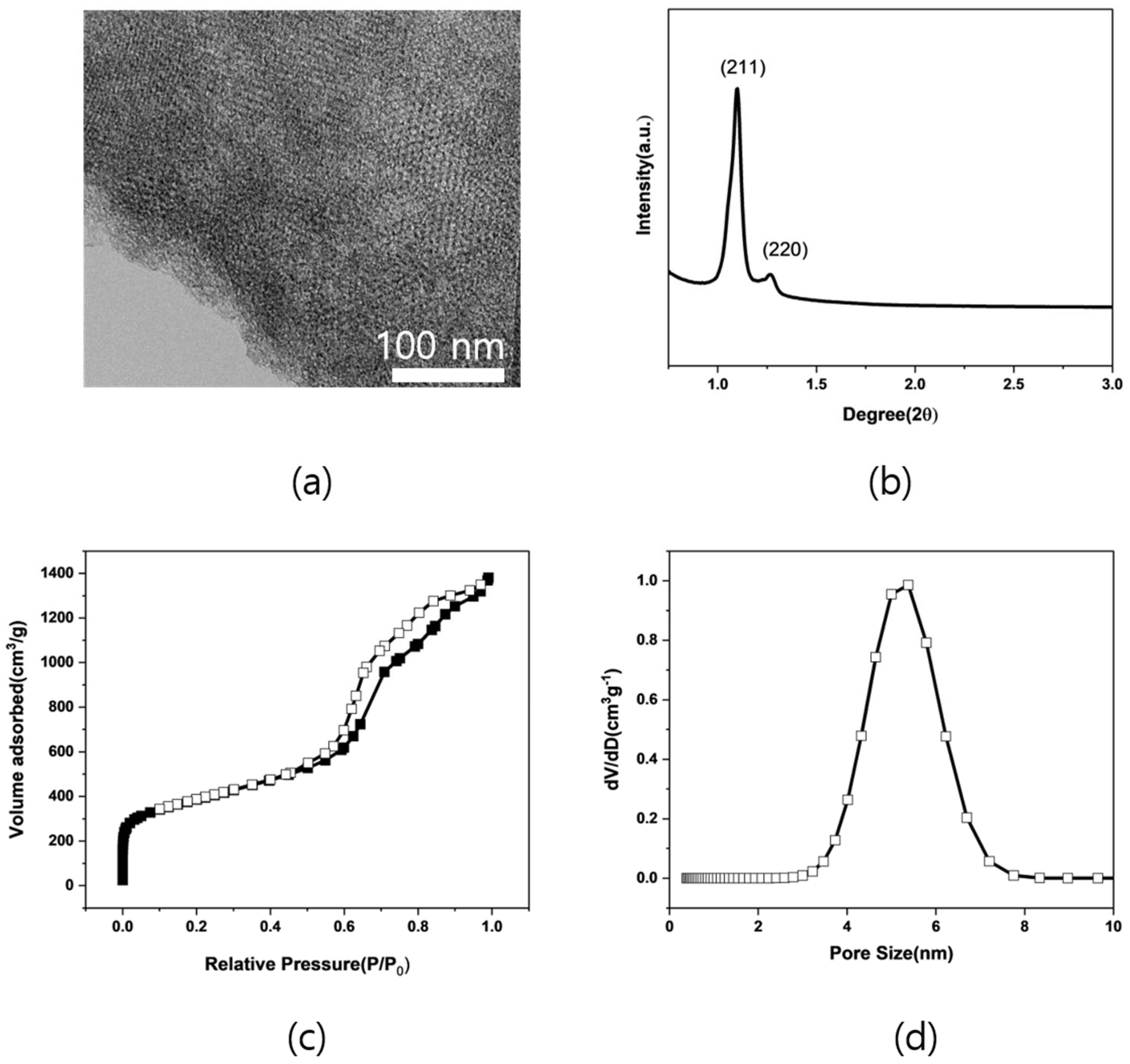
2.1. Characterization of Support Material
2.2. Catalytic Performance of Ru Supported on MNC-An
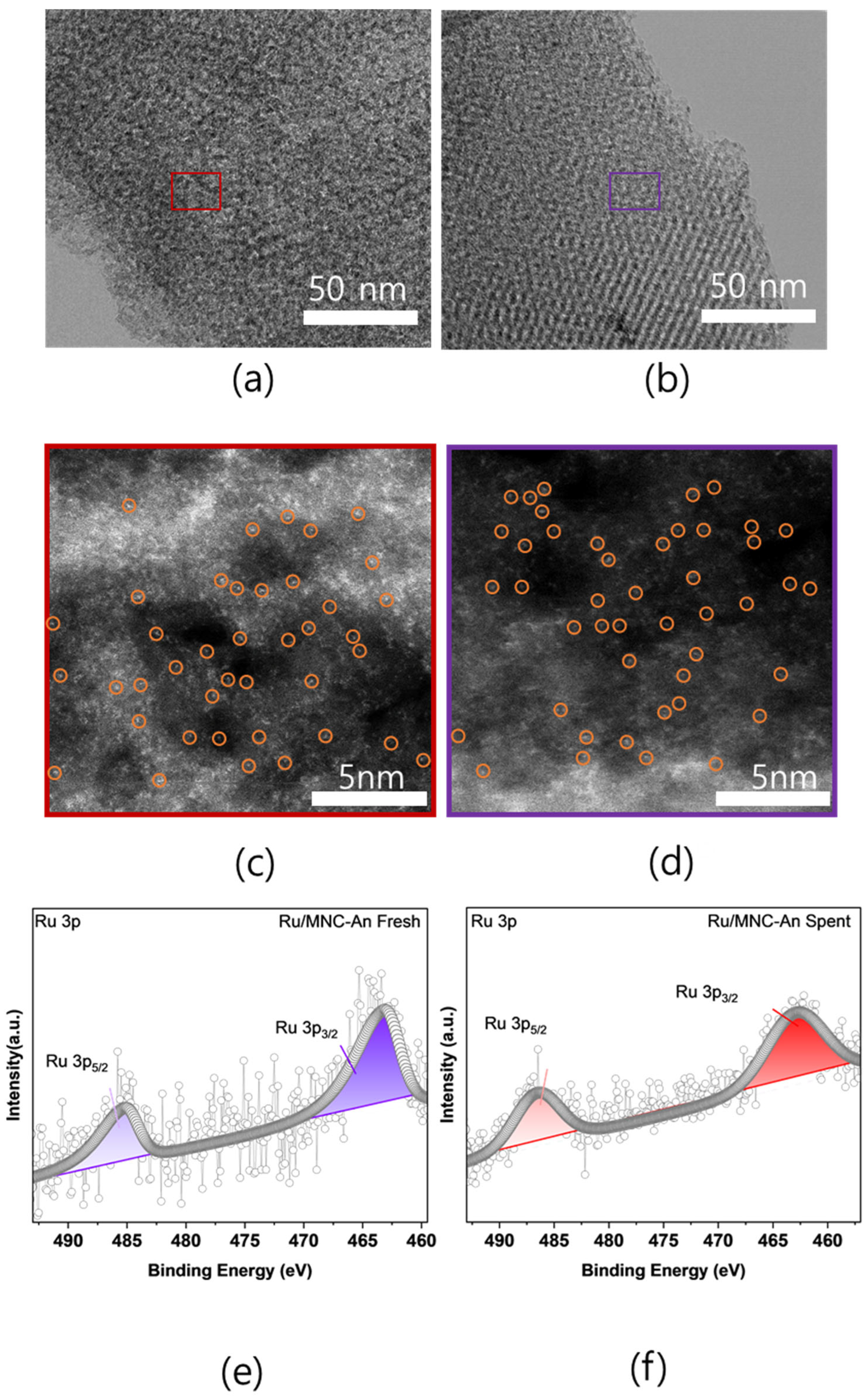
2.3. Physicochemical Properties of Fresh and Spent Ru/MNC-An
3. Materials and Methods
3.1. Materials
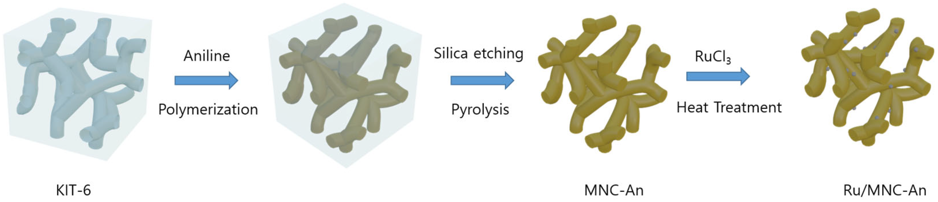
3.2. Preparation
3.3. Characterization
3.4. Operational Procedure for the CO2 Hydrogenation Reaction
3.5. Stability Test Procedure
4. Conclusions
Supplementary Materials
Author Contributions
Funding
Data Availability Statement
Conflicts of Interest
References
- Brandon, N.P.; Kurban, Z. Clean Energy and the Hydrogen Economy. Philos. Trans. R. Soc. A Math. Phys. Eng. Sci. 2017, 375, 20160400. [Google Scholar] [CrossRef] [PubMed]
- Sekine, Y.; Higo, T. Recent Trends on the Dehydrogenation Catalysis of Liquid Organic Hydrogen Carrier (LOHC): A Review. Top. Catal. 2021, 64, 470–480. [Google Scholar] [CrossRef]
- Kim, C.; Lee, Y.; Kim, K.; Lee, U. Implementation of Formic Acid as a Liquid Organic Hydrogen Carrier (LOHC): Techno-Economic Analysis and Life Cycle Assessment of Formic Acid Produced via CO2 Utilization. Catalysts 2022, 12, 1113. [Google Scholar] [CrossRef]
- Kim, C.; Park, K.; Lee, H.; Im, J.; Usosky, D.; Tak, K.; Park, D.; Chung, W.; Han, D.; Yoon, J.; et al. Accelerating the Net-Zero Economy with CO2-Hydrogenated Formic Acid Production: Process Development and Pilot Plant Demonstration. Joule 2024, 8, 693–713. [Google Scholar] [CrossRef]
- Liu, X.; Li, S.; Liu, Y.; Cao, Y. Formic Acid: A Versatile Renewable Reagent for Green and Sustainable Chemical Synthesis. Cuihua Xuebao/Chin. J. Catal. 2015, 36, 1461–1475. [Google Scholar] [CrossRef]
- Rumayor, M.; Dominguez-Ramos, A.; Irabien, A. Formic Acid Manufacture: Carbon Dioxide Utilization Alternatives. Appl. Sci. 2018, 8, 914. [Google Scholar] [CrossRef]
- Supronowicz, W.; Ignatyev, I.A.; Lolli, G.; Wolf, A.; Zhao, L.; Mleczko, L. Formic Acid: A Future Bridge between the Power and Chemical Industries. Green Chem. 2015, 17, 2904–2911. [Google Scholar] [CrossRef]
- Dutta, I.; Chatterjee, S.; Cheng, H.; Parsapur, R.K.; Liu, Z.; Li, Z.; Ye, E.; Kawanami, H.; Low, J.S.C.; Lai, Z.; et al. Formic Acid to Power towards Low-Carbon Economy. Adv. Energy Mater. 2022, 12, 2103799. [Google Scholar] [CrossRef]
- Nam, D.H.; De Luna, P.; Rosas-Hernández, A.; Thevenon, A.; Li, F.; Agapie, T.; Peters, J.C.; Shekhah, O.; Eddaoudi, M.; Sargent, E.H. Molecular Enhancement of Heterogeneous CO2 Reduction. Nat. Mater. 2020, 19, 266–276. [Google Scholar] [CrossRef]
- Jaleel, A.; Kim, S.H.; Natarajan, P.; Gunasekar, G.H.; Park, K.; Yoon, S.; Jung, K.D. Hydrogenation of CO2 to Formates on Ruthenium(III) Coordinated on Melamine Polymer Network. J. CO2 Util. 2020, 35, 245–255. [Google Scholar] [CrossRef]
- Wang, S.; Hou, S.; Wu, C.; Zhao, Y.; Ma, X. RuCl3 Anchored onto Post-Synthetic Modification MIL-101(Cr)-NH2 as Heterogeneous Catalyst for Hydrogenation of CO2 to Formic Acid. Chin. Chem. Lett. 2019, 30, 398–402. [Google Scholar] [CrossRef]
- Wu, C.; Irshad, F.; Luo, M.; Zhao, Y.; Ma, X.; Wang, S. Ruthenium Complexes Immobilized on an Azolium Based Metal Organic Framework for Highly Efficient Conversion of CO2 into Formic Acid. ChemCatChem 2019, 11, 1256–1263. [Google Scholar] [CrossRef]
- Gunasekar, G.H.; Shin, J.; Jung, K.D.; Park, K.; Yoon, S. Design Strategy toward Recyclable and Highly Efficient Heterogeneous Catalysts for the Hydrogenation of CO2 to Formate. ACS Catal. 2018, 8, 4346–4353. [Google Scholar] [CrossRef]
- Gunasekar, G.H.; Jung, K.D.; Yoon, S. Hydrogenation of CO2 to Formate Using a Simple, Recyclable, and Efficient Heterogeneous Catalyst. Inorg. Chem. 2019, 58, 3717–3723. [Google Scholar] [CrossRef] [PubMed]
- Park, K.; Gunasekar, G.H.; Kim, S.H.; Park, H.; Kim, S.; Park, K.; Jung, K.D.; Yoon, S. CO2 Hydrogenation to Formic Acid over Heterogenized Ruthenium Catalysts Using a Fixed Bed Reactor with Separation Units. Green Chem. 2020, 22, 1639–1649. [Google Scholar] [CrossRef]
- Yang, Z.Z.; Zhang, H.; Yu, B.; Zhao, Y.; Ji, G.; Liu, Z. A Tröger’s Base-Derived Microporous Organic Polymer: Design and Applications in CO2/H2 Capture and Hydrogenation of CO2 to Formic Acid. Chem. Commun. 2015, 51, 1271–1274. [Google Scholar] [CrossRef]
- Eder, G.M.; Pyles, D.A.; Wolfson, E.R.; McGrier, P.L. A Ruthenium Porphyrin-Based Porous Organic Polymer for the Hydrosilylative Reduction of CO2 to Formate. Chem. Commun. 2019, 55, 7195–7198. [Google Scholar] [CrossRef]
- Kann, A.; Hartmann, H.; Besmehn, A.; Hausoul, P.J.C.; Palkovits, R. Hydrogenation of CO2 to Formate over Ruthenium Immobilized on Solid Molecular Phosphines. ChemSusChem 2018, 11, 1857–1865. [Google Scholar] [CrossRef]
- Lo, H.-K.; Copéret, C. ETH Library CO2 Hydrogenation to Formate with Immobilized Ru-Catalysts Based on Hybrid Organo-Silica Mesostructured Materials. ChemCatChem 2019, 11, 430–434. [Google Scholar] [CrossRef]
- Mori, K.; Taga, T.; Yamashita, H. Isolated Single-Atomic Ru Catalyst Bound on a Layered Double Hydroxide for Hydrogenation of CO2 to Formic Acid. ACS Catal. 2017, 7, 3147–3151. [Google Scholar] [CrossRef]
- Chen, B.; Dong, M.; Liu, S.; Xie, Z.; Yang, J.; Li, S.; Wang, Y.; Du, J.; Liu, H.; Han, B. CO2 Hydrogenation to Formate Catalyzed by Ru Coordinated with a N,P-Containing Polymer. ACS Catal. 2020, 10, 8557–8566. [Google Scholar] [CrossRef]
- Wang, Z.; Hasegawa, S.; Motokura, K.; Kuang, S.; Yang, Y. A Single-Atom Pd Catalyst Anchored on a Porous Organic Polymer for Highly Efficient Telomerization of 1,3-Butadiene with Methanol. Ind. Eng. Chem. Res. 2023, 62, 3151–3156. [Google Scholar] [CrossRef]
- Huang, G.; Niu, Q.; Zhang, J.; Huang, H.; Chen, Q.; Bi, J.; Wu, L. Platinum Single-Atoms Anchored Covalent Triazine Framework for Efficient Photoreduction of CO2 to CH4. Chem. Eng. J. 2022, 427, 131018. [Google Scholar] [CrossRef]
- Yang, Z.; Chen, H.; Wang, S.; Guo, W.; Wang, T.; Suo, X.; Jiang, D.; Zhu, X.; Popovs, I.; Dai, S. Transformation Strategy for Highly Crystalline Covalent Triazine Frameworks: From Staggered AB to Eclipsed AA Stacking. J. Am. Chem. Soc. 2020, 142, 6856–6860. [Google Scholar] [CrossRef]
- Zhu, X.; Tian, C.; Mahurin, S.M.; Chai, S.-H.; Wang, C.; Brown, S.; Veith, G.M.; Luo, H.; Liu, H.; Dai, S. A Superacid-Catalyzed Synthesis of Porous Membranes Based on Triazine Frameworks for CO2 Separation. J. Am. Chem. Soc. 2012, 134, 10478–10484. [Google Scholar] [CrossRef]
- Jaleel, A.; Haider, A.; Van Nguyen, C.; Lee, K.R.; Choung, S.; Han, J.W.; Baek, S.H.; Shin, C.H.; Jung, K.D. Structural Effect of Nitrogen/Carbon on the Stability of Anchored Ru Catalysts for CO2 Hydrogenation to Formate. Chem. Eng. J. 2022, 433 Pt 2, 133571. [Google Scholar] [CrossRef]
- Ahn, S.; Park, K.; Lee, K.R.; Haider, A.; Van Nguyen, C.; Jin, H.; Yoo, S.J.; Yoon, S.; Jung, K.-D. Atomically Dispersed Ru(III) on N-Doped Mesoporous Carbon Hollow Spheres as Catalysts for CO2 Hydrogenation to Formate. Chem. Eng. J. 2022, 442 Pt 1, 136185. [Google Scholar] [CrossRef]
- Janus, R.; Natkański, P.; Wądrzyk, M.; Lewandowski, M.; Łątka, P.; Kuśtrowski, P. Effect of Solvent Polarity in Formation of Perfectly Ordered CMK-3 and CMK-5 Carbon Replicas by Precipitation Polycondensation of Furfuryl Alcohol. Microporous Mesoporous Mater. 2022, 329, 111542. [Google Scholar] [CrossRef]
- Daneluti, A.L.M.; Neto, F.M.; Velasco, M.V.R.; Baby, A.R.; do Rosário Matos, J. Evaluation and Characterization of the Encapsulation/Entrapping Process of Octyl Methoxycinnamate in Ordered Mesoporous Silica Type SBA-15. J. Therm. Anal. Calorim. 2018, 131, 789–798. [Google Scholar] [CrossRef]
- Le, H.T.T.; Dang, T.-D.; Chu, N.T.H.; Park, C.-J. Synthesis of Nitrogen-Doped Ordered Mesoporous Carbon with Enhanced Lithium Storage Performance from Natural Kaolin Clay. Electrochim. Acta 2020, 332, 135399. [Google Scholar] [CrossRef]
- Park, K.; Lee, K.R.; Ahn, S.; Kim, S.H.; Haider, A.; Choung, S.; Han, J.W.; Jung, K.D. Structural Effects of Nitrogen-Doped Titanium Oxide Supports on Stabilization of Ruthenium Active Species in Carbon Dioxide Hydrogenation to Formate. Appl. Catal. B 2023, 335, 122873. [Google Scholar] [CrossRef]
- Park, K.; Lee, K.R.; Ahn, S.; Van Nguyen, C.; Jung, K.D. Effects of the Chemical States of N Sites and Mesoporosity of N-Doped Carbon Supports on Single-Atom Ru Catalysts during CO2-to-Formate Conversion. Appl. Catal. B 2024, 346, 123751. [Google Scholar] [CrossRef]
- Lee, K.R.; Masudi, A.; Park, K.; Ahn, S.; Lee, J.S.; Sim, S.J.; Jung, K.D. Sustainable Approach for CO2 Hydrogenation to Formic Acid with Ru Single Atom Catalysts on Nitrogen-Doped Carbon Prepared from Green Algae. Chem. Eng. J. 2024, 494, 152922. [Google Scholar] [CrossRef]
- Lee, K.R.; Haider, A.; Park, K.; Ahn, S.; Jung, K.D. Sustainable Synthesis of N-Doped Carbon to Stabilize Ru Species for CO2 Hydrogenation to Formic Acid. J. CO2 Util. 2024, 86, 102896. [Google Scholar] [CrossRef]
- Ganji, N.; Karimi, B.; Najafvand-Derikvandi, S.; Vali, H. Palladium Supported on a Novel Ordered Mesoporous Polypyrrole/Carbon Nanocomposite as a Powerful Heterogeneous Catalyst for the Aerobic Oxidation of Alcohols to Carboxylic Acids and Ketones on Water. RSC Adv. 2020, 10, 13616–13631. [Google Scholar] [CrossRef]
- Weidenthaler, C.; Lu, A.H.; Schmidt, W.; Schüth, F. X-Ray Photoelectron Spectroscopic Studies of PAN-Based Ordered Mesoporous Carbons (OMC). Microporous Mesoporous Mater. 2006, 88, 238–243. [Google Scholar] [CrossRef]
- Xing, W.; Zhuo, S.; Cui, H.; Yan, Z. Synthesis of Polyaniline-Coated Ordered Mesoporous Carbon and Its Enhanced Electrochemical Properties. Mater. Lett. 2007, 61, 4627–4630. [Google Scholar] [CrossRef]
- Zhang, Z.; Wang, G.; Li, Y.; Zhang, X.; Qiao, N.; Wang, J.; Zhou, J.; Liu, Z.; Hao, Z. A New Type of Ordered Mesoporous Carbon/Polyaniline Composites Prepared by a Two-Step Nanocasting Method for High Performance Supercapacitor Applications. J. Mater. Chem. A Mater. 2014, 2, 16715–16722. [Google Scholar] [CrossRef]
- Rohland, P.; Schröter, E.; Nolte, O.; Newkome, G.R.; Hager, M.D.; Schubert, U.S. Redox-Active Polymers: The Magic Key towards Energy Storage—A Polymer Design Guideline Progress in Polymer Science. Prog. Polym. Sci. 2022, 125, 101474. [Google Scholar] [CrossRef]
- Quílez-Bermejo, J.; Morallón, E.; Cazorla-Amorós, D. Polyaniline-Derived N-Doped Ordered Mesoporous Carbon Thin Films: Efficient Catalysts towards Oxygen Reduction Reaction. Polymers 2020, 12, 2382. [Google Scholar] [CrossRef]
- Jeon, I.Y.; Noh, H.J.; Baek, J.B. Nitrogen-Doped Carbon Nanomaterials: Synthesis, Characteristics and Applications. Chem.-Asian J. 2020, 15, 2282–2293. [Google Scholar] [CrossRef] [PubMed]
- Billiet, L.; Fournier, D.; Du Prez, F. Step-Growth Polymerization and “click” Chemistry: The Oldest Polymers Rejuvenated. Polymer 2009, 50, 3877–3886. [Google Scholar] [CrossRef]
- Bednarczyk, K.; Matysiak, W.; Tański, T.; Janeczek, H.; Schab-Balcerzak, E.; Libera, M. Effect of Polyaniline Content and Protonating Dopants on Electroconductive Composites. Sci. Rep. 2021, 11, 7487. [Google Scholar] [CrossRef] [PubMed]
- Ennis, B.C.; Truong, V.-T. Thermal and Electrical Stability of Polypyrrole at Elevated Temperatures. Synth. Met. 1993, 59, 387–399. [Google Scholar] [CrossRef]
- Howard, W.H. The Glass Temperatures of Polyacrylonitrile and Acrylonitrile–Vinyl Acetate Copolymers. J. Appl. Polym. Sci. 1961, 5, 303–307. [Google Scholar] [CrossRef]
- Sapurina, I.; Stejskal, J. The Mechanism of the Oxidative Polymerization of Aniline and the Formation of Supramolecular Polyaniline Structures. Polym. Int. 2008, 57, 1295–1325. [Google Scholar] [CrossRef]
- Goswami, S.; Nandy, S.; Fortunato, E.; Martins, R. Polyaniline and Its Composites Engineering: A Class of Multifunctional Smart Energy Materials. J. Solid State Chem. 2023, 317, 123679. [Google Scholar] [CrossRef]
- Gilbert, R.G. Polyaniline. Preparation of a Conducting Polymer (IUPAC Technical Report). Pure Appl. Chem. 2002, 74, 857–867. [Google Scholar]


| Sample | Surface Area [m2/g] | Total Pore Volume [cm3/g] | GCMC Pore Size [nm] |
|---|---|---|---|
| MNC-An | 1371 | 2.13 | 5.38 |
| Sample | C (At. %) | N (At. %) | H (At. %) | O (At. %) | Carbon Yield (%) |
|---|---|---|---|---|---|
| MNC-An | 81.20 | 4.27 | 1.00 | 4.13 | 70 |
| Sample | Total N (at. %) | Pyridinic-N (%) | Pyrrolic-N (%) | Graphitic-N (%) | N-O (%) | N-O2 (%) | Ru Content (%) |
|---|---|---|---|---|---|---|---|
| MNC-An | 4.27 | 23.75 | 36.90 | 25.48 | 10.36 | 3.54 | 1.6 |
Disclaimer/Publisher’s Note: The statements, opinions and data contained in all publications are solely those of the individual author(s) and contributor(s) and not of MDPI and/or the editor(s). MDPI and/or the editor(s) disclaim responsibility for any injury to people or property resulting from any ideas, methods, instructions or products referred to in the content. |
© 2024 by the authors. Licensee MDPI, Basel, Switzerland. This article is an open access article distributed under the terms and conditions of the Creative Commons Attribution (CC BY) license (https://creativecommons.org/licenses/by/4.0/).
Share and Cite
Haider, A.; Masudi, A.; Ahn, S.; Park, K.; Lee, K.R.; Jung, K.-D. Ordered Mesoporous Nitrogen Dope Carbon Synthesized from Aniline for Stabilization of Ruthenium Species in CO2 Hydrogenation to Formate. Catalysts 2024, 14, 720. https://doi.org/10.3390/catal14100720
Haider A, Masudi A, Ahn S, Park K, Lee KR, Jung K-D. Ordered Mesoporous Nitrogen Dope Carbon Synthesized from Aniline for Stabilization of Ruthenium Species in CO2 Hydrogenation to Formate. Catalysts. 2024; 14(10):720. https://doi.org/10.3390/catal14100720
Chicago/Turabian StyleHaider, Arsalan, Ahmad Masudi, Sunghee Ahn, Kwangho Park, Kyung Rok Lee, and Kwang-Deog Jung. 2024. "Ordered Mesoporous Nitrogen Dope Carbon Synthesized from Aniline for Stabilization of Ruthenium Species in CO2 Hydrogenation to Formate" Catalysts 14, no. 10: 720. https://doi.org/10.3390/catal14100720
APA StyleHaider, A., Masudi, A., Ahn, S., Park, K., Lee, K. R., & Jung, K.-D. (2024). Ordered Mesoporous Nitrogen Dope Carbon Synthesized from Aniline for Stabilization of Ruthenium Species in CO2 Hydrogenation to Formate. Catalysts, 14(10), 720. https://doi.org/10.3390/catal14100720