Abstract
Photocatalytic wastewater treatment technology has been proposed for more than 30 years, but it is still seldom used in industry. The lack of research on high-performance and cost-effective photocatalytic wastewater treatment reactors (PWTRs) may be one of the major reasons limiting the industrial application of photocatalytic technology. To accelerate the realization of industrial application, this review emphasizes the importance of increased research on PWTRs. In this review, we analyze the role of photocatalytic technology in wastewater treatment, followed by a comprehensive discussion of PWTR design from multiple perspectives, including photocatalyst selection, loading and recovery method of photocatalysts within the reactor, light source design, and reaction conditions control. Additionally, we consider the cost of reactor design. Finally, we summarize the optimization strategy of PWTRs and the criteria for evaluating photocatalytic performance. The main innovation of this review lies in a comprehensive analysis of PWTR design, with a focus on cost-effective and high-performance solutions to promote the industrial use of photocatalytic technology.
1. Introduction
The development of industry has led to an increase in the amount of industrial wastewater which requires treatment, and water pollution has become an increasingly pressing issue. Currently, physical, chemical, and biological methods, among other treatment methods, are widely used in wastewater treatment and have shown good results [1]. However, these technologies have limitations in degrading stubborn organic pollutants, such as phenols, dyes, pesticides, and antibiotics [2]. Additionally, these methods may not completely mineralize these harmful substances, which could lead to the formation of other organic molecules with high toxic potential [3]. Therefore, there is an urgent need to explore green and efficient wastewater treatment technologies to make up for the shortcomings of traditional wastewater treatment technologies [4]. Photocatalytic wastewater treatment technology is currently one of the promising solutions [5].
Photocatalytic technology was first proposed by Fujishima and Honda [6], and its potential in the field of water treatment was soon discovered [7]. In essence, the principle of photocatalysis technology is to use photocatalyst to treat pollutants under the irradiation of a light source. Compared to current wastewater treatment technologies, it offers advantages such as being greener, having milder reaction conditions, more complete purification, wider applicability, and reusability [8]. However, despite its many benefits, photocatalytic wastewater treatment technology currently has limited industrial applications. One of the main reasons for this is the low photocatalytic efficiency under sunlight and the high electricity costs associated with artificial ultraviolet light sources. To address this problem, research is divided into two main directions. The first is improving the photocatalytic efficiency of the photocatalyst [9,10], and the second is designing and optimizing PWTRs [11]. Designing nanostructured photocatalyst materials is currently one of the most effective ways to enhance the performance of photocatalysts. Compared to traditional photocatalysts, nanostructured photocatalysts have larger surface areas and more lattice defects, which create more reactive sites and better light absorption properties, leading to improved photocatalytic efficiency [12]. The synthesis method and morphology of nanoscale photocatalysts play crucial roles in determining their catalytic performance. Some common synthesis methods for nanoscale photocatalysts include the hydrothermal method, solvothermal method, sol-gel method, co-precipitation method, and vapor deposition method [13]. These methods allow for precise control of the particle size and morphology of the photocatalyst and the modification of its properties by adding different auxiliaries or doping materials [14]. Nanoscale photocatalysts with different morphologies, such as spherical, rod-like, or polyhedral structures, all exhibit unique catalytic properties. For instance, spherical nanoparticles have larger surface areas, while rod-like nanoparticles possess a higher density of active sites. Polyhedral nanoparticles can improve catalytic efficiency and light stability by enhancing light absorption and scattering effects [15]. Less research has been conducted on designing PWTRs compared to improving photocatalyst efficiency [16]. In addition, since the photocatalytic wastewater treatment process is different from the conventional wastewater treatment process (the photocatalytic wastewater treatment process needs light irradiation, while the traditional wastewater treatment technology does not), the photocatalytic reaction cannot be carried out in traditional wastewater treatment [17]. The lack of research on PWTRs and the lack of sharing of equipment between photocatalysis technology and other wastewater treatment technologies limited the industrial application of photocatalysis technology. Therefore, it is critical to accelerate the development of high-performance PWTRs to ensure the wider industrial application of photocatalytic wastewater treatment technology.
Inspired by the aforementioned needs, this review initially analyzes the role of photocatalytic technology in wastewater treatment and identifies the target pollutants that require treatment by photocatalytic technology. Subsequently, we discuss different types of PWTRs from multiple perspectives, including the selection of photocatalysts, the loading form and recovery of photocatalysts, the design of light source modules, and the design of control modules for reaction conditions. Economic factors are also taken into account in these discussions. Additionally, we discuss the optimization strategy of PWTRs from three perspectives: coupling of multiple technologies, optimal adjustment of the reaction parameters, and automatic control. Finally, we summarize the evaluation criteria.
2. Mechanism of Photocatalytic Wastewater Treatment and the Role of Photocatalysis in the Wastewater Treatment Process
2.1. Mechanism of Photocatalytic Wastewater Treatment
As shown in Figure 1, when a photocatalyst is irradiated by light, a photon (hv ≥ Eg) with energy greater than the photocatalytic band gap can excite an electron (e−) in the valence band (VB) of the photocatalyst, Equation (1) [18]. The electron will move through the band gap (Eg) to the conduction band (CB), forming a hole in the VB, thus forming an electron–hole pair. The electrons moving to the conduction band will form superoxide radicals (·O2−) with dissolved oxygen in water, Equation (2) [19], while the holes will react with hydroxyl ions or water molecules to form hydroxyl radicals (·OH), Equations (3) and (4) [20]. The electron–hole pairs, superoxide radicals, and hydroxyl radicals mentioned above all have extremely strong oxidation ability [21], which can break the chemical bonds of most harmful substances in wastewater and degrade organic pollutants, Equation (5). From the photocatalytic mechanism, we can easily find that reactive oxygen species (ROS) are the main substance for treating pollutants in the photocatalytic wastewater treatment process. The generation of ROS is strongly controlled by the migration of electrons and the surface holes on the catalyst. To enhance photocatalytic efficiency in pollutant treatment, a vital approach is to facilitate the separation of electrons and holes. The application of nano photocatalysts provides a promising solution to this issue. When the size of photocatalytic materials is small to the nanoscale, the specific surface area of the photocatalyst is significantly increased, allowing for a greater number of exposed active sites. Additionally, photogenerated charge transfer to the surface is expedited due to the shorter distance in nanomaterials, resulting in enhanced photocatalytic reaction processes [22]. The redox reaction described above is shown by the following [23]:
Semiconductor + hv → (Semiconductor + h+) + e−
e− + O2 → ·O2−
h+ + H2O → ·OH + H+
h+ + OH− → ·OH
Pollutants + (·OH, h+, e− or ·O2−) → degradation products
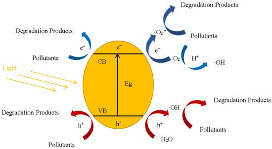
Figure 1.
The schematic mechanism for the photocatalytic behavior of a photocatalyst.
2.2. The Role of Photocatalysis in the Wastewater Treatment Process
Photocatalytic technology is not used throughout the entire wastewater treatment process, so it is necessary to clearly identify the application scenarios of photocatalytic technology in the overall wastewater treatment process and make corresponding designs for PWTRs. Wastewater treatment processes are generally classified into primary treatment, secondary treatment, and tertiary treatment [24]. Primary treatment typically involves the use of physical methods such as precipitation, filtration, air flotation, and centrifugation to remove the larger particles, solids, and grease that float on the surface of wastewater. After primary treatment, the Chemical Oxygen Demand (COD) removal rate in wastewater is approximately 20% [25]. In secondary treatment, both chemical and biological methods are commonly used to treat colloidal and dissolved organic matter in wastewater [26]. The commonly used technologies in this stage include activated sludge, anaerobic treatment, flocculation, etc. [27,28,29]. The COD removal rate in wastewater can be more than 90% after this process [30]. The tertiary treatment targets the removal of nitrogen, phosphorus, and other soluble organic matter that is difficult to treat. Commonly used technologies in this stage include biological denitrification, reverse osmosis, ion exchange, etc. [31]. The combination of photocatalytic mechanisms with wastewater treatment processes reveals that photocatalysts are primarily used in secondary and tertiary treatment. Although biological and chemical methods used in secondary treatment are efficient, they have some drawbacks in practice, such as causing secondary pollution and complex reaction conditions [32]. Photocatalytic technology can alleviate these challenges effectively. Additionally, photocatalytic technology is effective in treating some special wastewater, such as pharmaceutical wastewater, microbial wastewater, heavy metal wastewater, and others [22]. However, the low photocatalytic efficiency of photocatalysis under sunlight and the high cost of electricity under artificial sunlight sources limit its application in the industry [33,34]. To promote the industrial application of photocatalysis, efficient and stable photocatalysts and PWTRs with excellent performance are essential.
3. Factors to Be Considered in the Design of PWTRs
In addition to momentum transfer, heat transfer, and mass transfer, the design of PWTRs also needs to consider photon transfer [35]. The design of photocatalytic reaction spans multiple fields such as chemistry, mechanics, and optics, which undoubtedly increases its design complexity. To address this issue, we discuss the design of PWTRs from various perspectives, including the selection of photocatalysts, the loading form and amount of photocatalysts, the recovery of photocatalysts, the design of light source modules, and reaction condition control.
3.1. The Selection of Photocatalysts
Photocatalysts are key substances used in PWTRs to treat pollutants, which can be divided into two main categories: homogeneous photocatalysts and heterogeneous photocatalysts [36]. Homogeneous photocatalysts have advantages in terms of high reaction rates, fewer side reactions, and mild reaction conditions. However, because homogeneous photocatalysts and reactants are in the same phase, it is challenging to separate the photocatalyst from the pollutants after the reaction, which is not conducive to the recovery and reuse of the photocatalyst [37]. Compared to homogeneous photocatalysts, heterogeneous photocatalysts have a higher mineralization rate and lower reaction rate, which reduces the risk of harmful intermediates accumulating in water [36]. Additionally, heterogeneous photocatalysts are easy to recover and have mature research, making them commonly used in wastewater treatment [38]. Multiphase photocatalysts can be categorized into different types based on their chemical compositions, which include metal oxides, metal sulfides, metal halides, metal–organic frameworks (MOFs), and carbon materials. Different types of photocatalytic materials usually exhibit different effects on different pollutants [39]. Therefore, for practical applications, optimization design and operation should be conducted based on the pollutant types and water environments to achieve better treatment results.
In accordance with the industrial application demands, an excellent photocatalyst should possess low cost, high stability, high activity, and easy recovery [16,34]. Presently, the research on photocatalysts mainly focuses on the following areas: (1) promoting electron–hole separation and reducing recombination [40]; (2) increasing the surface area of photocatalysts to improve the adsorption ability of photocatalysts towards pollutants [41]; and (3) enhancing the recyclability of photocatalysts [42,43]. Additionally, reducing the band gap of photocatalysts to enhance their response to visible light is an important research direction. However, the introduction of certain dopants to broaden their response range to visible light may decrease the photodegradation efficiency of pollutants, which is undesirable for practical applications [44,45]. Through the comparison of industrial demand with laboratory research direction, it is revealed that laboratory research on photocatalysts tends to ignore the control of preparation costs, which causes many photocatalysts with impressive laboratory results to be inapplicable in industrial applications. As a result, photocatalysts with high preparation costs, such as photocatalysts doped with precious metals [46], photocatalysts doped with rare elements [47], and photocatalysts with a complex preparation process [48], are not viable alternatives for industrial applications. Additionally, photocatalysts with poor stability or that cause water pollution, such as CdS, C3N4, SnO2, etc., will be limited in industrial applications as well [2]. The stability of photocatalysts can be characterized using X-ray diffraction (XRD), Fourier-transform infrared spectroscopy (FT-IR), and X-ray photoelectron spectroscopy (XPS) techniques. XRD provides information on the stability of the structure by analyzing the crystal lattice of the material. FT-IR provides insights into the functional groups and molecules of the material to understand its structure and stability. XPS analyzes the electronic structure and chemical state of the surface of the material, which can offer information about the catalytic reaction mechanism and the stability of the photocatalyst’s structure. Combining these techniques provides a more comprehensive understanding of the stability of the photocatalyst’s structure.
Numerous studies have demonstrated that photocatalytic technology is effective in the treatment of compounds [49], antibiotics [50], pesticides [51], heavy metals [52], etc., but the performance of photocatalysts varies depending on the types of pollutant [12]. Therefore, selecting appropriate photocatalysts for different types of pollutants is necessary for efficient wastewater purification. Additionally, the requirements for photocatalytic performance may differ depending on the light source used in industrial applications. There are currently two categories of light sources used in industry: sunlight sources and artificial sunlight sources [53,54]. In the case of sunlight sources, since the UV content of sunlight is only about 5–7%, the selected photocatalyst must respond to visible light in order to facilitate the utilization of sunlight [55]. Benefitting from the advancement of LED technology, LEDs have gradually replaced mercury lamps as the primary artificial sunlight sources in photocatalytic industrial applications [56]. As LEDs have the unique feature of controllable wavelength, the most efficient wavelength can be selected based on the specific properties of the chosen photocatalyst [57,58]. Therefore, under artificial sunlight sources conditions, high activity at specific wavelengths of the photocatalysts is very important. Throughout the 30 years of rapid development of photocatalytic water treatment, a large number of new photocatalysts have been reported. As mentioned above, the choice of photocatalyst should be different in different application scenarios, but this is not the case. In order to identify the most suitable photocatalyst for industrial applications, a statistical analysis of the photocatalysts used from 1991 to 2021 was conducted and is presented in Table 1. Interestingly, although the types of pollutants, the light sources, and the amount of wastewater treated differed in these 25 cases, 23 of the cases (accounting for 92% of the total number of cases) used TiO2-based photocatalysts. Moreover, of the 23 cases using TiO2-based photocatalysts, 18 cases used P25 or TiO2, and 3 cases used TiO2/H2O2 or TiO2/O3. A large number of new photocatalysts reported in the literature do not seem to be used in industry. This phenomenon can be attributed to several reasons. Firstly, research on TiO2-based photocatalysis is relatively more mature, and the costs are relatively low in comparison to new photocatalysts, making it more suitable for industrial applications. Secondly, while many new photocatalysts show superior performance in specific aspects, these breakthroughs are not enough to replace the status of TiO2-based photocatalysts. Therefore, based on factors such as stability, photocatalytic efficiency, and cost, TiO2-based photocatalysts may still be the mainstream for industrial applications.

Table 1.
Photocatalysts used in industrial use cases.
3.2. Loading Forms and Amount of Photocatalyst in PWTRs
When the photocatalyst is determined, the loading forms of the photocatalyst should be considered in the PWTR. Two types of PWTR systems can be identified based on the loading form of the photocatalyst: slurry PWTRs and immobilized PWTRs. Slurry PWTRs are known for their high reaction rates and efficiency, as the photocatalysts are mixed in the wastewater to achieve full contact with the pollutants. However, they presents challenges for photocatalyst separation and recovery [84]. On the other hand, immobilized PWTRs allow for a continuous reaction and easy recycling of the photocatalyst. However, the immobilization of the photocatalyst can reduce the total irradiation area and the contact area between the photocatalyst and the contaminant [85], which are crucial factors affecting photocatalytic efficiency [86]. Consequently, the photocatalytic efficiency of immobilized PWTRs is often lower than that of slurry PWTRs due to reduced irradiation and contact areas. In the following section, we will discuss these two types of reactors in detail.
3.2.1. Slurry PWTRs
Annular reactors are a common type of slurry PWTR, as shown in Figure 2A [87]. Such a reactor is composed of a tubular reactor with a central irradiated light source, oxygen inlet, lamp heat dissipation device, aeration device, etc. However, this kind of photocatalytic reactor has some shortcomings. Firstly, due to the effects of gravity, the photocatalyst and some pollutants tend to deposit at the bottom of the reactor, resulting in the concentration at the bottom of the reactor being higher than the concentration at the top [88]. Meanwhile, the distribution of the light source in the reactor is relatively uniform. The uneven distribution of photocatalyst-pollutants and the uniform distribution of the light source lead to a decrease in photon utilization and affect the overall photocatalytic efficiency. Secondly, the light source is located at the central axis of the tubular reactor, and the backlight surface of the photocatalyst cannot absorb photons to carry out the photocatalytic reaction, thus reducing the overall photocatalytic efficiency. These problems can be addressed by the implementation of appropriate solutions. For instance, magnetic stirring, steam stripping, and impeller stirring can be employed to address the gradient concentration issue [89], while the use of multiple light sources can mitigate the uneven illumination problem [90,91]. Additionally, the flow photocatalytic reactor is a viable solution to improve the mass transfer efficiency and energy efficiency of the slurry PWTR. Wan-Kuen et al. developed a spiral photocatalytic reactor, as shown in Figure 2B, which consists of a spiral tube and a cylindrical light source. The cylindrical light source, located at the center of a spiral tube, uses blue LEDs, and the photocatalyst used is TiO2. This reactor was applied for the degradation of malachite green (MG) dye. Due to the adsorption of MG dye on TiO2, the spectral response of TiO2 was extended to the visible region (449 nm), which significantly improves the degradation efficiency of MG dye by TiO2 under blue LED irradiation. This study also compared the degradation efficiency of MG dye under both UV-LED and blue LED irradiation. Although the photocatalytic performance was slightly lower under blue LED irradiation compared to UV-LED irradiation, the lower energy consumption and cost of blue LED make it a more economically viable option [92]. In order to further improve the control system of reaction conditions of photocatalytic reactors, Le et al. developed an integrated photocatalytic liquid-phase reactor. The photocatalytic reactor integrates temperature control, stirring, light source power regulation, and other functions and is controlled by a piece of Raspberry Pi. The reactor can effectively control the main environmental factors which affect the photocatalytic reaction rate, leading to improved photocatalytic efficiency [93]. Although the slurry photocatalytic reactor has high photocatalytic efficiency, recovering the photocatalyst in the slurry system poses a challenge. Therefore, an independent photocatalyst recovery module is needed for the slurry photocatalytic reactor, which will be discussed in Section 3.3.
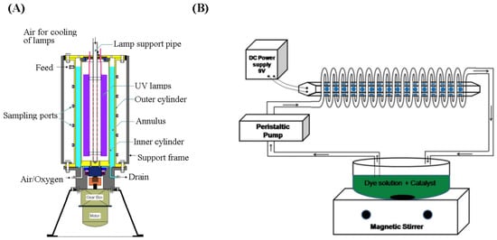
Figure 2.
(A) Schematic of toroidal reactor setup [87], Copyright 2010, Springer. (B) Schematic diagram of spiral-shaped photocatalytic reactor setup [92], Copyright 2015, Wiley.
3.2.2. Immobilized PWTRs
Compared to slurry PWTRs, the significant advantage of immobilized PWTRs is the elimination of the need to design a separate catalyst recovery device, while preventing photocatalyst agglomeration and deactivation [94]. Based on various carriers, immobilized reactors are classified into circular reactors [95], optofluidic microreactors [96], capillary array reactors [97], fiber optic reactors [98], foam reactors [99], etc., as shown in Figure 3. Figure 3a shows a parallel plate photocatalytic reactor in which the photocatalyst is loaded onto the inner wall of a circular parallel plate. Due to the flat design of the reactor, light can easily pass through the reaction liquid, resulting in a high photocatalytic rate. However, this type of reactor exhibits a low photocatalytic surface area, limiting the number of photocatalysts the reactor can carry, affecting the further improvement of photocatalytic efficiency. Figure 3b shows an optofluidic microreactor in which the photocatalyst is loaded into the flow channel. Due to the microfluidic form, this type of reactor not only has a higher photocatalytic surface area and higher mass transfer efficiency but also does not require the addition of a stirring device. However, such reactors are more suitable for reactions with faster reaction rates rather than for reactions with longer reaction times. Figure 3c shows a microcapillary reactor, which loads the photocatalyst onto the microcapillary. This type of reactor also possesses a high photocatalytic surface area, which effectively enhances the photocatalyst loading capacity. Nevertheless, similarly to optical microreactors, this reactor is vulnerable to clogging from fine solid particles in the reaction solution. Figure 3d shows a foam photocatalytic reactor and its preparation. The photocatalyst is loaded onto nickel foam. The irregular surface of nickel foam effectively increases the loading of the photocatalyst. Additionally, the high hydrophilicity and the low reaction fluid viscosity of nickel foam contribute to the increase in photocatalytic rate. Figure 3e shows a fiber optic reactor and the optical path inside the fiber. The photocatalyst is loaded outside the fiber. The reactor not only has a high photocatalytic surface area but also effectively improves the utilization rate of the light source.
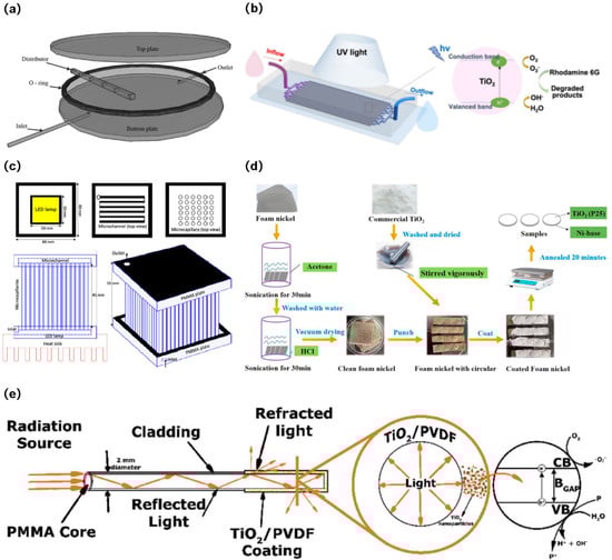
Figure 3.
(a) Exploded view of the circular reactor [95], Copyright 2015, Elsevier. (b) Optofluidic microreactor for photocatalytic water purification [96], Copyright 2022, Springer. (c) Schematic of microcapillary photoreactor setup [97], Copyright 2022, Elsevier. (d) Flowchart for the preparation process of foam reactors [99], Copyright 2021, Elsevier. (e) Schematic representation of the application of polymeric optical fibers (POF) in the photocatalytic treatment of turbid water fiber optic reactors [98], Copyright 2018, Wiley.
Since the immobilized reactor effectively addresses the issue of photocatalyst recovery, research primarily focuses on improving photocatalytic efficiency. M. Vezzoli et al. designed a parallel plate reactor, as shown in Figure 4, with a light source consisting of seven mercury lamps of 15 W power. The TiO2 film was loaded onto the inner wall of the reactor and was used to investigate the effect of reaction parameters on the degradation rate of phenol. It was found that the photocatalytic efficiency was improved by increasing the thickness of the photocatalytic film; however, when the thickness increased to a certain level, the photocatalytic efficiency could not be further improved [100]. A possible reason for this phenomenon is that the low photocatalytic surface area of the reactor results in a limited contact area between the photocatalyst and pollutants and light, so even if the photocatalyst load is further increased, the photocatalytic efficiency cannot be improved. Therefore, the improvement of photocatalytic efficiency of the immobilized reactor can be considered from the following two points: one is to increase the photocatalytic surface area of the photocatalytic reactor [101], and the other is to provide the photocatalyst with an irradiation intensity that matches the amount of photocatalyst and improve the light source utilization rate of the reactor [102].
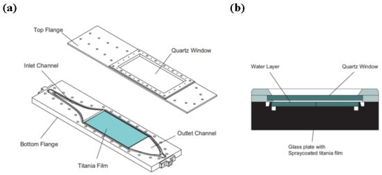
Figure 4.
Reactor geometry. (a) Exploded view of top and bottom flange; (b) cross section of the reactive area [100], Copyright 2011, Elsevier.
In order to increase the photocatalytic surface area of the immobilized reactor, Li et al. developed two photoelectrodes with different structures and applied them to rotary disc photocatalytic reactors. Two photoelectrodes with different surface structures are shown in Figure 5, where Figure 5a,b are the top and side views of the wedge surface disk electrodes, respectively, and Figure 5c is the top view of the pyramid surface disk electrode. Both surface structures have good degradation effects on dye wastewater, and the degradation rate of the wedge surface structure on dye wastewater is slightly higher than that of the pyramid surface structure. The wedge surface of the reactor provides a larger surface area, facilitating multiple reflections of radiation light on its surface to improve the light utilization efficiency. Additionally, the increased surface area allows the electrode to carry more pollutants for treatment [103]. The microphotocatalytic reactor is another feasible solution due to its high photocatalytic surface area and low energy consumption [104,105]. A capillary array photocatalytic reactor (CAPCR) has been developed by Zhang et al., as shown in Figure 6. The capillary array photocatalytic reactor consists of a lamp source in the middle (the number 2 in Figure 6) and a capillary array coated with P25 photocatalyst around it (the number 1 in Figure 6). The tube had an inner diameter of 320 µm and a volume of 0.012 mL, and the reactor was illuminated with an 11 W mercury lamp. The results show that the capillary array photocatalytic reactor has a higher photocatalytic surface area, which increases the contact area between pollutants and photocatalyst, and thus has higher azo dye degradation efficiency than the conventional intermittent reactor [106]. However, the large number of gaps between the capillary arrays leads to much of the light overflowing through these gaps, resulting in low utilization of this reactor’s light source. Additionally, the TiO2 coating on the fiber has many areas that cannot be illuminated by light sources, which also affects the utilization of the light source.
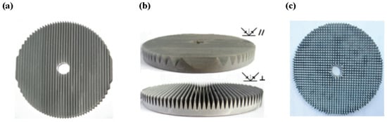
Figure 5.
(a) Top view of the wedge surface disk electrode; (b) side view of the wedge surface disk electrode; (c) top view of the pyramid surface disk electrode [103], Copyright 2011, American Chemical Society.
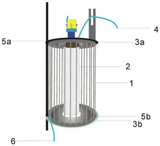
Figure 6.
The schematic diagram of capillary array photocatalytic reactor (CAPCR) structure. 1: capillary with TiO2 film; 2: UV lamp; 3a and 3b: up and down brackets; 4: outlet; 5a and 5b: up and down tetrafluoroethylene tubes; 6: inlet [106], Copyright 2012, Elsevier.
Some studies showed that the combination of multiple microreactors into a larger structure is effective for improving the light source utilization of PWTRs. Zhang et al. designed a capillary microphotoreactor packed with TiO2-coated glass beads. They filled glass beads with a photocatalyst coating layer in capillaries; the structure is shown in Figure 7. At the same time, Figure 7 also shows the microstructure of glass beads with photocatalyst coating and the photocatalytic efficiency of this capillary microphotoreactor compared to the conventional membrane photocatalytic reactors (MPRs) [107]. It was found that nearly 100% degradation efficiency could be achieved in an 80# glass bead packed MPR within 20 s, which was more than two orders of magnitude higher than the value obtained in a wall-coated MPR under the same operational conditions. There were three main reasons for this: Firstly, the combination of multiple microreactors increased the number of boundaries inside the reactor, creating more scattering and reducing the loss of energy. Secondly, it increased the photocatalytic surface area of the whole system, which was expected to improve the performance of the reactor. Thirdly, it improved the flow distribution as well as the mass transfer from the body to the surface [108]. So, this approach can further improve the loading amount of the photocatalyst as well as the utilization of light [109,110].
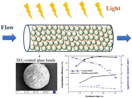
Figure 7.
Capillary microphotoreactor packed with TiO2-coated glass beads and a comparison of the photocatalytic efficiency of this reactor with a conventional MPR (membrane photocatalytic reactor) [107], Copyright 2020, Elsevier.
3.2.3. Loading Amount of Photocatalyst
Once the loading forms of the photocatalyst have been determined, it is important to determine the appropriate loading amount of photocatalyst, in order to enhance photocatalytic efficiency and avoid the waste of photocatalyst [111]. In both the immobilized PWTRs and slurry PWTRs, the photocatalyst loading will directly affect the photocatalytic reaction rate. Most studies show that the photocatalytic reaction rate is positively correlated with the photocatalyst dosage [112]. However, as the photocatalyst dosage reaches an extreme value, the photocatalytic reaction rate will not be enhanced by continuing to increase the photocatalyst dosage [113,114]. This extreme value is directly related to the structure of the PWTR and the reaction conditions. In principle, the photocatalytic efficiency depends on the number of photocatalysts irradiated by the effective wavelengths; the more photocatalysts irradiated by the effective wavelengths (the effective wavelengths are the wavelengths that can excite the photocatalyst), the faster the photocatalytic reaction rate [2]. In some studies, it was found that an excessive increase in photocatalyst loading led to a decrease in reaction rate. For example, Ashouri et al. investigated the effect of ZnO-based nanophotocatalysts on the degradation of aniline, where three concentrations of 0.5 g/L, 1 g/L, and 1.5 g/L were used for the degradation of aniline in their experiments. It was shown that the degradation rate of aniline increased when the amount of nanophotocatalyst was increased from 0.5 g/L to 1 g/L but decreased when the amount was further increased to 1.5 g/L. This may be the excessive addition of the catalyst bringing about the turbid solution; meanwhile, the penetration depth of UV light is limited, which results in a decrease in the number of photocatalysts illuminated by the effective wavelength [115]. Although the excessive load of photocatalyst in the immobilized photocatalytic reactor may not result in a significant decrease in photocatalytic rate, as seen in the slurry photocatalytic reactors, it is still necessary to control the amount of photocatalyst to avoid waste [116]. Badri et al. investigated the effect of loading amount of photocatalyst on photocatalytic efficiency in an immobilized photocatalytic reactor and found that for a 100 mL solution with 0.02 g/L methyl red (MR), the degradation of MR after 60 min was about 79% at a catalyst loading of 1 g/L. After increasing the catalyst loading to 2 g/L, the degradation rate of MR was 89% in the same reaction conditions. At catalyst loadings of 3, 4, and 5 g/L, degradation rates of MR were observed to be 98%, 99%, and 100%, respectively. No significant increase in the reaction rate was observed when the catalyst loading exceeded 5 g/L. Therefore, for the degradation of the prepared 100 mL solution with 0.02 g/L MR, and the optimum catalyst loading was 3 g/L, since there was no significant increase in MR degradation rate beyond this loading [117].
Based on the above discussion, it is not difficult to find that the loading forms of photocatalysts and the amount of photocatalysts irradiated by the effective wavelength are the main factors affecting the photocatalytic reaction rate. Therefore, in the design of PWTRs, it is necessary to select a reasonable loading form according to the actual situation and to optimize the reactor structure according to the selected loading form, so as to maximize the effective loading amount of photocatalyst and promote the improvement of photocatalytic efficiency.
3.3. Summary of Photocatalyst Recovery and Reuse Module
Reusability of photocatalysts is a major advantage of photocatalytic wastewater treatment technology, so it is necessary to design a photocatalyst recovery module in the reactor, especially for slurry PWTRs. The most widely used methods to recover photocatalysts in PWTRs include the precipitation method, filtration method, and magnetic recovery method. Different recovery methods also correspond to different recovery modules [118,119]. The precipitation method is the simplest. Woori et al. used a gel-sol method and thermal annealing to synthesize sub-micrometer-sized TiO2 particles, which showed comparable activity to commercialized P25. Interestingly, due to the large size of this photocatalyst, it can naturally precipitate to the bottom of the reaction solution after a short period of standing and can be easily separated from the reaction solution, as shown in Figure 8a. They uniformly dispersed 50 mg of sub-micro photocatalyst (550-TiO2) and 50 mg of P25 in 100 mL of water and then compared the sedimentation effect of the two photocatalysts after standing for 5 min. It is obvious that the sedimentation effect of 550-TiO2 is much better than that of P25 [44]. Different from the precipitation method, the filtration method requires the design of a filtration device that matches the particle size of the photocatalyst. Benotti et al. designed a tubular reactor with a photocatalyst recovery device, which is shown in Figure 8b, the arrows in the figure indicate the flow path of wastewater in the reactor [71]. The recovery unit consists of a bag filter with a pore size of 10 µm (which shown in Figure 8b-8), and after the reaction, the photocatalyst is separated from the wastewater through the recovery unit. Magnetic force recycling is another popular technique used to recover photocatalysts. Fu et al. prepared a magnetic BiOI/rGO/Fe3O4 composite photocatalyst using the hydrothermal method which can be recovered by an external magnetic field. The experiment also showed that the degradation rate of rhodamine B (RhB) can still reach 82% after 10 cycles, indicating that the magnetic composite photocatalyst has good recyclability [45]. Moreover, combining multiple recycling technologies can also have a favorable recovery effect. Li et al. developed a submerged magnetic separation membrane photocatalytic reactor, as shown in Figure 8c. The reactor uses TiO2-Fe3O4 as a photocatalyst, which not only enhances the multiphase photo-Fenton degradation of organic compounds but also realizes the separation of photocatalysts by magnets. The reactor is fitted with a low-pressure mercury lamp, a perforated aeration tube, a hollow ceramic membrane, and an iron rod connected to an external magnet. The red and green arrows in the figure indicate the path of gas transport from the air compressor to the reactor, and the black arrow indicates the direction of wastewater flow. Before the reaction, the reaction liquid is pumped into the reactor through a peristaltic pump. During the reaction, the low-pressure mercury lamp and the aeration device are turned on to promote the treatment of the catalyst to the pollutants. After the reaction, the ceramic membrane inside the reactor is used to separate the photocatalyst from the reaction liquid, and finally, the catalyst is recovered by connecting an iron rod to an external magnet [120].
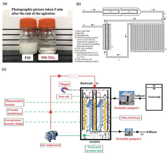
Figure 8.
(a) Comparison of P25 and 550-TiO2 precipitation effect [44], Copyright 2021, Elsevier. (b) General schematic of photocatalytic tubular reactor with catalyst recovery device [71], Copyright 2009, Elsevier. (c) Schematic illustration of the submerged magnetic separation membrane photocatalytic reactor (SMSMPR) [120], Copyright 2019, Royal Society of Chemistry.
Immobilized PWTRs effectively solve the problem of photocatalyst recovery in wastewater treatment, but the replacement of photocatalysts is still a crucial consideration [121]. After several reaction cycles, the photocatalytic performance of the photocatalyst will decrease due to the influence of pollutant adsorption and other factors [122], so it is necessary to replace the photocatalyst. In order to facilitate the replacement of the photocatalyst, the carrier for loading photocatalysts should be easily replaceable. Destaillats et al. designed a multi-plate photocatalytic reactor which is shown in Figure 9, consisting of several parallel and equidistantly spaced aluminum plates coated with titanium dioxide films. The light source passes vertically through these plates [123]. The photocatalytic reactor adopts a modular design, allowing the aluminum plate to be easily separated from the reactor’s body. Therefore, when the photocatalyst activity is reduced or inactivated, only the aluminum plate coated with the photocatalyst needs to be replaced to achieve photocatalyst replacement.
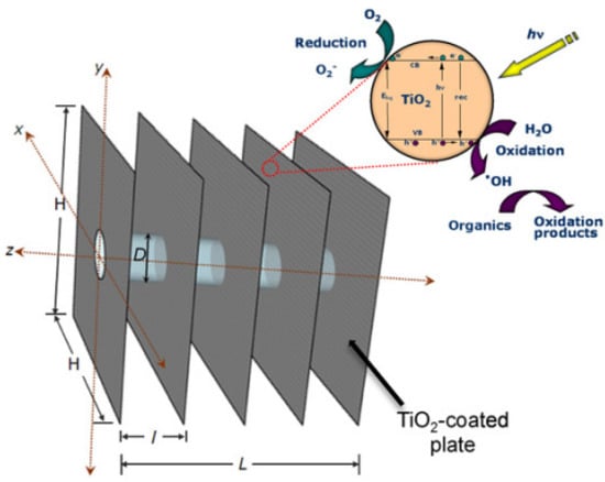
Figure 9.
Multi-plate photocatalytic reactor with one lamp [123], Copyright 2013, Elsevier.
3.4. Design of Light Source Modules
3.4.1. The Type of Light Source
Solar
The light source module plays a crucial role in the design of PWTRs and requires more attention. According to the different types of light sources, PWTRs can be divided into two types: solar PWTRs [53] and artificial sunlight source PWTRs [54]. Solar reactors use sunlight as the light source. However, since the ultraviolet content of sunlight is only 5–7%, solar reactors often require a concentrator-visible photocatalyst to improve photocatalytic efficiency [124,125]. The use of a concentrator can not only effectively improve the irradiation intensity of sunlight in the reactor but also increase the temperature in the reactor. The synergistic effect of photo-thermal excitation can effectively promote the enhancement of the photocatalytic reaction process [126]. Solar reactors can be divided into two main categories: concentrating reactors and non-concentrating reactors. Concentrating reactors are further divided into parabolic trouble collector (PTC) reactors and compound parabolic concentrator (CPC) reactors. PTC reactors consist of a concentrator, a sunlight tracking device, and a reactor. Light collectors usually include parabolic troughs or parabolic surfaces which can concentrate sunlight in a line or a point, thereby exciting the photocatalyst to treat the pollutant. The PTC reactor’s structure and light pathways are presented in Figure 10a [127]. PTCs can increase the intensity of sunlight by tens or even hundreds of times, thus significantly increasing the photocatalytic rate. At the same time, this type of reactor has the advantage of small size and high mass transfer efficiency. However, they have some drawbacks. Firstly, PTCs can only utilize direct UV radiation and cannot utilize scattered light, resulting in a lower utilization rate of ultraviolet light. Secondly, although high intensity radiation accelerates the removal of pollutants, it also leads to system overheating, thus accelerating pipeline leakage and corrosion. Finally, the solar tracking device in the PTC system has a complex structure and high production cost, making it difficult to promote [128]. The CPC reactor has no sunlight tracking device and collects sunlight only through two fixed parabolic slots, the structure of which is shown in Figure 10b. Due to its special geometry, the CPC reactor can collect light in almost all directions, which improves the utilization of sunlight and reduces the manufacturing cost of solar reactors at the same time [129]. Therefore, CPC is considered to be the most promising solar photocatalytic reactor and is the most widely used in industry [113]. Non-concentrating reactors usually consist of a fixed device placed at an inclination, as shown in Figure 10c, and the inclination angle of the reactor depends on the local solar incidence angle [130]. Non-concentrating reactors can effectively utilize both direct and reflected light, so they have better results in cloudy or humid environments [131].
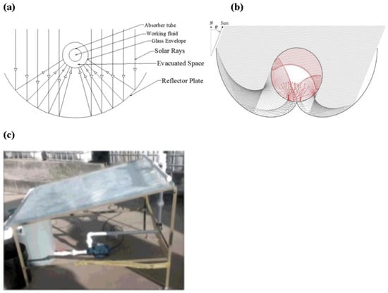
Figure 10.
(a) The structure of a PTC reactor [127], Copyright 2016, Elsevier. (b) The structure of a CPC reactor [129], Copyright 2017, Elsevier. (c) The structure of a non-concentrating reactor [130], Copyright 2017, Elsevier.
Artificial Sunlight Sources
Artificial sunlight sources, such as mercury lamps and LEDs, are commonly used in photocatalytic reactions due to their controllable wavelength characteristics. These light sources are beneficial to UV photocatalysts because they can provide a suitable wavelength according to the characteristics of the photocatalyst, leading to the effective improvement of photocatalytic efficiency [132]. It is estimated that the overall energy efficiency of converting natural light into hydroxyl radicals to destroy pollutants is only 0.0005–0.4%, while the overall energy efficiency is 0.0002–2% when UV light is used [133]. Therefore, from the perspective of photocatalytic efficiency and energy efficiency, the use of artificial sunlight sources is more advantageous. Mercury lamps are a common light source for photocatalysis at present, and the low cost and better light source distribution of mercury lamps are the major advantages. However, the wavelength of mercury lamps is not concentrated, which means that the mercury lamp may produce many wavelengths that cannot excite the photocatalyst, resulting in a waste of resources. Moreover, mercury lamps also have the defects of environmental pollution, short life span, and so on [56]. Compared with mercury lamps, LEDs have the advantages of lower energy consumption and more stable and concentrated wavelengths [57,58], which makes the photocatalytic reaction much more efficient in terms of photon utilization [134,135]. Therefore, an LED light source seems to be more suitable for application in PWTRs [54]. In recent years, with the development of semiconductor technology, the luminous efficiency of LEDs has gradually improved, and the production cost has dropped rapidly. Furthermore, with the implementation of the national energy conservation and emission reduction policy [136], it will be a major trend to replace mercury lamps with LEDs in the future.
3.4.2. The Wavelength of the Light Source
In the terms of light source, there are three main factors affecting photocatalytic efficiency: wavelength, irradiation intensity, and irradiation uniformity [137]. According to the photocatalytic mechanism, only photons with sufficient energy can initiate a photocatalytic reaction, and the higher the energy of the photon, the shorter the wavelength of the light source. Therefore, the wavelength of the light source determines whether the photocatalytic reaction can occur. However, a shorter wavelength is not always better. Generally, after being absorbed, light energy can excite the electrons of a catalyst to its first excited state (S0→S1). In this case, the energy level structure of the catalyst is altered, producing an excited, high-energy electron, which increases the probability of an effective reaction with reactants. Therefore, compared to a catalyst in a ground state, a catalyst in an excited state is more favorable for promoting photocatalytic reactions. However, if the light wavelength is too short, the excitation level of the catalyst will not be S0→S1 but S0→Sn (n > 1), leading to a decrease in reaction efficiency. Therefore, in practical applications, it is important to choose an appropriate wavelength to enhance the efficiency of photocatalytic reactions [138]. Li et al. indicated that the removal rates of sulfadiazine and sulfamethoxazole by TiO2 were different at different wavelengths, where 365 nm > 254 nm > 420 nm > 475 nm. The low photocatalytic efficiency of TiO2 under illumination at 420 nm and 475 nm is caused by the weak absorption of 420 nm and 475 nm light by TiO2. The penetration ability of 254 nm is poor and cannot be effectively transmitted in a solution with poor light transmission, leading to lower photocatalytic efficiency than that of 365 nm [139]. However, the use of a xenon lamp and bandpass filters to obtain a single-wavelength light source in this experiment resulted in differing irradiance levels for each wavelength. The measured light intensities for the radiation conditions of 254, 365, 420, and 475 nm were 148 ± 2, 123 ± 1, 42 ± 0.5, and 35 ± 1 mW/cm2, respectively, which may have had some impact on the experimental outcomes. In a separate study conducted by Eskandarian et al., the effects of different wavelengths on the photocatalytic degradation of acetaminophen, diclofenac, ibuprofen, and sulfamethoxazole were investigated using UVC (365 nm)/UVB (300 nm)/UVA (250 nm) LEDs and TiO2. The light power of each of the three wavelength LEDs was 10 mW. The findings revealed that UV wavelength was a more vital parameter for the decomposition than light intensity. Shorter wavelength UV is more effective in the decomposition of the pharmaceuticals [140]. In addition, the manufacturing and energy consumption costs of PWTRs need to be considered. Martín-Sómer et al. showed that LEDs with emission peaks at 365, 385, 390, 395, 400, and 405 nm produced 3.75, 4.87, 4.95, 5.54, 5.92, and 6.78 E/kWh of photons, respectively, at the same energy consumption (where E/kWh is moles of photons per unit of electrical power) [141], as shown in Figure 11, which means that LEDs with shorter wavelengths need to consume more energy to produce the same number of photons compared to LEDs with longer wavelengths and that LEDs with shorter wavelengths will have a higher manufacturing cost [58]. Therefore, when low-wavelength LEDs are selected as the light source for PWTRs, both the manufacturing cost and the operating cost of the reactor will increase. When designing light sources for PWTRs, a compromise among energy consumption, manufacturing cost, and photocatalytic efficiency must be explored.
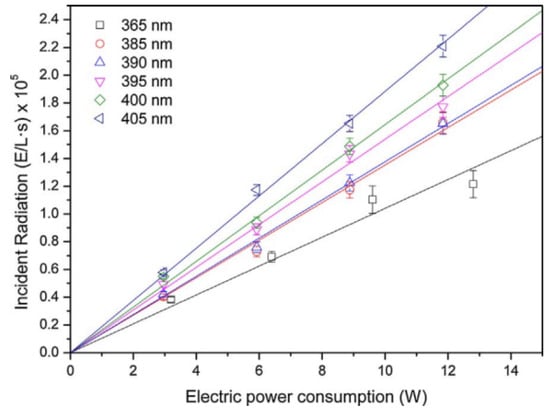
Figure 11.
The relationship between incident radiation and power consumption of LED light sources of different wavelengths [141], Copyright 2018, Elsevier.
3.4.3. The Irradiation Intensity of the Light Source
Irradiation intensity also affects the photocatalytic rate, so an appropriate increase in irradiation intensity can effectively increase the photocatalytic rate. The effect of irradiation intensity on the reaction rate constant (k) was investigated by Wen et al. [142]. It was shown that the k value increased from 0.091 to 0.203 h−1 when the UV light intensity was increased from 0.143 to 0.510 mW/cm2, which is shown in Figure 12. The reason is that more irradiation intensity excites more photons and promotes the interaction between the photocatalyst and photons, which results in more electron–hole pairs. However, further increasing the irradiation intensity does not increase the k value, which may be due to the saturation of photogenerated electron–hole pairs and excessive irradiation intensity accelerating the recombination of electron–hole pairs [143]. In addition, high radiation intensity of light may induce a multiexciton effect, leading to excited annihilation and lower photogenerated electron–hole pairs. This could ultimately reduce the photocatalytic activity. Therefore, it is important to regulate the radiation intensity of light for optimal performance [144]. Ollis summarized the effect of light intensity on photocatalytic kinetics and confirmed that the photocatalysis rate increased linearly with light intensity in the low range, depended on the square root of light intensity in the moderate range, and was independent of light intensity in the high range [145]. In addition, although the irradiation intensity of the LED will increase with the increase in the current, this relationship is not linear because at high current intensity, the efficiency of the LED will decrease. This means that high light intensity will lead to reduced energy utilization of LEDs [56]. At the same time, too high light intensity will also cause the LED to generate more heat, which will significantly affect the LED’s life. Therefore, from the perspective of energy consumption, it may be more economical to increase the number of LEDs to increase the irradiation intensity instead of increasing the current of the LED [146].
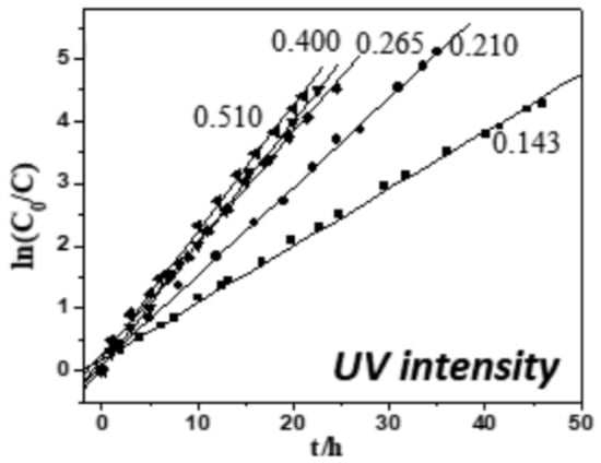
Figure 12.
Effect of light intensity on reaction rate constants [142], Copyright 2018, Elsevier.
3.4.4. The Uniformity of the Light Source
The irradiation uniformity also has a great influence on photocatalytic efficiency. Martín-Sómer et al. compared three different UVA light sources (a mercury fluorescent lamp, an 8-LED-based system and a 40-LED-based system) with different light distributions, as shown in Figure 13. Their findings showed that 40-LED-based systems had better photocatalytic rates than 8-LED-based systems at the same energy consumption due to their superior irradiation uniformity [56]. It was proved that the efficiency of photocatalysis can be improved by increasing the number of LEDs and optimizing the distribution structure. Deba et al. used photocatalytic ceramic membranes to explore the effect of irradiation uniformity on photocatalytic effect, and they found that more uniform irradiation increased the degradation rate of MB from 35% to 55% compared with non-uniform irradiation [147]. Therefore, it is necessary to design the light source distribution in the reactor to make the light distribution inside the reactor as uniform as possible, thus improving the photocatalytic efficiency of the PWTR [148].
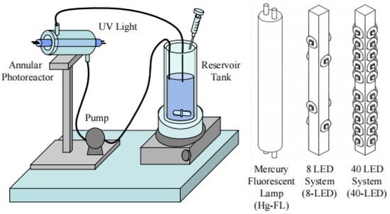
Figure 13.
Schematic representation of an experimental setup used to explore the influence of light distribution on photocatalytic efficiency [56], Copyright 2017, Elsevier.
3.5. Summary of Reaction Condition Control Module
In addition to photocatalysts and light sources, other reaction conditions, such as flow rate, temperature, dissolved oxygen, pH, types of pollutants, etc., also affect the photocatalytic efficiency. Therefore, when designing the PWTR, it is essential to design corresponding adjustment modules to control the reaction conditions so that the photocatalytic reaction can be carried out under appropriate reaction conditions so that the photocatalytic efficiency can be improved.
3.5.1. Flow Rate
In continuous flow photocatalytic reactors, the flow rate of wastewater is a critical factor that affects the photocatalytic reaction rate. This is because an increase in liquid flow rate enhances the turbulence in the reactor and leads to greater contact between the particle surface and the liquid phase. Additionally, the turbulence can decompose bubbles into smaller bubbles and provide more interface area [149]. Enesca et al. also compared a variety of photocatalytic reactors with different flow rates and found that an optimal flow rate facilitates the re-adsorption of oxygen on the photocatalyst surface, allowing it to react with excess photogenerated electrons, thereby reducing the recombination of electrons and holes [150]. Therefore, in order to control the flow rate in fluid photocatalytic reactors, a peristaltic pump is often used as the feeding device in some applications to regulate the flow rate [92,122]. In practical applications, the relationship between the liquid flow rate and the light source irradiation time also needs to be fully considered because the increase in the flow rate will inevitably lead to the shorter irradiated time of the pollutants on the surface of the photocatalyst. To determine the optimal flow rate for a reaction, computational fluid dynamics (CFDs) simulation is an efficient approach. Cloteaux et al. modeled a fixed-bed photocatalytic reactor for formaldehyde degradation. The model considered hydraulics, light distribution, chemical kinetics, and mass transfer in the reactor, and combined with the Langmuir–Hinshelwood kinetic model, it accurately predicted the change in concentration at the outlet of the reactor under different flow rates [151].
3.5.2. Temperature
Temperature is another important factor that affects photocatalytic efficiency. Murillo-Acevedo et al. designed a photocatalytic reactor and investigated the impact of temperature on the photocatalytic efficiency of the reactor. The results showed that the photocatalytic efficiency increased with the increase in temperature. This may be because the temperature may affect the interface rate of electrons to oxygen, and the recombination rate increases slowly with the increase in temperature, while the holes on the surface oxygen atoms become stable due to the adsorption of water. Moreover, high temperature will accelerate the adsorption rate of pollutants and products, which will lead to the improvement of the availability of surface reaction active centers [152]. Therefore, it is necessary to design a temperature control device to monitor accurately the temperature of the reactor. For temperature control, two aspects should be mainly considered: one is the temperature control of the reaction solution, and the other is the temperature control of the light source. These two factors need to be independent of each other because higher temperature can improve the photocatalytic efficiency of the reaction solution, but for the light source, higher temperature may reduce the electro-optical conversion efficiency of the light source [153].
3.5.3. pH
The pH value affects the adsorption of the reaction species and the size of the photocatalyst aggregates; it is necessary to control the appropriate pH to improve the photocatalytic efficiency [2]. Koe et al. summarized the optimal pH values of different photocatalysts in the reaction [154], as shown in Table 2. It is evident that the optimal pH value is different for different photocatalysts. Therefore, it is very important to design a pH-regulating device to maintain the optimal pH value of the reaction solution. For large photocatalytic reactors with long reaction times, such as pot reactors, an automatic pH adjustment device needs to be designed to control the constant pH of the solution during the reaction. For small rapid-reaction photocatalytic reactors, such as microfluidic reactors, the pH of the solution is often adjusted to the optimal state in a pretreatment module, and then the solution is fed into the reactor.
Table 2.
pH for different types of photocatalysis activities [154].
3.5.4. Dissolved Oxygen
From the perspective of the photocatalysis mechanism, dissolved oxygen is the main substance that generates oxidation active groups, so increasing the dissolved oxygen content in the reaction solution can effectively improve the photocatalytic efficiency. Ye et al. investigated the effect of dissolved oxygen in water on photocatalytic efficiency and showed that the electron–hole complex was effectively prevented because dissolved oxygen could react with photogenerated electrons to form ·O2−. Meanwhile, the formed ·O2− could participate in the degradation of Anthraquinone(AQ) [155]. It can be seen that the photodegradation performance of the photocatalyst increased with the increase in dissolved oxygen concentration, and the high concentration of dissolved oxygen had an obvious promotion effect on the photocatalytic efficiency. Therefore, in the design of PWTRs, aeration devices can be added to regulate the concentration of dissolved oxygen in the wastewater [156].
3.5.5. Composition of Pollutants
Currently, a large amount of research on photocatalytic water treatment is focused on the treatment of a single type of pollutant. However, the types of pollutants in industrial wastewater are complex and diverse. Therefore, to achieve industrial application of photocatalytic wastewater treatment technology, it is necessary to consider the mutual effects between various pollutants during the photocatalytic water treatment process. Firstly, it is important to assess the presence of substances that inhibit photocatalytic reactions in actual wastewater. These substances can be removed using pretreatment techniques to improve photocatalytic efficiency, as discussed in detail in Section 4.1. Secondly, the competitive relationship between different pollutants must be considered, and appropriate reaction conditions should be selected to achieve the optimal treatment effect. Wang et al. examined the competitive relationship of mixtures of three dyes, MB/RhB/MO, under different pH conditions. In a single dye solution, optimal pH values for MB, RhB, and MO were found to be pH = 13.01, pH = 1.06, and pH = 1.06, respectively. When all three dyes were present in a mixture, MO displayed the fastest degradation rate at pH = 6.5, while RhB demonstrated gradual degradation within 300 min before rapidly degrading thereafter. The photocatalytic degradation of MB followed a pseudo-first-order kinetic process. All dyes displayed stable photocatalytic degradation at pH = 1.06, with MB exhibiting a slightly higher degradation rate than MO and RhB. Compared with the first two pH conditions, at pH = 13.01, all three dyes had a good degradation efficiency, with almost complete degradation within 300 min. Therefore, alkaline conditions are undoubtedly more suitable for the degradation of these three dye mixtures in wastewater [157]. Suhaimi et al. also studied the competitive photocatalytic degradation of dyes and found that dyes with planar conformation and smaller size dominate photocatalytic degradation in binary or ternary solutions, based on a comparison of degradation kinetics and diffusion of the dyes [158].
4. Optimization of Photocatalytic PWTRs
4.1. Multi-Technology Coupling
Although photocatalytic technology has many advantages, achieving successful wastewater treatment through the use of a single photocatalytic technology can be impractical. Therefore, the efficiency of wastewater treatment can be improved by coupling photocatalysis with other technologies in the practical application. Technologies such as pretreatment, photocatalysis-membrane, photocatalysis/biodegradation, and sonophotocatalytic technology can be utilized to accomplish this objective.
Pretreatment technology can prevent some substances in the wastewater and inappropriate reaction conditions from inhibiting the photocatalytic efficiency. For example, a filter device can be installed at the reactor water inlet of the reactor to intercept large particles and prevent high turbidity from negatively impacting wastewater photocatalytic efficiency [159]. Similarly, sulfate and chloride ions in the wastewater need to be treated before the wastewater enters the PWTR, this is because sulfate and chloride ions in wastewater may adversely affect the photocatalytic process by removing ROS or causing photocatalyst aggregation [160]. For another instance, by designing a pollutant concentration-regulating device at the inlet of the reactor, the wastewater entering the reactor is controlled at a suitable concentration because the photocatalyst can easily lose activity under the condition of higher initial pollutant concentration, thus affecting the photocatalytic treatment of pollutants [161]. This was also proved by the study of Mazierski et al. They used TiO2 nanotube arrays to degrade toluene at initial concentrations of 20 mg/L, 50 mg/L, 100 mg/L, 200 mg/L, and 400 mg/L [162]. It was found that although the degradation rate increased with the increase in initial toluene concentration, when the toluene concentration reached 400 mg/L, TiO2 nanotube arrays could not completely degrade toluene, and the final degradation rate was only 85%. Pretreatment technology is also beneficial to the recovery of photocatalysts. Although there are many methods available to recover photocatalysts from slurry reactors, they are often tested for only one contaminant during experiments. In the practical application of wastewater treatment, due to the complexity of wastewater composition, there may be contaminants of the same particle size or magnetic properties as the photocatalyst, so it may not efficiently separate the photocatalyst from other substances by filtration, magnetic recovery, or precipitation alone [163]. Through pretreatment technology, some pollutants that are not easy to separate from the photocatalyst can be pretreated in order to effectively improve the recovery rate of the photocatalyst. Therefore, reasonably designing the pretreatment module according to the types of pollutants in wastewater is crucial to improve the photocatalytic efficiency and the recovery rate of the photocatalyst.
In addition to pretreatment technology, coupling photocatalytic technology with other wastewater treatment technologies can also effectively improve photocatalytic efficiency. Hou et al. designed a novel photocatalytic membrane reactor that combines photocatalytic technology with thermal-driven membrane distillation technology. The photocatalytic film was prepared with Ag/BiOBr, which solved the problems of visible photocatalysis, photocatalyst recovery, and membrane pollution. Membrane distillation acts as a barrier to separate residual picrolonic acid (PC) and the as-produced NO3−, NO2−, and NH4+ from the water stream. The coupling of both techniques enabled the complete purification of nitrogenous dye wastewater [164]. Zhang et al. developed an integrated photocatalytic bioreactor reactor (IPBR) to accelerate the degradation and mineralization of phenol; the contaminant degradation module of this reactor consists of a photocatalyst mounted on frosted glass and a biofilm formed on a ceramic honeycomb carrier, as shown in Figure 14. The arrows in the figure indicate the circulation direction of the solution in the reactor. It was found that phenol could be partially degraded when only the photocatalytic reaction was used; meanwhile, no significant mineralization was observed. In contrast, while biodegradation alone could completely degrade phenol, it could not mineralize more than 74% of COD. When photocatalysis was used together with biodegradation, it not only resulted in continuous and rapid degradation of phenol but also mineralized phenol up to 92% [165]. Xu et al. explored the degradation of RhB by ultrasound-assisted TiO2, which resulted in a significant improvement in the degradation efficiency of RhB by the photocatalyst with the ultrasound assistance. It was also shown that low-frequency and high-power ultrasound was more helpful for the degradation of RhB [166]. Therefore, integrating other wastewater technologies into the PWTR is a promising optimization direction for the PWTR.
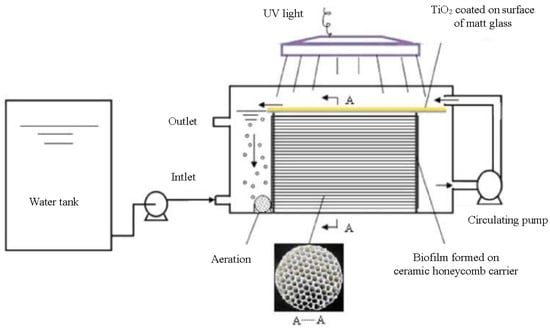
Figure 14.
The integrated photocatalytic–biological reactor (IPBR) with a close-up view of the ceramic honeycomb biofilm carrier [165], Copyright 2010, Springer.
4.2. Optimal Adjustment of Parameters
Understanding the kinetic characteristics of photocatalytic reactions is crucial in optimizing the conditions for such reactions during the design process of PWTRs. Kinetic studies typically cover the aspects of reaction mechanism, reaction rate, and reaction kinetics [167]. The discussion concerning photocatalytic reaction mechanisms and factors impacting their rates can be found in Section 2.1 and Section 3, respectively. As these parameters collectively contribute to the rate of photocatalytic reactions, the interplay among them needs to be considered. Therefore, establishing a reaction kinetics model based on reaction mechanisms and factors influencing reaction rates and utilizing such a model to guide the optimization of reaction parameters in practical applications can effectively enhance the PWTR’s performance. Irradiation intensity, flow rate, pollutant concentration, and other parameters are easily quantifiable, and the optimal parameter can be predicted by establishing mathematical models. Grao et al. designed a stainless steel mesh photocatalytic water treatment reactor to explore the effects of ultraviolet irradiation intensity, titanium dioxide coating mesh layers, coating thickness, flow rate, and initial dye concentration on the photocatalytic reaction and established a regression model that accurately predicted the best reaction conditions. Comparing the experimental data with the prediction results, it is found that the model has a good prediction effect [168]. In order to study the effects of hydraulic retention time and photocatalyst dosage on the degradation effect of sulfamethoxazole in membrane photocatalytic reactor systems, Asha et al. established a multiple nonlinear regression model based on experimental data, which effectively predicted the optimal hydraulic residence time and photocatalyst dosage in membrane photocatalytic reactor systems [169]. For parameters such as irradiation uniformity and reactor structure that are not easy to quantify, software simulation is a valuable tool to optimize. Matiazzo et al. simulated the light radiation field of the photocatalytic reactor to explore the effects of the distance among LEDs and the distance between LEDs and the irradiated objects in a photocatalytic reaction and determined the optimal structure distribution of LEDs [170]. Casado et al. optimized the light source of the photocatalytic reactor in order to improve the radiation uniformity in the photocatalytic reactor and designed four LED arrays with different arrangements. Through irradiation simulation and fine-tuning of the power of each LED, they identified a scheme with the most uniform irradiation [132]. Thus, mathematical models and computer simulation can effectively improve the photocatalytic efficiency of the PWTR at a lower cost [171].
4.3. Integration and Automatic Control of Each Module
The optimal parameter adjustment of the PWTR is discussed above. After obtaining the optimal parameters, how to control these parameters within an expected range during the reaction should also be considered. Therefore, the application of automatic control systems to the PWTR is essential. Khodadadian et al. investigated the application of automatic feedback and feedforward controllers to achieve an automated control circuit that can optimize photon utilization in photocatalytic water treatment. The system combines online analysis techniques with intelligent light sources to automatically regulate the radiated intensity in the LED photocatalytic reactor according to the photocatalytic reaction requirement, thus keeping the reaction rate constant [172]. The flowchart of this reactor is shown in Figure 15a. Pollutant concentration is controlled using the mass flow controller (MFC), pollutants are mixed by the controlled evaporator mixer (CEM), and the mixed pollutants are pumped into the reactor. The contaminant concentration in the reactor is measured by the online gas chromatograph (GC) to calculate the reaction rate. The feedforward controller (FFC) and feedback controller (FC) adjust the LED irradiation intensity based on the real-time reaction rate, achieving full control of the entire reaction process rate. The solid red line and arrows in the figure represent the path of nitrogen and oxygen transfer in the reactor, the solid black line and arrows represent the path of toluene and water transfer in the reactor, and the dashed black line and arrows represent the transfer path of signals between the MFC, FFC, and FC. Yu et al. designed an on-demand photocatalytic device that could successively monitor the activity of the bacterium bacillus subtilis via a sensor unit, as shown in Figure 15b. The solid lines and arrows in the figure indicate the transfer path of the solution in the reactor, while the dashed lines and arrows indicate the transmission path of the signals between the computer and the reactor. They first measured the optimal number of operating lamps at different pollutant concentrations, then fitted a linear function between the pollutant concentration and the optimal number of operating lamps, and then the computer controls the number of work lights in real time according to the concentration of pollutants obtained by the sensor, thereby reducing energy consumption [173]. Thus, the combination of auto-control technology and photocatalytic effluent reactor may be an effective way to improve photocatalytic efficiency and reduce energy consumption.
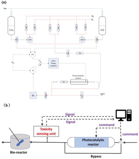
Figure 15.
(a) Flow diagram of the experimental setup. MFC: mass flow controller; BPC: back pressure controller; CEM: controlled evaporator mixer; TH: Thermo Hygrometer; PM: pressure meter; FC: feedback controller; FFC: feedforward controller [172], Copyright 2018, Elsevier. (b) Schematic diagram of a photocatalytic reactor that automatically adjusts light according to pollutant concentration [173], Copyright 2021, Elsevier.
5. Evaluation Method for PWTRs
In order to compare the performance of PWTRs, solid criteria are necessary. Evaluating a PWTR should focus primarily on efficiency, throughput, energy consumption, and equipment cost [174]. Currently, the commonly used criteria include reaction rate constant, specific removal rate, photon absorption efficiency, overall photonic efficiency, space time yield, and photocatalytic spatial and typical yields, as shown in Table 3. From the perspective of treatment effect of wastewater, reaction rate constant, removal rate, and specific removal rate are commonly used criteria to compare PWTR performance. Reaction rate constant reflects the amount of wastewater treated by the PWTR per unit time, and the higher the reaction rate constant value, the better the performance of the PWTR. The removal rate reflects the final treatment effect of the PWTR on pollutants. The specific removal rate refers to the ratio between the mass of pollutant removed and the mass of catalyst dosage, reflecting the utilization rate of PWTR to the catalyst. From the perspective of photon utilization, photon absorption and overall photon efficiency can also reflect the performance of the PWTR. Photon absorption efficiency reflects the absorption quantity of photons by the photocatalyst in a photochemical reaction. It can also be understood as the decomposition number of reactant molecules under the certain photon flux, which can embody the photon utilization rate [175]. Overall, photonic efficiency was first proposed by Zazueta et al. for optimizing the design parameters of the reactor. This assessment approach combined photon absorption efficiency () and uniformity of the distribution of the dimensionless radiation intensity (); the most efficient reactor design should be obtained when the product of and reaches a maximum [118]. Although the aforementioned criteria evaluate PWTR performance from different perspectives, energy consumption, which is crucial for industrial PWTR applications, is not thoroughly considered. In pursuit of a comprehensive evaluation criterion, Leblebici et al. proposed photocatalytic space–time yield (PSTY) based on the space–time yield (STY) criterion, comprehensively considering the impact of energy consumption [100]. PSTY is currently a relatively comprehensive criterion for PWTR performance, but it only considers the energy consumption generated by the light source. Although the energy consumption of the light source is the main source of energy consumption of PWTRs, accounting for about 70% of the overall energy consumption of PWTRs, the energy consumed by other modules should not be ignored. At the same time, this criterion does not reflect the utilization rate of the reactor for the photocatalyst. Therefore, further exploration is necessary to establish evaluation criteria that can more comprehensively assess the performance of PWTRs. Table 4 shows the values of each evaluation criterion for some of the photocatalytic reactors discussed in this review. Photon absorption efficiency and overall photon efficiency are not included in Table 4 because the data required to calculate the photon absorption efficiency are poorly available in the literature, and the overall photon efficiency calculation method is designed for a specific reactor. Nevertheless, these two criteria are equally important in practical applications and should not be ignored. In addition, this reflects the fact that the four evaluation criteria included in Table 4 are more commonly applied and easier to calculate. The analysis of Table 4 reveals that although the capillary microphotoreactor packed with TiO2-coated glass beads achieves the maximum reaction rate constant value, its small size and high energy consumption result in an unfavorable PSTY value. In contrast, the microcapillary photoreactor demonstrates a relatively high reaction rate while simultaneously taking into account light source energy consumption, thereby achieving the highest PSTY value. Thus, a balance between reaction rate constant and energy consumption must be considered in PWTR design to effectively reduce its industrial application cost.
Table 3.
Evaluation methods for PWTRs.
Table 4.
Comparison of reactor performance.
6. Summary and Outlook
In this review, the design of different types of PWTRs is discussed and analyzed according to the factors affecting the efficiency of photocatalytic reactions. We also discussed the optimization methods for PWTRs, such as the coupling of photocatalysis and other wastewater treatment technologies, the development of mathematical models to optimize the parameters of reaction conditions, and the application of automatic control technology in PWTRs. These methods can effectively reduce the cost and improve the efficiency of PWTRs. In the end, the currently employed evaluation criteria for the performance of PWTRs are discussed.
At present, the main reason why photocatalytic wastewater treatment technology is not widely used is that the photocatalytic efficiency is low and the industrialization cost is high. The key to solving these two problems is the preparation of an efficient photocatalyst and the design of a photocatalytic reactor with excellent performance, both of which are indispensable. In order to realize the industrial application of photocatalytic wastewater treatment technology, the newly prepared photocatalyst must have the following characteristics: good visible light response, high activity, high stability, low cost, no environmental footprint, and easy recovery and reusability. For the design of PWTRs, the low reaction rate of solar PWTRs and the high energy consumption of artificial sunlight source PWTRs are currently some of the main challenges, which can be solved by using high transmittance materials, optimizing the structure of the reactor to increase light reflection, using high-performance light sources, and optimizing light distribution. In addition, the scale-up of PWTRs is another big challenge. The expansion of PWTR scale often faces problems such as mass transfer limitation, radiation transfer limitation, and light source heat dissipation, so it is necessary to make corresponding design and optimization choices for PWTRs according to the actual situation.
Author Contributions
Conceptualization, J.M., F.P. and X.G.; methodology, J.M. and X.G.; validation, J.M. and X.G.; data curation, J.M.; writing—original draft preparation, J.M.; writing—review and editing, J.M., F.P., X.G. and J.Z.; supervision, J.Z. All authors have read and agreed to the published version of the manuscript.
Funding
This research was funded by the National Key R&D Program of China, Grant No. 2021YFB3501700, Shanghai Science and Technology Committee (STCSM) Science and Technology Innovation Program, Grant No. 22N21900400, National Natural Science Foundation of China, Grant No. 12104311, the Science and Technology Talent Development Fund for Young and Middle-aged Teachers of Shanghai Institute of Technology, Grant No. ZQ2022-3, and the Technology Innovation Funds of Small and Medium-sized Science and Technology Enterprises in Shanghai, Grant No.210H1066900 and Grant No. 220H1096700.
Data Availability Statement
Not applicable.
Acknowledgments
The authors would like to acknowledge the guidance of Yiming Li of Shanghai Shanshi Technology Co., Ltd. and the advice from Guofeng Zhao of East China Normal University and Zhenfeng Bian of Shanghai Normal University. The authors would like to acknowledge the support of the following funds: National Key R&D Program of China (Grant No. 2021YFB3501700), Shanghai Science and Technology Committee (STCSM) Science and Technology Innovation Program (Grant No. 22N21900400, Grant No. 23N21900100), National Natural Science Foundation of China (Grant No. 12104311), the Science and Technology Talent Development Fund for Young and Middle-aged Teachers of Shanghai Institute of Technology (Grant No. ZQ2022-3), and the Technology Innovation Funds of Small and Medium-sized Science and Technology Enterprises in Shanghai (Grant No.210H1066900, Grant No. 220H1096700).
Conflicts of Interest
The authors declare no conflict of interest.
References
- van Loosdrecht, M.C.; Brdjanovic, D. Water treatment. Anticipating the next century of wastewater treatment. Science 2014, 344, 1452–1453. [Google Scholar] [CrossRef] [PubMed]
- Chong, M.N.; Jin, B.; Chow, C.; Saint, C. Recent Developments in Photocatalytic Water Treatment Technology: A Review. Water Res. 2010, 44, 2997–3027. [Google Scholar] [CrossRef] [PubMed]
- Xiao, J.; Xie, Y.; Rabeah, J.; Brückner, A.; Cao, H. Visible-Light Photocatalytic Ozonation Using Graphitic C3N4 Catalysts: A Hydroxyl Radical Manufacturer for Wastewater Treatment. Acc. Chem. Res. 2020, 53, 1024–1033. [Google Scholar] [CrossRef] [PubMed]
- Masuda, S.; Sano, I.; Hojo, T.; Li, Y.Y.; Nishimura, O. The comparison of greenhouse gas emissions in sewage treatment plants with different treatment processes. Chemosphere 2018, 193, 581–590. [Google Scholar] [CrossRef]
- Xu, H.; Li, Y.; Ding, M.; Chen, W.; Wang, K.; Lu, C. Simultaneous removal of dissolved organic matter and nitrate from sewage treatment plant effluents using photocatalytic membranes. Water Res. 2018, 143, 250–259. [Google Scholar] [CrossRef]
- Fujishima, A.; Honda, K. Electrochemical photolysis of water at a semiconductor electrode. Nature 1972, 113, 4545–4548. [Google Scholar] [CrossRef]
- Hoffmann, M.R.; Martin, S.T.; Choi, W.Y.; Bahnemann, D.W. Environmental applications of semiconductor photocatalysis. Chem. Rev. 1995, 95, 69–96. [Google Scholar] [CrossRef]
- Vilar, V.J.P.; Amorim, C.C.; Li Puma, G.; Malato, S.; Dionysiou, D.D. Intensification of photocatalytic processes for niche applications in the area of water, wastewater and air treatment. Chem. Eng. J. 2017, 310, 329–330. [Google Scholar] [CrossRef]
- Nolan, M.; Iwaszuk, A.; Lucid, A.K.; Carey, J.J.; Fronzi, M. Design of Novel Visible Light Active Photocatalyst Materials: Surface Modified TiO2. Adv. Mater. 2016, 28, 5425–5446. [Google Scholar] [CrossRef]
- Li, J.; Yuan, H.; Zhang, W.; Jin, B.; Feng, Q.; Huang, J.; Jiao, Z. Advances in Z-scheme semiconductor photocatalysts for the photoelectrochemical applications: A review. Carbon Energy 2022, 4, 294–331. [Google Scholar] [CrossRef]
- Wang, D.; Mueses, M.A.; Marquez, J.A.C.; Machuca-Martinez, F.; Grcic, I.; Peralta Muniz Moreira, R.; Li Puma, G. Engineering and modeling perspectives on photocatalytic reactors for water treatment. Water Res. 2021, 202, 117421–117442. [Google Scholar] [CrossRef] [PubMed]
- Ghiyasiyan-Arani, M.; Salavati-Niasari, M. Synergic and coupling effect between SnO2 nanoparticles and hierarchical AlV3O9 microspheres toward emerging electrode materials for lithium-ion battery devices. Inorg. Chem. Front. 2021, 8, 2735–2748. [Google Scholar] [CrossRef]
- Mancuso, A.; Iervolino, G. Synthesis and Application of Innovative and Environmentally Friendly Photocatalysts: A Review. Catalysts 2022, 12, 1074. [Google Scholar] [CrossRef]
- Zonouz, A.F.; Ashrafi, M.; Ghiyasiyan-Arani, M.; Hamadanian, M. Effect of sol–gel synthesized Al0.1Zr0.9O1.95 nanoparticles and PVP on PVDF-based separators in lithium-ion battery performance: The RSM study. J. Elastomers Plast. 2020, 53, 241–257. [Google Scholar] [CrossRef]
- Han, P.; Martens, W.; Waclawik, E.R.; Sarina, S.; Zhu, H. Metal Nanoparticle Photocatalysts: Synthesis, Characterization, and Application. Part. Part. Syst. Charact. 2018, 35, 1700489–1700505. [Google Scholar] [CrossRef]
- Loeb, S.K.; Alvarez, P.J.J.; Brame, J.A.; Cates, E.L.; Choi, W.; Crittenden, J.; Dionysiou, D.D.; Li, Q.; Li-Puma, G.; Quan, X.; et al. The Technology Horizon for Photocatalytic Water Treatment: Sunrise or Sunset? Environ. Sci. Technol. 2019, 53, 2937–2947. [Google Scholar] [CrossRef]
- Kanafin, Y.N.; Kanafina, D.; Malamis, S.; Katsou, E.; Inglezakis, V.J.; Poulopoulos, S.G.; Arkhangelsky, E. Anaerobic Membrane Bioreactors for Municipal Wastewater Treatment: A Literature Review. Membranes 2021, 11, 967. [Google Scholar] [CrossRef]
- Ollis, D.F.; Pelizzetti, E.; Serpone, N. Photocatalyzed destruction of water contaminants. Environ. Sci. Technol. 1991, 25, 1522–1529. [Google Scholar] [CrossRef]
- Buzzetti, L.; Crisenza, G.; Melchiorre, P. Mechanistic Studies in Photocatalysis. Angew. Chem. Int. Ed. 2019, 58, 3730–3747. [Google Scholar] [CrossRef]
- Nosaka, Y.; Nosaka, A. Understanding Hydroxyl Radical (OH) Generation Processes in Photocatalysis (Open Access Viewpoint). ACS Energy Lett. 2016, 1, 356–359. [Google Scholar] [CrossRef]
- Nosaka, Y.; Nosaka, A.Y. Generation and Detection of Reactive Oxygen Species in Photocatalysis. Chem. Rev. 2017, 117, 11302–11336. [Google Scholar] [CrossRef] [PubMed]
- Li, N.; Ma, J.; Zhang, Y.; Zhang, L.; Jiao, T. Recent Developments in Functional Nanocomposite Photocatalysts for Wastewater Treatment: A Review. Adv. Sustain. Syst. 2022, 6, 2200106–2200119. [Google Scholar] [CrossRef]
- Li, X.; Xie, J.; Jiang, C.; Yu, J.; Zhang, P. Review on design and evaluation of environmental photocatalysts. Front. Environ. Sci. Eng. 2018, 12, 32–63. [Google Scholar] [CrossRef]
- Araújo, R.G.; Rodríguez-Hernandéz, J.A.; González-González, R.B.; Macias-Garbett, R.; Martínez-Ruiz, M.; Reyes-Pardo, H.; Hernández Martínez, S.A.; Parra-Arroyo, L.; Melchor-Martínez, E.M.; Sosa-Hernández, J.E.; et al. Detection and Tertiary Treatment Technologies of Poly-and Perfluoroalkyl Substances in Wastewater Treatment Plants. Front. Environ. Sci. 2022, 10, 864894–864914. [Google Scholar] [CrossRef]
- Demirbas, A.; Edris, G.; Alalayah, W.M. Sludge production from municipal wastewater treatment in sewage treatment plant. Energy Sources Part A Recovery Util. Environ. Eff. 2017, 39, 999–1006. [Google Scholar] [CrossRef]
- Melvin, S.D.; Leusch, F.D.L. Removal of trace organic contaminants from domestic wastewater: A meta-analysis comparison of sewage treatment technologies. Environ. Int. 2016, 92–93, 183–188. [Google Scholar] [CrossRef]
- Van Nieuwenhuijzen, A.F.; Van Bentem, A.G.N.; Buunnen, A.; Reitsma, B.A.; Uijterlinde, C.A. The limits and ultimate possibilities of technology of the activated sludge process. Water Sci. Technol. 2008, 58, 1671–1677. [Google Scholar] [CrossRef]
- Gao, T.; Xiao, K.; Zhang, J.; Xue, W.; Wei, C.; Zhang, X.; Liang, S.; Wang, X.; Huang, X. Techno-economic characteristics of wastewater treatment plants retrofitted from the conventional activated sludge process to the membrane bioreactor process. Front. Environ. Sci. Eng. 2022, 16, 49–60. [Google Scholar] [CrossRef]
- Li, W.; Yu, H. Advances in Energy-Producing Anaerobic Biotechnologies for Municipal Wastewater Treatment. Engineering 2016, 2, 438–446. [Google Scholar] [CrossRef]
- Ghumra, D.P.; Agarkoti, C.; Gogate, P.R. Improvements in effluent treatment technologies in Common Effluent Treatment Plants (CETPs): Review and recent advances. Process Saf. Environ. Prot. 2021, 147, 1018–1051. [Google Scholar] [CrossRef]
- Ozgun, H.; Cicekalan, B.; Akdag, Y.; Koyuncu, I.; Ozturk, I. Comparative evaluation of cost for preliminary and tertiary municipal wastewater treatment plants in Istanbul. Sci. Total Environ. 2021, 778, 146258–146267. [Google Scholar] [CrossRef] [PubMed]
- Li, X.; Li, M.; Mei, Q.; Niu, S.; Zhou, J.L. Aging microplastics in wastewater pipeline networks and treatment processes: Physicochemical characteristics and Cd adsorption. Sci. Total Environ. 2021, 797, 148940–148949. [Google Scholar] [CrossRef] [PubMed]
- Cates, E.L. Photocatalytic Water Treatment: So Where Are We Going with This? Environ. Sci. Technol. 2017, 51, 757–758. [Google Scholar] [CrossRef]
- Gunten, U.V. Oxidation Processes in Water Treatment: Are We on Track? Environ. Sci. Technol. 2018, 52, 5062–5075. [Google Scholar] [CrossRef]
- Shukla, K.; Agarwalla, S.; Duraiswamy, S.; Gupta, R.K. Recent advances in heterogeneous micro-photoreactors for wastewater treatment application. Chem. Eng. Sci. 2021, 235, 116511–116529. [Google Scholar] [CrossRef]
- Klementova, S.; Kahoun, D.; Doubková, L.; Frejlachova, K.; Zlamal, M. Catalytic photodegradation of pharmaceuticals—Homogeneous and heterogeneous photocatalysis. Photochem. Photobiol. 2017, 16, 67–71. [Google Scholar] [CrossRef]
- Mak, C.H.; Han, X.; Du, M.; Kai, J.-J.; Tsang, K.F.; Jia, G.; Cheng, K.-C.; Shen, H.-H.; Hsu, H.-Y. Heterogenization of homogeneous photocatalysts utilizing synthetic and natural support materials. J. Mater. Chem. A 2021, 9, 4454–4504. [Google Scholar] [CrossRef]
- Wetchakun, K.; Wetchakun, N.; Sakulsermsuk, S. An overview of solar/visible light-driven heterogeneous photocatalysis for water purification: TiO2- and ZnO-based photocatalysts used in suspension photoreactors. J. Ind. Eng. Chem. 2019, 71, 19–49. [Google Scholar] [CrossRef]
- Long, Z.; Li, Q.; Wei, T.; Zhang, G.; Ren, Z. Historical development and prospects of photocatalysts for pollutant removal in water. J. Hazard. Mater. 2020, 395, 122599–122618. [Google Scholar] [CrossRef]
- Guo, Y.; Li, H.; Ma, W.; Shi, W.; Zhu, Y.; Choi, W. Photocatalytic activity enhanced via surface hybridization. Carbon Energy 2020, 2, 308–349. [Google Scholar] [CrossRef]
- Wu, M.; Gong, Y.; Nie, T.; Zhang, J.; Wang, R.; Wang, H.; He, B. Template-free synthesis of nanocage-like g-C3N4 with high surface area and nitrogen defects for enhanced photocatalytic H-2 activity. J. Mater. Chem. A 2019, 7, 5324–5332. [Google Scholar] [CrossRef]
- Wk, A.; Bjcb, C.; Ydk, B.; Hos, A. Sub-micro photocatalytic TiO2 particles for a water depollution: Comparable removal efficiency to commercial P25 and easy separation via a simple sedimentation. Catal. Today 2021, 403, 47–57. [Google Scholar] [CrossRef]
- Fu, Z.A.; Huang, C.B.; Zhao, X.A.; Fu, Z.C. Study on preparation and recovery of magnetic BiOI/rGO/Fe3O4 composite photocatalyst. Results Phys. 2020, 16, 102931–102934. [Google Scholar] [CrossRef]
- Dong, J.; Shi, Y.; Huang, C.; Wu, Q.; Zeng, T.; Yao, W. A New and stable Mo-Mo2C modified g-C3N4 photocatalyst for efficient visible light photocatalytic H2 production. Appl. Catal. B Environ. 2019, 243, 27–35. [Google Scholar] [CrossRef]
- Chu, Z.; Qiu, L.; Chen, Y.; Zhuang, Z.; Du, P.; Xiong, J. TiO2-loaded carbon fiber: Microwave hydrothermal synthesis and photocatalytic activity under UV light irradiation. J. Phys. Chem. Solids 2020, 136, 109138–109161. [Google Scholar] [CrossRef]
- Kavitha, R.; Nithya, P.M.; Girish Kumar, S. Noble metal deposited graphitic carbon nitride based heterojunction photocatalysts. Appl. Surf. Sci. 2020, 508, 145142–145231. [Google Scholar] [CrossRef]
- Lammer, A.D.; Thiabaud, G.; Brewster, J.T.; Alaniz, J.; Bender, J.A.; Sessler, J.L. Lanthanide Texaphyrins as Photocatalysts. Inorg. Chem. 2018, 57, 3458–3464. [Google Scholar] [CrossRef]
- Radhika, N.P.; Selvin, R.; Kakkar, R.; Umar, A. Recent advances in nano-photocatalysts for organic synthesis. Arab. J. Chem. 2019, 12, 4550–4578. [Google Scholar] [CrossRef]
- Ali, I.; Asim, M.; Khan, T.A. Low cost adsorbents for the removal of organic pollutants from wastewater. J. Environ. Manag. 2012, 113, 170–183. [Google Scholar] [CrossRef]
- Baaloudj, O.; Assadi, I.; Nasrallah, N.; Jery, A.E.; Assadi, A.A. Simultaneous removal of antibiotics and inactivation of antibiotic-resistant bacteria by photocatalysis: A review. J. Water Process Eng. 2021, 42, 102089–102099. [Google Scholar] [CrossRef]
- Vaya, D.; Surolia, P.K. Semiconductor based photocatalytic degradation of pesticides: An overview. Environ. Technol. Innov. 2020, 20, 101128–101152. [Google Scholar] [CrossRef]
- Tahir, M.B.; Kiran, H.; Iqbal, T. The detoxification of heavy metals from aqueous environment using Nano-Photocatalysis approach: A review. Environ. Sci. Pollut. Res. 2019, 26, 10515–10528. [Google Scholar] [CrossRef] [PubMed]
- Colina-Marquez, J.; Machuca-Mabtiez, F.; Puma, G.L. Photocatalytic Mineralization of Commercial Herbicides in a Pilot-Scale Solar CPC Reactor: Photoreactor Modeling and Reaction Kinetics Constants Independent of Radiation Field. Environ. Sci. Technol. 2009, 43, 8953–8960. [Google Scholar] [CrossRef] [PubMed]
- Bhatkhande, D. Photocatalytic and photochemical degradation of nitrobenzene using artificial ultraviolet light. Chem. Eng. J. 2004, 102, 283–290. [Google Scholar] [CrossRef]
- Oller, I.; Gernjak, W.; Maldonado, M.I.; Perez-Estrada, L.A.; Sanchez-Perez, J.A.; Malato, S. Solar photocatalytic degradation of some hazardous water-soluble pesticides at pilot-plant scale. J. Hazard. Mater. 2006, 138, 507–517. [Google Scholar] [CrossRef]
- Martín-Sómer, M.; Pablos, C.; Grieken, R.V.; Marugán, J. Influence of Light Distribution on The Performance of Photocatalytic Reactors: Led vs Mercury Lamps. Appl. Catal. B Environ. 2017, 215, 1–7. [Google Scholar] [CrossRef]
- Song, K.; Mohseni, M.; Taghipour, F. Application of ultraviolet light-emitting diodes (UV-LEDs) for water disinfection: A review. Water Res. 2016, 94, 341–349. [Google Scholar] [CrossRef]
- Ibrahim, M.; Macadam, J.; Autin, O.; Jefferson, B. Evaluating the impact of LED bulb development on the economic viability of ultraviolet technology for disinfection. Environ. Technol. 2014, 35, 400–406. [Google Scholar] [CrossRef]
- Alpert, D.J.; Sprung, J.L.; Pacheco, J.E.; Prairie, M.R.; Reilly, H.E.; Milne, T.A.; Nimlos, M.R. Sandia National Laboratories’ work in solar detoxification of hazardous wastes. Sol. Energy Mater. 1991, 24, 594–607. [Google Scholar] [CrossRef]
- Minero, C.; Pelizzetti, E.; Malato, S.; Blanco, J. Large solar plant photocatalytic water decontamination: Degradation of pentachlorophenol. Chemosphere 1993, 26, 2103–2119. [Google Scholar] [CrossRef]
- Hofstadler, K.; Bauer, R.; Novalic, S.; Heisler, G. New reactor design for photocatalytic wastewater treatment with TiO2 immobilized on fused-silica glass fibers: Photomineralization of 4-chlorophenol. Environ. Sci. Technol. 1994, 28, 670–674. [Google Scholar] [CrossRef] [PubMed]
- Minero, C.; Pelizzetti, E.; Malato, S.; Blanco, J. Large solar plant photocatalytic water decontamination: Degradation of atrazine. Sol. Energ. 1996, 56, 411–419. [Google Scholar] [CrossRef]
- van Well, M.; Dillert, R.H.G.; Bahnemann, D.W.; Benz, V.W.; Mueller, M.A. A novel nonconcentrating reactor for solar water detoxification. J. Sol. Energ. Eng. 1997, 119, 114–119. [Google Scholar] [CrossRef]
- Freudenhammer, H.; Bahnemann, D.; Bousselmi, L.; Geissen, S.-U.; Ghrabi, A.; Saleh, F.; Si-Salah, A.; Siemon, U.; Vogelpohl, A. Detoxification and recycling of wastewater by solar-catalytic treatment. Water Sci. Technol. 1997, 35, 149–156. [Google Scholar] [CrossRef]
- Puma, G.L.; Yue, P.L. A laminar falling film slurry photocatalytic reactor. Part II—Experimental validation of the model. Chem. Eng. Sci. 1998, 53, 3007–3021. [Google Scholar] [CrossRef]
- Vidal, A.; Diaz, A.I.; El Hiraiki, A.; Romero, M.; Muguruza, I.; Senhaji, F.; Gonzalez, J. Solar photocatalysis for detoxification and disinfection of contaminated water: Pilot plant studies. Catal. Today 1999, 54, 283–290. [Google Scholar] [CrossRef]
- Klare, M.; Scheen, J.; Vogelsang, K.; Jacobs, H.; Broekaert, J.A.C. Degradation of short-chain alkyl- and alkanolamines by TiO2- and Pt/TiO2-assisted photocatalysis. Chemosphere 2000, 41, 353–362. [Google Scholar] [CrossRef]
- Yatmaz, H.C.; Wallis, C.; Howarth, C.R. The spinning disc reactor—Studies on a novel TiO2 photocatalytic reactor. Chemosphere 2001, 42, 397–403. [Google Scholar] [CrossRef]
- Bousselmi, L.; Geissen, S.U.; Schroeder, H. Textile wastewater treatment and reuse by solar catalysis: Results from a pilot plant in Tunisia. Water Sci. Technol. 2004, 49, 331–337. [Google Scholar] [CrossRef]
- Sichel, C.; Tello, J.; de Cara, M.; Fernández-Ibáñez, P. Effect of UV solar intensity and dose on the photocatalytic disinfection of bacteria and fungi. Catal. Today 2007, 129, 152–160. [Google Scholar] [CrossRef]
- Benotti, M.J.; Stanford, B.D.; Wert, E.C.; Snyder, S.A. Evaluation of a photocatalytic reactor membrane pilot system for the removal of pharmaceuticals and endocrine disrupting compounds from water. Water Res. 2009, 43, 1513–1522. [Google Scholar] [CrossRef] [PubMed]
- Duran, A.; Monteagudo, J.M.; San Martin, I. Photocatalytic treatment of an industrial effluent using artificial and solar UV radiation: An operational cost study on a pilot plant scale. J. Environ. Manag. 2012, 98, 1–4. [Google Scholar] [CrossRef] [PubMed]
- Quiñones, D.H.; Álvarez, P.M.; Rey, A.; Beltrán, F.J. Removal of emerging contaminants from municipal WWTP secondary effluents by solar photocatalytic ozonation. A pilot-scale study. Sep. Purif. Technol. 2015, 149, 132–139. [Google Scholar] [CrossRef]
- Aguas, Y.; Hincapie, M.; Fernandez-Ibanez, P.; Polo-Lopez, M.I. Solar photocatalytic disinfection of agricultural pathogenic fungi (Curvularia sp.) in real urban wastewater. Sci. Total Environ. 2017, 607–608, 1213–1224. [Google Scholar] [CrossRef] [PubMed]
- Haranaka-Funai, D.; Didier, F.; Giménez, J.; Marco, P.; Esplugas, S.; Machulek-Junior, A. Photocatalytic treatment of valproic acid sodium salt with TiO2 in different experimental devices: An economic and energetic comparison. Chem. Eng. J. 2017, 327, 656–665. [Google Scholar] [CrossRef]
- Duran, A.; Monteagudo, J.M.; San Martin, I.; Merino, S. Photocatalytic degradation of aniline using an autonomous rotating drum reactor with both solar and UV-C artificial radiation. J. Environ. Manag. 2018, 210, 122–130. [Google Scholar] [CrossRef] [PubMed]
- Moreira, N.F.F.; Narciso-da-Rocha, C.; Polo-Lopez, M.I.; Pastrana-Martinez, L.M.; Faria, J.L.; Manaia, C.M.; Fernandez-Ibanez, P.; Nunes, O.C.; Silva, A.M.T. Solar treatment (H2O2, TiO2-P25 and GO-TiO2 photocatalysis, photo-Fenton) of organic micropollutants, human pathogen indicators, antibiotic resistant bacteria and related genes in urban wastewater. Water Res. 2018, 135, 195–206. [Google Scholar] [CrossRef]
- Bansal, P.; Verma, A. In-situ dual effect studies using novel Fe-TiO2 composite for the pilot-plant degradation of pentoxifylline. Chem. Eng. J. 2018, 332, 682–694. [Google Scholar] [CrossRef]
- Fernandes, A.; Gągol, M.; Makoś, P.; Khan, J.A.; Boczkaj, G. Integrated photocatalytic advanced oxidation system (TiO2/UV/O3/H2O2) for degradation of volatile organic compounds. Sep. Purif. Technol. 2019, 224, 1–14. [Google Scholar] [CrossRef]
- Mofrad, M.M.G.; Pourzamani, H.; Amin, M.M.; Parseh, I.; Alipour, M. In situ treatment of metalworking wastewater by chemical addition-dissolved air flotation coupled with UV, H2O2 & ZnO. Heliyon 2020, 6, e030910–e030921. [Google Scholar] [CrossRef]
- Samy, M.; Ibrahim, M.G.; Fujii, M.; Diab, K.E.; ElKady, M.; Gar Alalm, M. CNTs/MOF-808 painted plates for extended treatment of pharmaceutical and agrochemical wastewaters in a novel photocatalytic reactor. Chem. Eng. J. 2021, 406, 127152–127167. [Google Scholar] [CrossRef]
- Balakrishnan, A.; Gopalram, K.; Appunni, S. Photocatalytic degradation of 2,4-dicholorophenoxyacetic acid by TiO2 modified catalyst: Kinetics and operating cost analysis. Environ. Sci. Pollut. Res. Int. 2021, 28, 33331–33343. [Google Scholar] [CrossRef] [PubMed]
- Rani, C.N.; Karthikeyan, S. Synergic effects on degradation of a mixture of polycyclic aromatic hydrocarbons in a UV slurry photocatalytic membrane reactor and its cost estimation. Chem. Eng. Process.-Process Intensif. 2021, 159, 108179–108189. [Google Scholar] [CrossRef]
- Ballari, M.d.l.M.; Alfano, O.M.; Cassano, A.E. Mass transfer limitations in slurry photocatalytic reactors: Experimental validation. Chem. Eng. Sci. 2010, 65, 4931–4942. [Google Scholar] [CrossRef]
- Claes, T.; Dilissen, A.; Leblebici, M.E.; Van Gerven, T. Translucent packed bed structures for high throughput photocatalytic reactors. Chem. Eng. J. 2019, 361, 725–735. [Google Scholar] [CrossRef]
- Mukherjee, P.S.; Ray, A.K. Major Challenges in the Design of a Large-Scale Photocatalytic Reactor for Water Treatment. Chem. Eng. Technol. 1999, 22, 253–260. [Google Scholar] [CrossRef]
- Subramanian, M.; Kannan, A. Photocatalytic degradation of phenol in a rotating annular reactor. Chem. Eng. Sci. 2010, 65, 2727–2740. [Google Scholar] [CrossRef]
- Cao, F.; Zhao, L.; Guo, L.; Li, H.; Chao, H. Optimization of the concentration field in a suspended photocatalytic reactor. Energy 2014, 74, 140–146. [Google Scholar] [CrossRef]
- Tokode, O.; Prabhu, R.; Lawton, L.A.; Robertson, P. A photocatalytic impeller reactor for gas phase heterogeneous photocatalysis. J. Environ. Chem. Eng. 2017, 5, 3942–3948. [Google Scholar] [CrossRef]
- Boyjoo, Y.; Ang, M.; Pareek, V. CFD simulation of a pilot scale slurry photocatalytic reactor and design of multiple-lamp reactors. Chem. Eng. Ence 2014, 111, 266–277. [Google Scholar] [CrossRef]
- Sundar, K.P.; Kanmani, S. Progression of Photocatalytic reactors and it’s comparison: A Review. Chem. Eng. Res. Des. 2020, 154, 135–150. [Google Scholar] [CrossRef]
- Jo, W.-K.; Park, G.T.; Tayade, R.J. Synergetic effect of adsorption on degradation of malachite green dye under blue LED irradiation using spiral-shaped photocatalytic reactor. J. Chem. Technol. Biotechnol. 2015, 90, 2280–2289. [Google Scholar] [CrossRef]
- Le, C.C.; Wismer, M.K.; Shi, Z.C.; Zhang, R.; Conway, D.V.; Li, G.; Vachal, P.; Davies, I.W.; MacMillan, D.W.C. A General Small-Scale Reactor To Enable Standardization and Acceleration of Photocatalytic Reactions. ACS Cent. Sci. 2017, 3, 647–653. [Google Scholar] [CrossRef]
- Pellegrino, F.; Pellutiè, L.; Sordello, F.; Minero, C.; Ortel, E.; Hodoroaba, V.D.; Maurino, V. Influence of agglomeration and aggregation on the photocatalytic activity of TiO2 nanoparticles. Appl. Catal. B Environ. 2017, 216, 80–87. [Google Scholar] [CrossRef]
- Leblebici, M.E.; Rongé, J.; Martens, J.A.; Stefanidis, G.D.; Van Gerven, T. Computational modelling of a photocatalytic UV-LED reactor with internal mass and photon transfer consideration. Chem. Eng. J. 2015, 264, 962–970. [Google Scholar] [CrossRef]
- Kim, H.; Kwon, H.; Song, R.; Shin, S.; Ham, S.-Y.; Park, H.-D.; Lee, J.; Fischer, P.; Bodenschatz, E. Hierarchical optofluidic microreactor for water purification using an array of TiO2 nanostructures. NPJ Clean Water 2022, 5, 62–72. [Google Scholar] [CrossRef]
- Hakki, H.K.; Allahyari, S. Intensification of photocatalytic wastewater treatment using a novel continuous microcapillary photoreactor irradiated by visible LED lights. Chem. Eng. Process. 2022, 175, 108937–108947. [Google Scholar] [CrossRef]
- Teixeira, S.; Magalhes, B.; Martins, P.M.; Kühn, K.; Soler, L.; Lanceros-Méndez, S.; Cuniberti, G. Photocatalysis: Reusable Photocatalytic Optical Fibers for Underground, Deep-Sea, and Turbid Water Remediation (Global Challenges 3/2018). Glob. Chall. 2018, 2, 1870030–1870038. [Google Scholar] [CrossRef]
- Zeng, Z.; Jing, D.; Guo, L. Efficient hydrogen production in a spotlight reactor with plate photocatalyst of TiO2/NiO heterojunction supported on nickel foam. Energy 2021, 228, 120578–120588. [Google Scholar] [CrossRef]
- Vezzoli, M.; Martens, W.N.; Bell, J.M. Investigation of phenol degradation: True reaction kinetics on fixed film titanium dioxide photocatalyst. Appl. Catal. A Gen. 2011, 404, 155–163. [Google Scholar] [CrossRef]
- Plantard, G.; Goetz, V. Correlations between optical, specific surface and photocatalytic properties of media integrated in a photo-reactor. Chem. Eng. J. 2014, 252, 194–201. [Google Scholar] [CrossRef]
- Moreno-SanSegundo, J.; Casado, C.; Marugán, J. Enhanced numerical simulation of photocatalytic reactors with an improved solver for the radiative transfer equation. Chem. Eng. J. 2020, 388, 124183–124208. [Google Scholar] [CrossRef]
- Li, K.; He, Y.; Xu, Y.; Wang, Y.; Jia, J. Degradation of rhodamine B using an unconventional graded photoelectrode with wedge structure. Environ. Sci. Technol. 2011, 45, 7401–7407. [Google Scholar] [CrossRef] [PubMed]
- Visan, A.; Rafieian, D.; Ogieglo, W.; Lammertink, R.G.H. Modeling intrinsic kinetics in immobilized photocatalytic microreactors. Appl. Catal. B Environ. 2014, 150–151, 93–100. [Google Scholar] [CrossRef]
- Leblebici, M.E.; Stefanidis, G.D.; Gerven, T.V. Comparison of photocatalytic space-time yields of 12 reactor designs for wastewater treatment. Chem. Eng. Process. Process Intensif. 2015, 97, 106–111. [Google Scholar] [CrossRef]
- Zhang, Z.; Wu, H.; Yuan, Y.; Fang, Y.; Jin, L. Development of a novel capillary array photocatalytic reactor and application for degradation of azo dye. Chem. Eng. J. 2012, 184, 9–15. [Google Scholar] [CrossRef]
- Sza, B.; Jie, Z.; Jian, S.B.; Ztac, D. Capillary microphotoreactor packed with TiO2-coated glass beads: An efficient tool for photocatalytic reaction. Chem. Eng. Process.-Process Intensif. 2020, 147, 107746–107769. [Google Scholar] [CrossRef]
- Claes, T.; Gerven, T.V.; Leblebici, M.E. Design considerations for photocatalytic structured packed bed reactors. Chem. Eng. J. 2021, 403, 126355–126397. [Google Scholar] [CrossRef]
- Kouamé, A.N.; Masson, R.; Robert, D.; Keller, N.; Keller, V. β-SiC foams as a promising structured photocatalytic support for water and air detoxification. Catal. Today 2013, 209, 13–20. [Google Scholar] [CrossRef]
- Ribbens, S.; Tytgat, T.; Hauchecorne, B.; Smits, M.; Meynen, V.; Cool, P.; Martens, J.A.; Lenaerts, S. The benefit of glass bead supports for efficient gas phase photocatalysis: Case study of a commercial and a synthesised photocatalyst. Chem. Eng. J. 2011, 174, 318–325. [Google Scholar] [CrossRef]
- Hou, J.; Liu, H.; Zhao, L. Optimization of radiation absorption model in solar photocatalytic reactors: Coupling photocatalyst concentration distribution. Appl. Therm. Eng. 2019, 160, 114090–114097. [Google Scholar] [CrossRef]
- Gad-Allah, T.A.; Kato, S.; Satokawa, S.; Kojima, T. Treatment of synthetic dyes wastewater utilizing a magnetically separable photocatalyst (TiO2/SiO2/Fe3O4): Parametric and kinetic studies. Desalination 2009, 244, 1–11. [Google Scholar] [CrossRef]
- Malato, S.; Maldonado, M.I.; Fernández-Ibáñez, P.; Oller, I.; Polo, I.; Sánchez-Moreno, R. Inmaculada Decontamination and disinfection of water by solar photocatalysis: The pilot plants of the Plataforma Solar de Almeria. Mater. Sci. Semicond. Process. 2016, 42, 15–23. [Google Scholar] [CrossRef]
- Saravanan, P.; Pakshirajan, K.; Saha, P. Degradation of phenol by TiO2-based heterogeneousphotocatalysts in presence of sunlight. J. Hydro-Environ. Res. 2009, 3, 45–50. [Google Scholar] [CrossRef]
- Ashouri, R.; Rasekh, B.; Kasaeian, A.; Sheikhpour, M.; Yazdian, F.; Mobarakeh, M.D. Effect of ZnO-based nanophotocatalyst on degradation of aniline. J. Mol. Model. 2021, 27, 1–14. [Google Scholar] [CrossRef] [PubMed]
- Mahmoodi, N.M.; Arami, M.; Limaee, N.Y.; Tabrizi, N.S. Kinetics of heterogeneous photocatalytic degradation of reactive dyes in an immobilized TiO2 photocatalytic reactor. J. Colloid Interface Sci. 2006, 295, 159–164. [Google Scholar] [CrossRef]
- Badri, R.; Goutham, N.R.; Srikanth, B.; Gopinath, K.P. A novel nano-sized calcium hydroxide catalyst prepared from clam shells for the photodegradation of methyl red dye. J. Environ. Chem. Eng. 2018, 6, 3640–3647. [Google Scholar] [CrossRef]
- Khatami, M.; Iravani, S. Green and Eco-Friendly Synthesis of Nanophotocatalysts: An Overview. Comments Inorg. Chem. 2021, 41, 133–187. [Google Scholar] [CrossRef]
- Jacinto, M.J.; Ferreira, L.F.; Silva, V.C. Magnetic materials for photocatalytic applications—A review. J. Sol-Gel Sci. Technol. 2020, 96, 1–14. [Google Scholar] [CrossRef]
- Li, Q.; Kong, H.; Jia, R.; Shao, J.; He, Y. Enhanced catalytic degradation of amoxicillin with TiO2 –Fe3O4 composites via a submerged magnetic separation membrane photocatalytic reactor (SMSMPR). RSC Adv. 2019, 9, 12538–12546. [Google Scholar] [CrossRef]
- Yan, H.; Liu, L.; Wang, R.; Zhu, W.; Ren, X.; Luo, L.; Zhang, X.; Luo, S.; Ai, X.; Wang, J. Binary composite MoS2/TiO2 nanotube arrays as a recyclable and efficient photocatalyst for solar water disinfection. Chem. Eng. J. 2020, 401, 126052–126060. [Google Scholar] [CrossRef]
- Sorathiya, K.; Mishra, B.; Kalarikkal, A.; Reddy, K.P.; Gopinath, C.S.; Khushalani, D. Enhancement in Rate of Photocatalysis Upon Catalyst Recycling. Sci. Rep. 2016, 6, 35075–35083. [Google Scholar] [CrossRef]
- Destaillats, H.; Puma, G.L. Radiation field modeling and optimization of a compact and modular multi-plate photocatalytic reactor (MPPR) for air/water purification by Monte Carlo method. Chem. Eng. J. 2013, 217, 475–485. [Google Scholar] [CrossRef]
- Jiang, L.; Yuan, X.; Zeng, G.; Wu, Z.; Liang, J.; Chen, X.; Leng, L.; Wang, H.; Wang, H. Metal-free efficient photocatalyst for stable visible-light photocatalytic degradation of refractory pollutant. Appl. Catal. B Environ. 2018, 211, 715–725. [Google Scholar] [CrossRef]
- Abdel-Maksoud, Y.; Imam, E.; Ramadan, A. TiO2 Solar Photocatalytic Reactor Systems: Selection of Reactor Design for Scale-up and Commercialization—Analytical Review. Catalysts 2016, 6, 138. [Google Scholar] [CrossRef]
- Keller, N.; Ivanez, J.; Highfield, J.; Ruppert, A.M. Photo-/thermal synergies in heterogeneous catalysis: Towards low-temperature (solar-driven) processing for sustainable energy and chemicals. Appl. Catal. B Environ. 2021, 296, 120320–120356. [Google Scholar] [CrossRef]
- Jebasingh, V.K.; Herbert, G.M.J. A review of solar parabolic trough collector. Renew. Sustain. Energy Rev. 2016, 54, 1085–1091. [Google Scholar] [CrossRef]
- Fendrich, M.; Quaranta, A.; Orlandi, M.; Bettonte, M.; Miotello, A. Solar Concentration for Wastewaters Remediation: A Review of Materials and Technologies. Appl. Sci. 2018, 9, 118. [Google Scholar] [CrossRef]
- Otálvaro-Marín, H.L.; Mueses, M.A.; Crittenden, J.C.; Machuca-Martinez, F. Solar photoreactor design by the photon path length and optimization of the radiant field in a TiO2 -based CPC reactor. Chem. Eng. J. 2017, 315, 283–295. [Google Scholar] [CrossRef]
- Colina-Marquez, J.; Castilla-Caballero, D.; Machuca-Martinez, F. Modeling of a falling-film photocatalytic reactor: Fluid dynamics for turbulent regime. Appl. Math. Model. 2016, 40, 4812–4821. [Google Scholar] [CrossRef]
- Chaúque, B.J.M.; Brandão, F.G.; Rott, M.B. Development of solar water disinfection systems for large-scale public supply, state of the art, improvements and paths to the future—A systematic review. J. Environ. Chem. Eng. 2022, 10, 107887–107910. [Google Scholar] [CrossRef]
- Casado, C.; Timmers, R.; Sergejevs, A.; Clarke, C.T.; Allsopp, D.W.E.; Bowen, C.R.; van Grieken, R.; Marugán, J. Design and validation of a LED-based high intensity photocatalytic reactor for quantifying activity measurements. Chem. Eng. J. 2017, 327, 1043–1055. [Google Scholar] [CrossRef]
- Zhong, W.; Wang, D.; Xu, X. Phenol removal efficiencies of sewage treatment processes and ecological risks associated with phenols in effluents. J. Hazard. Mater. 2012, 217–218, 286–292. [Google Scholar] [CrossRef] [PubMed]
- Würtele, M.A.; Kolbe, T.; Lipsz, M.; Külberg, A.; Weyers, M.; Kneissl, M.; Jeke, M. Application of GaN-based ultraviolet-C light emitting diodes—UV LEDs—For water disinfection. Water Res. A J. Int. Water Assoc. 2011, 45, 1481–1489. [Google Scholar] [CrossRef]
- Rodríguez-Chueca, J.; Amor, C.; Fernandes, J.R.; Tavares, P.B.; Lucas, M.S.; Peres, J.A. Treatment of crystallized-fruit wastewater by UV-A LED photo-Fenton and coagulation flocculation. Chemosphere Environ. Toxicol. Risk Assess. 2016, 145, 351–359. [Google Scholar] [CrossRef]
- Wang, L.; Wang, D.; Li, Y. Single-atom catalysis for carbon neutrality. Carbon Energy 2022, 4, 1021–1079. [Google Scholar] [CrossRef]
- Casado, C.; García-Gil, Á.; van Grieken, R.; Marugán, J. Critical role of the light spectrum on the simulation of solar photocatalytic reactors. Appl. Catal. B Environ. 2019, 252, 1–9. [Google Scholar] [CrossRef]
- Rieth, A.J.; Qin, Y.; Martindale, B.C.M.; Nocera, D.G. Long-Lived Triplet Excited State in a Heterogeneous Modified Carbon Nitride Photocatalyst. J. Am. Chem. Soc. 2021, 143, 4646–4652. [Google Scholar] [CrossRef]
- Li, D.; Zhang, N.; Yuan, R.; Chen, H.; Zhou, B. Effect of wavelengths on photocatalytic oxidation mechanism of sulfadiazine and sulfamethoxazole in the presence of TiO2. J. Environ. Chem. Eng. 2021, 9, 106243–106259. [Google Scholar] [CrossRef]
- Choi, H.; Fazli, M.; Rasoulifard, M.H. Effect of UV-LED wavelengths on direct photolytic and TiO2 photocatalytic degradation of emerging contaminants in water. Chem. Eng. J. 2016, 300, 414–422. [Google Scholar] [CrossRef]
- Martín-Sómer, M.; Vega, B.; Pablos, C.; Grieken, R.; Marugán, J. Wavelength dependence of the efficiency of photocatalytic processes for water treatment. Appl. Catal. B Environ. Int. J. Devoted Catal. Sci. Appl. 2018, 221, 258–265. [Google Scholar] [CrossRef]
- Ouyang, W.; Liu, S.; Yao, K.; Zhao, L.; Cao, L.; Jiang, S.; Hou, H. Ultrafine hollow TiO2 nanofibers from core-shell composite fibers and their photocatalytic properties. Compos. Commun. 2018, 9, 76–80. [Google Scholar] [CrossRef]
- Jabbar, Z.H.; Graimed, B.H. Recent developments in industrial organic degradation via semiconductor heterojunctions and the parameters affecting the photocatalytic process: A review study. J. Water Process Eng. 2022, 47, 102671–102700. [Google Scholar] [CrossRef]
- Sun, J.; Yu, W.; Usman, A.; Isimjan, T.T.; DGobbo, S.; Alarousu, E.; Takanabe, K.; Mohammed, O.F. Generation of Multiple Excitons in Ag2S Quantum Dots: Single High-Energy versus Multiple-Photon Excitation. J. Phys. Chem. Lett. 2014, 5, 659–665. [Google Scholar] [CrossRef] [PubMed]
- Ollis, D.F. Solar-Assisted Photocatalysis for Water Purification: Issues, Data, Questions. In Photochemical Conversion and Storage of Stolar Energy, Proceedings of the Eighth International Conference on Photocemical Conversion and Storage of Solar Energy, IPS-8, Palermo, Italy, 15–20 July 1990; Springer: Dordrecht, The Netherlands, 1991; Volume 8, pp. 593–622. [Google Scholar] [CrossRef]
- Nogueira, E.; Orlando, V.; Ochoa, J.; Fernandez, A.; Vazquez, M. Accelerated Life Test of high luminosity blue LEDs. Microelectron. Reliab. 2016, 64, 631–634. [Google Scholar] [CrossRef]
- Heredia Deba, S.A.; Wols, B.A.; Yntema, D.R.; Lammertink, R.G.H. Photocatalytic ceramic membrane: Effect of the illumination intensity and distribution. J. Photochem. Photobiol. A Chem. 2023, 437, 114469–114477. [Google Scholar] [CrossRef]
- Khodadadian, F.; Poursaeidesfahani, A.; Li, Z.; Ommen, J.R.v.; Stankiewicz, A.I.; Lakerveld, R. Model-Based Optimization of a Photocatalytic Reactor with Light-Emitting Diodes. Chem. Eng. Technol. Ind. Chem. Plant Equip. Process Eng. Biotechnol. 2016, 39, 1946–1954. [Google Scholar] [CrossRef]
- Bi, Z.X.T. Effects of Liquid and Gas Flow Rates on the Performance of a Fluidized Bed Photocatalytic Reactor. Int. J. Chem. React. Eng. 2008, 6, 77–90. [Google Scholar] [CrossRef]
- Enesca, A. The Influence of Photocatalytic Reactors Design and Operating Parameters on the Wastewater Organic Pollutants Removal—A Mini-Review. Catalysts 2021, 11, 556. [Google Scholar] [CrossRef]
- Cloteaux, A.; Gérardin, F.; Thomas, D.; Midoux, N.; André, J.C. Fixed bed photocatalytic reactor for formaldehyde degradation: Experimental and modeling study. Chem. Eng. J. 2014, 249, 121–129. [Google Scholar] [CrossRef]
- Murillo-Acevedo, Y.; Bernal-Sanchez, J.; Giraldo, L.; Sierra-Ramirez, R.; Moreno-Piraján, J. Initial Approximation to the Design and Construction of a Photocatalysis Reactor for Phenol Degradation with TiO2 Nanoparticles. ACS Omega 2019, 4, 19605–19613. [Google Scholar] [CrossRef] [PubMed]
- Kalani, M.J.; Salay Naderi, M.; Gharehpetian, G.B. Power consumption control of LEDs considering their specific characteristics and ambient temperature variations. Comput. Electr. Eng. 2019, 77, 191–204. [Google Scholar] [CrossRef]
- Koe, W.; Lee, J.; Chong, W.; Pang, Y.; Sim, L. An overview of photocatalytic degradation: Photocatalysts, mechanisms, and development of photocatalytic membrane. Environ. Sci. Pollut. Res. Int. 2020, 27, 2522–2565. [Google Scholar] [CrossRef] [PubMed]
- Ye, T.; Qi, W.; An, X.; Liu, H.; Qu, J. Faceted TiO2 photocatalytic degradation of anthraquinone in aquatic solution under solar irradiation. Sci. Total Environ. 2019, 688, 592–599. [Google Scholar] [CrossRef]
- Ma, Z.; Jia, Q.; Shi, Y.; Duan, X.; Han, B. Synergistic effect of aeration-assisted photocatalysis: Two parallel mechanism pathways for TXP-10 surfactant removal. J. Water Process Eng. 2020, 38, 101618–101625. [Google Scholar] [CrossRef]
- Wang, Y.; Sun, X.; Xian, T.; Liu, G.; Yang, H. Photocatalytic purification of simulated dye wastewater in different pH environments by using BaTiO3/Bi2WO6 heterojunction photocatalysts. Opt. Mater. 2021, 113, 110853–110866. [Google Scholar] [CrossRef]
- Suhaimi, N.A.A.; Kong, C.P.Y.; Shahri, N.N.M.; Nur, M.; Hobley, J.; Usman, A. Dynamics of Diffusion- and Immobilization-Limited Photocatalytic Degradation of Dyes by Metal Oxide Nanoparticles in Binary or Ternary Solutions. Catalysts 2022, 12, 1254. [Google Scholar] [CrossRef]
- Khan, S.J.; Reed, R.H.; Rasul, M.G. Thin-film fixed-bed reactor for solar photocatalytic inactivation of Aeromonas hydrophila: Influence of water quality. BMC Microbiol. 2012, 12, 285–298. [Google Scholar] [CrossRef]
- Wang, D.; Li, Y.; Li Puma, G.; Wang, C.; Wang, P.; Zhang, W.; Wang, Q. Mechanism and experimental study on the photocatalytic performance of Ag/AgCl @ chiral TiO2 nanofibers photocatalyst: The impact of wastewater components. J. Hazard. Mater. 2015, 285, 277–284. [Google Scholar] [CrossRef]
- Peral, J.; Ollis, D. Heterogeneous photocatalytic oxidation of gas-phase organics for air purification: Acetone, 1-butanol, butyraldehyde, formaldehyde, and m-xylene oxidation. J. Catal. 1992, 136, 554–565. [Google Scholar] [CrossRef]
- Mazierski, P.; Nadolna, J.; Lisowski, W.; Winiarski, M.J.; Gazda, M.; Nischk, M.; Klimczuk, T.; Zaleska-Medynska, A. Effect of irradiation intensity and initial pollutant concentration on gas phase photocatalytic activity of TiO2 nanotube arrays. Catal. Today 2017, 284, 19–26. [Google Scholar] [CrossRef]
- Mamba, G.; Mishra, A. Advances in Magnetically Separable Photocatalysts: Smart, Recyclable Materials for Water Pollution Mitigation. Catalysts 2016, 6, 79. [Google Scholar] [CrossRef]
- Hou, R.; Gao, Y.; Zhu, H.; Yang, G.; Liu, W.; Huo, Y.; Xie, Z.; Li, H. Coupling system of Ag/BiOBr photocatalysis and direct contact membrane distillation for complete purification of N-containing dye wastewater. Chem. Eng. J. 2017, 317, 386–393. [Google Scholar] [CrossRef]
- Zhang, Y.; Wang, L.; Rittmann, B.E. Integrated photocatalytic-biological reactor for accelerated phenol mineralization. Appl. Microbiol. Biotechnol. 2010, 86, 1977–1985. [Google Scholar] [CrossRef] [PubMed]
- Xu, D.; Ma, H. Degradation of rhodamine B in water by ultrasound-assisted TiO2 photocatalysis. J. Clean. Prod. 2021, 313, 127758–127764. [Google Scholar] [CrossRef]
- Olivo-Alanís, D.; García-González, A.; Mueses, M.A.; García-Reyes, R.B. Generalized kinetic model for the photocatalytic degradation processes: Validation for dye wastewater treatment in a visible-LED tubular reactor. Appl. Catal. B Environ. 2022, 317, 121804–121816. [Google Scholar] [CrossRef]
- Grao, M.; Ratova, M.; Kelly, P. Design and optimisation of a low-cost titanium dioxide-coated stainless steel mesh photocatalytic water treatment reactor. J. Clean. Prod. 2021, 297, 126641–126651. [Google Scholar] [CrossRef]
- Asha, R.C.; Yadav, M.S.P.; Kumar, M. Sulfamethoxazole removal in membrane-photocatalytic reactor system—Experimentation and modelling. Environ. Technol 2019, 40, 1697–1704. [Google Scholar] [CrossRef]
- Matiazzo, T.; Ramaswamy, K.; Vilar, V.J.P.; Padoin, N.; Soares, C. Radiation field modeling of the NETmix milli-photocatalytic reactor: Effect of LEDs position over the reactor window. Chem. Eng. J. 2022, 429, 131670–131678. [Google Scholar] [CrossRef]
- Janczarek, M.; Kowalska, E. Computer Simulations of Photocatalytic Reactors. Catalysts 2021, 11, 198. [Google Scholar] [CrossRef]
- Khodadadian, F.; Garza, F.G.; Ommen, J.R.; Stankiewicz, A.I.; Lakerveld, R. The Application of Automated Feedback and Feedforward Control to a LED-based Photocatalytic Reactor. Chem. Eng. J. 2018, 362, 375–385. [Google Scholar] [CrossRef]
- Yu, Y.; Šuligoj, A.; Shidlovsky, Z.; Shachar, D.; Yaron, S.; Paz, Y. Towards on-demand photocatalysis: Controlling the operation of a photocatalytic reactor based on real-time, automatic monitoring of toxicity towards the working bacteria of a proceeding bioreactor. Chem. Eng. J. 2021, 433, 133621–133632. [Google Scholar] [CrossRef]
- Nair, R.G.; Bharadwaj, P.J.; Samdarshi, S.K. Design improvement and performance evaluation of solar photocatalytic reactor for industrial effluent treatment. Ecotoxicol. Environ. Saf. 2016, 134, 301–307. [Google Scholar] [CrossRef] [PubMed]
- Brandi, R.J.; Citroni, M.A.; Alfano, O.M.; Cassano, A.E. Absolute quantum yields in photocatalytic slurry reactors. Chem. Eng. Sci. 2003, 58, 979–985. [Google Scholar] [CrossRef]
Disclaimer/Publisher’s Note: The statements, opinions and data contained in all publications are solely those of the individual author(s) and contributor(s) and not of MDPI and/or the editor(s). MDPI and/or the editor(s) disclaim responsibility for any injury to people or property resulting from any ideas, methods, instructions or products referred to in the content. |
© 2023 by the authors. Licensee MDPI, Basel, Switzerland. This article is an open access article distributed under the terms and conditions of the Creative Commons Attribution (CC BY) license (https://creativecommons.org/licenses/by/4.0/).