Article

Scale-Up for the Conversion of Corn Stover-Derived Levulinic Acid into 2-Methyltetrahydrofuran

Department of Chemical Engineering, University of North Dakota, Grand Forks, ND 58202, USA
*
Author to whom correspondence should be addressed.
Catalysts 2023, 13(6), 972; https://doi.org/10.3390/catal13060972
Submission received: 7 April 2023 / Revised: 18 May 2023 / Accepted: 19 May 2023 / Published: 3 June 2023
(This article belongs to the Special Issue Catalysis on Zeolites and Zeolite-Like Materials II)

Abstract

:
Previous research has identified attractive chemical pathways to form levulinic–lactic acid mixtures from corn stover. Unfortunately, there is little market demand for levulinic acid, so conversion into more useful chemicals is needed. Presented herein are the results from a study to translate and optimize two lab-scale reactions that can be used to transform levulinic acid into a useful platform chemical, 2-methyltetrahydrofuran (2-MeTHF), to the continuous bench-scale. 2-MeTHF is an important monomer for the production of liquid polyols, which are used in polymer foam products. First, a hydrogenation reaction takes place, transforming levulinic acid into γ-valerolactone (GVL) by reaction with isopropanol using a Zr-β-zeolite catalyst. Next, the GVL is reacted with hydrogen to form 2-MeTHF utilizing a CuO/Al2O3 catalyst. Both reactions were optimized in bench-scale continuous flow reactors designed to produce 0.613 kg/h of 2-MeTHF from an initial feed of 1.02 kg/h of levulinic acid with a single pass conversion of 81 mol%.

1. Introduction

The effects of global climate change have sparked a growing interest in the transition from fossil carbon-derived fuels, chemicals, and materials to renewable, more sustainable alternatives. As society shifts away from a fossil-fuel-based energy economy, other industries, such as commodities and specialty chemicals, must also move away from non-renewable sources as their feedstocks may no longer be available. Previous work has demonstrated that corn stover-derived sugars can be efficiently transformed into levulinic acid [1,2]. Unfortunately, the demand for levulinic acid is currently low due to a lack of commercially viable uses for this chemical. However, in recent years levulinic acid has become a platform chemical of interest due to its potential to be converted into valuable products [3], and a number of possible reaction pathways have been developed at the batch and continuous lab scales.
The current study focuses on one of these potential reaction pathways: the conversion of levulinic acid to 2-methyltetrahydrofuran (2-MeTHF) via a two-step reaction pathway. 2-MeTHF is readily transformed into liquid polyols, which are used in the synthesis of polyurethane foam products such as foams and spandex [4]. The basic process scheme can be seen in Figure 1.
Building off previous work [5,6,7,8], the present study had the following objectives:
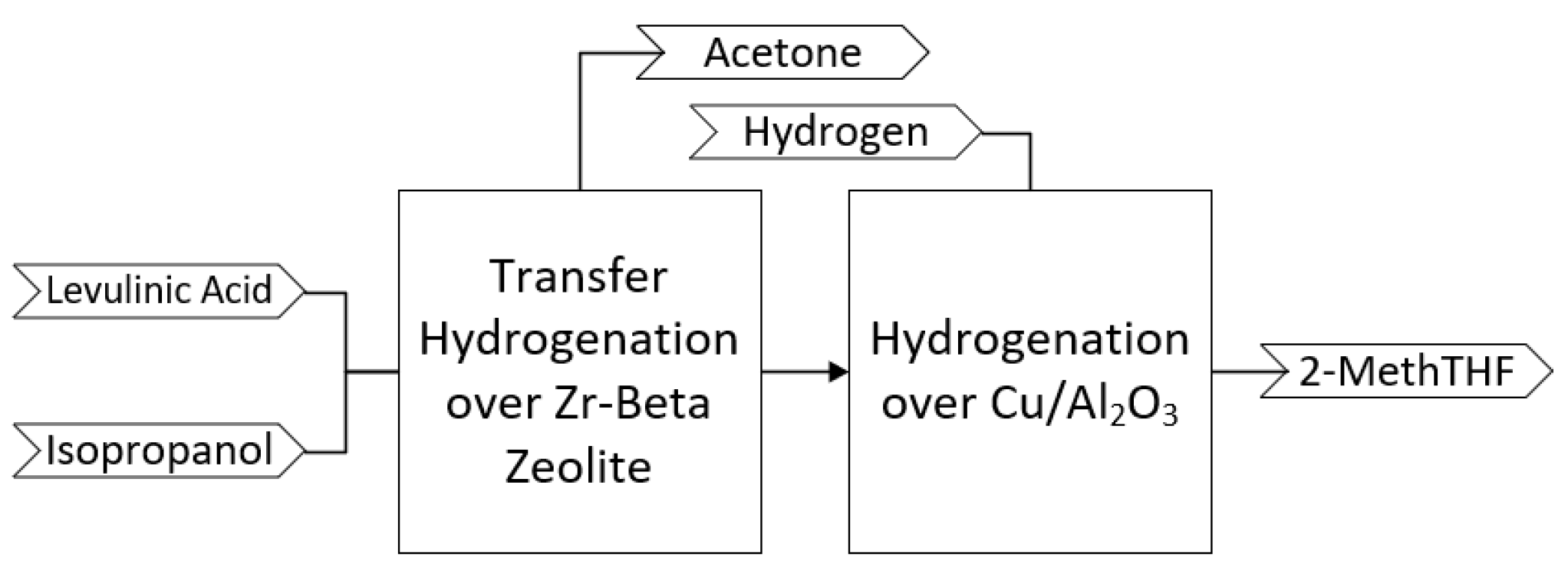
  • Translate to the continuous bench-scale (0.613 kg/h production rate) a two-step reaction pathway to convert levulinic acid into 2-methyltetrahydrofuran (2-MeTHF).
  • Determine the optimum reaction conditions for each reaction to maximize the production of 2-MeTHF through a careful study of the effects of residence time, reaction temperature, reaction pressure, and percent excess solvent used on conversion and yield in each reaction.
Several researchers have studied the conversion of levulinic acid to form γ-valerolactone (GVL) [3,8]. GVL is useful as a liquid solvent or as a transition chemical to other products [9]. From these previous studies, we have chosen to transform levulinic acid to GVL via a transfer hydrogenation reaction over a zirconium β-zeolite catalyst (Zr-Beta) [8], as shown in Figure 2. Utilizing isopropanol as the hydrogen donor, a GVL yield of 87 mol% with a selectivity of 97 mol% can be obtained. A by-product of this reaction is acetone which is formed in equivalent stoichiometric amounts as GVL when the isopropanol donates its hydrogen atom. This reaction takes place under moderate conditions: 5000 kPa, 170 °C, and a 3 h residence time. The Zr-Beta catalyst showed only a small decay in activity and can readily be regenerated via a simple in situ carbon oxidation in an air atmosphere [6].
Another proposed pathway is to react levulinic acid with formic acid. Utilizing formic acid as the hydrogen donor poses equipment complications and higher costs when moving up to industrial scales compared to isopropanol. Isopropanol has the added benefit of forming a saleable by-product, acetone. Excess isopropanol is easily recovered out of the product mix for efficient recycling.
After purifying the GVL out of the acetone and unreacted levulinic acid, it is fed to a second reactor where it undergoes a hydrogenation reaction to form 2-MeTHF over a CuO/Al2O3 catalyst [5], as shown in Figure 3. The reaction takes place using excess hydrogen gas at 1.5 MPa and 200 °C, giving yields greater than 90 mol% and a selectivity towards 2-MeTHF of 99 mol%. There are no by-products from the reaction. With a short residence time of 2 h, the reaction is attractive because of its high selectivity and yield under moderate conditions.

2. Results and Discussion

2.1. Preliminary Batch Lab-Scale Experiments—First Reaction

Preliminary runs were performed in the batch reactor system to make sure the reaction and catalyst worked before moving on to the bench-scale reactor system. Initial temperature, pressure, and residence time were determined from the literature for the initial batch lab-scale testing [8]. Reaction conditions and results for the batch lab-scale preliminary work are shown in Table 1. Yields from the preliminary batch work showed a high (93–96 mol%) selectivity towards GVL, which is consistent with previous literature [9,10]. Zr-Beta is a bifunctional catalyst containing both Lewis and Bronsted acid sites that allow for high selectivity towards GVL. The Bronsted acid sites catalyze the esterification of levulinic acid into the appropriate intermediates, which then undergo a Meerwein–Ponndorf–Verley (MPV) reduction to GVL [11]. The preliminary batch experiments showed high selectivity towards GVL, with yields of around 60–70 mol%. These yields are in line were similar lab-scale results reported in the literature using a similar catalyst [10,11] but are higher than those reported when using different catalysts [12].

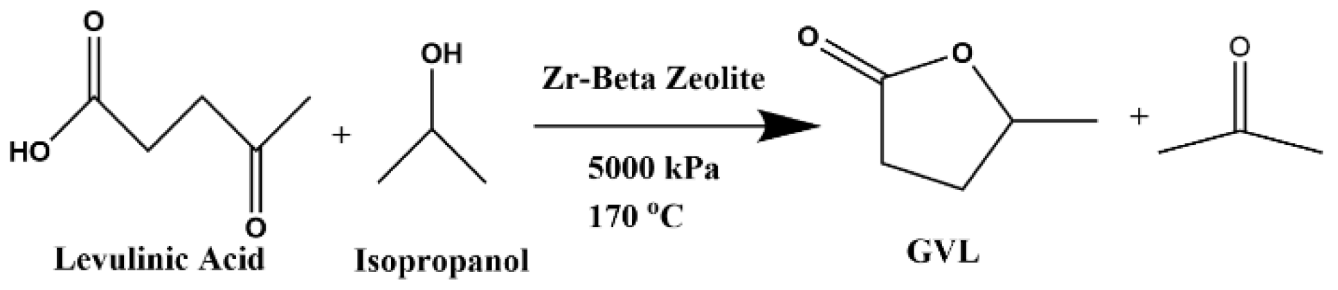
2.2. Bench-Scale Continuous Flow Conversion of Levulinic Acid to GVL

With the goal of maximizing the yield of GVL derived from levulinic acid, the effects of residence time, temperature, pressure, and excess isopropanol amount were investigated. A Box–Behnken response surface design was utilized, totaling 27 runs (see Table 1). Experimental results are summarized in Table 2. At the best conditions, 86–88 mol% yield and 98–99 mol% selectivity of GVL were achieved.
From the experimental results, it was determined that residence time was the single most important factor when maximizing the conversion of levulinic acid to GVL. Literature suggests that when converting levulinic acid to GVL using gas-phase hydrogen as the H donor, short reaction times are the tradeoff for having to operate under higher temperatures and pressures [13]. However, when utilizing an alcohol as the hydrogen donor, as in the present study, reaction conditions are milder, but longer residence times are required for optimum results. Residence times ranging from two to four hours were evaluated using the Box–Behnken design. A residence time of 2 h resulted in the lowest yield of GVL of less than 60 mol%, while a residence time of 4 h resulted in high yields of GVL at greater than 80 mol%. This is consistent with literature values that were able to obtain an 80–90 mol% yield of GVL [13,14]. A run was conducted at a residence time of 5 h, and there was no significant increase in the yield of GVL (run 29, Table 4). Yields as high as 99 mol% have been reported, but these were achieved at a smaller scale and likely had better catalyst surface area than was achieved in the present work [14].
Temperature was also found to be an important factor in maximizing the conversion of levulinic acid to GVL. At temperatures of 100 °C or below, the conversion of levulinic acid to GVL is slow, with many intermediates not fully transforming into GVL [6]. The best results were found to occur at a temperature of 170 °C. It is hypothesized that at this higher temperature, the kinetic energy of the molecules is increased, increasing the probability of proper contact [15]. Reaction temperatures above 170 °C showed no increase in conversion of levulinic acid or yield of GVL, as shown by the results at 180 °C in run 28, Table 4.
From the results of the experiments performed, it was determined that pressure was not a significant factor when maximizing yield for GVL. Traditionally conversion of levulinic acid to GVL utilized gas-phase hydrogen as the H donor. Under these conditions, pressure plays an important role in ensuring adequate contact between the reactants and the catalyst active sites [13]. A drawback of these systems is that using gas-phase hydrogen and high pressures results in the need for robust, costly reactors. When using an alcohol, such as isopropanol, the reaction is able to take place at a much lower pressure [16].
The fourth factor evaluated was the quantity of excess isopropanol fed. From the results, it was determined that the amount of excess isopropanol fed was not a significant factor in maximizing yield towards GVL within the range of 20–40 mol% excess. This is consistent with previous results of the reaction mechanism for the conversion of levulinic acid to GVL since it is not an equilibrium-driven reaction [14]. Although it is not an equilibrium-driven reaction, it is necessary to feed at least some excess isopropanol to ensure there are enough donor hydrogen ions to maximize the yield of GVL.
Notably, acetone is a by-product of this reaction and has the potential to be transformed back into isopropanol and reused or sold as a saleable by-product [13].

2.3. Batch Lab-Scale Conversion of GVL to 2-MeTHF

Similar to the first reaction, preliminary runs were performed in the batch system to ensure the reaction and catalyst worked before moving on to the bench-scale reactor system. The initial temperature, pressure, and residence time were determined from the literature for the initial batch experiments [5]. The results are shown in Table 3. The batch experimental results show a high selectivity (96–98 mol%) and yield (75–84 mol%) towards 2-MeTHF, which is consistent with previous work [5,7]. Most existing work for the conversion of GVL towards 2-MeTHF focuses on coproducing 1,4-pentanediol (1,4-PDO) and 2-MeTHF, but 1,4-PDO has fewer uses and is often transformed into 2-MeTHF [17]. In this work, we focused on conditions that can produce 2-MeTHF in high yields with high selectivity for 2-MeTHF and minimal 1,4-PDO production. As shown in Table 5, this was achieved in the batch experiments.

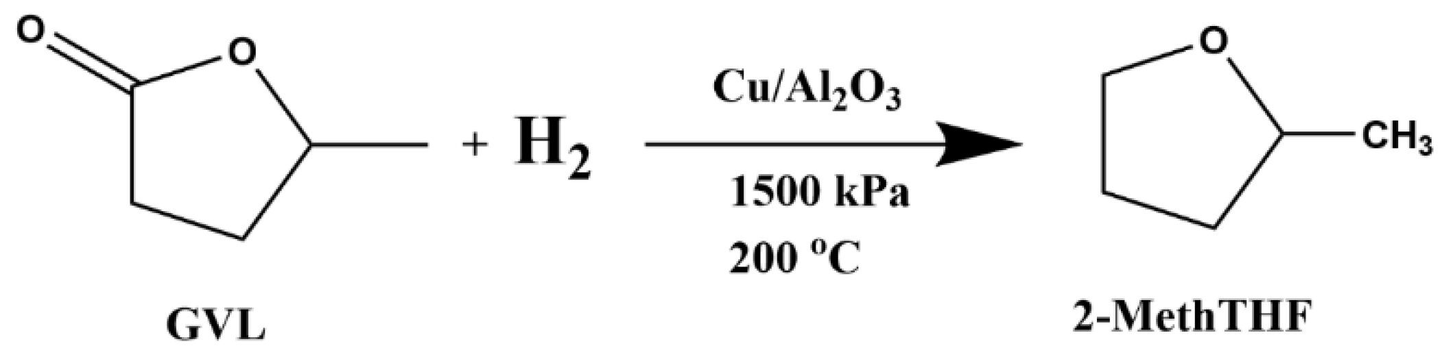
2.4. Bench-Scale Continuous Flow Conversion of GVL to 2-MeTHF

With the goal of maximizing both the yield and selectivity of 2-MeTHF derived from GVL, the effects of residence time, temperature, pressure, and excess hydrogen amount were investigated. A similar Box–Behnken response surface design as the first reaction was utilized, totaling 27 runs. The results are shown in Table 4. At the best conditions, 92–93 mol% yield and 97–98 mol% selectivity of 2-MeTHF were achieved. Similar to that of the first reaction, the factor with the greatest impact on the yield and selectivity towards 2-MeTHF was determined to be residence time. The residence time was varied from 1.5 to 2.5 h to determine the optimum conditions required to maximize yield towards 2-MeTHF. From these experimental results, a residence time of 1.5 h gave the lowest yields at less than 80 mol%. The highest yield was obtained at a residence time of 2.5 h, resulting in a yield of 93 mol%. Some literature reports yields as high as 99 mol% 2-MeTHF, but these were obtained at a smaller scale and with a catalyst that likely had a higher surface area [5,18] than the in-house synthesized catalyst used in the present study. Two additional experiments were conducted at a residence time of 3 h and the optimum pressure, excess hydrogen, and reaction temperature to bound the optimum. As shown in runs 28 and 29 of Table 5, there was no significant gain in yield or selectivity of 2-MeTHF at the longer residence time.
The second most significant factor for the formation of 2-MeTHF was found to be reaction temperature. An interesting finding was that reaction temperature affects selectivity more than yield, a finding supported by Sun et al. [5]. At the lower test point of 150 °C, the selectivity towards 2-MeTHF was lower, and more of the side product, 1,4-PDO, was formed. However, in experiments at this same temperature but longer residence times, the selectivity towards 2-MeTHF was higher. This suggests that the 1,4-PDO formed at lower reaction temperatures is eventually transformed into 2-MeTHF at the longer residence times [5,7,19]. 1,4-PDO can act as both a reaction intermediate during the transformation 2-MeTHF as well as a side product depending on the composition of the catalyst [4,5]. Certain catalyst and reaction conditions favor the formation of 1,4-PDO [20]. The optimum temperature to minimize the formation of 1,4-PDO and maximize the formation of 2-MeTHF was determined to be 200 °C. At 250 °C, selectivity towards 2-MeTHF was lower as other side reactions take place at higher temperatures (5-Hydroxy-2-pentanone and 4-Hydroxypentanol) [5].
Table 4. Continuous bench-scale reaction results for conversion of GVL to 2-MeTHF.
RunTemp. (°C)Pressure (MPa)Residence Time (hours)Excess
H2 (mol%)
2-MeTHF Yield (mol%)Standard
Error
(mol%)
2-MeTHF Selectivity
(mol%)
Standard
Error
(mol%)
12001.52.530890.3950.2
22501.52.520900.8920.9
31501.5210830.4830.7
420021.520710.9940.1
51501220851.1832.4
620011.520660.5940.4
720012.520890.2960.8
82501.5210860.7890.2
92001.51.530680.3980.1
102501.51.520660.5950.3
1120022.520881960.2
121501.52.520870.4840.4
132002210830.3930.5
142001210860.8960.2
152502220840.4920.8
162001.52.510910.3970.9
171501.5230870.8850.4
182501.5230810.3900.1
192001.5210930.5980.7
202001.5220860.4960.5
212501220790.2910.4
222001230820.9970.9
231502220832.28310
242001.5220810.1940.2
252001.51.510723.2950.4
262002230850.6940.2
271501.51.520710.7810.1
282001.5310930.7970.3
292001.5310920.5980.5
From the reaction results, it was determined that the quantity of excess hydrogen had no significant effect on the conversion or selectivity towards 2-MeTHF within the bounds of this study. This is consistent with previously published results and supports the idea that it is not an equilibrium-driven reaction [5,20]. However, sufficient hydrogen is required to ensure that all the GVL reacts. Therefore, an excess of 10 mol% gas-phase hydrogen is adequate to achieve optimum conversion.
The final factor evaluated was reaction pressure, which was varied from 1 to 2 MPa. Reaction pressure does not have a significant effect, but it does have a small effect. Since this reaction utilizes gas-phase hydrogen, increased pressure ensures proper contact between the hydrogen, the liquid phase GVL, and the active sites of the catalyst [5]. Unlike the first reaction, GVL reacts much more readily with hydrogen than levulinic acid resulting in a lower optimum reaction pressure than a gas-phase reaction of levulinic acid and hydrogen [13,21]. There was no significant effect of pressure on selectivity towards 2-MeTHF, only a small effect on the yield.

3. Methods

3.1. Reactants and Catalyst Materials

Levulinic acid (99% purity) and zirconyl chloride (98% purity) was obtained from Sigma-Aldrich, Inc. (St. Louis, MO, USA). Nitric acid (70% purity) and isopropanol (histological grade) were obtained from Fisher Scientific (Waltham, MA, USA). The hydrogen form of a β-zeolite with a SiO2/Al2O3 ratio of 300 (CP811C-300) was purchased from Zeolyst International (Kansas City, MO, USA). GVL (99% purity) was obtained from TCI America via Fisher Scientific. Sali Moldable fibrous alumina was purchased from Zircar Ceramics, Inc. (Florida, FL, USA). Compressed nitrogen and compressed hydrogen (both at 99.99% purity) were purchased from Praxair (Minneapolis, MN, USA). Copper oxide (99% purity) was obtained from Alpha Chemicals (Missouri, TX, USA). Fine aluminum oxide powder (99% purity) was purchased from Polly Plastics (Delano, PA, USA).
GVL was produced via the reaction shown in Figure 2, as described below. Excess isopropanol was removed from the reaction product mixture by evaporation at 100 kPa and 83 °C using a Yamato RE301 rotary evaporator. Once all the isopropanol was removed, the temperature was increased to 90 °C, and the GVL was evaporated under vacuum (20 kPa) until most of the GVL was removed from the reaction residue. GVL of 99% purity was acquired using this method.

3.2. Zr-Beta Preparation

Zr-Beta was produced using a modified post-synthesis approach [1,3]. The base β-zeolite was initially calcined at 600 °C for 6 h to remove any impurities. Next, the base zeolite was dealuminated in a solution of 10 M nitric acid at 80 °C for 24 h at a ratio of 50 g of zeolite per 100 mL of solution. Once dealuminated, the powders were centrifuged out of the nitric acid and washed with ultrapure water until a neutral pH was reached. Once the pH was neutral, the powder was dried overnight at 120 °C and then added to an aqueous 0.1 M ZrCl2 solution in a ratio of 10 g zeolite to 100 mL of solution. This mixture was stirred constantly at 500 rpm for 12 h at 40 °C. In the ZrCl2 solution, the dealuminated zeolite structure is impregnated with Zr, forming the Zr-Beta. Once complete, the catalyst was centrifuged out of the solution and dried overnight at 120 °C. The resulting powder was calcined for 6 h at 800 °C before being formed into pellets and recalcined.
Pelletization was performed using Sali Moldable as a binder. A 1:1 weight ratio of Sali Moldable and doped catalyst powder was used, consisting of approximately 1 kg of each. Ultra-pure water was added until a clay-like consistency was achieved, approximately 250 mL. The mixture was extruded into pellets of approximately 1.25 cm in length and dried overnight in an oven at 110 °C before being recalcined at 700 °C for 8 h. Using computer-aided scanning electron microscopy, the zirconium dopant level of the catalyst was determined to be approximately 1.1 mol% with an average pore radius of 57.1 nm.

3.3. CuO/Al2O3 Catalyst Preparation

The CuO/Al2O3 catalyst was formed by combining 54 wt% CuO powder with 46 wt% Al2O3 powder [5]. The powders were mixed using a rotary ball mill to ensure a homogenous mixture of the powders. The resulting mixture was calcined at 600 °C to remove any impurities and to form the appropriate acid sites on the catalyst structure. Once calcined, the resulting powder was formed into pellets using Sali Moldable as a binder. A 1:1 weight ratio was utilized, equaling 1 kg of catalyst powder and 1 kg of Sali Moldable. Ultra-pure water was added until a clay-like mixture was obtained, approximately 250 mL. The mixture was extruded into pellets of approximately 1.25 cm in length and dried overnight in an oven at 110 °C before being recalcined at 700 °C for 8 h. The average pore radius was determined to be 58.3 nm.

3.4. Batch Reactor

All batch reactions were conducted in a bench-scale 500 mL Parr 5500 compacted series reactor (Moline, IL, USA). The head of the reactor was mounted on a stand. The full reactor vessel was lifted up to the head and sealed with a clamp. A gas inlet on the top of the reactor was used to inject nitrogen into the reactor to displace any residual oxygen in the vapor space prior to the start of each reaction. This was performed to prevent side reactions as a result of oxidation. The gas was vented through an outlet valve to a fume hood. A rate-adjustable motor-driven stirring shaft was used to ensure complete mixing of the reactants and catalyst during each reaction. A thermocouple inside the reactor was used to monitor and provide feedback on the reaction temperature. A 4848 Parr series controller was used to control the reaction temperature at 200 °C using the readout from the thermocouple. The reactor was placed within a heating jacket with an electrical resistance heater that was altered by the controller. The internal reactor pressure was monitored with an analog gauge attached to the head of the reactor.

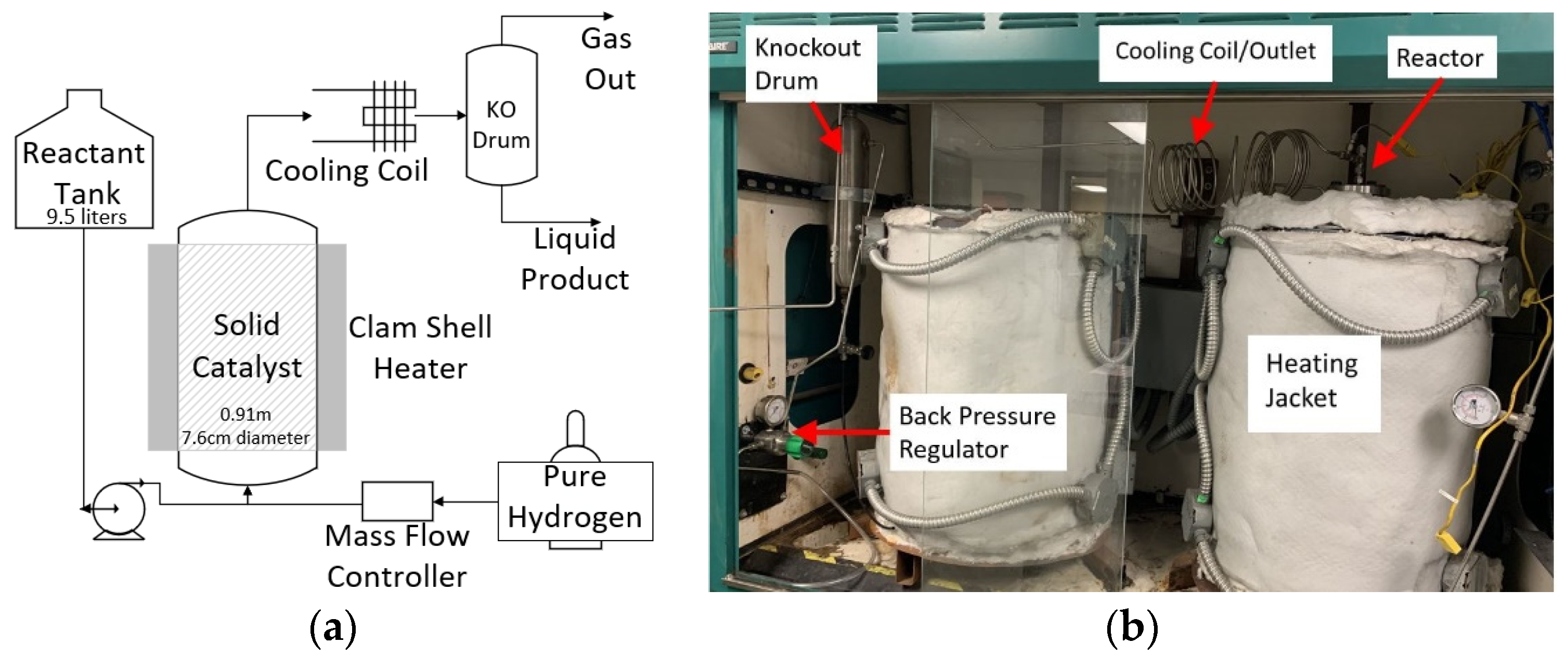
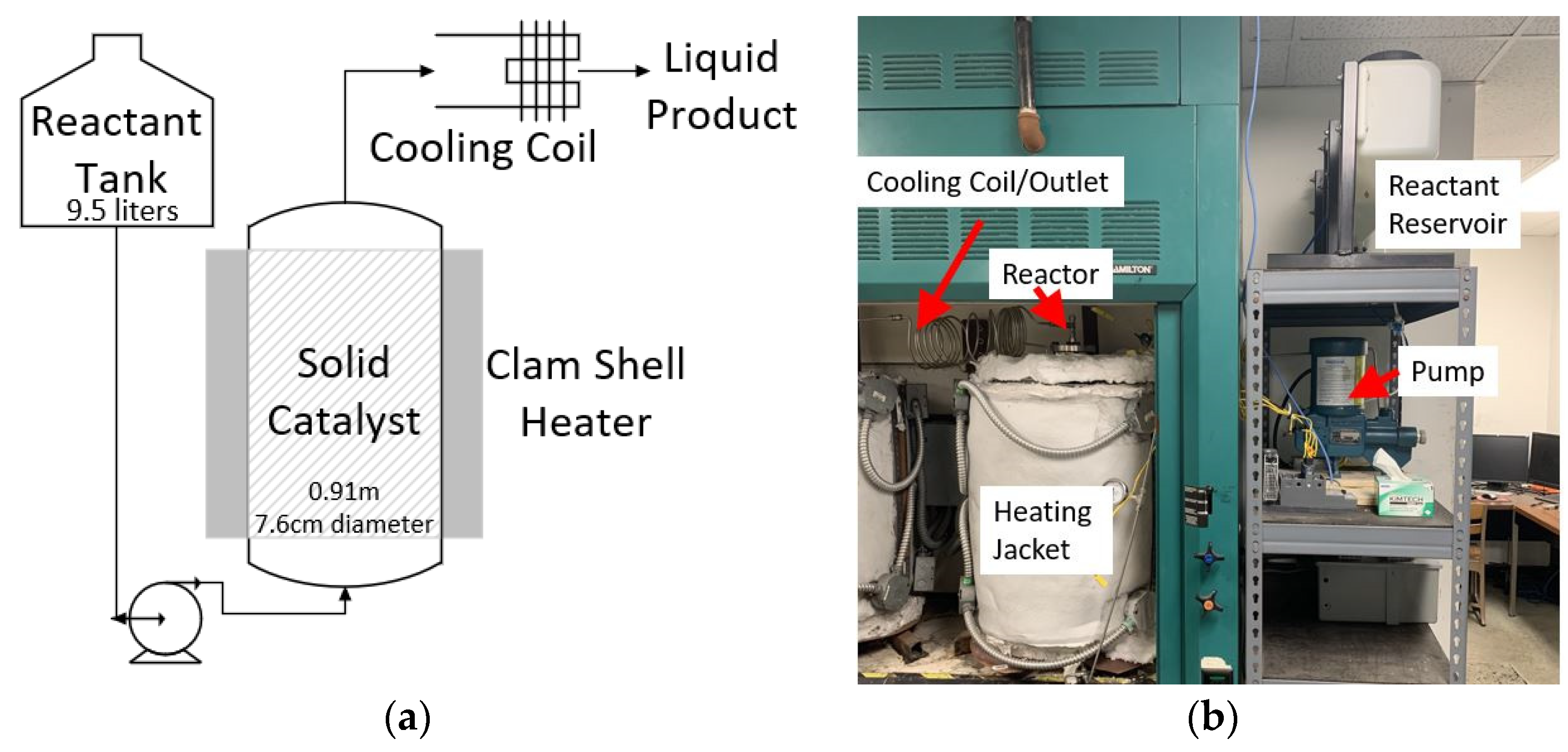
3.5. Reaction 1 Continuous Flow Bench-Scale Reactor Setup

The bench-scale continuous flow reactor for the reaction to convert levulinic acid to GVL was designed to process 1.02 kg/h of levulinic acid with 0.634 kg/h of isopropanol into a target production rate of 0.766 kg/h of GVL. The reactor configuration is shown in Figure 4. The reactor body was built using 0.91 m (3 feet) of 7.6 cm (3 inches) diameter thick wall stainless steel pipe, pressure class 600 304/304L stainless steel pipe flanges, and the appropriate gaskets from McMaster-Carr (Elmhurst, IL, USA). All bolts, nuts, and washers used for sealing the reactor were purchased from Fastenal (Grand Forks, ND, USA). A reactant reservoir tank to hold a mixture of both liquid reactants was a 9.5 L medium-density polyethylene tank from Ace Roto-Mold (Hospers, IA, USA). The solvent going into the reactor was pressurized using a positive displacement Neptune (Model: 500-A-N3) high-pressure pump. All piping, valves, pressure gauges, and fittings were purchased from Swagelok Minnesota (Chaska, MN, USA).
The reactor pressure was monitored and controlled using a back-pressure regulator from Swagelok. The reactor temperature was measured at the center of the reactor, the reactor outlet, and on the left and right side of the reactor inside the heating jacket using k-type thermocouples purchased from Omega Engineering (Norwalk, CT, USA). Data acquisition cards for reading the thermocouples were purchased from National Instruments (Austin, TX, USA). LabView™ 2018 DAQ software was used to monitor and collect temperature data for the reactor. The reactor temperature was controlled using a heating jacket with an electrical resistance heater.

3.6. Reaction 2 Continuous Flow Bench-Scale Reactor Setup

The same bench-scale reactor setup from the first reaction was utilized for the second reaction with some additions, as shown in Figure 5. A knockout drum, with a length of 30 cm and a diameter of 5.1 cm, was added to remove excess hydrogen from the liquid product after the reactor. The knockout drum was fabricated in-house from 304/304L stainless steel, with a pressure rating of 10 MPa. A 5800 Series mass flow controller from Brooks Instruments (Hatfield, PA, USA) was utilized to accurately control the flow of hydrogen into the reactor.

3.7. First-Step Batch Reaction

Batch lab-scale catalytic reaction experiments were performed to provide proof of concept of the first reaction before moving on to the continuous bench-scale reactor. Each run utilized 100 mL of levulinic acid (0.98 moles), 128 mL isopropanol (20 mol% excess), and 40 g of unpelletized Zr-Beta. The combined isopropanol, levulinic acid, and catalyst volume was kept below 500 mL to maintain safe reaction pressures as the Parr reached the operating temperature. Once the reactor was filled and sealed, it was purged of oxygen using three pressure/vent cycles from 120 kPA to atmosphere using lab-grade nitrogen. The reactor was then brought up to an initial pressure of 4000 kPa, and a 5-minute pressure check was conducted.
After the pressure check, and it was confirmed that there were no leaks, the reactor was placed in the heating jacket. When the desired operating temperature was reached (150 °C), it was held constant for 3 h. At the end of the reaction time, the reactor was removed from the heating jacket and allowed to cool using cooling water and a fan.
Once the reactor was cooled sufficiently, the reactor was depressured by routing the reactor gas through a cooling coil that was air-cooled using a fan to condense any light products with a boiling point lower than room temperature that formed before the gas was vented to a fume hood. After depressurization, the reactor was opened, and the liquid was removed. The catalyst was filtered out of the liquid by using syringe filters. The resulting liquid product was analyzed, and the recovered catalyst was dried overnight in an oven at 110 °C.

3.8. Second-Step Batch Reaction

Batch lab-scale catalytic reaction experiments were performed to provide proof of concept of the second reaction before moving on to the continuous bench-scale reactor. Each run utilized 100 mL of GVL (0.96 moles), enough hydrogen to reach pressure (1.5 MPa), and 40 g of unpelletized CuO/Al2O3 catalyst. The combined GVL and catalyst volume was kept below 500 mL to maintain safe reaction pressures as the Parr reached the operating temperature. The same procedure was utilized as the 1st-step batch reaction, except the reaction temperature was set to 200 °C.

3.9. First-Step Bench-Scale Continuous Reaction Experiments

The reactor was initially filled with approximately 2 kg of Zr-Beta pellets before sealing the top flange and inserting the thermocouple down the center of the reactor. Once the reactor was sealed and leak tested, the clamshell heating jacket was closed and energized. The reactor was initially preheated to the desired operating temperature (150 to 170 °C). While the reactor was preheating, the reactant reservoir tanks were filled with 13 L of a levulinic acid/isopropanol mixture containing 20, 30, or 40 mol% excess isopropanol. The reactants were mixed because levulinic acid forms a crystalline solid at room temperature but is soluble in isopropanol.
After filling the reactant reservoir, the pump was primed. Once the reactor reached the desired temperature and the pump was primed, the reactants were pumped into the reactor at varying flow rates corresponding to a 2, 3, or 4 h residence time. The back pressure regulator was set to maintain an operating pressure of 5000 to 5700 kPa. Once the reactor system reached a steady state (about 2–5 h depending on desired conditions), product samples were taken every 10 min for 60 min of continuous operation. Each product sample was collected by routing the sample through an air-cooled cooling coil to condense any gas-phase products that may have been produced. The exiting products were cooled to room temperature, approximately 25 °C, and collected in 50 mL glass containers.
Upon completion of each experiment, any reactants remaining in the reactor were drained and stored in 3.8 L glass bottles for analysis. Once the reactants were drained from the reactor, the catalyst was dried and recalcined in situ using atmospheric air. This was performed to eliminate possible catalyst degradation as a factor for negatively impacting yield and conversion. The reactor was then set up for the next run following the same procedure described above.
A Box–Behnken design was used to evaluate the effects of all 4 factors, totaling 27 runs. The factors varied during these experiments to determine optimum conditions are shown in Table 5. An additional experiment was conducted at the optimum pressure, residence time, and excess solvent but at 180 °C reaction temperature to ensure that the optimum reaction temperature was achieved during the DOE runs. Another parametric experiment was conducted at the optimum pressure, reaction temperature, and excess solvent amount but at 5 h residence time to ensure that the optimum residence time was achieved during the DOE runs.

3.10. Second-Step Bench-Scale Continuous Reaction Experiments

The reactor was initially filled with approximately 2 kg of pelletized CuO/Al2O3 catalyst before sealing the top flange and inserting the thermocouple down the center of the reactor. Once the reactor was sealed and leak tested, the heating jacket was closed and turned on. The reactor was initially preheated to the desired operating temperature (150 to 250 °C). While the reactor was preheating, the reactant reservoirs were filled with 13 L of GVL.
After filling the reactant reservoir, the pump was primed. Once the reactor reaches the desired temperature and the pump is primed, the reactants are pumped into the reactor at varying flow rates to ensure a 1.5, 2, or 2.5 h residence time. The hydrogen was flowed in using a mass flow controller to ensure it was fed in 10, 20, or 30 mol% excess. The back pressure regulator was set to maintain an operating pressure of 1, 1.5, or 2 MPa. Once the reactor system reached a steady state (about 1–2.5 h, depending on desired conditions), product samples were taken every 10 min for 1 h of continuous operation. The product sample was run through an air-cooled cooling coil to cool the product to 25 °C and condense any gas-phase products that may have been produced. The cooled product samples were collected in 50 mL glass vials. Upon completion of the runs, the same procedure was followed for the 1st-step reaction.
The factors evaluated for the second-step reaction optimization can be found in Table 1. A similar Box–Behnken design as the first reaction was utilized to determine the effects of the 4 factors as well as the optimum conditions. A total of 27 runs were performed. Two additional parametric experiments were conducted at the optimum pressure, reaction temperature, and excess solvent but at 3 h residence time to ensure that the optimum residence time was achieved during the DOE runs.

3.11. Analysis

Calibration curves were developed using pure standards of each reactant and anticipated product. These were used to determine the concentration of products and reactants left in the reactor outlet. Reaction products from the first reaction were quantified using high-performance liquid chromatography (HPLC, Agilent Technologies 1200 series, Santa Clara, CA, USA). Separation occurred using an Agilent Hi-Plex H column with a mobile phase of 5 mM H2SO4 at 0.6 mL/min and 40 °C. Each sample was measured using a refractive index detector (G1362A: Agilent Technologies) for 40 min.
Reaction products from the second reaction were quantified using a gas chromatography flame ionization detector (GC-FID, Agilent Technologies model 5890 FID, Santa Clara, USA). Sample injections were conducted in splitless mode at 250 °C for 0.5 min. Separation occurred on a 30 m long DB-5 column, with 0.25 mm internal diameter and 0.25 µL film thickness (J&W Scientific, Folsom, CA, USA). The temperature was programmed to hold at 35 °C for 1 min, with subsequent gradients of 10 °C/min to 105 °C and 5 °C/min to 260 °C. Analysis of experimental results was performed using Minitab™ statistical software. A total of 3 replicates were run for each sample, with 6 samples per run, which totaled 18 analyzed samples per run.

4. Conclusions

A study was performed to identify the optimum continuous reaction conditions for a two-reaction process to transform levulinic acid into 2-MeTHF. The two reactions were successfully performed in a continuous bench-scale reaction system at a feed rate of 1.02 kg/h of levulinic acid.
The optimum conditions to maximize the conversion of levulinic acid to the intermediate γ-valerolactone were determined to be 170 °C reaction temperature, 5 MPa reaction pressure, 20 mol% excess isopropanol, and a residence time of 4 h. These factors resulted in an 87 mol% yield of GVL with a selectivity of 97 mol%. The side products formed were determined to be reaction intermediates that can be recycled back into this reactor and converted into GVL. Thus, the overall yield of GVL with recycling is projected to be 95 mol%. Residence time and reaction temperature were determined to be the most significant factors affecting these two performance parameters. This result is consistent with previously published results for this reaction.
For the second reaction, the optimum conditions to maximize the conversion of GVL to 2-methyltetrahydrofuran were determined to be 200 °C reaction temperature, 1.5 MPa reaction pressure, a residence time of 2.5 h, and a feed rate of 10 mol% excess hydrogen. These factors resulted in a 93 mol% yield of 2-MeTHF with a selectivity towards 2-MeTHF of 98 mol%. The most significant factors were determined to be temperature and residence time. At low reaction temperatures, the formation of 1,4-PDO is favored but can be mitigated by increasing residence time. At temperatures of 250 °C or above, unwanted side reactions can occur.
From these results, an overall yield of 2-MeTHF from levulinic acid of 81 mol% (81 wt% inlet carbon basis) was achieved using a single pass in each reaction. This yield is projected to increase to 87 mol% (87 wt%) when the first-reaction intermediates are recovered and recycled back into the first reactor. These results are promising for commercialization. The next step is to conduct a techno-economic analysis using these results in order to guide scale-up and quantify the commercial potential of this process pathway.
2-MeTHF has an estimated global market value of USD 3.4 billion as of 2021 and is forecasted to reach USD 4.4 billion by 2030 [22]. Given that most 2-MeTHF is produced in small quantities industrially, there is a growing need for large-scale production. With a projected yearly production of 9.1 million kg/year, the projected revenue for a large-scale production facility would be approximately USD 102 million per year.

Author Contributions

Conceptualization, W.S.S.; funding acquisition, W.S.S.; investigation, E.A.P.; methodology, E.A.P. and I.M.F.; project administration, W.S.S.; resources, I.M.F.; writing—original draft preparation, E.A.P.; writing—review and editing, W.S.S. All authors have read and agreed to the published version of the manuscript.

Funding

This research was funded by the North Dakota Corn Council.

Data Availability Statement

Data is contained within the article.

Acknowledgments

The authors wish to thank Andrew Kohler, who performed the initial research to convert corn stover to levulinic acid.

Conflicts of Interest

The authors declare no conflict of interest.

References

  1. Kohler, A.; Seames, W.; Foerster, I.; Kadrmas, C. Catalytic Formation of Lactic and Levulinic Acids from Biomass Derived Monosaccarides through Sn-Beta Formed by Impregnation. Catalysts 2020, 10, 1219. [Google Scholar] [CrossRef]
  2. Toif, M.E.; Hidayat, M.; Rochmadi; Budiman, A. Glucose to Levulinic acid, a versatile building block chemical. In Proceedings of the International Conference on Science and Applied Science (ICSAS2020), Surakarta, Indonesia, 7 July 2020. [CrossRef]
  3. Mika, L.T.; Horváth, I.T. Homogeneous transition metal catalyzed conversion of levulinic acid to gamma-valerolactone. Catal. Biomass Convers. 2021, 77, 1–25. [Google Scholar] [CrossRef]
  4. Gogate, A.; Kemmer, M.; Myskewitz, E.; Stegner, L. Scoping Study for a Project to Produce Polyether Polyols from Biobased 1,4-Pentanediol; University of North Dakota Course CHE412 Report; University of North Dakota: Grand Forks, ND, USA, 2021. [Google Scholar]
  5. Sun, D.; Saito, T.; Otsuka, S.; Ozawa, T.; Yamada, Y.; Sato, S. Selective hydrogenation of γ-valerolactone to 2-methyltetrahydrofuran over Cu/Al2O3 catalyst. Appl. Catal. A Gen. 2020, 590, 117309. [Google Scholar] [CrossRef]
  6. Deng, L.; Li, J.; Lai, D.-M.; Fu, Y.; Guo, Q.-X. Catalytic conversion of biomass-derived carbohydrates into γ-Valerolactone without using an external H2supply. Angew. Chem. Int. Ed. 2009, 48, 6529–6532. [Google Scholar] [CrossRef] [PubMed]
  7. Al-Shaal, M.G.; Dzierbinski, A.; Palkovits, R. Solvent-free γ-valerolactone hydrogenation to 2-methyltetrahydrofuran catalysed by RU/c: A reaction network analysis. Green Chem. 2014, 16, 1358–1364. [Google Scholar] [CrossRef]
  8. López-Aguado, C.; Paniagua, M.; Melero, J.A.; Iglesias, J.; Juárez, P.; López Granados, M.; Morales, G. Stable continuous production of γ-valerolactone from biomass-derived levulinic acid over zr–al-beta zeolite catalyst. Catalysts 2020, 10, 678. [Google Scholar] [CrossRef]
  9. Kerkel, F.; Markiewicz, M.; Stolte, S.; Müller, E.; Kunz, W. The Green Platform Molecule Gamma-valerolactone—Ecotoxicity, biodegradability, solvent properties, and potential applications. Green Chem. 2021, 23, 2962–2976. [Google Scholar] [CrossRef]
  10. Guarinos, J.M.; Cirujano, F.G.; Rapeyko, A.; Llabrés i Xamena, F.X. Conversion of levulinic acid to γ-valerolactone over ZR-containing metal-organic frameworks: Evidencing the role of Lewis and Brønsted Acid Sites. Mol. Catal. 2021, 515, 111925. [Google Scholar] [CrossRef]
  11. Yuan, Q.; van de Bovenkamp, H.H.; Zhang, Z.; Piskun, A.S.; Sami, S.; Havenith RW, A.; Heeres, H.J.; Deuss, P.J. Mechanistic investigations into the catalytic levulinic acid hydrogenation, insight in H/D exchange pathways, and a synthetic route to D8-γ-valerolactone. ACS Catal. 2021, 11, 10467–10477. [Google Scholar] [CrossRef]
  12. Damayanti, A.P.; Dewi, H.P. Selective hydrogenation of levulinic acid to γ-valerolactone using bimetallic Pd-Fe catalyst supported on titanium oxide. IOP Conf. Ser. Mater. Sci. Eng. 2020, 980, 012013. [Google Scholar] [CrossRef]
  13. González, G.; Area, M.C. An overview of the obtaining of biomass-derived gamma-valerolactone from levulinic acid or esters without H2 supply. BioResources 2021, 16, 8417–8444. [Google Scholar] [CrossRef]
  14. Dutta, S.; Yu, I.K.M.; Tsang, D.C.W.; Ng, Y.H.; Ok, Y.S.; Sherwood, J.; Clark, J.H. Green synthesis of gamma-valerolactone (GVL) through hydrogenation of biomass-derived levulinic acid using non-noble metal catalysts: A critical review. Chem. Eng. J. 2019, 372, 992–1006. [Google Scholar] [CrossRef]
  15. Hengne, A.M.; Kadu, B.S.; Biradar, N.S.; Chikate, R.C.; Rode, C.V. Transfer hydrogenation of biomass-derived levulinic acid to γ-valerolactone over supported ni catalysts. RSC Adv. 2016, 6, 59753–59761. [Google Scholar] [CrossRef]
  16. Omoruyi, U.; Page, S.; Hallett, J.; Miller, P.W. Homogeneous catalyzed reactions of levulinic acid: To γ-valerolactone and beyond. ChemSusChem 2016, 9, 2037–2047. [Google Scholar] [CrossRef] [PubMed]
  17. Chia, M.; Dumesic, J.A. Liquid-phase catalytic transfer hydrogenation and cyclization of levulinic acid and its esters to γ-valerolactone over metal oxide catalysts. Chem. Commun. 2011, 47, 12233. [Google Scholar] [CrossRef] [PubMed]
  18. Liu, Q.; Zhao, Z.; Arai, M.; Zhang, C.; Liu, K.; Shi, R.; Wu, P.; Wang, Z.; Lin, W.; Cheng, H.; et al. Transformation of γ-valerolactone into 1,4-pentanediol and 2-methyltetrahydrofuran over zn-promoted Cu/Al2O3 Catalysts. Catal. Sci. Technol. 2020, 10, 4412–4423. [Google Scholar] [CrossRef]
  19. Obregón, I.; Gandarias, I.; Ocio, A.; García-García, I.; Alvarez de Eulate, N.; Arias, P.L. Structure-activity relationships of Ni-Cu/Al 2 o 3 catalysts for γ-Valerolactone conversion to 2-methyltetrahydrofuran. Appl. Catal. B Environ. 2017, 210, 328–341. [Google Scholar] [CrossRef]
  20. Pothu, R.; Challa, P.; Rajesh, R.; Boddula, R.; Balaga, R.; Balla, P.; Perugopu, V.; Radwan, A.B.; Abdullah, A.M.; Al-Qahtani, N. Vapour-phase selective hydrogenation of γ-Valerolactone to 2-methyltetrahydrofuran biofuel over silica-supported copper catalysts. Nanomaterials 2022, 12, 3414. [Google Scholar] [CrossRef] [PubMed]
  21. Du, X.-L.; Bi, Q.-Y.; Liu, Y.-M.; Cao, Y.; He, H.-Y.; Fan, K.-N. Tunable copper-catalyzed chemoselective hydrogenolysis of biomass-derived γ-valerolactone into 1,4-pentanediol or 2-methyltetrahydrofuran. Green Chem. 2012, 14, 935. [Google Scholar] [CrossRef]
  22. 2-Methyl-Tetrahydrofuran-Market Size, Share, Analysis & Forecast. Verified Market Research. 2023. Available online: https://www.verifiedmarketresearch.com/product/2-methyl-tetrahydrofuran-market/ (accessed on 29 March 2023).
Figure 1. Basic process scheme.
Catalysts 13 00972 g001
Figure 2. GVL production from levulinic acid.
Catalysts 13 00972 g002
Figure 3. 2-MeTHF production from GVL.
Catalysts 13 00972 g003
Figure 4. First-step reactor configuration: (a) schematic and (b) photo.
Catalysts 13 00972 g004
Figure 5. Second-step reactor configuration: (a) schematic and (b) photo.
Catalysts 13 00972 g005
Table 1. Preliminary batch scale results for transformation of LA to GVL.
Temp. (°C)Pressure (MPa)Reaction Time (hours)Excess C3H8O mol%GVL Yield (mol%)Selectivity (mol%)
15053206894
15053206793
15053207096
Table 2. Results from conversion of LA to GVL runs.
RunTemp (°C)Pressure (MPa)Excess
C3H8O
(mol%)
Residence Time
(hours)
GVL Yield (mol%)Standard
Error
(mol%)
GVL Selectivity
(mol%)
Standard
Error
(mol%)
11705.35203770.2940.1
21605302540.5910.6
31505.35403710.1950.2
41505.35304831.5960.9
51605.7302530.4900.1
61505.7303690.9940.7
71605.35303730.3930.5
81705.35403760.3950.9
91605.35303710.8940.1
101705204870.4980.2
111705.7303740.2950.8
121605.7304830.9980.4
131605.7403700.7940.2
141605403690.5930.6
151505.35302520.6890.3
161605304840.1960.3
171605.7203682.1920.9
181605.35404830.3980.5
191705.35302570.4870.1
201705.35304860.6970.7
211505303700.2940.3
2216052037118941.1
231505.35203710.4930.3
241605.35402550.7900.1
251605.35202580.5880.7
261605.35204850.4960.4
271605.35303720.7950.6
281805204860.4980.3
291705205880.2970.1
Table 3. Preliminary batch work for conversion of GVL to 2-MeTHF.
Temp (°C)Pressure (MPa)Reaction Time (hours)Excess H2 (mol%)2-MeTHF Yield (mol%)Selectivity (mol%)
2001.51.5207598
2001.52208496
2501.51.5207797
Table 5. Factors evaluated for 1st-step optimization.
ReactionTemperature (°C)Pressure (MPa)Residence Time (hours)Excess H Donor (mol%)
Levulinic to GVL150, 160, 1705, 5.72, 3, 4, 520, 30, 40
GVL to 2-MeTHF150, 200, 2501, 1.5, 21.5, 1, 2, 2.510, 20, 30
Disclaimer/Publisher’s Note: The statements, opinions and data contained in all publications are solely those of the individual author(s) and contributor(s) and not of MDPI and/or the editor(s). MDPI and/or the editor(s) disclaim responsibility for any injury to people or property resulting from any ideas, methods, instructions or products referred to in the content.

