Article

Fuel Consumption and Emission Reduction for Non-Road Diesel Engines with Electrically Heated Catalysts

1
Korea Automotive Technology Institute, Cheonan-si 31214, Republic of Korea
2
Sejong Industrial, Yongin-si 16950, Republic of Korea
*
Author to whom correspondence should be addressed.
Catalysts 2023, 13(6), 950; https://doi.org/10.3390/catal13060950
Submission received: 21 April 2023 / Revised: 22 May 2023 / Accepted: 22 May 2023 / Published: 30 May 2023

Abstract

:
In this study, an exhaust system compliant with future regulations was developed for a non-road 110PS engine with a Tier-4f aftertreatment system, and the emission characteristics of the engine were investigated in the non-road transient mode (NRTC). For the system to comply with future exhaust regulations, a DPF was installed, and an electrical heated catalyst (EHC) device was installed to manage exhaust gas temperature. The emission characteristics of exhaust gas were examined according to the power and applied duration of EHC, and the effects of catalyst coating and the urea water solution (UWS) injection map on NOx reduction, NH3 slip, and N2O emissions in NRTC mode were investigated. The application of a 4 kW class EHC system enables the lowering of the injection starting temperature of the UWS, as reliable gas heating (heating duration control) is guaranteed. When the injection starting temperature (based on the SCR inlet temperature) was set to 150 °C, NSR map, (III) in conjunction with the operation of the EHC, effectively achieved significant NOx reduction in NRTC mode without deposit and wetting occurring in the mixer and exhaust pipe. Regarding changes in EHC power from 3 kW to 4 kW, it was observed that a NOx reduction of 0.05 g/kWh occurs in the cold NRTC mode, but in the hot NRTC mode, it was found that the relative decrease in the UWS is due to the increased NO2 conversion efficiency as a result of the oxidation catalyst, making 3 kW more advantageous. Furthermore, due to the increase in NO2 concentration caused by the oxidation catalyst and the increase in the low-temperature injected UWS, NH4NO3 was formed, which resulted in an increase in PM emissions and a significant increase in N2O emissions around an exhaust temperature of 250 °C. When the EHC power was set to 3 kW and the volume of oxidation catalyst and the amount of UWS injection were adjusted, applying EHC in the NRTC mode resulted in an additional NOx reduction of 58.6% and 88.4% in cold and hot modes, respectively, compared with not using EHC, with a fuel penalty of approximately 1.67%, while limiting the peak concentrations of N2O and NH3.

1. Introduction

Commercial and non-road vehicles typically use diesel engines, which generally have higher power, better fuel efficiency, and lower carbon dioxide emissions compared with gasoline engines. However, diesel engines also have high levels of particulate matter (PM) and nitrogen oxide (NOx) emissions due to the coexistence of local fuel-rich areas and high-temperature flame zones within the combustion chamber [1,2]. To solve these problems, the engine itself has been improved, and technologies such as in-cylinder combustion using high-pressure multi-fuel injection [3,4] and exhaust gas recirculation (EGR) have been developed [5,6,7]; however, advancements in engine technology alone cannot be enough to meet increasingly stringent exhaust regulations. Therefore, aftertreatment systems for PM reduction and NOx reduction are additionally applied and now have become essential devices. The PM emissions from diesel engines have been drastically reduced with the development of the diesel particulate filter (DPF) to meet the Euro-4 emission regulations, and DPFs are now applied to almost all diesel vehicles [8,9], which are equipped with PM sensors for monitoring DPF failures [10]. For PM reduction, the aforementioned DPF is a reliable technology, but for NOx reduction, various catalytic systems such as lean NOx trap (LNT) [11,12], hydrocarbon selective catalytic reduction (SCR) [11,13], and urea SCR [11,14,15,16,17] have been proposed depending on the exhaust conditions and various operational characteristics. Under current exhaust regulations (Euro-6 and Tier-4), LNT and SCR systems or a combination of these two catalysts are used for passenger cars [11,18], while urea-SCR systems, which can guarantee a reliable reduction in an appropriate exhaust temperature window without fuel penalty and complex operation, are widely used in commercial and non-road vehicles [18,19,20,21]. Future strengthened emission regulations are expected to demand additional reduction in exhaust emissions in real driving environments and across the entire operating range of vehicle engines. Therefore, the development of NOx reduction technologies related to engine operation has become a key aspect to meet exhaust regulations [22,23].
The emission regulations of non-road engines were mainly developed according to the EU Stage regulation and the U.S. Tier regulation schedules. Currently, the Tier-4f emission regulations in North America do not include restrictions on the number of particulate matter (PN-particle number), so the use of diesel particulate filters (DPFs) is not common. Instead, the regulations are addressed by strengthening the function of diesel oxidation catalysts (DOCs). On the contrary, in the case of EU stage V, appropriate-sized DPFs are generally applied to meet the regulation of particle number. Additionally, since the NOx emission standard significantly changes at the engine power boundary of 56 kW, engines with a power greater than this boundary are addressed by applying urea-SCR, while power outputs lower than this boundary are addressed by improving in-cylinder combustion through exhaust gas recirculation (EGR) [19,24]. The upcoming non-road regulations, such as CARB (Tier 5) and EU (Post stage V), will focus on strengthening NOx emission regulations under actual operating conditions. Depending on the engine power, they are expected to require a reduction in PM and NOx emissions from 50 to 90% compared with current emission levels. Therefore, the application of NOx reduction technology to entire engine operating points is recognized as a key technology to meet future regulations [25,26].
The engine evaluation modes used on non-road vehicles are the steady mode, NRSC (non-road steady cycle), and the transient mode, NRTC (non-road transient cycle). The NRSC mode is a mode that evaluates the engine performance in the steady state, and depending on the operating range, it has a constant and appropriate exhaust temperature condition for the catalytic converter to function properly. On the other hand, the NRTC mode, which is a transient mode, calculates the mode emission results by adding the emissions of cold start 10% and hot start 90% for the EU-Stage V regulation (cold 5% + hot 95% for U.S. cases) [19,21,24]. Therefore, when considering future exhaust regulations, it is important to reduce exhaust gas emissions, especially NOx, in the transient mode. In the cold start NRTC mode, which accounts for 10% of NRTC NOx emissions, it is important for the rapid exhaust gas temperature to rise up to the light-off temperature of the catalyst, while in the hot mode, which accounts for 90% of the total emissions, it is important to precisely control the UWS injection to maintain high NOx reduction efficiency while minimizing NH3 slip and N2O formation due to side reactions [21,27,28,29].
The temperature of the SCR catalyst is a critical factor for effective NOx reduction. Especially in the NRTC cold mode of non-road engines, it takes about 400~500 s for the SCR catalyst temperature to reach 200 °C, and considering that this period accounts for 1/3 of the entire mode, it has a significant impact on the NOx emission results of the entire mode [14]. Therefore, for an additional reduction in NOx, the utilization of the SCR catalyst in the early stage of the NRTC mode is important, and rapid heat up of the exhaust temperature is important for this purpose. Various methods are being investigated to increase the exhaust gas temperature for rapid activation of the catalyst in the cold mode, such as the post-injection in-cylinder method [30,31,32], mini or proper type burners [30,33], and electrical heaters [18,30,34], among which the electrical heated catalyst (EHC)-based heating method is actively being considered to reduce exhaust emissions from small to medium-sized engines [22,35,36,37], due to its advantages of fast response time, system compactness, and independence from engine operation, taking into account electrification (48 V, HEV, PHEV, etc.) of various mobilities (Table 1).
In this study, an exhaust system compliant with future regulations was developed for a non-road 110PS engine with a Tier-4f aftertreatment system, and the emission characteristics of the engine were investigated in the non-road transient mode (NRTC). For the system to comply with future exhaust regulations, a DPF was installed, and an electrical heated catalyst (EHC) device was installed to manage the exhaust gas temperature. The EHC was designed, taking into account the exhaust flow rate and temperature in the cold NRTC mode, and applied as an integrated catalyst upstream of the DOC. The emission characteristics of the exhaust gas were examined according to the power and applied duration of the EHC, and the effects of catalyst coating and the UWS injection map on NOx reduction, NH3 slip, and N2O emissions in the NRTC mode were investigated.

2. Result and Discussion

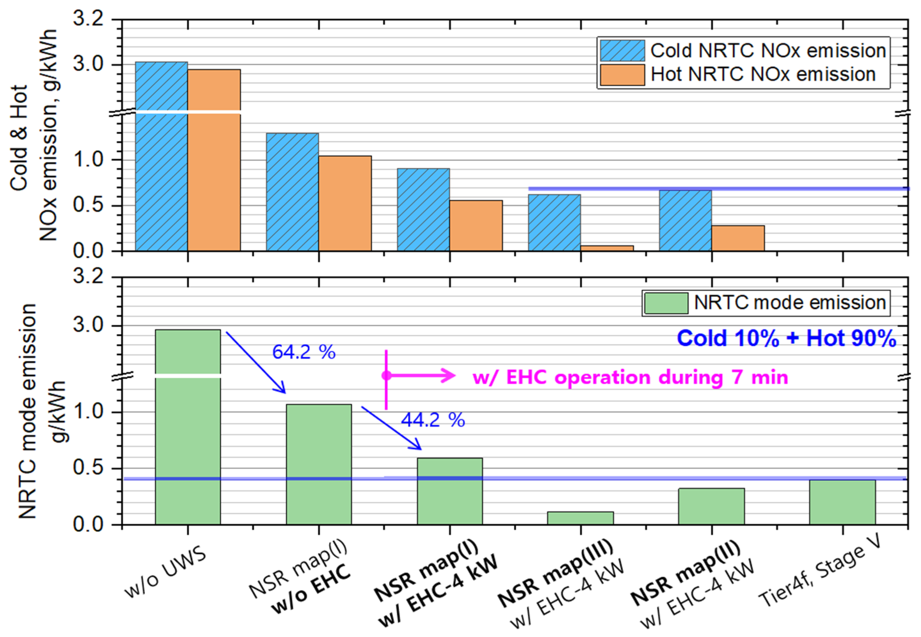
2.1. The Effect of UWS Injection Start Temperature and NSR Map on NOx Emissions

The injection start temperature of the UWS has significant importance for improving the reduction efficiency in cold-start NRTC. Generally, the UWS rapidly evaporates moisture above 135 °C, and at exhaust temperatures above 180 °C, urea thermolysis occurs, producing reducing agents NH3 and HNCO. Subsequently, in the catalyst layer, HNCO is hydrolyzed at 200~250 °C, producing additional NH3, which generates the reducing agent necessary for the SCR reaction [38]. Therefore, for the initial thermolysis reaction to occur without deposits, it is necessary to set the injection starting temperature above the thermolysis temperature. Figure 1 shows the exhaust temperature of each part of the aftertreatment catalyst before and after operating the EHC at 7 min and 4 kW in the cold NRTC mode. When examining the SCR catalyst inlet temperature profile without EHC, it was possible to inject the UWS when the time reached 450 s after the mode started and a temperature of 200 °C was reached where sufficient thermolysis occurred. This makes it difficult to achieve improved exhaust regulation.
When operating the EHC at 4 kW at the start of the mode, it can be observed that the time to reach the SCR inlet temperature criterion of 200 °C was reduced to 320 s, which is 130 s shorter than without the EHC. Moreover, in the DPF outlet condition, which is the UWS injection location, it changed significantly to about 140 s from mode start. Therefore, in this study, NRTC mode emissions were analyzed by constructing an NSR map based on three injection starting temperatures of the UWS linked with the EHC operation:
  • One was to set the injection start temperature to 200 °C based on the DPF outlet exhaust temperature, which is equivalent to an SCR inlet temperature of 150 °C, and create an NSR map (Figure 2-(III)).
  • The second was to set the injection start temperature to 175 °C at the SCR inlet (Figure 2-(II)).
  • The third was to set the injection start temperature based on 200 °C (Figure 2-(I)).
Figure 2 shows three NSR UWS injection maps created based on the SCR inlet exhaust temperature. As can be seen in the figure, the NSR map was set based only on changes in exhaust gas temperature, without any changes according to SV, in order to observe the influence near the start of the injection.
Figure 3 shows the temperature distribution, UWS injection amount, and NOx emission results for the NRTC cold and hot modes according to time when applying the NSR maps in Figure 2. As can be seen in the figure, when the EHC was activated, the SCR inlet temperature increased, and for NSR map (I), the time when the UWS injection was possible shifted to around 360 s, which was originally 480 s. As a result, the NOx emissions decreased, and it was shown that NOx was hardly emitted from an SCR inlet temperature of around 250 °C.
NSR maps (II) and (III), which were adjusted for the timing of the UWS injection in conjunction with the EHC operation, showed a reduction in NOx emissions in the NRTC cold mode due to the faster initiation of the UWS at 260 and 130 s, respectively. In particular, a significant decrease in NOx emissions was observed in hot NRTC mode compared with NSR map (I). Figure 4 is a summary of the NRTC mode results. Under the condition without the UWS injection, 3 g/kWh of emissions were observed in both the cold and hot modes. At this time, when the UWS was injected with NSR map (I), it showed an emission of 1.07 g/kWh with a 64.2% reduction in NOx emissions. Considering that the target engine was a Tier 4 engine, the NOx emissions in NRTC mode were high. These results were attributed to the increase in the exhaust system between the engine and aftertreatment system, an increase in preheating time of SCR catalyst due to DPF installation, and an increase in NO2 conversion due to the oxidation catalyst. When applying the initial 7 min cold and hot modes of a 4 kW EHC separately under the same NSR map (I), the UWS injection was advanced due to the increase in exhaust gas temperature compared with the case where the EHC was not operated, resulting in an additional 44.2% reduction in NOx emissions (0.596 g/kWh). As the operation of the EHC guarantees an increase in exhaust gas temperature at the UWS injection location, NSR map (III), which increased the injection quantity considering the increase in UWS usage due to NO2 generation by DOC and DPF and set the UWS injection start temperature to 150 °C with EHC operation, was able to reduce NOx emissions to 0.120 g/kWh (cold: 0.621 g/kWh, hot: 0.065 g/kWh). When examining the mode-specific NOx reductions, it can be seen that the emission in the hot mode decreased significantly compared with that in the cold start mode. This is because in the case of the cold start mode, although the UWS supply was provided by greatly advancing the injection start time due to the EHC, the slow increase in the temperature of the entire SCR catalyst limited the NOx reduction efficiency of the catalyst. The result of NOx reduction in the cold start NRTC for NSR map (II) with a UWS injection start temperature of 175 °C showed a similar level of reduction to that of NSR map (III); this evidence supports our explanations.

2.2. The Effect of Electrical Heating Power and Duration on NOx Emissions

We investigated the effects of the electrical heating power and heating duration in the cold/hot NRTC mode on NOx emissions using NSR map (III) at an injection start temperature of 150 °C. Figure 5a shows the exhaust gas temperature profiles and NOx emission results in the cold NRTC mode when supplying 3 kW and 4 kW of electrical power from the initial key-on for 7 min. When supplying 4 kW of heating power, the exhaust temperature was about 5 °C higher at 200 s with an SCR inlet temperature of 150 °C compared with a supply of 3 kW of heating power, and it showed about 12 °C higher temperature at around 300 s and 200 °C. When examining the NOx emission profile of the mode at the initial stage (Figure 6-NRTC cold start), a significant difference in reduction efficiency was observed between 200 and 250 s around the SCR inlet temperature of 150 °C. Afterward, at temperatures above 200 °C, the difference became smaller, and emissions showed a nearly identical profile. This is because the increased NO2 conversion (NO + 1/2O2→NO2) by the oxidation catalyst around the SCR inlet temperature of 200 °C corresponds to around 300°C in the DOC and c-DPF, resulting in a relative reduction in UWS injection quantity due to an increase in NO2 concentration. In the NRTC cold mode, 4 kW heating resulted in an additional reduction of about 0.05 g/kWh in NOx emissions compared with 3 kW heating. Figure 5b shows the temperature profiles and NOx emissions according to changes in heating power and heating duration in the NRTC hot mode. As can be seen from the figure, in the hot mode, a lower NOx emission result was observed at 3 kW heating power compared with 4 kW. This can be seen by examining the NOx emission characteristics over time in the NRTC hot start mode, as shown in Figure 6. Examining the NOx concentration profile of the 7 min heating period, it can be seen that 3 kW heating showed a lower emission characteristic up to 265 s. As explained in the cold mode, this is because the relative UWS quantity decreased due to the increase in NO2 concentration by the DOC and c-DPF. Furthermore, it was confirmed in the NO and NO2 emission profiles in Figure 7 that significant unremoved NO2 emissions were observed in the case of the 4 kW heating.
As the heating duration in hot mode was reduced, the NOx emissions gradually increased and approached the emission value (~0.3 g/kWh) without heating. As shown in Figure 5b, in the case of 3 min heating, the SCR inlet temperature did not decrease immediately after 180 s due to the heat capacity of the DPF substrate and showed a temperature profile similar to that of the 7 min heating case until 265 s. As a result, the SCR inlet temperature was maintained at over 200 °C, but the emission increased from 0.075 g/kWh to 0.155 g/kWh (increased NOx emissions in the range of 230 s to 500 s in Figure 7) due to the decrease in activity caused by the temperature difference of about 50 °C compared with 7 min heating.
Figure 8 shows the NRTC mode results according to the heating duration and power change in the hot start mode when the heating duration was 7 min at cold start mode. As explained previously, when the injection map (NSR map (III)) is the same, changing the heating power to 3 kW and 4 kW did not have a significant impact on NOx emissions. On the other hand, in the case of the cold start mode, the heating duration must be maintained for at least 300 s to maintain an SCR inlet temperature above 200 °C, and it was found that NOx emissions change significantly depending on the heating duration of the hot start mode. As this study aims for emissions at half the level of Stage V regulations, it was found that in order to achieve this goal, a minimum of 5 min of heating duration was required for the cold start mode with 3 kW of power, which has low energy consumption per unit time, and a minimum of 3 min of heating duration was required for the hot start mode.

2.3. NH3, N2O, and PM Emission According to Oxidation Catalysts

The oxidation catalyst coating was performed on the EHC metal substrate used in this study. The oxidation catalyst was coated with 40 g/ft3 of Pt-Pd/Al2O3 and was installed at the same location (upstream of the previous DOC) in the aftertreatment device using the previous EHC. Figure 9 shows the NOx emission results when using NSR map (III) and reducing the heating duration to 5 min in the cold NRTC mode (maintaining up to 300 °C of DOC inlet) to suppress excessive NO2 concentration caused by excess EHC heating. As shown in the figure, it can be observed that there is almost no NOx reduction during the heating period of 200 s to 300 s when the EHC metal substrate is coated, which is unlike the case when it is not coated. Furthermore, even with sufficient temperature in the latter part of the mode after heating completion, as opposed to the case without coating on the EHC metal substrate, 50~100 ppm of NOx emission occurs. This can be inferred as a result of relative UWS shortage due to excessive NO2 generation by the oxidation catalyst.
The NRTC cold start results when the UWS injection quantity was increased by 5% overall in NSR map (III) are shown in Figure 10. When the UWS injection amount was increased, NOx reduction was achieved overall in the mode, and especially around 200~300 s and up to 300 °C of the DPF outlet temperature, significant NOx reduction was achieved in response to the increase in injection amount. However, it can be seen that the reduction amount is not significant after 600 s. Moreover, around 700 s, N2O emission showed a peak value of about 20 ppm. This is attributed to the increase in NH4NO3 formation due to the increase in NO2 conversion efficiency caused by excessive use of the oxidation catalyst. The increased NO2 formed NO3- by Cu(OH)+ on the SCR catalyst and the NH4NO3 formed by combining the injected/absorbed NH3 with NO3- resulted in N2O emission due to the decomposition of NH4NO3 with increasing exhaust temperature [39,40,41,42].
As mentioned previously, the UWS injected at low temperature forms NH4NO3 and is deposited on the SCR surface, and is sometimes emitted into the exhaust pipe due to fluctuations in exhaust flow [38,43]. This showed that, despite the presence of a wall flow diesel particle filter capable of effectively removing PM generated by the engine, the PM emissions resulted in non-compliance with the Stage V PM regulation due to the oxidation catalyst and the UWS injection. Furthermore, when the UWS injection quantity was increased by 5% overall in NSR map (III) as shown in Table 2, it resulted in a significant increase in PM emissions in the hot mode.
Therefore, in order to minimize the increase in PM due to excessive NO2 production, a decrease in SCR reaction rate, and the generation of N2O caused by the high NO2 conversion effect of the oxidation catalyst due to EHC heating, the existing ceramic DOC was removed and the aftertreatment system was reconstructed. Figure 11 shows the result of heating the metal substrate oxidation catalyst of the EHC with a heating power of 3 kW for 6 min in the cold NRTC mode, excluding the existing ceramic DOC. As the DOC catalyst was removed, the SCR inlet temperature increased by about 15–20 °C and the decrease in NO to NO2 conversion rate resulted in a reduction in NOx emissions during the EHC heating phase in the cold mode and the elimination of unreacted NO2 in the latter part of the mode, even when using NSR map (III) for the UWS injection. It showed a significant reduction in PM emission, which is inferred to be due to the decrease in NH4NO3 formation as a result of the reduction in NO2 during the heating phase. However, N2O emissions decreased compared with the previous case at exhaust temperatures above 250 °C, but were still emitted at a peak value of about 8 ppm.
Figure 12 shows the exhaust emission results of the NRTC mode when heating for 6 min at cold start and 3 min at hot start with 3 kW heating power using the EHC metal DOC and NSR map (III). As shown in the figure, the cold and hot start NOx emissions decreased by 17.8% and 10.4%, respectively, compared with the NOx emissions with 7 min heating without a catalyst coating on the EHC, resulting in emission levels of 0.534 g/kWh and 0.121 g/kWh, respectively, due to the increase in exhaust temperature caused by the removal of the existing DOC and the application of the EHC metal DOC. This resulted in a 59.5% decrease compared with the Stage V regulation. At this point, the peak values of N2O and NH3 slip were found to occur around 800–1000 s and were larger in hot start than in cold start. As previously mentioned, the high peak value of N2O around 900 s appears to be a typical result of the decomposition of NH4NO3 formed at low temperatures by the increase in exhaust temperature, resulting in the generation of N2O. Furthermore, at a position similar to where N2O was generated during the hot start mode, NH3 adsorbed on the catalyst was desorbed, resulting in NH3 slip at a level of 7 ppm. The resulting N2O and NH3 emissions are influenced by the urea and nitrate accumulation due to the UWS injection for the NOx reduction at low temperatures, and the NOx emission target setting at the temperature window where the SCR reaction is active. Therefore, in order to reduce the emissions of N2O and NH3, independent controls of the UWS injection in low exhaust temperature or injection quantity according to operating conditions are required under conditions where heating duration or control are guaranteed, such as EHC, and it is necessary to limit NOx reduction targets of the catalyst to exhaust temperature. The PM emission was reduced significantly due to the removal of the additional PM (UWS deposit, NH4NO3, etc.) generated downstream of the DPF by applying an appropriate DOC size, resulting in emission levels much lower than those required by Stage V.

2.4. Equivalent Fuel Penalty

The emission reduction characteristics of EHC were analyzed in NRTC mode by applying it to a 110PS, 4 L common rail diesel engine for non-road vehicles. At the existing Tier 4 level, DPF application significantly reduced the particle number and weight of PM, and EHC application reduced NOx by 59.5% (from 0.4 g/kWh to 0.162 g/kWh). At this time, the energy used for EHC in cold and hot NRTC mode was 0.3 kWh and 0.15 kWh, respectively. Considering the BSFC in each mode, which is 0.261 kg/kWh and 0.253 kg/kWh for cold and hot modes, respectively, converting the energy used for EHC into fuel yields the results are shown in Table 3. The energy consumed by using 3 kW EHC for 6 min in the cold NRTC mode corresponds to 76 g of fuel, resulting in a fuel penalty of approximately 3.01%. In the case of the hot NRTC mode, using EHC for 3 min consumed fuel equivalent to 38 g, resulting in a fuel penalty of 1.53%. This is attributed to the appropriate EHC heating duration and adjustment of the NSR map. An additional NOx reduction can be effectively achieved by further optimization, such as intake throttling and EHC preheating logic, if applied in conjunction with EHC.

3. Experimental Setup

3.1. Engine and Aftertreatment System

The engine used in this study is an in-line 4-cylinder common-rail 3.9-L engine (Hyundai, D4GB) with a maximum output of 110 horsepower and is a Tier-4 exhaust level engine applied to a forklift. High-pressure EGR (HP-EGR) system is applied, and diesel oxidation catalysts (DOC, Pt-Pd coated with 1:2 ratio on Al2O3 support) and urea SCR (Cu/SSZ-13) are applied to meet Tier-4 emission regulations for non-road diesel engine. Additionally, a 4-inch SiC DPF (Pt-Pd coated with 1:2 ratio on Al2O3 support) was installed to meet the future strengthened PM and PN regulations. DOC and SCR catalytic systems have diameters of 8 inches and lengths of 6 inches and 11 inches, respectively. In addition, Ammonia Slip Catalysts (ASC, Pt-Pd coated with 1:2 ratio on Al2O3 support) with a length of 3 inches were incorporated to eliminate NH3 slip. Table 4 shows detailed specifications of the engine and aftertreatment systems. The detailed specifications of the respective catalyst are proprietary technological assets of the catalyst manufacturing company, thus there is limited information on the catalysts, such as the loading amount of active metal, calcination temperature, coating amount over substrate, and so on. To the best of our knowledge, the Pt-Pd/Al2O3 catalyst was prepared by the conventional incipient wetness impregnation method, and Cu/SSZ-13 was prepared by ion-exchange procedure with one Cu2+ ion corresponding to two protons of H-SSZ-13.
Figure 13 shows the configuration of aftertreatment system. The exhaust gas emitted from the engine passes through the NOx and temperature sensors of after-treatment system and then through the DOC and DPF, removing CO, THC, and particulate matter (PM). The NO in NOx is converted to NO2 by the oxidation catalyst [44] and ten flow into the SCR catalyst.
CO, THC, SOF + O2 → CO2 + H2O (on DOC, DPF catalyst)
NO + 0.5O2 → NO2 (on DOC, DPF catalyst)
NO2 + C → CO2 + N2 (on DPF with PM: continuous regeneration)
The NOx reducing fluid, a urea water solution (UWS), is injected into a circular mixer with distinct layers to mix with the exhaust gas according to the level of NOx measured at the entrance of the DOC. Before flowing into SCR catalyst, the UWS undergoes moisture evaporation at the exhaust temperature, with some of the Urea thermally decomposing into NH3, and in the SCR catalyst layer, HNCO is further converted to NH3 by hydrolysis [38,43]. The NH3 thus formed in this process reacts with NOx on the SCR catalyst layer, resulting in the removal of NOx. The remaining NH3 slips through the SCR catalyst and is removed by the ASC located downstream of the SCR [11,28]. In this process, various deposits and particles formed by urea polymerization and N2O are generated through sub-reactions depending on the composition of the catalyst and the injection method of UWS [11,38,39,40,41,42,43,45]. The following shows representative reactions in SCR and ASC.
4NH3 + 4NO + O2 → 4N2 + 6H2O (on SCR catalyst)
4NH3 + 2NO + 2NO2 → 4N2 + 6H2O (on SCR catalyst)
4NH3 + 3NO2 → 3.5N2 + 6H2O (on SCR catalyst)
4NH3 + 5O2 → 4NO + 6H2O (on SCR, ASC catalyst)

3.2. Preparation of Electrical Heated Catalyst

The engine used in this study was operated in the representative cold mode of non-road engines, the NRTC mode. By calculating the difference between the operating temperature of the SCR catalyst and the exhaust gas temperature and flow rate during the initial cold phase, the maximum EHC power of the target engine was set. When the exhaust gas heat-up temperature using the EHC is set to 200 °C (based on the SCR inlet temperature) for the UWS injection until 150 s after starting the cold mode and set to 250 °C from 150 s to 364 s, although 30 kW of heat is required momentarily during the initial acceleration phase of the cold NRTC mode, the average rate of heat flow until 364 s of EHC operation is 4.7 kW (Figure 14). Considering the SCR is located downstream of the DOC and DPF, which have large heat capacities, it seems reasonable that the average rate of heat flow is an important design criterion for selecting the maximum power of the EHC. Furthermore, when it was set to 200 °C until 287 s when the SCR inlet temperature reaches 200 °C, the average rate of heat flow was about 4.1 kW. Therefore, in this study, the maximum power of the EHC for the target engine was selected as 4 kW, and the specific resistance and length of the EHC strip were designed and manufactured considering the battery voltage of 24 V.
Figure 15 shows the shape of the fabricated EHC. The EHC was manufactured by fixing a 20 mm electric heater on a 61.6 mm long metal substrate with 200 cpsi. The 190 mm diameter electric heater is composed of layers consisting of a FeCrAl sheet of about 100 μm based on a combination of low wave sheet and high wave sheet, and the number of layers varies depending on the power used. These layered metal heaters are fixed onto the metal substrate with insulating pins in a spiral shape to prevent short circuits during power input and damage from vehicle movement and vibration.
The design of the EHC power can be determined by taking into account the maximum available voltage of 24 V, which is dependent on the specific resistance of the electric heater strip and the overall length of the heater. The specific resistance can vary depending on the number of layers, the height of the heater, and the degree of blazing between the sheets [26,46]. The electric heater used in this study was composed of three layers, as shown in Figure 15, and was made with two heater strips in parallel, each with a specific resistance of 0.207 Ω/m, producing 4.4 kW of power at 24 V. In addition, the 212 mm diameter metal substrate with 200 cpsi had improved oxidation efficiency of THC and CO at low temperature, as well as NO2 conversion efficiency, compared with the base aftertreatment, due to the coating of an Pt-Pd/Al2O3 oxidation catalyst [47]. Table 5 lists the detailed specifications of the EHC configuration.

3.3. Experimental Setup

In this study, a 110 PS, 4 L common rail diesel engine was used and mounted on an engine dynamometer (350 kW AC Dynamometer, HORIBA, Kyoto, Japan) for transient emission mode (NRTC) evaluation. Figure 16 shows the overall configuration diagram and photo of the experimental apparatus. The exhaust gas generated from the engine passes through the aftertreatment system and passes through the DOC that oxidizes THC and CO, and the EHC is installed before the DOC to heat up the exhaust temperature, and then passes through the DPF to reduce the PM. The UWS plays a role in reducing nitrogen oxides through the SCR catalyst by being injected into an impingement mixer between the DPF and the SCR at a pressure of 5 bar by a pump integrated with the tank. The nitrogen oxides of the exhaust gas that passed through the aftertreatment system were measured and analyzed with an exhaust gas analyzer (MEXA-7100DEGR, HORIBA, Kyoto, Japan) using the chemiluminescence (CLD) method, and the SCR by-products (NH3, N2O, and so on) were analyzed using an FTIR analyzer (MEXA-6000FT, HORIBA, Kyoto, Japan). Additionally, the concentrations of NOx and NH3 before and after the aftertreatment system were simultaneously measured through the NOx sensor (Gen 3.5, Continental, Hannover, Germany) and NH3 sensor (NH3 5250, ECM, Los Altos, CA, USA) for vehicles. A microdilution tunnel (MDLT-1303, HORIBA, Kyoto, Japan) and smoke meter (AVL 415S, AVL, Graz, Austria) were used for measuring PM concentration. The measurement of exhaust gas temperature was performed using a k-type thermocouple, and it was installed at the engine exhaust gas temperature, the DOC downstream for the EHC operation confirmation, the UWS injection upstream for the DPF outlet, and the SCR catalyst inlet and outlet locations.

3.4. SCR System Operation Control Configuration

The SCR system constructed in this study consists of a catalyst, a UWS injector, a mixer, and sensors for controlling the injection amount of the UWS and monitoring the proper operation of the SCR system as shown in Figure 4. UWS was pressurized to 5 bar from the pump and was injected by the UWS injector (DNOX2, Bosch, Gerlingen, Germany ) with the injection amount controlled by PWM according to the amount of injection required by the DCU (dosing control unit). The UWS spray impinging on the swirl-shaped mixer was atomized while passing through the mixer and was introduced into the SCR catalyst by mixing with exhaust gas. The required UWS injection amount was determined by the 2D NSR map of the DCU based on the intake air flow rate measured by the MAF sensor (Mass Flow Sensor, Denso, Kariya, Japan) at the engine intake, the exhaust temperature (SCR catalyst inlet temperature), and the NOx emission measured by the NOx sensor. At this time, the injection amount may also be adjusted by adding or subtracting the injection amount based on the difference between the target and the actual reduction efficiency. Figure 17 shows a conceptual diagram of the logic for controlling the UWS injection amount. As shown in the figure, the NSR map is a simple 2D map representing the SCR inlet temperature and catalyst spatial velocity, with each cell having a normalized stoichiometric ratio (NSR) value by the amount of NOx emission. Typically, the UWS injection is set to start at a temperature above 200 °C, considering the temperature (180 °C) of urea thermolysis. However, in this study, since heating with an external heat source (EHC) was guaranteed, the UWS injection was controlled by changing the injection start temperature to 150 °C without changing the space velocity (SV) to observe the effect on NOx emissions according to the change in the injection start temperature.

4. Conclusions

The emission characteristics of exhaust gas were examined according to the power and applied duration of EHC, and the effects of catalyst coating and the UWS injection map on NOx reduction, NH3 slip, and N2O emissions in NRTC mode were investigated in a non-road 110PS engine with a Tier-4f aftertreatment system. For the system to comply with future exhaust regulations, a DPF was installed, and an electrical heated catalyst (EHC) device was installed to manage exhaust gas temperature.
The application of a 4 kW class EHC system enables the lowering of the injection starting temperature of the UWS, as a reliable gas heating (heating duration control) is guaranteed. When the injection starting temperature (based on SCR inlet temperature) was set to 150 °C, using NSR map (III) in conjunction with the operation of the EHC, significant NOx reduction was achieved effectively in NRTC mode without deposit and wetting occurring in the mixer and exhaust pipe due to the significant decrease in the starting time for the UWS injection, from 480 s to 130 s in the cold NRTC mode, and from 430 s to 50 s in the hot NRTC mode.
Regarding changes in the EHC power from 3 kW to 4 kW, it was observed that a NOx reduction of 0.05 g/kWh occurs in the cold NRTC mode, but in the hot NRTC mode, it was found that the relative decrease in the UWS due to the increased NO2 conversion efficiency by the oxidation catalyst makes 3 kW more advantageous. Furthermore, due to the increase in the NO2 concentration by the oxidation catalyst and the increase in the low-temperature injected UWS, NH4NO3 was formed, which resulted in an increase in PM emissions and a significant increase in N2O emissions around the 250 °C exhaust temperature.
When the EHC power was set to 3 kW and the volume of oxidation catalyst and the amount of UWS injection were adjusted, applying EHC in the NRTC mode resulted in an additional NOx reduction of 58.6% and 88.4% in the cold and hot modes, respectively, compared with not using EHC, with a fuel penalty of approximately 1.67%, while limiting the peak concentrations of N2O and NH3.
In this study, the emission reduction characteristics were confirmed by applying only the EHC to the existing system, and it is believed that further improvement in reduction efficiency and fuel penalty can be achieved by applying insulation and compact packaging to the engine exhaust system, resulting in additional temperature benefits.

Author Contributions

Conceptualization, K.O. and S.J.; methodology, K.O.; software, K.L. and J.L.; validation, K.O.; investigation, K.O., K.L. and J.L.; writing—original draft preparation, K.O. and K.L.; writing—review and editing, K.O. and S.L.; supervision, K.O.; project administration, K.O. and S.J. All authors have read and agreed to the published version of the manuscript.

Funding

This study was supported by the “Development of the EHC integrated exhaust aftertreatment system for Post Stage V (2020003060011)” project of the Ministry of Environment’s Technology Development Project linked to air environment management commercialization and by the “Development of pervasive greenhouse gas reduction devices for medium and small ships” project of Korea Institute of Marine Science & Technology Promotion (KIMST) funded by the Ministry of Oceans and Fisheries, Korea (20220568).

Data Availability Statement

The data presented in this study are available in this article.

Conflicts of Interest

The authors declare no conflict of interest.

References

  1. Kamimoto, T.; Bae, M. High Combustion Temperature for the Reduction of Particulate in Diesel Engines; SAE Technical Paper 880423; SAE International: Warrendale, PA, USA, 1988; Volume 97, pp. 692–701. [Google Scholar] [CrossRef]
  2. Shim, E.J.; Park, H.; Bae, C. Effects of Hot and Cooled EGR for HC Reduction in a Dual-Fuel Premixed Charge Compression Ignition Engine; SAE Technical Paper 0148-7191; SAE International: Warrendale, PA, USA, 2018. [Google Scholar] [CrossRef]
  3. Wang, B. Autoignition of light naphtha and its surrogates in a rapid compression machine. Energy Sci. Eng. 2019, 7, 207–216. [Google Scholar] [CrossRef]
  4. Li, X.; Gao, H.; Zhao, L.; Zhang, Z.; He, X.; Liu, F. Combustion and emission performance of a split injection diesel engine in a double swirl combustion system. Energy 2016, 114, 1135–1146. [Google Scholar] [CrossRef]
  5. Langridge, S.; Fessler, H. Strategies for High EGR Rates in a Diesel Engine; SAE Technical Paper 2002-01-0961; SAE International: Warrendale, PA, USA, 2002. [Google Scholar] [CrossRef]
  6. Jeong, B.G.; Won, J.H.; Oh, K.C.; Heo, H.S.; Bae, S.; Seo, H.J.; Kim, H. Characteristics of Integrated Air Control and Low-Pressure Exhaust Gas Recirculation Valve for Diesel Engines. Int. J. Automot. Technol. 2020, 21, 239–247. [Google Scholar] [CrossRef]
  7. Elkelawy, M.; El Shenawy, E.A.; Mohamed, S.A.; Elarabi, M.M.; Alm-Eldin Bastawissi, H. Impacts of EGR on RCCI engines management: A comprehensive review. Energy Convers. Manag. X 2022, 14, 100216. [Google Scholar] [CrossRef]
  8. Andreata, M.; Millo, F.; Mallamo, F.; Mercuri, D.; Pozzi, C. Experimental Investigation on Three Different Ceramic Substrate Materials for a Diesel Particulate Filter; SAE Technical Paper 2013-24-0160; SAE International: Warrendale, PA, USA, 2013. [Google Scholar] [CrossRef]
  9. Lee, K.; Kim, S.; Oh, K.C. The Effect of Pore Structure on Thermal Characteristics of a Cordierite Diesel Particulate Filter for Heavy Duty Diesel Vehicle. Int. J. Automot. Technol. 2021, 22, 243–251. [Google Scholar] [CrossRef]
  10. Oh, K.C.; Lee, K.B.; Jeong, B.G. Characteristics of Resistive PM Sensors for Onboard Diagnostics of Diesel Particulate Filter Failure. Sensors 2022, 22, 3767. [Google Scholar] [CrossRef]
  11. Joshi, A. Review of vehicle engine efficiency and emissions. SAE Int. J. Adv. Curr. Pract. Mobil. 2020, 2, 2479–2507. [Google Scholar] [CrossRef]
  12. Ko, S.C.; Oh, K.C.; Seo, C.K.; Lee, C.B. Characteristics on NOx adsorption and intermediates of LNT catalyst. Int. J. Automot. Technol. 2014, 15, 347–352. [Google Scholar] [CrossRef]
  13. Lee, K.; Choi, B.; Kim, C.; Lee, C.; Oh, K. De-NOx characteristics of HC-SCR system employing combined Ag/Al2O3 and CuSn/ZSM-5 catalyst. J. Ind. Eng. Chem. 2021, 93, 461–475. [Google Scholar] [CrossRef]
  14. Dev, S.; Guo, H.; Liko, B.; Lafrance, S.; Conde, A. An Experimental Study on NOx Emissions of a Heavy-Duty Diesel Engine during Cold Start and Idling; SAE Technical Paper 2021-01-0535; SAE International: Warrendale, PA, USA, 2021. [Google Scholar] [CrossRef]
  15. Preble, C.V.; Harley, R.A.; Kirchstetter, T.W. Control Technology-Driven Changes to In-Use Heavy-Duty Diesel Truck Emissions of Nitrogenous Species and Related Environmental Impacts. Environ. Sci. Technol. 2019, 53, 14568–14576. [Google Scholar] [CrossRef]
  16. Wardana, M.K.A.; Oh, K.; Lim, O. Investigation of Urea Uniformity with Different Types of Urea Injectors in an SCR System. Catalysts 2020, 10, 1269. [Google Scholar] [CrossRef]
  17. Jeong, B.G.; Oh, K.C.; Jang, S.U. Melting and Heat Transfer Characteristics of Urea Water Solution According to a Heating Module’s Operating Conditions in a Frozen Urea Tank. Energies 2021, 14, 8164. [Google Scholar] [CrossRef]
  18. Joshi, A. Review of Vehicle Engine Efficiency and Emissions. SAE Int. J. Adv. Curr. Pract. Mobil. 2022, 4, 1704–1733. [Google Scholar] [CrossRef]
  19. Dallmann, T.; Shao, Z.; Menon, A.; Bandivadekar, A. Non-Road Engine Technology Pathways and Emissions Projections for the Indian Agricultural and Construction Sectors; SAE Technical Paper 2017-26-0230; SAE International: Warrendale, PA, USA, 2017. [Google Scholar] [CrossRef]
  20. Nova, I.; Tronconi, E. Urea-SCR Technology for deNOx after Treatment of Diesel Exhausts; Springer: New York, NY, USA, 2014; Volume 5. [Google Scholar] [CrossRef]
  21. Wang, T.J. Effects of insulation on exhaust temperature and subsequent SCR efficiency of a heavy-duty diesel engine. J. Mech. Sci. Technol. 2019, 33, 923–929. [Google Scholar] [CrossRef]
  22. Avolio, G.; Brück, R.; Grimm, J.; Maiwald, O.; Rösel, G.; Zhang, H. Super clean electrified diesel: Towards real NOx emissions below 35 mg/km. In Proceedings of the 27th Aachen Colloquium Automobile and Engine Technology, Aachen, Germany, 8–10 October 2018. [Google Scholar]
  23. Samaras, Z.; Kontses, A.; Dimaratos, A.; Kontses, D.; Balazs, A.; Hausberger, S.; Ntziachristos, L.; Andersson, J.; Ligterink, N.; Aakko-Saksa, P.; et al. A European Regulatory Perspective towards a Euro 7 Proposal; SAE Technical Paper 2022-37-0032; SAE International: Warrendale, PA, USA, 2022. [Google Scholar] [CrossRef]
  24. Dallmann, T.; Menon, A. Technology Pathways for Diesel Engines Used in Non-Road Vehicles and Equipment; International Council on Clean Transportation (ICCT): Washington, DC, USA, 2016. [Google Scholar]
  25. CARB Developing Tier 5 Emission Standards for Off-Road Engines. Available online: https://dieselnet.com/news/2021/11carb.php (accessed on 1 April 2022).
  26. Moon, S.; Park, S.; Son, J.; Oh, K.; Jang, S. Simplified Modeling and Analysis of Surface Temperature Distribution in Electrically Heated Catalyst for Diesel Urea-SCR Systems. Energies 2022, 15, 6406. [Google Scholar] [CrossRef]
  27. Raza, H.; Oh, K.C.; Kim, H. The effect of ammonia gas and UWS injection on the N2O formation in diesel engine after-treatment systems under steady and transient conditions. Fuel 2022, 330, 125657. [Google Scholar] [CrossRef]
  28. Lyu, L.; Sun, W.; Feng, P.; Wang, H.; Hao, L.; Tan, J.; Wang, X.; Song, C.; Li, H.; Li, Z.; et al. NH3 and N2O emission durability of the heavy-duty diesel engine with DOC, DPF, SCR, and ASC through the accelerated aging method. Fuel 2023, 339, 126950. [Google Scholar] [CrossRef]
  29. Duan, L.; Tan, P.; Liu, J.; Liu, Y.; Chen, Y.; Lou, D.; Hu, Z. Emission characteristics of a diesel engine with an electrically heated catalyst under cold start conditions. J. Clean. Prod. 2022, 380, 134965. [Google Scholar] [CrossRef]
  30. Hu, J.; Wu, Y.; Liao, J.; Cai, Z.; Yu, Q. Heating and storage: A review on exhaust thermal management applications for a better trade-off between environment and economy in ICEs. Appl. Therm. Eng. 2023, 220, 119782. [Google Scholar] [CrossRef]
  31. Nie, X.; Bi, Y.; Liu, S.; Shen, L.; Wan, M. Impacts of different exhaust thermal management methods on diesel engine and SCR performance at different altitude levels. Fuel 2022, 324, 124747. [Google Scholar] [CrossRef]
  32. Cavina, N.; Mancini, G.; Corti, E.; Moro, D.; De Cesare, M.; Stola, F. Thermal Management Strategies for SCR after Treatment Systems.; SAE Technical Paper 2013-24-0153; SAE International: Warrendale, PA, USA, 2013. [Google Scholar] [CrossRef]
  33. McCarthy, J.J.; Matheaus, A.; Zavala, B.; Sharp, C.; Harris, T. Meeting Future NOx Emissions Over Various Cycles Using a Fuel Burner and Conventional Aftertreatment System. SAE Int. J. Adv. Curr. Pract. Mobil. 2022, 4, 2220–2234. [Google Scholar] [CrossRef]
  34. Kim, C.H.; Paratore, M.; Gonze, E.; Solbrig, C.; Smith, S. Electrically Heated Catalysts for Cold-Start Emissions in Diesel Aftertreatment; SAE Technical Paper 2012-01-1092; SAE International: Warrendale, PA, USA, 2012. [Google Scholar] [CrossRef]
  35. Laurell, M.; Pace, L.; Ekström, F.; Konieczny, K. Strive for Zero Emissions Impact from Hybrids; SAE Technical Paper 2019-24-0146; SAE International: Warrendale, PA, USA, 2019. [Google Scholar] [CrossRef]
  36. Hofstetter, J.; Boucharel, P.; Atzler, F.; Wachtmeister, G. Fuel Consumption and Emission Reduction for Hybrid Electric Vehicles with Electrically Heated Catalyst. SAE Int. J. Adv. Curr. Pract. Mobil. 2020, 3, 702–714. [Google Scholar] [CrossRef]
  37. Sadamitsu, T.; Oki, T.; Korenaga, S.; Hirooka, S.; Iwasaki, S.; Iida, T. Development of a Ceramic EHC. SAE Int. J. Adv. Curr. Pract. Mobil. 2022, 5, 141–147. [Google Scholar] [CrossRef]
  38. Lee, C.; Oh, K.; Kim, D.; Lee, C. A Characteristics of Particle Number Distribution for the Urea Solution Injection to Urea SCR System of Commercial Diesel Engine for an Emission Regulation; SAE Technical Paper 2007-01-3455; SAE International: Warrendale, PA, USA, 2007. [Google Scholar] [CrossRef]
  39. Zhu, Y.; Hou, Q.; Shreka, M.; Yuan, L.; Zhou, S.; Feng, Y.; Xia, C. Ammonium-Salt Formation and Catalyst Deactivation in the SCR System for a Marine Diesel Engine. Catalysts 2018, 9, 21. [Google Scholar] [CrossRef]
  40. Colombo, M.; Nova, I.; Tronconi, E. Detailed kinetic modeling of the NH3-NO/NO2 SCR reactions over a commercial Cu-zeolite catalyst for Diesel exhausts after treatment. Catal. Today 2012, 197, 243–255. [Google Scholar] [CrossRef]
  41. Bendrich, M.; Scheuer, A.; Hayes, R.; Votsmeier, M. Increased SCR performance of Cu-CHA due to ammonium nitrate buffer: Experiments with oscillating NO/NO2 ratios and application to real driving cycles. Appl. Catal. B Environ. 2020, 270, 118763. [Google Scholar] [CrossRef]
  42. Zhang, D.; Yang, R.T. N2O formation pathways over zeolite-supported Cu and Fe catalysts in NH3-SCR. Energy Fuels 2018, 32, 2170–2182. [Google Scholar] [CrossRef]
  43. Strots, V.O.; Santhanam, S.; Adelman, B.J.; Griffin, G.A.; Derybowski, E.M. Deposit formation in urea-SCR systems. SAE Int. J. Fuels Lubr. 2010, 2, 283–289. [Google Scholar] [CrossRef]
  44. Jung, S.C.; Yoon, W.S. Unified Modeling and Performance Prediction of Diesel NOx and PM Reduction by DOC-DPF-SCR System. Trans. Korean Soc. Automot. Eng. 2008, 16, 110–119. [Google Scholar]
  45. Yao, D.; Liu, B.; Wu, F.; Li, Y.; Hu, X.; Jin, W.; Wang, X. N2O formation mechanism during low-temperature NH3-SCR over Cu-SSZ-13 catalysts with different Cu loadings. Ind. Eng. Chem. Res. 2021, 60, 10083–10093. [Google Scholar] [CrossRef]
  46. Bezaire, B.A. Modeling and Control of an Electrically-Heated Catalyst. Master’s Thesis, The Ohio State University, Columbus, OH, USA, 2011. [Google Scholar]
  47. Oh, K.; Seo, C.K.; Go, S. Commercialization research of a metal DOC based on Fe-Cr-Ni substrate. Chem. Eng. J. 2014, 254, 426–433. [Google Scholar] [CrossRef]
Figure 1. Temperature profiles at each position of the aftertreatment system (a) without and (b) with the EHC device.
Catalysts 13 00950 g001
Figure 2. NSR map configuration according to UWS injection starting temperature.
Catalysts 13 00950 g002
Figure 3. The characteristics of NOx emissions (measured by CLD analyzer) according to NSR map (I), (II), and (III) with EHC operation (4 kW, 7 min) (w/o catalyst coating of the metal substrate).
Catalysts 13 00950 g003
Figure 4. NOx emissions in NRTC mode according to NSR maps (I), (II), and (III) with EHC operation (4 kW, 7 min) (w/o catalyst coating of the metal substrate).
Catalysts 13 00950 g004
Figure 5. NOx emission and temperature profiles in NRTC mode according to electrical heating power and duration of EHC (a) cold NRTC; (b) hot NRTC.
Catalysts 13 00950 g005
Figure 6. NOx emission profiles in NRTC mode (0~600 s) according to electrical heating power and duration of EHC.
Catalysts 13 00950 g006
Figure 7. NO and NO2 emission profiles in hot NRTC mode (0~600 s) according to electrical heating power (heating duration = 7 min, measured with FTIR).
Catalysts 13 00950 g007
Figure 8. NOx emission results in NRTC mode according to heating power and duration (NRTC mode NOx emission = 10% cold start + 90% hot start).
Catalysts 13 00950 g008
Figure 9. NOx emission characteristics according to the EHC catalyst coating in the cold start NRTC mode (NSR map (III), heating duration = 5 min).
Catalysts 13 00950 g009
Figure 10. NOx and N2O emission characteristics according to EHC catalyst coating in the cold start NRTC mode (NSR map (III) + 5%, heating duration = 5 min).
Catalysts 13 00950 g010
Figure 11. NOx and N2O emission characteristics in the case of removing the conventional DOC in the cold start NRTC mode (NSR map (III), heating duration = 6 min).
Catalysts 13 00950 g011
Figure 12. NOx, N2O, NH3, and PM emissions in NRTC mode (NSR map (III), EHC metal DOC only).
Catalysts 13 00950 g012
Figure 13. The configuration of aftertreatment system.
Catalysts 13 00950 g013
Figure 14. Determination of the EHC required rate of heat according to the target exhaust temperature in the cold NRTC mode.
Catalysts 13 00950 g014
Figure 15. Fabrication of the EHC-EHC shape and configuration.
Catalysts 13 00950 g015
Figure 16. Schematics and photography of experimental configuration.
Catalysts 13 00950 g016
Figure 17. Schematic of control logic for determining the UWS injection amount.
Catalysts 13 00950 g017
Table 1. Comparison of thermal management technologies for the aftertreatment system.
Category (Thermal Management Tech.)Post InjectionBurnerElectrical Heated Catalyst
SystemEngine: high-pressure multi-injection control with DOCBurner (ignition, control, and fuel supply) independent of engineElectrical heater and catalyst-coated substrate
Available energy+++++++ (battery dependent)
Fuel penalty+++++++
Response time ++++++
Cost++++++
Durability +++++
+: The higher the number of +, the more advantageous it is.
Table 2. NOx and PM emissions in NRTC mode according to the UWS injection map.
CaseMode–Heating TimeNOx Emission
(g/kWh)
PM Emission
(g/h)
PM
(g/kWh)
UWS: NSR map (III)Cold start–5 min1.3640.2480.0091
Hot start–7 min0.3040.2660.0096
UWS: NSR map (III) + 5%Cold start–5 min0.7950.2820.0104
Hot start–7 min0.1700.3900.0142
Stage V regulation-0.400-0.0150
Table 3. Summary of fuel penalty in NRTC mode.
CaseMode–Heating TimeNOx Emission
(g/kWh)
Fuel Consumption
(kg/kWh)
EHC Energy
(kWh)
Fuel Penalty
(%)
EHC 3 kW
NRTC mode
Cold start–6 min0.534 (58.6%) *0.2610.33.01%
Hot start–3 min0.121 (88.4%) *0.2530.151.53%
Mode resultCold:Hot = 1:90.162 (84.8%) *0.2540.1651.68%
* ( ): Reduction rate, % from base system (DOC + DPF + SCR, NSR map(I) w/o EHC).
Table 4. Specifications of the engine and the after-treatment system.
CategorySpecification
EngineEngine type4 stroke, In-line 4 cylinders, CRDI
FuelDiesel
Displacement3933 cc
Max. power (PS/rpm)110/2250
Max. torque (kg∙m/rpm)42/1600
EGRHP-cooled EGR
Aftertreatment system
DOCDPFSCRASC
Diameter, mm203.2 (8″)203.2 (8″)203.2 (8″)203.2 (8″)
Length, mm101.6 (6″)101.6 (4″)177.8 (7″) + 101.6 (4″)76.2 (3″)
Volume, L4.943.295.77 + 3.292.47
CPSI400/4SiC, 200/12400/4400/4
CatalystPt-Pd/Al2O3Pt-Pd/Al2O3Cu/SSZ-13-
Table 5. Specifications of EHC (Electric Heater + Metal substrate) system.
Electric HeaterMetal Substrate
Diameter (mm)190212
Length (mm)2030
Power (kW)4.4-
Voltage (V)24-
Cell density (CPSI)-200
Catalyst-Pt-Pd/Al2O3
Disclaimer/Publisher’s Note: The statements, opinions and data contained in all publications are solely those of the individual author(s) and contributor(s) and not of MDPI and/or the editor(s). MDPI and/or the editor(s) disclaim responsibility for any injury to people or property resulting from any ideas, methods, instructions or products referred to in the content.

