Abstract
The comprehensive utilization of low-grade diatomite resources and the effective treatment of printing and dyeing wastewater have attracted widespread attention. The combined scrubbing-magnetic separation-acid leaching-roasting process was used to increase the SiO2 content from 59.22% to 86.93%, reduce the Al2O3 content from 18.32% to 6.75%, and reduce the Fe2O3 content from 6.85% to 1.24% in the low-grade diatomite from Heilongjiang, China. The TiO2/g-C3N4/diatomite nanocomposite was prepared by a facile ultrasonic-thermal polymerization method. In this ternary structure, diatomite skeleton effectively increased the surface area with abundant adsorption sites, prevented g-C3N4 from restacking, and facilitated the separation of electrons and holes via the formation of TiO2/g-C3N4 heterojunctions. The degradation rate was 98.77%, 90.59%, and 89.16% for the three catalytic reaction cycles of the MB solution, respectively. The composite showed a high degradation rate of the MB solution after three cycles, which indicated that the composite had good recyclability. Through the free radical capture test, it was elucidated that O2−·, h+, and ·OH all played a role in the photocatalytic reaction of the TiO2/g-C3N4/diatomite to the MB solution, in which O2−· was mainly responsible for the photocatalytic oxidation mechanism, and the reaction kinetics were further investigated. This nanostructured TiO2/g-C3N4/diatomite composite has fascinating visible light catalytic activity and excellent stability.
1. Introduction
Diatomite is widely used in construction [1], petroleum [2], the light industry [3,4,5], the chemical industry [6], and other fields [7,8,9], with its unique physical and chemical properties, such as multi-level pore structure [10] and nano characteristics [11], making high-grade diatomite resources increasingly scarce [12]. There has been less development and utilization of low-grade diatomite, resulting in a serious waste of resources and great pressure on the environment. The identified reserves of diatomite resources in China rank second in the world and are distributed in North, Northeast, Southwest, South Central and East, etc. Only the Linjiang-Changbai area is the deposit of high-quality diatomite resources, accounting for more than 90% of the high-quality resources in the country. Meanwhile, the annual consumption of diatomite in the world is more than 2 million tons, of which the consumption share in the United States is more than 50%, and the consumption share in China is only about 15%, indicating that the product processing of diatomite in China is low and there is still a large gap with foreign countries [13,14,15,16,17]. In addition, China’s diatomite processing technology and technical equipment is relatively backward; its processing product grade is low, and it cannot reach the performance indicators of similar foreign products. This requires us to make comprehensive use of diatomite resources while vigorously developing the purification technology of low-grade diatomite to meet the requirements of modern high-tech and new material industries, thus improving the market competitiveness of domestic diatomite products and optimizing the product structure.
Water pollution and health hazards caused by printing and dyeing wastewater have drawn considerable research interest and societal responsiveness [18,19]. Among them, methylene blue (MB), the most common organic dye, is a typical water-soluble cationic organic dye with good stability and non-degradable properties [20]. With the accumulation of MB in the ecosystem, its high toxicity can lead to genetic mutations, causing biological carcinogenesis and other health problems [21,22]. However, existing water treatment technologies for pollutant concentration control are hardly effective in limiting the degradation of environmental quality [23]. As the main living area of the people and with a large population, the water environment system must necessarily assume the productive life and development of the people. The search for green and efficient methods for the degradation of printing and dyeing wastewater has become the focus of current research [24].
The semiconductor g-C3N4 is popular because of its simple preparation method and its good response in the visible light region [25]. g-C3N4 usually suffers from low specific surface area, short photocatalytic carrier lifetime due to π-π conjugated electron system, and unsuitable photo-redox potential. The construction of heterojunctions is commonly used to suppress photogenerated electron-hole recombination and thus enhance photocatalytic activity [26,27]. TiO2 is one of the first semiconductors to start research on the photocatalytic material, which has the advantages of being cheap, stable, and non-toxic; however, the forbidden band of anatase TiO2 is wider at about 3.2 eV, and the optical response threshold λg = 387.5 nm, while the energy corresponding to ultraviolet light with a wavelength less than 380 nm only accounts for 3.39% of the total energy of the entire solar spectrum wavelength range, making its light energy utilization low [28,29]. Furthermore, the photogenerated electron-hole complexation of TiO2 is easy, and the charge separation efficiency and photocatalytic efficiency need to be further improved [30]. Diatomite has been used to stabilize various semiconductor nanoparticles and form composites with various compositional characteristics due to its unique properties [31]. The attachment of semiconductor nanoparticles to diatomite substrates can enhance its photocatalytic performances for ultraviolet and visible light absorption and removal of organic compounds [32]. Moreover, it reduces the chance of particle aggregation and provides more active sites for photocatalytic reactions, thus improving the degradation efficiency [33].
At present, there are relatively few studies on purification techniques for low-grade diatomite; most studies are for high-grade diatomite. Meanwhile, there are relatively few studies on the preparation of the TiO2/g-C3N4/diatomite ternary composite using low-grade diatomite purified concentrates. In this study, the low-grade diatomite from the diatomite planning area in Heilongjiang, China is used as the raw ore; the combined process of scrubbing-sedimentation-acid leaching-roasting is used for purification treatment; the TiO2/g-C3N4/diatomite composite is prepared by the ultrasonic-thermal polymerization method; and MB is used as the simulated pollutant to investigate the feasibility of the combined process to purify low-grade diatomite and the photocatalytic degradation performance of the nanocomposite on printing and dyeing wastewater.
2. Results and Discussion
2.1. Proposed Purification Process of Low-Grade Diatomite
Based on the results of previous experiments, the suggested flowsheet for the processing of the low-grade diatomite (Figure 1) includes scrubbing, settling classification, magnetic separation, acid leaching, and roasting. The chemical compositions of the low-grade diatomite and diatomite concentrate are given in Table 1, and the mineral composition is shown in Figure 2. The results indicate that the low-grade diatomite is composed mainly of silica, alumina, and iron, accounting for about five sixths (84.39%). Silica constitutes 59.22% of the sample, which accounts for the abundance of opal and quartz. Alumina constitutes 18.32% of the sample and is attributed to the feldspars and clay minerals. Iron constitutes 6.85% of the sample and is attributed to the magnetite and siderite. The component is followed by calcium which constitutes 1.75%, and the component is present mainly as montmorillonite clay. Magnesium and alkalis constitute about 2.23% of the sample. Phosphorous is reported as rare components. Alkalis are present as feldspars (albite and orthoclase) and clay minerals (montmorillonite, kaolinite and muscovite). Magnesium appears to be in montmorillonite, as determined by XRD. In addition, the loss on ignition (LOI) accounted for 10.50% of the sample and is attributed to the organic matter and water.
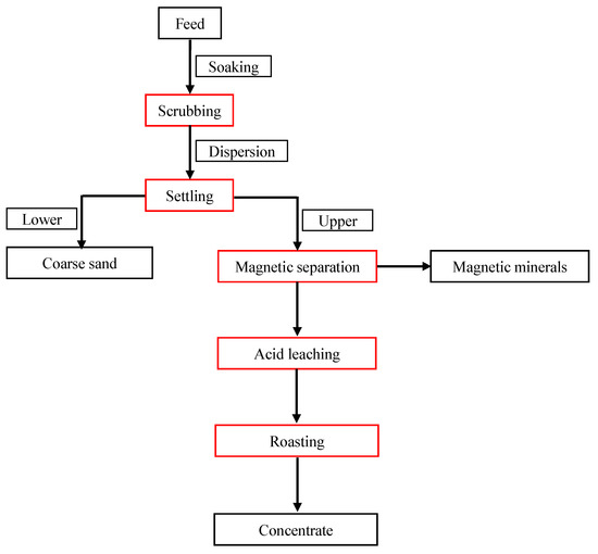
Figure 1.
Proposed flowsheet for the processing of low-grade diatomite.

Table 1.
Chemical analysis of the diatomite.
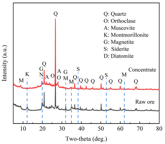
Figure 2.
XRD patterns of the diatomite before and after purification.
Table 1 and Figure 2 present the comparison between the raw diatomite and the concentrate. Regarding the chemical composition, Table 1 indicates that the concentrate has high silica (about 86.93%) and low iron (1.24%), but is still high in alumina (6.75%). The high alumina content is attributed to clay and feldspars particles which associate with diatoms during separation. Table 2 presents data for specific surface area, most countable pore diameter, average pore diameter, and pore volume. These data indicate that the specific surface area increased from 49.68 m2·g−1 in the feed to 77.30 m2·g−1 in the concentrate, most countable pore diameter increased from 3.81 nm to 10.14 nm, pore volume increased from 0.23 mL·g−1 to 0.33 mL·g−1, while average pore diameter reduced from 13.18 nm to 12.27 nm. Figure 2 shows the XRD diffraction patterns of the concentrate and raw diatomite. The data for the latter indicates the high reduction of quartz and clay in the concentrate and the increase of the broad peak of opal.
Table 2.
Parameters of the diatomite before and after purification.
2.2. XRD Analysis
Powder XRD was performed in order to investigate the crystal structure of the phases in the nanocomposite, and the results are shown in Figure 3 and Table 3. The typical diffraction peaks located at two-theta 25.31°, 36.95°, 37.79°, 38.57°, 48.05°, 53.88°, and 62.69° agree well with the primary reflections of the (101), (103), (004), (112), (200), (105), and (204) planes of the nano-TiO2 (PDF#71-1166), respectively. The diffraction peaks of pure g-C3N4 appearing at two-theta 12.86° and 27.59° are indexed as reflection from (100) and (002) planes corresponding to the inter-layer structural packing and the characteristic inter-planar stacking of the aromatic systems, respectively [34,35]. The diffraction peaks corresponding to TiO2 are clearly visible in the 5-CN-TO composite, but the diffraction peaks corresponding to g-C3N4 are not obvious, which is due to the sublimation of urea during the heating process, lessening the content of g-C3N4 in the composite. The diffraction peaks at two-theta 20.92° and 26.70° are indexed as reflection from (100) and (101) planes, corresponding to the characteristic peaks of SiO2 (PDF#85-0865) in the diatomite. The diffraction peak at two-theta 25.31° corresponds to the (101) plane of the anatase phase TiO2, and the diffraction peaks at 20.92° and 26.70° correspond to the characteristic peaks of SiO2. In contrast, the absence of significant g-C3N4 diffraction peaks in 0.1-NT-DE-550 °C-2.0 h is attributed to the low content of g-C3N4.
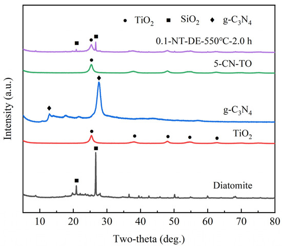
Figure 3.
XRD patterns of different photocatalytic materials.
Table 3.
Phase structure and crystal of different photocatalytic materials.
The diffraction peak at two-theta of 25.31° (101) was selected as a representative characteristic peak of the sample, and the average crystal size of TiO2 was calculated according to the Scherer equation. It can be seen that the average crystal size of the nano-TiO2 anatase phase is 7.0 nm; the average crystal size of the 5-CN-TO anatase phase is 8.3 nm; the average crystal size of the 0.1-NT-DE-550 °C-2.0 h anatase phase is also 8.3 nm. This indicates that the crystal size of the anatase phase becomes larger after the nano-TiO2 composite with g-C3N4 and diatomite. Among them, g-C3N4 promotes the growth of the TiO2 anatase phase and avoids more lattice defects, while the addition of diatomite almost does not affect the crystal structure of TiO2 [36].
2.3. XPS Analysis
The XPS was employed to confirm the chemical state of elements in the ternary TiO2/g-C3N4/diatomite nanocomposite. Figure 4a shows that the composite is mainly composed of C, N, O, Si, and Ti. The fine spectrum of C 1s (Figure 4b) indicates that C 1s can be deconvoluted into three peaks at 283.30 eV, 284.80 eV, and 287.21 eV; the first two are carbon impurities introduced during the sample processing, and the latter is attributed to sp2 hybridized C, such as (N)2-C=N [37,38]. The fine spectrum of N 1s (Figure 4c) suggests that the core state energy peak at 397.72 eV can be split into four peaks, 395.67 eV, 397.30 eV, 398.65 eV, and 400.20 eV, corresponding to nitrogen-doped Ti-N, sp2 hybridized nitrogen (C=N-C), urea polymerization resulting in N-(C)3, and the amino functional group NHx (x = 1, 2) [39,40,41,42,43,44]. The fine spectrum of O 1s (Figure 4d) shows that the three peaks at 528.36 eV, 531.24 eV, and 533.84 eV correspond to three different chemical states of O 1s, including O2− in the TiO2 lattice, OH− groups on the surface of the composite, and O2− with adsorbed H2O. The content of OH− groups on the surface of the composite is higher than that of TiO2, while the surface OH− group at 531.24 eV plays an important role in improving the photocatalytic efficiency by trapping holes (h+) and generating ·OH, thus inhibiting the complex between electrons (e−) and h+ [45]. The Si 2p fine spectrum (Figure 4e) indicates that the absorption peak has a binding energy of 101.90 eV, which corresponds to the Si-O of diatomite [46]. The fine spectrum of Ti 2p (Figure 4f) suggests that the binding energies 456.98 eV and 462.95 eV corresponding to Ti 2p3/2 and Ti 2p1/2 for the composite are shifted 2.12 eV and 1.85 eV toward lower energies compared to the binding energies 459.10 eV and 464.80 eV corresponding to Ti 2p3/2 and Ti 2p1/2 for TiO2, respectively [47,48]. This shows that the presence of Ti-N electron interactions as well as the possible formation of N→Ti coordination bonds are probably due to the addition of g-C3N4 [29,49].
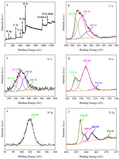
Figure 4.
XPS survey (a), C 1s (b), N 1s (c), O 1s (d), Si 2p (e), Ti 2p (f) of TiO2/g-C3N4/diatomite.
2.4. FT-IR Analysis
The FT-IR spectras for nano-TiO2, g-C3N4, 5-CN-TO, and 0.1-NT-DE-550 °C-2.0 h composites are shown in Figure 5. For nano-TiO2, the bands between 400 cm−1 and 700 cm−1 are attributed to the Ti-O-Ti and Ti-O stretching vibration [50]. The bands at 3349 cm−1 and 1634 cm−1 correspond to the -OH bending vibration of adsorbed water [51]. For pure g-C3N4, the band around 808 cm−1 is ascribed to out-of-plane bending modes of heterocyclic C-N (C-N=C and N=C-N). The peaks between 1228 cm−1 and 1630 cm−1 are attributed to C=N stretching vibration modes. In addition, the broad peak near 3200 cm−1 is attributed to the N-H and O-H stretching vibration [52]. For 5-CN-TO, the typical characteristic peaks of TiO2 and g-C3N4 can be observed, showing the vibration of Ti-O and C=N. This indicates that TiO2 and g-C3N4 are successfully compounded and can avoid more lattice defects. Furthermore, the intensity of the characteristic vibration peak of g-C3N4 is weakened, indicating that TiO2 and g-C3N4 are present in m-CN-TO at the same time, but there is less g-C3N4 content. For diatomite, the 1003 cm−1 asymmetric strong absorption band has a shoulder absorption at 1053.41 cm−1 attributed to Si-O antisymmetric stretching vibration. The band at 792 cm−1 is attributed to Si-O symmetric stretching vibration. Additionally, the band at 459 cm−1 is ascribed to O-Si-O antisymmetric bending vibration [53,54]. For 0.1-NT-DE-550 °C-2.0 h, the typical characteristic peaks of TiO2, g-C3N4, and diatomite can be observed, showing the vibration of Ti-O, C=N and Si-O. This suggests that the TiO2 nanoparticles, g-C3N4 flakes, and diatomite skeletons closely bind to each other [55].
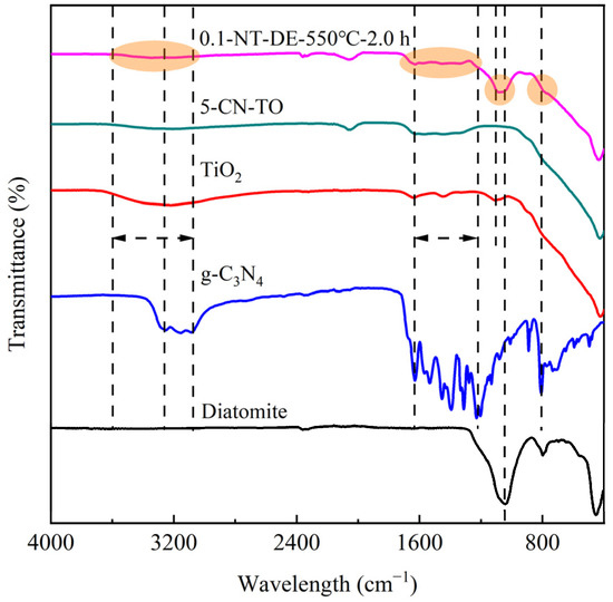
Figure 5.
FT-IR spectra of different photocatalytic materials.
2.5. N2 Adsorption-Desorption Analysis
The N2 adsorption-desorption measurements were performed to investigate the pore structure of the composites, including specific surface area, most available diameter, average pore diameter, and pore volume, as shown in Figure 6 and Table 4. The N2 adsorption-desorption isotherms of nano-TiO2, g-C3N4, diatomite, 5-CN-TO, and 0.1-NT-DE-550 °C-2.0 h are type IV and H3 hysteresis echoes, reflecting the pore structures such as flat slits, cracks, and wedges in the samples, where capillary coalescence occurred. The BET simulations reveal that the specific surface areas of TiO2, g-C3N4, diatomite, 5-CN-TO, and 0.1-NT-DE-550 °C-2.0 h are 301.26 m2·g−1, 87.47 m2·g−1, 148.63 m2·g−1, 179.77 m2·g−1, and 145.03 m2·g−1, respectively. This indicates that the presence of g-C3N4 and diatomite reduces the specific surface areas of the composites. The BJH simulations show that the pore volumes of TiO2, g-C3N4, diatomite, 5-CN-TO, and 0.1-NT-DE-550 °C-2.0 h are 0.39 mL·g−1, 1.63 mL·g−1, 0.34 mL·g−1, 0.43 mL·g−1, and 0.33 mL·g−1, respectively. This illustrates that the presence of g-C3N4 and diatomite reduces the pore volumes of the composites. The average pore diameters of TiO2, g-C3N4, diatomite, 5-CN-TO, and 0.1-NT-DE-550 °C-2.0 h are 4.73 nm, 43.55 nm, 7.96 nm, 7.78 nm, and 8.44 nm, respectively. This indicates that the presence of g-C3N4 and diatomite increases the average pore diameters of the composites. In addition, the most available diameters of TiO2, g-C3N4, diatomite, 5-CN-TO, and -550 °C-2.0 h are 1.95 nm, 22.84 nm, 3.50 nm, 3.53 nm, and 3.47 nm, respectively. This shows that the presence of g-C3N4 and diatomite increases the most available diameters of the composites. It can be seen that the synergy of the TiO2 nanoparticles, g-C3N4 flakes, and diatomite skeletons optimizes the functional structure of the composite.
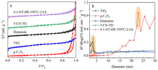
Figure 6.
N2 adsorption-desorption isotherms (a), pore size distribution curves (b) of different photocatalytic materials.
Table 4.
Specific surface area and pore structure parameters.
2.6. SEM Analysis
The SEM images of nano-TiO2, g-C3N4, diatomite, 5-CN-TO, and 0.1-NT-DE-550 °C-2.0 h are shown in Figure 7, revealing the morphology characteristics of different photocatalytic materials. The nano-TiO2 structure is spherical (Figure 7a) and the g-C3N4 structure is sheet-like (Figure 7b). At the same time, the agglomeration and accumulation between TiO2 nanoparticles and between g-C3N4 flakes are serious. The 5-CN-TO structure is mainly spherical (Figure 7a,b), and TiO2 nanoparticles are scattered and loaded on the g-C3N4 flake structure (Figure 7c). The presence of g-C3N4 inhibits the agglomeration of TiO2 nanoparticles and forms heterojunctions; the electrons on the g-C3N4 conduction band leap to the TiO2 conduction band through the heterojunctions; and the holes on the TiO2 valence band are transferred to the g-C3N4 valence band, improving the photocatalytic performance of TiO2 in the visible region [56,57,58,59]. Diatomite has a disc-shaped structure (Figure 7d) with a large number of nanoscale pores and a large specific surface area. With the addition of diatomite, the TiO2/g-C3N4 particles in the 0.1-NT-DE-550 °C-2.0 h are more uniformly distributed and smaller in size (Figure 7e). The surface of diatomite becomes rougher after compounding, providing more surface-active sites for the adsorption and degradation of the MB solution [55]. Figure 7f shows that the 1.0-NT-DE-550 °C-2.0 h has a very serious accumulation of TiO2, g-C3N4, and diatomite skeletons due to the large mass of diatomite, which reduces the photocatalytic active sites of the composite and is not conducive to the light absorption and degradation of the MB solution [60].
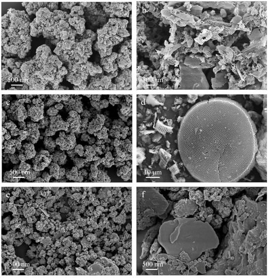
Figure 7.
SEM images of TiO2 (a), g-C3N4 (b), 5-CN-TO (c), diatomite (d), 0.1-NT-DE-550 °C-2.0 h (e), 1.0-NT-DE-550 °C-2.0 h (f).
2.7. TEM Analysis
The TEM, HRTEM, and SAED images of TiO2/g-C3N4/diatomite are shown in Figure 8. The g-C3N4 structure is sheet-like in the composite, TiO2 is mainly distributed on the surface of g-C3N4 flakes in the form of particles, and some agglomeration phenomenon occurs but is not obvious (Figure 8a,b).
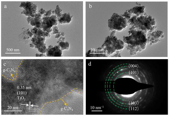
Figure 8.
TEM (a,b), HRTEM (c) and SADE (d) images of TiO2/g-C3N4/diatomite.
This is due to the fact that the presence of g-C3N4 and diatomite inhibits agglomeration and facilitates the absorption of visible light and the degradation of the MB solution. The TiO2 nanoparticles are in close contact with the g-C3N4 nanosheets, and the multi-level pore structure cannot be clearly observed in the TEM images due to the small mass of diatomite. Lattice fringes from TiO2 (101) are visible in the corresponding HRTEM image in Figure 8c with an inter-planar spacing of 0.35 nm, consistent with the card data (PDF#71-1166) and the calculation according to the corresponding ring pattern; moreover, the SADE pattern of the composite determines the lattice fringe of the anatase phase TiO2 (101) crystal plane to be 0.35 nm (Figure 8d) [61].
2.8. UV-Vis DRS Absorption Spectra Analysis
The UV-vis DRS spectras of TiO2, g-C3N4, 5-CN-TO, and 0.1-NT-DE-550 °C-2.0 h are shown in Figure 9a respectively. Correspondingly, the band gap was calculated following (αhv)1/2 = k(hv − Eg), where α, h, v, k, and Eg represent the absorption coefficient, Planck constant, light frequency, a constant, and band gap, respectively; the results can be seen in Figure 9b [62,63]. An adsorption edge in the ultraviolet range up to 400 nm appears for the nano-TiO2, which has a band gap of 3.20 eV. The maximum absorption wavelength of pure g-C3N4 is about 460 nm with a band gap of 2.78 eV, and it has strong absorption in the visible region. Compared with TiO2 and g-C3N4, the maximum absorption wavelength of the 5-CN-TO composite is significantly red-shifted, and the absorption intensity is significantly enhanced in the ultraviolet and visible range with a band gap of 1.84 eV.
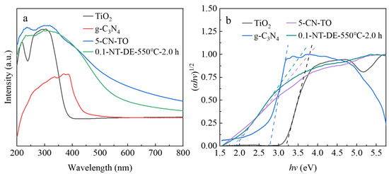
Figure 9.
UV-vis DRS spectras (a) and the band gap evaluation for linear dependence of (αhv)1/2 vs. hv (b) of different photocatalytic materials.
This is due to the superposition of the ultraviolet response of TiO2 and the visible response of g-C3N4 in the 5-CN-TO composite. The incorporation of g-C3N4 may indirectly cause a change in the electronic structure of TiO2 through the N→Ti coordination bond, narrowing the band gap to extend the visible response [64,65,66]. Furthermore, the band gaps of nano-TiO2 and g-C3N4 are 3.20 eV and 2.78 eV, respectively. Pure g-C3N4 can be excited by visible light and generate electrons, and the photogenerated electrons are transferred to the TiO2 conduction band through the interface of TiO2 and g-C3N4, which makes the visible light response range of the composite broaden. Compared with TiO2/g-C3N4, the absorption wavelength of 0.1-NT-DE-550 °C-2.0 h is blue-shifted, but the absorption intensity is slightly larger than that of TiO2/g-C3N4, around 400 nm. This indicates that the addition of diatomite reduces the absorption wavelength of TiO2/g-C3N4. On the other hand, the band gaps of TiO2/g-C3N4 and 0.1-NT-DE-550 °C-2.0 h are 1.84 eV and 1.91 eV, respectively, indicating that the electronic interaction between diatomite and TiO2/g-C3N4 leads to a change in the band gap of TiO2/g-C3N4. Moreover, the multi-level pore structure of the diatomite allows the active sites of 0.1-NT-DE-550 °C-2.0 h to increase and provides a strong adsorption capacity. The addition of diatomite facilitates the photocatalytic performance of the composites with similar band gaps [60].
2.9. Effect of Different Photocatalytic Materials
Figure 10a exhibits the influence of different photocatalytic materials on the degradation performance of the MB solution under visible light irradiation. After 360 min of reaction, the degradation rate of nano-TiO2 is only 16.10%, indicating that TiO2 has almost no visible light catalytic performance. g-C3N4 has a degradation rate of 29.41%, with a higher response to visible light than TiO2. 5-CN-TO shows a better visible light catalytic performance with a degradation rate of 87.35%, attributed to the effective improvement of the visible light response range of TiO2 by g-C3N4. Diatomite also has almost no visible light activity, but has 59.37% adsorption due to the adsorption of its multi-stage pore structure. 0.1-NT-DE-550 °C-2.0 h exhibits the best visible light catalytic performance, attributed to the synergistic effect of TiO2, g-C3N4, and diatomite, with 99.51% degradation of the MB solution. The monomeric characteristic absorption peak of MB is at 664 nm, and dimer characteristic absorption peak is at 615 nm [67]. Figure 10b indicates that the intensity of the characteristic absorption peaks of the MB solution decreases sequentially after the photocatalytic reaction of TiO2, g-C3N4, diatomite, 5-CN-TO, and 0.1-NT-DE-550 °C-2.0 h at 664 nm and 615 nm, respectively. Among them, the characteristic absorption peak of the MB solution almost disappears at 664 nm after 0.1-NT-DE-550 °C-2.0 h photocatalytic reaction, and only the dimer characteristic absorption peak with smaller intensity at 615 nm remains.
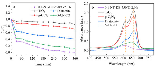
Figure 10.
Ct/C0 vs. time curve (a), absorption spectrum vs. wavelength curve (b) of different photocatalytic materials.
2.10. Cyclic Stability Analysis
The results of repeated MB conversion experiments with TiO2/g-C3N4/diatomite are shown in Figure 11. The results show that the best degradation effect is achieved in the 1st cyclic photocatalytic reaction with 98.77%; the degradation effect is similar in the 2nd and 3rd reactions, with 90.59% and 89.16%, respectively. The degradation effect tends to be stable after three cycles of photocatalytic reaction, and the composite still has a high degradation rate for the MB solution, indicating that the photocatalytic performance of the TiO2/g-C3N4/diatomite nanocomposite is stable, with good recyclability under visible light, and can be used for recycling in practical life and production. The enhanced photocatalytic activity and recyclability of TiO2/g-C3N4/diatomite compared to unary and binary photocatalytic materials. Among them, the degradation rate of TiO2/g-C3N4/diatomite prepared in this study is 1.66% higher for the MB solution in the 3rd photocatalytic reaction compared to the TiO2/g-C3N4 prepared by Hoa et al. [56], which is associated with the introduction of a diatomite skeleton, improving the mechanical and thermal stability and integrity to consequently maintain steady active sites for the conversion of the MB molecule.
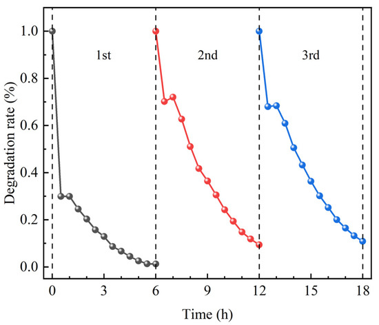
Figure 11.
Stability test results for the photodegradation of MB solution by TiO2/g-C3N4/diatomite.
2.11. Reactive Radical Capture Test
In order to further verify the effect of reactive radicals in the process of photocatalytic reaction, EDTA-2Na, BQ, and TBA are added to the MB solution as h+, O2−·, and ·OH trapping agents, and the results are shown in Table 5 and Figure 12, respectively. Figure 12a shows that the MB solution is gradually degraded and discolored as the photocatalytic reaction time increases. Among them, the inhibitory effect of BQ is the most obvious, with 89.56% degradation of the MB solution by the composite, followed by EDTA-2Na and TBA, with 94.99% and 96.82% degradation rates, respectively (Figure 12b). However, the degradation rate without trapping agents is 99.51%, indicating that O2−·, h+, and ·OH all play a role in the photocatalytic reaction process (Figure 12c). The order of degradation of the MB solution is blank > TBA > EDTA-2Na > BQ, indicating that the oxidation reaction occurring in the conduction band is the main cause of photocatalytic degradation of the MB solution. Meanwhile, diatomite loads TiO2 and g-C3N4 can better promote the separation of holes and electrons, and moreover, can provide more surface-active sites, thus improving the photocatalytic performance of the composite. Table 4 and Figure 12d show that the reaction rate constant kmax = 12.84 × 10⁻³ and R2 = 0.94 for the first-level kinetic equation of the catalytic reaction when no capture agent is added. In addition, the reaction rate constants k of the first-level kinetic equations for the capture agents are 7.34 × 10⁻³, 3.78 × 10⁻³, and 8.07 × 10⁻³ for EDTA-2Na, BQ, and TBA, respectively. The reaction rate constant of BQ is 1.75, 3.41, and 1.59 times higher than those of other capture agents, indicating that the O2−· mainly controls the photocatalytic reaction process of the MB solution.
Table 5.
Fitting parameters of photocatalytic reaction kinetics.
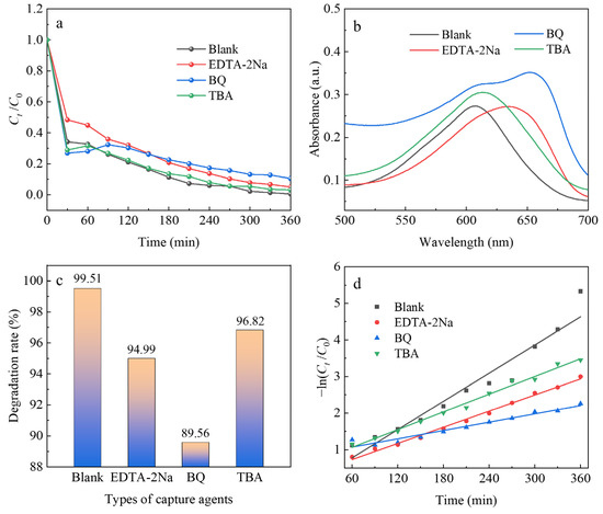
Figure 12.
Ct/C0 vs. time curve (a), absorption spectrum vs. wavelength curve (b), degradation rate histogram (c), −ln(Ct/C0) vs. time curve (d) of different capture agents.
2.12. Photocatalytic Degradation Mechanism
The TiO2/g-C3N4/diatomite composite exhibits excellent photocatalytic performance for the MB solution, and after characterization of the material structure and properties, it is found that the main reason for the improved photocatalytic performance of the composite is the significant extension of their spectral response range and the substantial increase in the number of reactive sites. Compared with the unary photocatalytic material, the photogenerated charge separation efficiency of the photocatalytic composite with diatomite loaded with TiO2 and g-C3N4 is significantly improved.
The photocatalytic degradation mechanism is proposed and elucidated in light of the above experimental results. The band edges of the valence band (VB) and conduction band (CB) of a semiconductor can be obtained using the following Equations (1) and (2) [47]:
where χ is the absolute electronegativity of the semiconductor (χ is 5.81 eV and 4.73 eV for TiO2 and g-C3N4, respectively [68]), Ee is the energy of the free electrons on the hydrogen scale (4.50 eV), and Eg is the band gap of the semiconductor. Based on the empirical energy band equation and the forbidden band width derived from Uv-vis DRS Tauc curves, the calculated CB and VB of g-C3N4 are −1.16 eV and 1.62 eV, respectively, which are more positive than those of TiO2 (−0.29 eV and 2.91 eV, respectively). The g-C3N4 can be activated when the nanocomposite is irradiated under visible light leaving an equivalent number of holes with positive charge in the corresponding positions, and the electrons in full VB of g-C3N4 may move to the empty CB [69]. Due to its narrower band gap (2.78 eV) as compared to TiO2 (3.20 eV), the presence of g-C3N4 facilitates the utilization of visible light. Moreover, well matched band structures between g-C3N4 and TiO2 favor the ready transferring of photogenerated electrons at the surface of g-C3N4 flakes to the surface of TiO2 particles to effectively prevent the recombination of photogenerated electrons and holes [70]. This migration effect of photogenerated carriers can effectively suppress the compounding of photogenerated electrons and holes, and improve the separation efficiency of carriers. More photogenerated electrons in the conduction band of TiO2 and more holes in the valence band of g-C3N4 greatly increase the active sites on the surface of the composite, accelerating the production of O2−· and ·OH in the system. The reaction of photogenerated electrons on the TiO2 CB with dissolved O2 forms O2−·, while some of the O2−· reacts with H2O/H+ to produce a small amount of ·OH. The VB potential of g-C3N4 (1.62 eV) is higher than that of H2O/OH (1.99 eV), so the photogenerated holes react directly with MB without producing ·OH. In addition, diatomite contains a large number of hydroxyl groups and hydrogen bonds on its surface, which can produce more Bronsted acidic sites. The acidic sites can effectively trap the positively charged photogenerated holes, providing more active adsorption sites and photocatalytic reaction centers. Si-OH can react with photogenerated holes to form ·OH., and diatomite with a large number of microporosity can adsorb MB molecules, making TiO2/g-C3N4 better for photocatalytic reaction with the MB solution. Eventually, under the synergistic effect of TiO2, g-C3N4, and diatomite in the composite, O2−·, h+, ·OH, and MB molecules undergo oxidation reaction so that the strong chromophore within the MB molecule is attacked and the large conjugated system is destroyed and degraded to inorganic small molecules, H2O and CO2. It can be seen that the composite of TiO2, g-C3N4 and diatomite increases the possibility of photocatalytic reaction of visible light on the surface of TiO2, and increases the quantum efficiency of g-C3N4 and the number of active sites on the surface of the composite [60]. The reaction pathway is speculated as follows (Equations (3)–(9)):
Figure 13 is a schematic diagram of the electron-hole migration and separation pathways on the surface of the TiO2/g-C3N4/diatomite composite.
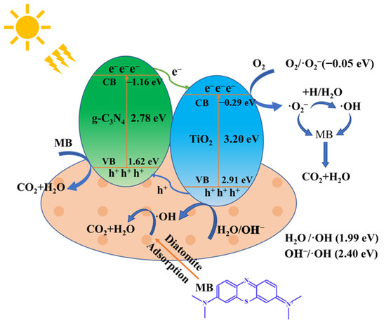
Figure 13.
Schematic diagram of electron-hole migration and separation pathways on the surface of TiO2/g-C3N4/diatomite.
3. Materials and Methods
3.1. Materials
The raw diatomite was obtained from the diatomite planning area in Heilongjiang, China. Sulfuric acid (H2SO4) was provided by Liaoning Quanrui Reagent Co., Ltd., Jinzhou, China. Sodium hydroxide (NaOH), sodium hexametaphosphate ((NaPO3)6), urea (CH4N2O), and MB were provided by Sinopham Chemical Regent Co., Ltd., Beijing, China. Nano-TiO2, disodium ethylenediaminetetraacetate (EDTA-2Na), benzoquinone (BQ), and tert-butanol (TBA) were provided by Shanghai Aladdin Biochemical Technology Co., Ltd., Shanghai, China. The diatomite needed to be further purified; other reagents were analytical grade and used without further purification.
3.2. Purification of Low-Grade Diatomite
200 g of low-grade diatomite was dispersed in 300 mL of water and soaked for 2 h. The soaked diatomite was scrubbed in a scrubbing machine at a rotational speed of 1300 r·min−1, a material concentration of 25%, a time of 30 min, a dosage of 0.3% NaOH, a dosage of 0.3% (NaPO3)6, a settling time of 0.5 min, and a siphoning depth of 13 cm. The upper pulp was treated with magnetic separation in a 1.91 T wet strong magnetic separator. The non-magnetic pulp was dewatered and put into a three-necked bottle placed in an oil bath for leaching treatment at a H2SO4 concentration of 26.63%, a temperature of 130 °C, a solid-liquid ratio of 1:4, a rotational speed of 150 r·min−1, and a time of 6 h. The leached material was dehydrated and roasted in a chamber resistance furnace at a heating rate of 10 K·min−1, a temperature of 600 °C, and a time of 2.0 h to obtain the diatomite concentrate.
3.3. Synthesis of TiO2/g-C3N4 and TiO2/g-C3N4/Diatomite
The nano-TiO2 and urea were ultrasonically dispersed in the 50 mL of deionized water at a mass ratio of 1:5 to obtain TiO2/g-C3N4 precursor. The nano-TiO2/urea and diatomite concentrate were ultrasonically dispersed at a mass ratio of 1:0.1 to obtain TiO2/g-C3N4/diatomite precursor. The dispersed materials were dried in an electric thermostatic blast dryer at 60 °C and then fully ground in an agate bowl. The milled materials were loaded into an alumina crucible and placed in a chamber resistance furnace and heated up to 550 °C at a heating rate of 5 K·min−1 and held for 2.0 h to obtain the TiO2/g-C3N4 composite and the TiO2/g-C3N4/diatomite composite, numbered 5-CN-TO and 0.1-NT-DE-550 °C-2.0 h, respectively. Meanwhile, g-C3N4 was made from urea by the above thermal polymerization process.
3.4. Characterization
The structure of the samples was measured by X-ray diffraction (XRD) with a D8 Adcance diffractometer (Bruker, Karlsruhe, Germany) using Cu Kα radiation at diffraction wavelength of 0.15406 nm, operating voltage of 40 kV, tube current of 40 mA, scan speed of 12°·min−1, and scan range of 5° to 80°. The sample was prepared by selecting a copper mesh, and ultrasonically dispersed with ethanol for 5 min. The group structures were analyzed by Fourier transform infrared spectrometer (FT-IR) using a Tensor II (Bruker, Karlsruhe, Germany) equipped with an ATR accessory at wave number range of 4000~400 cm−1, resolution of 4 cm−1, and scan number of 16. The N2 adsorption-desorption measurement was performed using 3H-2000PMV (Beishide Instrument, Beijing, China) at a heating temperature of 473.15 K and degassing time of 6 h. The UV-vis diffuse reflectance spectra (DRS) of the catalysts were collected on a UV-vis spectrometer (Hitachi U4150, Hitachi, Tokyo, Japan) equipped with an integrating sphere at a test range of 200~800 nm, and the reference substance was BaSO4 white plate. The absorbance of the centrifuged MB supernatant at 664 nm and the absorption scan spectrum at a scan range of 400~780 nm, step size of 0.5 nm, and accuracy of 30 were measured using an ultraviolet visible spectrophotometer (UV-6000PC, Shanghai Metash Instruments, Shanghai, China). A scanning electron microscope (SEM) was used to characterize the morphology of the samples.
3.5. Photocatalytic Degradation of MB Mechanism
A 350 W xenon lamp (HDL-II, Anhui Aoke Test Equipment Co., Ltd., Anhui, China) was used to simulate the light source, a 10 mg·L−1 MB solution was used as the contaminant, and 0.4 mg·L−1 TiO2/g-C3N4/diatomite composite was added to the MB solution. The reaction system was placed in a dark place before turning on the light source, and the adsorption was avoided for 60 min to make the composites reach the adsorption-desorption equilibrium. The reaction was carried out for 360 min, and the absorbance of the supernatant was measured at 664 nm after sampling at 30 min intervals and centrifugation at 3000 r·min−1 to obtain Ct/C0.
The composite after the photocatalytic reaction was separated from the MB solution by centrifugation; rinsed with deionized water and ethanol in turn for three times, respectively, to reduce the influence of other impurities; dried and collected in an electric thermostatic blast drying oven; and tested again according to the test procedure of photocatalytic performance to evaluate the stability of the photocatalytic reaction of the composite.
The role of reactive radicals during the TiO2/g-C3N4/diatomite photocatalytic reaction was determined by the capture test. EDTA-2Na, BQ, and TBA were added to the MB solution as capture agents for h+, O2−·, ·OH, respectively.
The photocatalytic reaction primary kinetic model is shown in Equation (10) [34].
where C0 is the initial MB concentration of the solution at each measurement; Ct is the MB concentration at the moment t of the reaction; k is the reaction rate constant; t is the reaction time; m is the mass of the composites.
4. Conclusions
The combined scrubbing-magnetic separation-acid leaching-roasting process was used to increase the SiO2 content from 59.22% to 86.93%, reduce the Al2O3 content from 18.32% to 6.75%, and reduce the Fe2O3 content from 6.85% to 1.24% of the low-grade diatomite from Heilongjiang, China, under optimal process conditions. Meanwhile, an ultrasonic-thermal polymerization method applicable to the preparation of fabricating ternary TiO2/g-C3N4/diatomite nanocomposite from the low-grade diatomite purified concentrate was proposed, and the degradation rate of the MB solution reached 99.51%. The interaction effects of carrier ratio, polymerization temperature, and polymerization time on the photocatalytic performance of the TiO2/g-C3N4/diatomite composite was obvious; the effects of all three factors on the degradation of the MB solution reached a highly significant level, and the magnitude of the influence ability was: carrier ratio > polymerization temperature > polymerization time. O2−·, h+, ·OH all played a role in the photocatalytic reaction of the TiO2/g-C3N4/diatomite to the MB solution, where O2−· mainly controlled the photocatalytic process. The TiO2/g-C3N4/diatomite composite had the best degradation effect on the MB solution in the 1st cycle with 98.77%; the 2nd and 3rd cycles had similar degradation effects with 90.59% and 89.16%, respectively, and the degradation effects tended to be stable. After 3 cycle reactions, the composite still had a high degradation rate to the MB solution and could be used for recycling in practice. This nanostructured TiO2/g-C3N4/diatomite composite has fascinating visible light catalytic activity and excellent stability, which opens a new path for the comprehensive development and utilization of low-grade diatomite resources.
Author Contributions
Conceptualization, J.Z. and L.C.; methodology, L.C.; software, L.C.; validation, J.Z., X.W. and J.G.; formal analysis, L.C.; investigation, Z.M.; resources, Z.M.; data curation, L.C.; writing—original draft preparation, L.C.; writing—review and editing, L.C.; visualization, J.G.; supervision, X.W.; project administration, Z.M.; funding acquisition, Z.M. All authors have read and agreed to the published version of the manuscript.
Funding
This research was partially funded by the National Science Foundation of China, grant number 51372108.
Data Availability Statement
Not applicable.
Acknowledgments
The authors thank H. Guo for help with this research.
Conflicts of Interest
The authors declare no conflict of interest.
References
- Li, C.; Li, G.; Chen, D.; Gao, K.; Cao, Y.; Zhou, Y.; Mao, Y.; Fan, S.; Tang, L.; Jia, H. The effects of diatomite as an additive on the macroscopic properties and microstructure of concrete. Materials 2023, 16, 1833. [Google Scholar] [CrossRef] [PubMed]
- Łach, M.; Pławecka, K.; Marczyk, J.; Ziejewska, C.; Hebdowska-Krupa, M.; Nykiel, M.; Hebda, M.; Miernik, K.; Mierzwiński, D.; Korniejenko, K.; et al. Use of diatomite from polish fields in sustainable development as a sorbent for petroleum substances. J. Clean. Prod. 2023, 389, 136100. [Google Scholar] [CrossRef]
- Hao, L.; Gao, W.; Yan, S.; Niu, M.; Liu, G.; Hao, H. Preparation and characterization of porous ceramics with low-grade diatomite and oyster shell. Mater. Chem. Phys. 2019, 235, 121741. [Google Scholar] [CrossRef]
- Li, Q.; Guo, W.; Kong, X.; Xu, J.; Xu, C.; Chen, Y.; Chen, J.; Jia, X.; Ding, Y. MnFe2O4/rGO/diatomite composites with excellent wideband electromagnetic microwave absorption. J. Alloy. Compd. 2023, 941, 168851. [Google Scholar] [CrossRef]
- Fan, Z.; Li, Z.; Qi, W.; Zhao, S.; Zhou, B.; Liu, S.; Tian, Y. Preparation of in-situ modified diatomite and its application in papermaking. Colloid. Surf. A 2023, 657, 130582. [Google Scholar] [CrossRef]
- Alfassam, H.E.; Ashraf, M.T.; Othman, S.A.; Waili, M.A.; Allam, A.A.; Abukhadra, M.R. Synthesis and characterization of cellulose functionalized zeolitic diatomite as an enhanced carrier of oxaliplatin drug; loading, release, and cytotoxicity. Int. J. Biol. Macromol. 2023, 235, 123825. [Google Scholar] [CrossRef]
- Wang, J.; Zhang, G.; Qiao, S.; Zhou, J. Comparative assessment of formation pathways and adsorption behavior reveals the role of NaOH of MgO-modified diatomite on phosphate recovery. Sci. Total. Environ. 2023, 876, 162785. [Google Scholar] [CrossRef]
- Zhao, Y.; Sun, Q.; Zhang, J.; Sheng, J. Construction of Fe/N/C nano-clusters anchored on porous diatomite for efficient removal of norfloxacin via the adsorption-PMS activation. Sep. Purif. Technol. 2023, 310, 123127. [Google Scholar] [CrossRef]
- Li, M.; Liu, D.; Wang, S.; Guo, H.; Losic, D.; Deng, L.; Wu, S.; Yuan, P. Efficient removal of Cd2+ by diatom frustules self-modified in situ with intercellular organic components. Environ. Pollut. 2023, 319, 121005. [Google Scholar] [CrossRef]
- Gao, L.; Luo, Y.; Kang, Y.; Gao, M.; Abdulhafidh, O. Experimental study on physical mechanical properties and microstructure of diatomite soil in Zhejiang province, China. Appl. Sci. 2022, 12, 387. [Google Scholar] [CrossRef]
- Su, C.; Jiang, C.; Sun, X.; Cao, Z.; Mu, Y.; Cong, X.; Qiu, K.; Lin, J.; Chen, X.; Feng, C. Diatomite hemostatic particles with hierarchical porous structure for rapid and effective hemostasis. Colloid. Surface. B 2022, 219, 112809. [Google Scholar] [CrossRef] [PubMed]
- Chen, F.; Miao, Y.; Ma, L.; Zhan, F.; Wang, W.; Chen, N.; Xie, Q. Optimization of pore structure of a clayey diatomite. Particul. Sci. Technol. 2022, 38, 522–528. [Google Scholar] [CrossRef]
- Ding, R.; Jin, X.; Liu, G. Characteristics of diatomite mineral resources and analysis of supply and demand situation in China. Jilin Geol. 2021, 40, 25–29+42. (In Chinese) [Google Scholar]
- Ministry of Natural Resources of the People’s Republic of China. National Mineral Resources Reserves Statistics in 2020. Ministry of Natural Resources. 2021; p. 15. Available online: https://www.mnr.gov.cn/sj/sjfw/kc_19263/kczycltjb/202111/t20211122_2706327.html (accessed on 16 February 2023).
- Ministry of Natural Resources of the People’s Republic of China. National Mineral Resources Reserves Statistics in 2021. Ministry of Natural Resources. 2022; p. 17. Available online: https://www.mnr.gov.cn/sj/sjfw/kc_19263/kczycltjb/202208/t20220826_2757756.html (accessed on 16 February 2023).
- U.S. Geological Survey. Mineral Commodity Summaries 2023: U.S. Geological Survey. 2023; p. 210. [Google Scholar] [CrossRef]
- U.S. Geological Survey. Mineral Commodity Summaries 2022: U.S. Geological Survey. 2022; p. 202. [Google Scholar] [CrossRef]
- Ewuzie, U.; Saliu, O.D.; Dulta, K.; Ogunniyi, S.; Bajeh, A.O.; Iwuozor, K.O.; Ighalo, J.O. A review on treatment technologies for printing and dyeing wastewater (PDW). J. Water. Process. Eng. 2022, 50, 103273. [Google Scholar] [CrossRef]
- Ito, T.; Adachi, Y.; Yamanashi, Y.; Shimada, Y. Long–term natural remediation process in textile dye-polluted river sediment driven by bacterial community changes. Water Res. 2016, 100, 458–465. [Google Scholar] [CrossRef]
- Rehman, M.S.U.; Kim, I.; Han, J.I. Adsorption of methylene blue dye from aqueous solution by sugar extracted spent rice biomass. Carbohyd. Polym. 2012, 90, 1314–1322. [Google Scholar] [CrossRef]
- Maia, L.S.; da Silva, A.I.C.; Carneiro, E.S.; Monticelli, F.M.; Pinhati, F.R.; Mulinari, D.R. Activated carbon from palm fibres used as an adsorbent for methylene blue removal. J. Polym. Environ. 2021, 29, 1162–1175. [Google Scholar] [CrossRef]
- Han, X.; Wang, W.; Ma, X. Adsorption characteristics of methylene blue onto low cost biomass material lotus leaf. Chem. Eng. J. 2011, 171, 1–8. [Google Scholar] [CrossRef]
- Sheikh, F.A.; Ntiamoah, R.A.; Zargar, M.A.; Chandradass, J.; Chung, W.J.; Kim, H. Photocatalytic properties of Fe2O3-modified rutile TiO2 nanofibers formed by electrospinning technique. Mater. Chem. Phys. 2016, 172, 62–68. [Google Scholar] [CrossRef]
- Solayman, H.M.; Hossen, M.A.; Aziz, A.A.; Yahya, N.Y.; Leong, K.H.; Sim, L.C.; Monir, M.U.; Zoh, K.D. Performance evaluation of dye wastewater treatment technologies: A review. J. Environ. Chem. Eng. 2023, 11, 109610. [Google Scholar] [CrossRef]
- Wudil, Y.S.; Ahmad, U.F.; Gondal, M.A.; Osta, M.A.A.; Almohammedi, A.; Sa’id, R.S.; Hrahsheh, F.; Haruna, K.; Mohamed, M.J.S. Tuning of graphitic carbon nitride (g-C3N4) for photocatalysis: A critical review. Arab. J. Chem. 2023, 16, 104542. [Google Scholar] [CrossRef]
- Zhao, X.; Liu, Q.; Li, X.; Ji, H.; Shen, Z. Two-dimensional g-C3N4 nanosheets-based photo-catalysts for typical sustainable processes. Chin. Chem. Lett. 2023, 108306, in press. [Google Scholar] [CrossRef]
- Liyanaarachchi, H.; Thambiliyagodage, C.; Liyanaarachchi, C.; Samarakoon, U. Efficient photocatalysis of Cu doped TiO2/g-C3N4 for the photodegradation of methylene blue. Arab. J. Chem. 2023, 16, 104749. [Google Scholar] [CrossRef]
- Li, C.; Sun, L.; Niu, J.; Reka, A.A.; Feng, P.; Garcia, H. Core-shell Bi-containing spheres and TiO2 nanoparticles co-loaded on kaolinite as an efficient photocatalyst for methyl orange degradation. Catal. Commun. 2023, 175, 106609. [Google Scholar] [CrossRef]
- Fu, B.; Guo, S.; Fu, M.; Li, Z. Preparation and photocatalytic property of graphitic carbon nitride (g-C3N4) hybridized TiO2 nanometer materials. J. Funct. Mater. 2014, 45, 12138–12144. (In Chinese) [Google Scholar]
- Mohamed, W.A.A.; El-Gawad, H.H.A.; Handal, H.T.; Galal, H.R.; Mousa, H.A.; ElSayed, B.A.; Labib, A.A.; Abdel-Mottaleb, M.S.A. Study of phytotoxicity, remarkable photocatalytic activity, recycling process and energy consumption cost of TiO2 quantum dots photocatalyst for photodegradation of Coomassie brilliant blue R dye. Opt. Mater. 2023, 137, 113607. [Google Scholar] [CrossRef]
- Zhang, Y.; Chen, X.; Cui, M.S.; Guo, Z.; Chen, Y.H.; Cui, K.P.; Ding, Z.G.; Weerasooriya, R. Binding Fe-doped g-C3N4 on the porous diatomite for efficient degradation of tetracycline via photo-Fenton process. J. Environ. Chem. Eng. 2022, 10, 107406. [Google Scholar] [CrossRef]
- Dai, N.; Yi, S.; Zhang, X.; Feng, L.; Ding, H.; Song, D.; Liu, X.; Rao, J.; Zhang, Y. Typical synthesis of an iron-modified Laponite @diatomite composite for photo-Fenton degradation of methyl orange dyes. Appl. Surf. Sci. 2023, 607, 154886. [Google Scholar] [CrossRef]
- Zhu, P.; Chen, Y.; Duan, M.; Liu, M.; Zou, P. Structure and properties of Ag3PO4/diatomite photocatalysts for the degradation of organic dyes under visible light irradiation. Powder Technol. 2018, 336, 230–239. [Google Scholar] [CrossRef]
- Jouybari, M.H.; Hosseini, S.; Mahboobnia, K.; Boloursaz, L.A.; Moradi, M.; Irani, M. Simultaneous controlled release of 5-FU, DOX and PTX from chitosan/PLA/5-FU/g-C3N4-DOX/g-C3N4-PTX triaxial nanofibers for breast cancer treatment in vitro. Colloid. Surf. B 2019, 179, 495–504. [Google Scholar] [CrossRef]
- Vijayanath, S.; Janaki, K. Tailoring power conversion efficiency of dye sensitized solar cell based on ZnO/g-C3N4 hybrid photoelectrodes via microwave irradiation route. Inorg. Chem. Commun. 2020, 120, 108119. [Google Scholar] [CrossRef]
- Li, Y.; Sun, B.; Wang, A.; Gao, H. Preparation of TiO2-g-C3N4 composites and its application in cement stone surface. Acta Mater. Compos. Sin. 2020, 37, 1981–1988. (In Chinese) [Google Scholar]
- Thomas, A.; Fischer, A.; Goettmann, F.; Antonietti, M.; Müller, J.O.; Schlöglb, R.; Carlssonc, J.M. Graphitic carbon nitride materials: Variation of structure and morphology and their use as metal-free catalysts. J. Mater. Chem. 2008, 18, 4893–4908. [Google Scholar] [CrossRef]
- Guo, Q.; Xie, Y.; Wang, X.; Lv, S.; Hou, T.; Liu, X. Characterization of well-crystallized graphitic carbon nitride nanocrystallites via a benzene-thermal route at low temperatures. Chem. Phys. Lett. 2003, 380, 84–87. [Google Scholar] [CrossRef]
- Momma, K.; Izumi, F. VESTA 3 for three-dimensional visualization of crystal, volumetric and morphology data. J. Appl. Crystallogr. 2011, 44, 1272–1276. [Google Scholar] [CrossRef]
- Xu, X.; Wang, S.; Yu, X.; Dawa, J.; Gui, G.; Tanget, R. Biosynthesis of Ag deposited phosphorus and sulfur co-doped g-C3N4 with enhanced photocatalytic inactivation performance under visible light. Appl. Surf. Sci. 2020, 501, 144245. [Google Scholar] [CrossRef]
- Zhang, Y.; Thomas, A.; Antonietti, M.; Wang, X. Activation of carbon nitride solids by protonation: Morphology changes, enhanced ionic conductivity, and photoconduction experiments. J. Am. Chem. Soc. 2009, 131, 50–51. [Google Scholar] [CrossRef]
- Sun, Y.; Li, C.; Xu, Y.; Bai, H.; Yao, Z.; Shi, G. Chemically converted graphene as substrate for immobilizing and enhancing the activity of a polymeric catalyst. Chem. Commun. 2010, 46, 4740–4742. [Google Scholar] [CrossRef] [PubMed]
- Liu, J.; Zhang, T.; Wang, Z.; Dawsona, G.; Chen, W. Simple pyrolysis of urea into graphitic carbon nitride with recyclable adsorption and photocatalytic activity. J. Mater. Chem. 2011, 21, 14398–14401. [Google Scholar] [CrossRef]
- Dong, F.; Wu, L.; Sun, Y.; Fu, M.; Wu, Z.; Lee, S.C. Efficient synthesis of polymeric g-C3N4 layered materials as novel efficient visible light driven photocatalysts. J. Mater. Chem. 2011, 21, 15171–15174. [Google Scholar] [CrossRef]
- Huang, Y.; Ho, W.; Lee, S.; Zhang, L.; Li, G.; Yu, J.C. Effect of carbon doping on the mesoporous structure of nanocrystalline titanium dioxide and its solar-light-driven photocatalytic degradation of NOx. Langmuir 2008, 24, 3510–3516. [Google Scholar] [CrossRef]
- Jia, Z.H.; Li, T.; Zheng, Z.F.; Zhang, J.D.; Liu, J.X.; Li, R.; Wang, Y.W.; Zhang, X.C.; Wang, Y.F.; Fan, C.M. The BiOCl/diatomite composites for rapid photocatalytic degradation of ciprofloxacin: Efficiency, toxicity evaluation, mechanisms and pathways. Chem. Eng. J. 2020, 380, 122422. [Google Scholar] [CrossRef]
- Li, X.; Zhu, W.; Lu, X.; Zuo, S.; Yao, C.; Ni, C. Integrated nanostructures of CeO2/attapulgite/g-C3N4 as efficient catalyst for photocatalytic desulfurization: Mechanism, kinetics and influencing factors. Chem. Eng. J. 2017, 326, 87–98. [Google Scholar] [CrossRef]
- Wang, B.; Zhang, G.; Zheng, S.; Wang, J.; Li, C. Photocatalytic performance of cerium doped nano titanium oxide/diatomite composites. J. Chin. Ceram. Soc. 2016, 44, 1192–1199. [Google Scholar]
- Sathish, M.; Viswanathan, B.; Viswanath, R.P.; Gopinath, C.S. Synthesis, characterization, electronic structure, and photocatalytic activity of nitrogen-doped TiO2 nanocatalyst. Chem. Mater. 2005, 17, 6349–6353. [Google Scholar] [CrossRef]
- Tan, R.; He, Y.; Zhu, Y.; Xu, B.; Cao, L. Hydrothermal preparation of mesoporous TiO2 powder from Ti(SO4)2 with poly (ethylene glycol) as template. J. Mater. Sci. 2003, 38, 3973–3978. [Google Scholar] [CrossRef]
- Padmanabhan, S.K.; Pal, S.; Haq, E.U.; Licciulli, A. Nanocrystalline TiO2-diatomite composite catalysts: Effect of crystallization on the photocatalytic degradation of rhodamine B. Appl. Catal. A-Gen. 2014, 485, 157–162. [Google Scholar] [CrossRef]
- Huang, Z.; Sun, Q.; Lv, K.; Zhang, Z.; Li, M.; Li, B. Effect of contact interface between TiO2 and g-C3N4 on the photoreactivity of g-C3N4/TiO2 photocatalyst: (001) vs. (101) facets of TiO2. Appl. Catal. B-Environ. 2015, 164, 420–427. [Google Scholar] [CrossRef]
- Bairagi, N.; Gulrajani, M.L.; Deopura, B.L.; Shrivastava, A. Dyeing of N-modified viscose rayon fibres with reactive dyes. Color. Technol. 2005, 121, 113–120. [Google Scholar] [CrossRef]
- Emam, H.E.; Mowafi, S.; Mashaly, H.M.; Rehan, M. Production of antibacterial colored viscose fibers using in situ prepared spherical Ag nanoparticles. Carbohyd. Polym. 2014, 110, 148–155. [Google Scholar] [CrossRef]
- Tang, W.; Qiu, K.; Zhang, P.; Yuan, X. Synthesis and photocatalytic activity of ytterbium-doped titania/diatomite composite photocatalysts. Appl. Surf. Sci. 2016, 362, 545–550. [Google Scholar] [CrossRef]
- Hoa, D.T.N.; Tu, N.T.T.; Thinh, H.Q.A.; Son, L.V.T.; Son, L.V.T.; Quyen, N.D.V.; Son, L.L.; Tuyen, T.N.; Thong, P.L.M.; Diem, L.H.; et al. TiO2/g-C3N4 visible-light-driven photocatalyst for methylene blue decomposition. J. Nanomater. 2023, 2023, 9967890. [Google Scholar] [CrossRef]
- Wei, H.; McMaster, W.A.; Tan, J.Z.Y.; Cao, L.; Chen, D.; Caruso, R.A. Mesoporous TiO2/g-C3N4 microspheres with enhanced visible-light photocatalytic activity. J. Phys. Chem. C. 2017, 121, 22114–22122. [Google Scholar] [CrossRef]
- Reli, K.K.M.; Troppová, I.; Šihor, M.; Kupková, J.; Kustrowski, P.; Praus, P. Photocatalytic decomposition of N2O over TiO2/g-C3N4 photocatalysts heterojunction. Appl. Surf. Sci. 2017, 396, 1685–1695. [Google Scholar]
- Lei, J.; Chen, B.; Lv, W.; Zhou, L.; Wang, L.; Liu, T.; Zhang, J. An inverse opal TiO2/g-C3N4 composite with a heterojunction for enhanced visible light-driven photocatalytic activity. Dalton. T. 2019, 48, 3486–3495. [Google Scholar] [CrossRef]
- Liu, R.; Wang, J.; Zhang, J.; Xie, S.; Wang, X.; Ji, Z. Honeycomb-like micro-mesoporous structure TiO2/sepiolite composite for combined chemisorption and photocatalytic elimination of formaldehyde. Micropor. Mesopor. Mat. 2017, 248, 234–245. [Google Scholar] [CrossRef]
- Ramos, M.A.A.; Torres, M.O.F.; Chi, F.O.; González, C.G.E.; Como, N.H.; Zaleta, D.S.G.; Kesarla, M.K.; Torres, J.G.T.; Martínez, V.C.; Godavarthi, S. Fabrication of g-C3N4/TiO2 heterojunction composite for enhanced photocatalytic hydrogen production. Ceram. Int. 2020, 46, 38–45. [Google Scholar] [CrossRef]
- Gao, X.; Liu, X.; Zhu, Z.; Wang, X.; Xie, Z. Enhanced photoelectrochemical and photocatalytic behaviors of MFe2O4 (M = Ni, Co, Zn and Sr) modified TiO2 nanorod arrays. Sci. Rep. 2016, 6, 30543. [Google Scholar] [CrossRef]
- Yang, Y.C.; Liu, Y.; Wei, J.H.; Pan, C.X.; Xiong, R.; Shi, J. Electrospun nanofibers of p-type BiFeO3/n-type TiO2 hetero-junctions with enhanced visible-light photocatalytic activity. RSC Adv. 2014, 4, 31941–31947. [Google Scholar] [CrossRef]
- Pi, L.; Jiang, R.; Zhou, W.; Zhu, H.; Xiao, W.; Wang, D.; Mao, X. g-C3N4 modified biochar as an adsorptive and photocatalytic material for decontamination of aqueous organic pollutants. Appl. Surf. Sci. 2015, 358, 231–239. [Google Scholar] [CrossRef]
- Wu, S.; Yu, H.; Chen, S.; Quan, X. Enhanced photocatalytic H2O2 production over carbon nitride by doping and defect engineering. ACS Catal. 2020, 10, 14380–14389. [Google Scholar] [CrossRef]
- Papailias, I.; Todorova, N.; Giannakopoulou, T.; Ioannidis, N.; Boukos, N.; Athanasekou, C.P.; Dimotikali, D.; Trapalis, C. Chemical vs thermal exfoliation of g-C3N4 for NOx removal under visible light irradiation. Appl. Catal. B-Environ. 2018, 239, 16–26. [Google Scholar] [CrossRef]
- Sun, Z.; Chen, Y.; Ke, Q.; Yang, Y.; Yuan, J. Photocatalytic degradation of a cationic azo dye by TiO2/bentonite nanocomposite. J. Photoch. Photobio. A. 2002, 149, 169–174. [Google Scholar] [CrossRef]
- Chen, R.; Wang, X.; Zhu, L.; Liu, X. Preparation of g-C3N4/TiO2 composite materials and degradation of tetracycline. Environ. Sci. Technol. 2022, 45, 23–27. (In Chinese) [Google Scholar]
- Li, X.; Qian, X.; An, X.; Huang, J. Preparation of a novel composite comprising biochar skeleton and “chrysanthemum” g-C3N4 for enhanced visible light photocatalytic degradation of formaldehyde. Appl. Surf. Sci. 2019, 487, 1260–1270. [Google Scholar] [CrossRef]
- Sun, Q.; Hu, X.; Zheng, S.; Zhang, J.; Sheng, J. Effect of calcination on structure and photocatalytic property of N-TiO2/g-C3N4@diatomite hybrid photocatalyst for improving reduction of Cr(VI). Environ. Pollut. 2019, 245, 53–62. [Google Scholar] [CrossRef]
Disclaimer/Publisher’s Note: The statements, opinions and data contained in all publications are solely those of the individual author(s) and contributor(s) and not of MDPI and/or the editor(s). MDPI and/or the editor(s) disclaim responsibility for any injury to people or property resulting from any ideas, methods, instructions or products referred to in the content. |
© 2023 by the authors. Licensee MDPI, Basel, Switzerland. This article is an open access article distributed under the terms and conditions of the Creative Commons Attribution (CC BY) license (https://creativecommons.org/licenses/by/4.0/).