1. Introduction
In recent years, the scientific community’s efforts have increasingly shifted towards the development of net zero carbon technologies aimed at minimizing CO
2 emissions into the atmosphere. The aim of the European Union is to achieve a 45% reduction in net CO
2 emissions by 2030 compared to the levels estimated in 2010, with the goal of reaching net zero emissions by 2050. In this way, the limitation of global warming to less than 2 °C annually is estimated [
1].
These goals can be achieved through significant measures to mitigate CO
2 emissions, spanning various sectors, including industry, energy, and transportation. In particular, the transport sector is responsible for more than 18% of greenhouse gas emissions [
2] due to the use of petrol and diesel-based vehicles, and therefore represents a sector in which alternative measures are urgently needed. Nowadays, among the cleanest alternatives to vehicles conventional fuels, Liquefied Petroleum Gas (LPG) stands out [
3], as it offers distinct advantages, and represents the bridge between the fuels that are currently most widely used and lower-carbon-emissions technologies such as hydrogen, biofuels and fuel cells, which are still too underdeveloped for deployment on a large scale.
LPG is a mixture of low-molecular-mass hydrocarbons, primarily composed of propane (C
3H
8) and butane (C
4H
10). Occasionally, unsaturated hydrocarbons like butylene and ethylene may be present, along with a small quantity of ethane [
4].
The presence of propane as the principal component that makes LPG particularly suitable as a transitional fuel in light of the objectives set by the EU for 2050. In fact, compared to diesel-based vehicles, a vehicle powered by LPG emits 20 times less NO
x and generates approximately 14% less CO
2 [
2]. For these reasons, as an eco-conscious and cost-effective fuel, LPG can facilitate the mobility of individuals worldwide while reducing the climate, weather, and environmental impacts associated with road transportation, thus benefiting natural resources and human health.
Among the methods for producing short-chain hydrocarbons that can potentially form LPG, the hydrogenation of CO
2 is gaining increasing attention from the scientific community. This is due to its dual advantages of reducing CO
2 in line with the Carbon Capture and Utilization (CCU) principle, coupled with a simultaneous paradigm shift towards the production of renewable fuels and platform chemicals [
5].
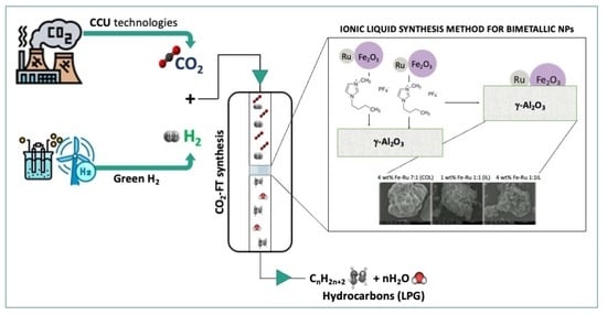
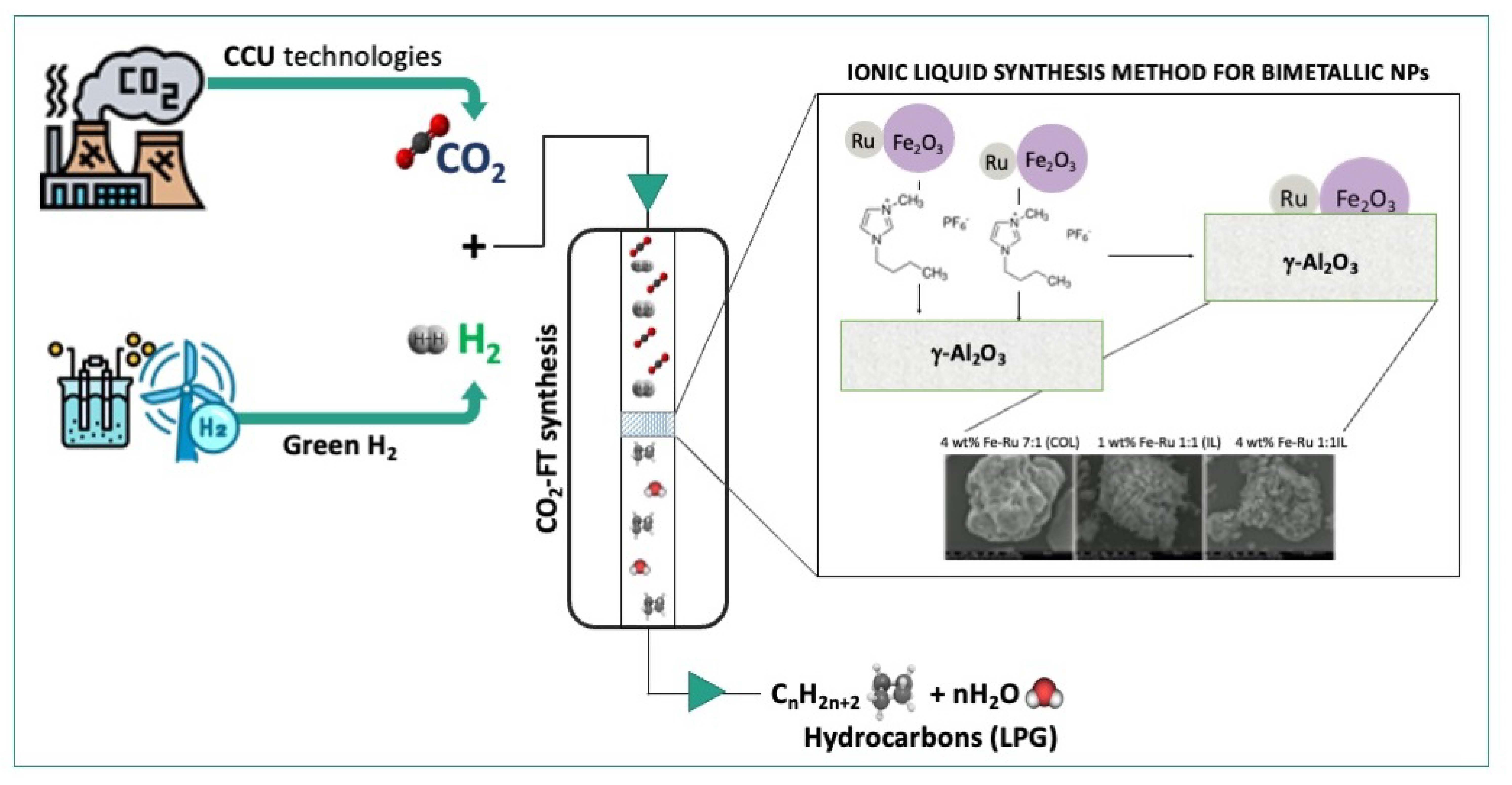
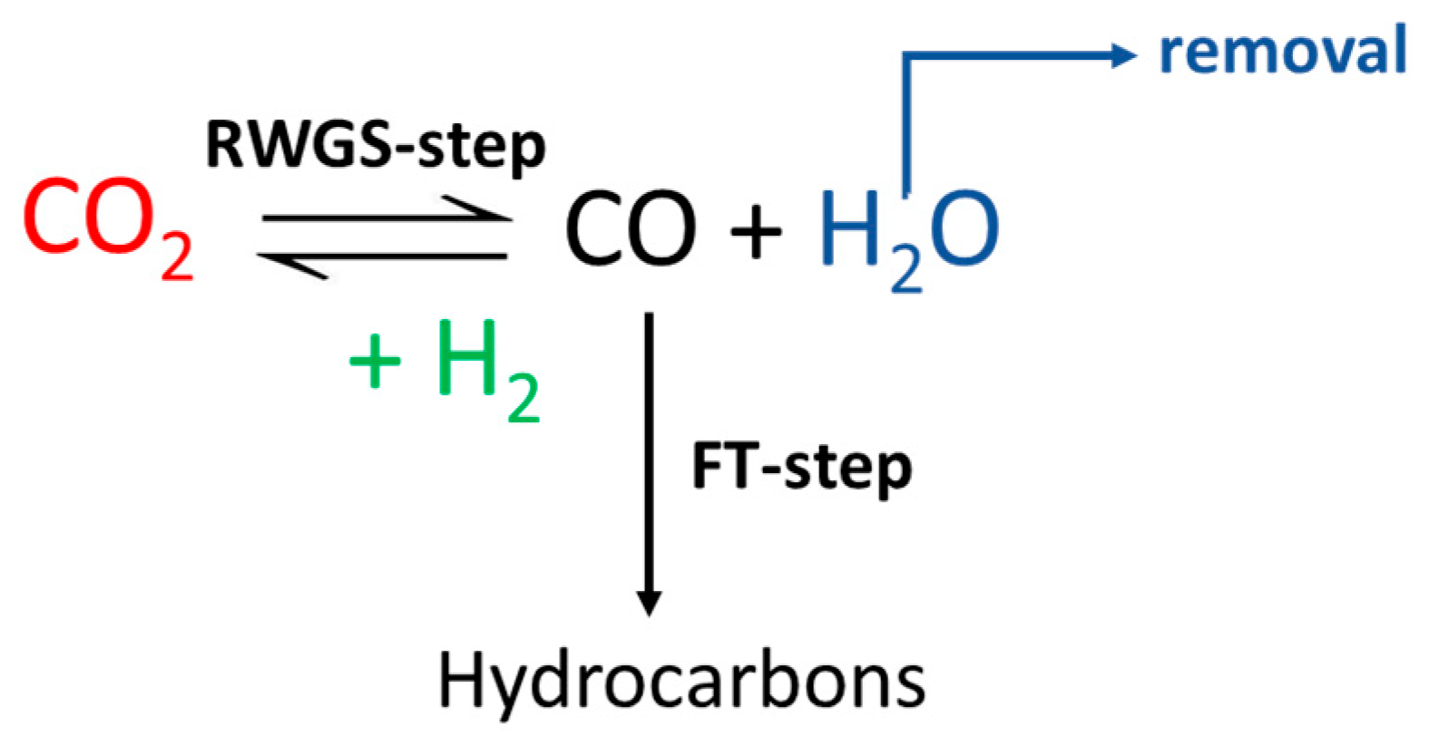
An interesting process for achieving the direct hydrogenation of CO
2 to alkanes and olefins is the so-called “Modified Fischer–Tropsch” synthesis (CO
2-FT) method [
6]. This is a two-step process in which CO
2 is directly converted into CO via the Reverse Water Gas Shift (RWGS) reaction, ultimately producing hydrocarbons through the FT process (
Scheme 1).
The advantage of CO
2-FT synthesis is that both steps occur in the same reactor instead of separately; however, developing an efficient catalyst capable of being active for both FT and RWGS synthesis remains an intriguing challenge. Currently, Fe-based catalysts are utilized in the conventional Fischer–Tropsch reaction, involving the use of a CO + H
2 (syngas) mixture. Recent studies [
7,
8,
9] have indicated that these catalysts can be promising candidates for the CO
2-FT process owing to the low cost of Fe and its satisfactory activity in both steps of the reaction. However, additives can be incorporated into the catalyst to attain high selectivity towards olefins, aiming to create a bimetallic catalyst. In particular, the addition of Ru to Fe-based catalysts has garnered significant attention due to two primary factors: Firstly, Ru is one of the most active metals for FT synthesis; therefore, combining it with Fe is expected to enhance the catalyst’s conversion capabilities. Secondly, combining Ru with Fe modifies the electronic d-band structure, resulting in distinctive catalytic characteristics [
10].
Moreover, the combination of iron and ruthenium in a bimetallic catalyst also facilitates the synthesis of nanoparticles (NPs) in various configurations. For instance, Aitbekova et al. [
11] obtained nanoparticles on the bimetallic catalyst in two forms: as Ru/Fe
2O
3 colloidal heterodimers supported on Al
2O
3, and as a core–shell structure in which Ru is encapsulated by FeOx following reductive pretreatment, with the entire structure deposited on the Al
2O
3 support. They demonstrated that both bimetallic catalysts are effective in converting CO
2 into hydrocarbons in the C
2–C
4 range and CH
3OH, and in particular, the core–shell NPs catalyst exhibited significantly higher hydrocarbon production compared to the Ru/Fe
2O
3/Al
2O
3 heterodimer catalysts at a similar conversion level.
The synergistic effect of bimetallic Ru and Fe active sites on catalyst performance is debated in the literature, and is related to their bimetallic interface and surface structural characteristics. Preparing iron catalysts typically involves saturating a support with two metal salt precursors. However, this may not ensure uniform alloy nanoparticle formation. Bimetallic catalysts often contain iron and ruthenium phases as alloys and separate metal nanoparticles [
10]. Reductions in alumina-impregnated salts generate Fe/Ru alloys and isolated iron and ruthenium nanoparticles, resulting in metal diversity in various phases and oxidation states. This heterogeneity may explain the variable catalytic activity, notably in how ruthenium affects iron-based catalysts in Fischer–Tropsch (FT) reactions. Some studies suggest Ru enhances CO
2 conversion, shifting product distribution to heavier hydrocarbons [
12], while others report no significant Ru impact on activity or selectivity [
13].
It is paramount to achieve the precise and consistent synthesis of stable metal nanoparticles (MNPs) to exert control over the activity of bimetallic catalysts. To address this, we have introduced a novel approach for synthesizing Fe/Ru bimetallic catalysts using ionic liquid solvents. Ionic liquids (ILs), functioning as nanosynthetic templates [
14], enhance MNP stability due to their high ionic charge, strong polarity, elevated dielectric constant, and supramolecular network. Unlike traditional solvents, which mainly consist of neutral molecules, ILs comprise solely charged species, whether these be organic or inorganic ions. They offer new prospects for sustainable and environmentally friendly chemistry, serving as alternatives to volatile organic solvents [
15,
16].
The existing literature has emphasized the utility of ionic liquids for nanoparticle stabilization when synthesizing Ru monometallic nanoparticles and Fe
2O
3 nanoparticles within the ionic liquid [BmIm][BF
4], without requiring additional stabilizers or capping agents. These nanoparticles exhibit an extraordinarily small and uniform size, typically ranging from 1.5 to 2.5 nm [
14].
In continuation of our group’s interest in the development of renewable e-fuel technologies and environmental catalysis [
17,
18,
19,
20,
21,
22,
23,
24,
25], we have developed a novel synthesis method for Fe/Ru bimetallic catalysts using ionic liquids [BmIm][PF
6] and [BmIm][BF
4] as novel solvents for BiMetallic NPs (BMNPs) synthesis. Our method leverages readily available metal carbonyl precursors, facilitating scalability to encompass a wide array of other metal carbonyl complexes. Metal carbonyls are attractive starting materials for nanosynthesis due to their high purity. Furthermore, we utilize readily available low-cost ionic liquids, which are produced in substantial quantities.
Our developed catalyst synthesis method is easily reproducible, and viable for suitable scaling up. The resulting nanoparticles can be easily separated from the ionic liquid, and the ionic liquid can be reused. The nanoparticles can be redispersed in various polar solvents such as acetone, methanol and ethanol, and impregnated onto the final support material, in our case alumina.
The efficacy of our novel synthesis method was assessed through extensive catalytic experiments carried out under diverse conditions, examining its impact on the newly synthetized bimetallic NPs on the catalytic performance in CO2 hydrogenation to short-chain hydrocarbons. The outcomes of these tests have revealed that employing ionic liquids outperformed conventional colloid-based approaches, yielding enhanced conversion rates and higher selectivity towards short-chain hydrocarbons. This achievement underscores the potential of using our innovative methodology in expanding the utilization of ILs for tailored NP synthesis catalysis. Notably, it shows promise in applications involving reactions that are particularly sensitive to metal–metal interactions, such as CO2 hydrogenation for sustainable e-fuel production.
2. Results and Discussion
The morphological characteristics of the catalysts synthesized through colloidal and ionic liquid methods are detailed in
Table 1.
XRF analysis has indicated that both methods successfully achieved catalysts with metal loading amounts close to the theoretical values. In the case of bimetallic samples with 1% w/w loading prepared using the ionic liquid solvent, their surface areas closely resemble those of samples prepared via the colloidal method, ranging from 88 to 95 m2/g, with pore sizes spanning 86–92 Å. However, as the metal loading was increased from 1 to 4%, the surface area decreased to 51 m2/g, accompanied by an increase in the average pore diameter to 109 Å.
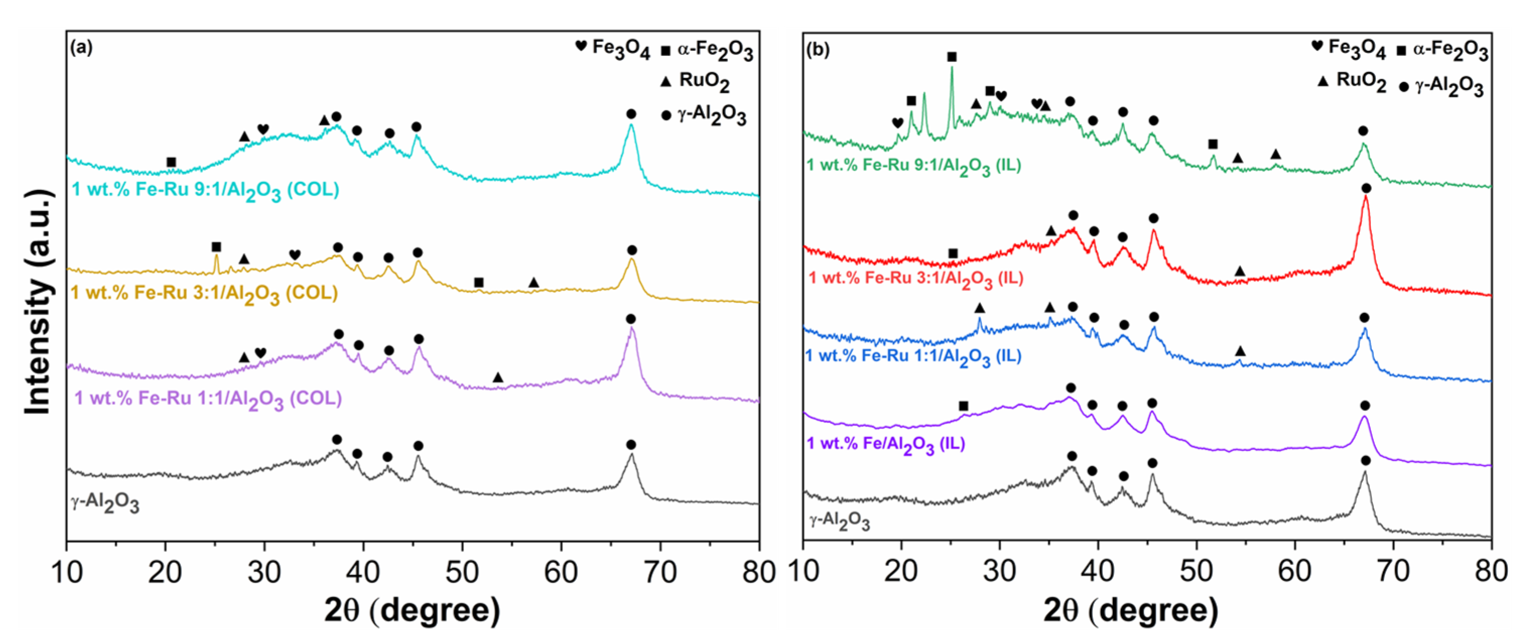
To gain deeper insights into the impact of the new synthetic method on the catalyst’s structure, especially concerning the Fe–Ru ratio, we have first compared the XRD patterns of the fresh catalysts.
In
Figure 1a, we compare three fresh catalysts obtained using the colloidal method, all with identical total metal loadings (1%—see
Table 1) but varying in their Fe:Ru ratios (1:1, 3:1 and 9:1), while in
Figure 1b we illustrate the same comparison between the three bimetallic catalysts (1:1, 3:1 and 9:1) and the monometallic catalysts (1 wt. % Fe/Al
2O
3) obtained via the ionic liquid procedure.
In both cases (IL and COL), the low percentage of metal loading does not allow a clear display of all peaks associated with the presence of iron species. However, the peaks corresponding to the scattering of (012) and (116) planes of α Fe
2O
3 [
26] are visible for both types of catalysts obtained by the two methods, in particular for the catalysts with an Fe–Ru ratio 3:1. These peaks in these samples enable the calculation of the crystallite average size (D
F), which is indicative of nanoparticle dimensions, using the Scherer’s equation [
26]:
where K is the Scherer constant (0.9), λ is the wavelength of the radiation (0.15406 nm), θ is the angle of scattering and β is the FWHM (Full With at Half Maximum).
The obtained results (30.12 nm for 1 wt.% Fe–Ru 3:1/Al
2O
3(COL) and 22 nm for 1 wt.% Fe–Ru 3:1/Al
2O
3(IL)) reveal how the type of treatment employed for catalyst synthesis influenced the resulting nanoparticles, which were smaller in the case of the IL method, possibly justifying greater activity in the FT step. However, in both cases, the size of the nanoparticles falls within the expected range [
27,
28]. This difference is also clearly discernible through a direct comparison of the diffraction patterns between the two catalyst types. In fact, upon examining
Figure 1b alongside
Figure 1a, it becomes evident that in the case of ionic liquids, peaks associated with αFe
2O
3 are more distinctly resolved. Moreover, it is noteworthy that the intensity of these peaks increases proportionally with the rise in the Fe percentage in the catalysts, transitioning from the Fe:Ru ratio of 1:1 to 9:1. In both instances, even more than in the case of iron species, both metallic Ru and RuO
x are either undetected or identified as low-intensity peaks, even in the XRD pattern of the ionic liquid samples, which are generally better resolved. This observation may stem not only from the low total metal loading, but also suggests the high dispersion of Ru species on the support.
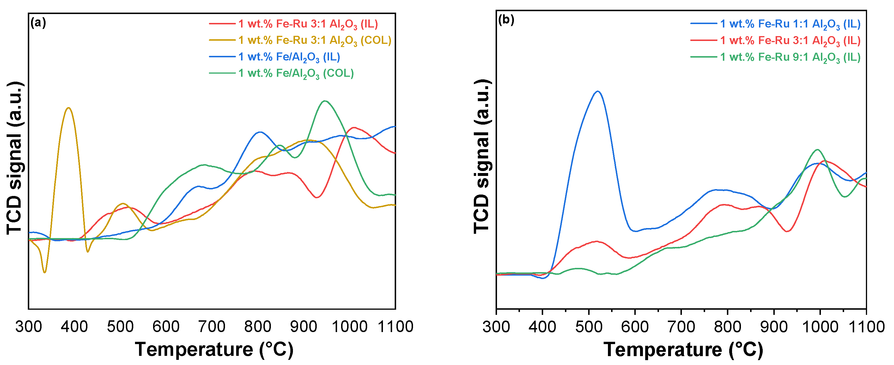
The objective of our study is to compare the catalytic activity of catalysts prepared using different methods (colloidal and ionic liquid). For this purpose,
Figure 2 displays the TPR profiles of the catalysts with different Fe–Ru ratios prepared with the colloidal (
Figure 2a) and ionic liquid methods (
Figure 2b).
The H
2-TPR profiles of Fe
2O
3-RuO
2 catalysts prepared using different methods (colloidal and ionic liquid) are portrayed in
Figure 2 to investigate the difference in the redox performance according to the different reduction profiles with respect to reduction temperature and amount of H
2 consumed for reduction.
In
Figure 2a, the catalysts 1 wt.% Fe–Ru 3:1/Al
2O
3 (COL) and 1 wt.% Fe–Ru 3:1/Al
2O
3 (IL) are reported. In both catalysts, the two reduction peaks associated with Fe
2O
3 are observed. The low-temperature reduction peak, which appeared at approximately 380 °C, was assigned to the reduction of Fe
2O
3 to Fe
3O
4, and the high-temperature reduction peak starting at 620 °C can be assigned to the further reduction of Fe
3O
4 to FeO and Fe
0.
The reduction peaks belonging to Fe
2O
3 in RuO
2–Fe
2O
3 catalysts are shifted to lower temperatures compared with what has been reported in the literature for the pure Fe
2O
3 catalyst [
28]. Moreover, a low-temperature (500 °C) reduction peak is observed in these bimetallic catalysts. This peak could be attributed to the easier reduction of RuO
2 species. This result demonstrates that the addition of RuO
2 accelerated the Fe species reduction, simultaneously revealing the occurrence of hydrogen spillover from Ru atoms to Fe
2O
3 [
28]. Namely, the positive impact of Ru species on the reduction of Fe species illustrates the existence of cooperativity between RuO
2 and Fe
2O
3, which could greatly enhance the reduction property. This result was correlated to the improved catalytic performance. It is noteworthy that a distinct difference between the catalysts obtained using the two different methods is evident even at low temperatures (300 °C < T < 470 °C). Specifically, in the case of the colloidal catalyst, the peak associated with the reduction of Ru
4+ to Ru
0 is highly pronounced [
22,
29,
30]. However, this peak nearly disappears in the case of the IL catalyst. This can be attributed to the presence of a more isolated ruthenium metal phase in the case of catalyst 1 wt.% Fe–Ru 3:1/Al
2O
3 (COL), as opposed to the other sample, where the two metals exhibit a more pronounced synergistic effect due to their closer proximity. Notably, the reduction at 500 °C, attributed to the reduction of RuO
2 associated with Fe [
31], is more prominent in the ionic liquid catalyst.
From the comparison of the reduction profiles among the three IL catalysts with different Fe:Ru ratios (
Figure 2b), it is evident that the peak related to Ru
4+/Ru
0 reduction (T = 470 °C) diminishes when the reduction of ruthenium takes precedence over iron in the catalyst. Furthermore, regardless of the varying ratios of the two metals in the samples, all the distinctive characteristic peaks observed in the colloidal system remain clearly defined. Thus, ionic liquid synthesis improves the reducibility by increasing the cooperativity between Fe and Ru species due to their closer proximity [
31,
32].
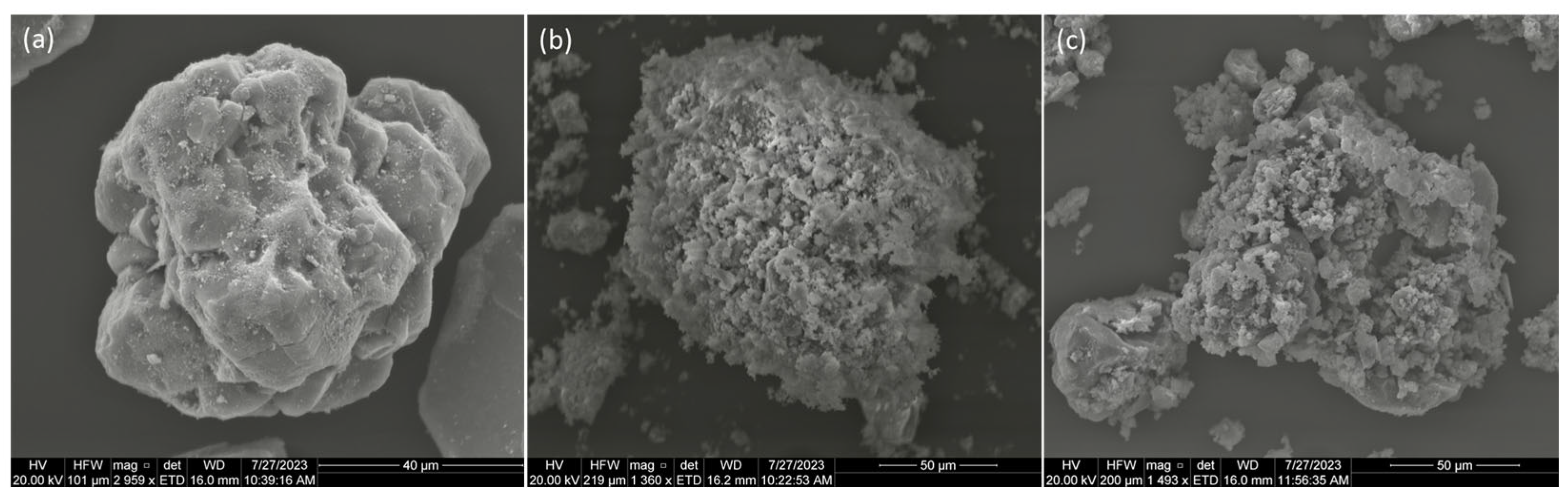
The morphologies of the bimetallic Fe–Ru/Al
2O
3 catalysts prepared using colloidal and ionic liquid methods with varying Fe:Ru ratios were characterized using SEM analysis (
Figure 3).
It can be seen from
Figure 3a that the particles of the catalyst prepared using the colloidal method, 4 wt.% Fe–Ru 7:1/Al
2O
3 (COL), are large with an irregular morphology and a smooth surface. In contrast, the catalyst particles prepared using the ionic liquid method, for instance, 1 wt.% Fe–Ru 1:1/Al
2O
3 (IL) (
Figure 3b) and 4 wt.% Fe–Ru 1:1/Al
2O
3 (IL) (
Figure 3c), show agglomerates of numerous smaller nanoparticles, with irregular but rough surfaces.
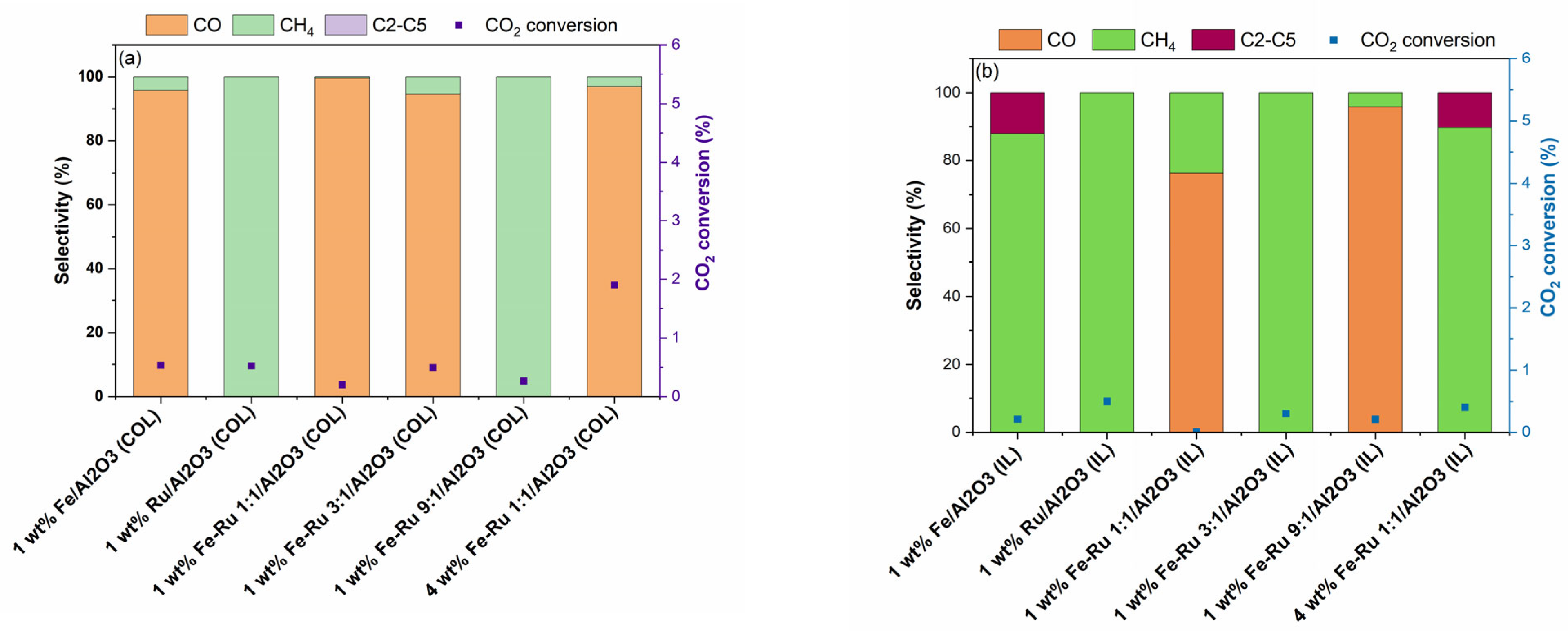
Finally, activity experiments at a single temperature of 320 °C and GHSV of 5400 mL/h/gcat, and at two pressures of 20 bar (
Figure 4 and
Figure 5) and 6 bar (
Figure 6), were carried our for each synthesized catalyst. High pressure test conditions are closer to industrial settings, where high pressures are often employed, and low pressures have been investigated for screening purpose. Although CH
4 is the primary expected product at these conditions, the information gathered via these experiments is invaluable for comparing the activity and selectivity of the catalysts prepare via the two different synthetic routes [
11].
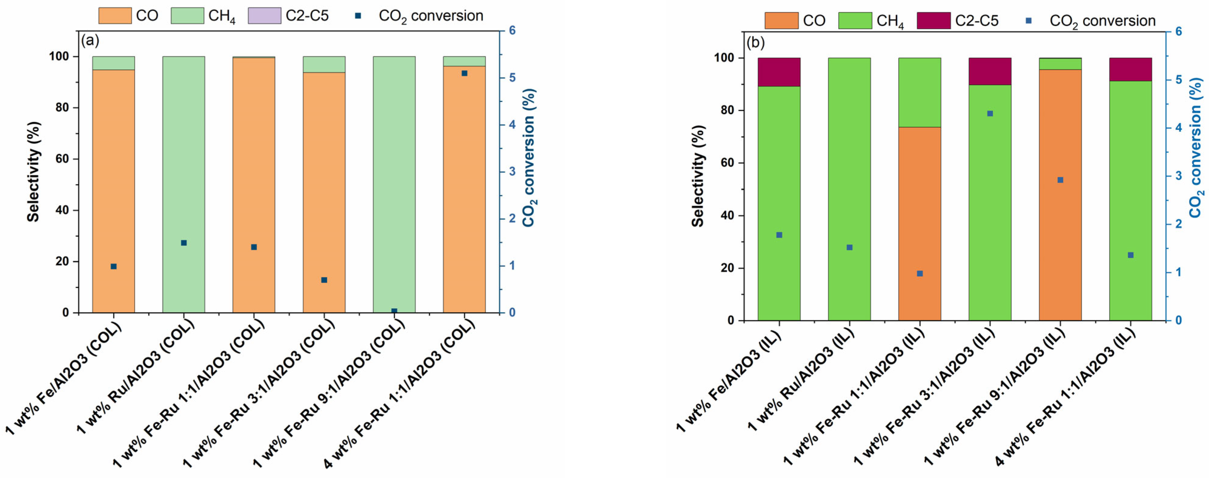
The results of activity tests in the hydrogenation of CO
2 at 20 bar total pressure and 45 mL/min are summarized in
Figure 4.
As shown in
Figure 4a for COL samples and
Figure 4b for IL samples, when using 1 wt.% Fe/Al
2O
3 catalysts prepared using COL and IL synthesis methods, distinct selectivity profile was observed. When using 1 wt.% Fe/Al
2O
3 (COL) catalyst, CO was obtained as the major product, while when using 1 wt.% Fe/Al
2O
3 (IL) catalyst, selectivity shifted from CO to CH
4 and C
2–C
5 hydrocarbons. However, the 1 wt.% Ru/Al
2O
3 catalysts prepared using both COL and IL synthesis methods showed similar product profiles with 100% selectivity to CH
4. When comparing the bimetallic 1 wt.% Fe–Ru 1:1/Al
2O
3 catalysts, while COL catalyst showed high selectivity to CO, the IL catalyst showed a shift in product selectivity, resulting in the mixture of CO and CH
4. The observed shift in product selectivity was more prominent when the total metal loading was increased from 1 wt.% to 4 wt.%. While the 4 wt.% Fe–Ru 1:1/Al
2O
3 (COL) catalyst showed CO as the major product, the 4 wt.% Fe–Ru 1:1/Al
2O
3 (IL) catalyst showed CH
4 and C
2–C
5 hydrocarbons as major products.
It is widely acknowledged that CO
2 is reduced to CO via the RWGS reaction on the Fe
3O
4 active sites, while the presence of Fe
5C
2 facilitates the FT reaction for the formation of hydrocarbons. To investigate the influence of the catalyst synthesis method on the formation of active sites, we further carried out the XRD characterization of the spent catalysts prepared by both COL and IL methods (
Figure S1). For instance, the 1 wt.% Fe–Ru 1:1/Al
2O
3 (COL) catalyst (
Figure S1a) indicated the presence of Fe
2O
3 and Fe
3O
4, while both 1 wt.% Fe/Al
2O
3 (IL) and 1wt.% Fe–Ru 1:1/Al
2O
3 (IL) catalysts clearly depicted the presence of Fe
5C
2, indicating that Fe
3O
4 was fully carburized to Fe
5C
2. It is worth noting that this iron carbide phase plays a key role in the subsequent C–C chain growth reaction. Thus, it is noticeable that the catalyst synthesis method has a strong influence on the ultimate structure of the catalyst active sites. From the structure–activity correlation determined from the XRD analysis of fresh and spent catalysts and observed product selectivity profiles, it is noticeable that the ionic liquid synthesis method facilitates the formation of Fe
5C
2 species, which facilitate the FT reaction, promoting the formation of C
2–C
5 hydrocarbons.
The influence of space velocity at 20 bar total pressure was evaluated by performing the hydrogenation of CO
2 at 15 mL/min, and the results are summarized in
Figure 5.
As shown in
Figure 5a,b, when using 1 wt.% Fe/Al
2O
3 catalysts prepared using the COL and IL synthesis methods at 1800 mL/h/gcat, a similar shift in selectivity profile was observed, as seen previously at 5400 mL/h/gcat (
Figure 4), albeit higher CO
2 conversions were observed at lower GHSV values, which is expected due to the increased residence time. When comparing the bimetallic 1 wt.% Fe–Ru 1:1/Al
2O
3 catalysts, higher CH
4 and C
2–C
5 hydrocarbon selectivity values were observed with the catalyst synthesized using the IL method. Amongst the bimetallic catalysts, 1 wt.% Fe–Ru 3:1/Al
2O
3 (IL) showed the highest conversion and C
2–C
5 hydrocarbon selectivity, indicating the most optimal catalytic performance.
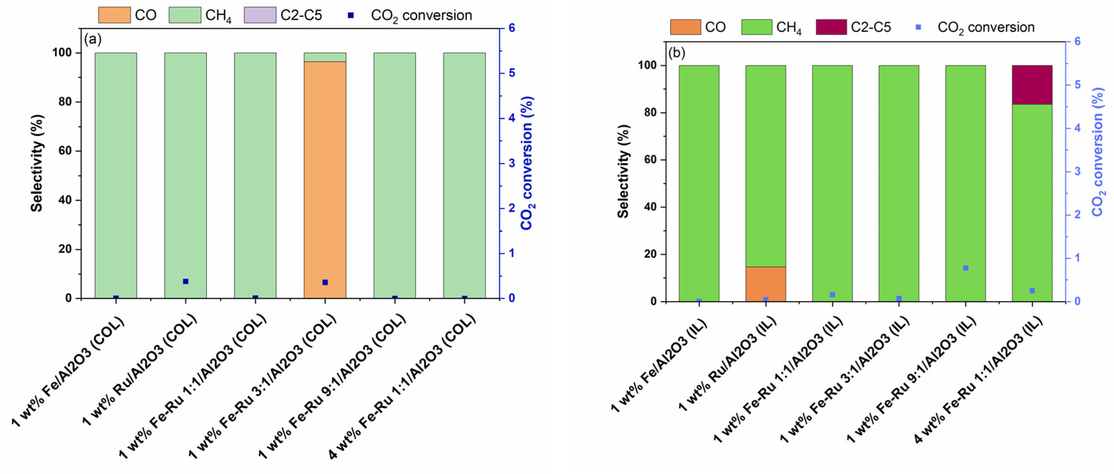
The effect of total pressure on the product selectivity was evaluated via the hydrogenation of CO
2 at 6 bar pressure and 5400 mL/h/gcat. The results of activity tests at 6 bar and 45 mL/min are summarized in
Figure 6.
As shown in
Figure 6a,b, when using 1 wt.% Fe/Al
2O
3 catalysts prepared using both COL and IL synthesis methods at 6 bar total pressure, 100% selectivity to CH
4 was observed, albeit with lower CO
2 conversions. Similarly, bimetallic 1 wt.% Fe–Ru 1:1/Al
2O
3 catalysts prepared using both COL and IL methods displayed similarly high CH
4 selectivity. While the 4 wt.% Fe–Ru 1:1/Al
2O
3 (COL) catalyst showed CH
4 as the only product, the 4 wt.% Fe–Ru 1:1/Al
2O
3 (IL) catalyst showed CH
4 as major product, with excellent hydrocarbons selectivity of 16.5% to C
2–C
5, and 83.5% selectivity to CH
4.
3. Materials and Methods
3.1. Materials
Triruthenium dodecacarbonyl (Ru3(CO)12, 99%), Tris(acetylacetonato)iron(III) (Fe(acac)3. 97%, Iron(0) carbonyl (Fe(CO)5), >99.99%), 1-oleylamine (OLAM, 90%), and 1-octadecene (ODE, 99%) were purchased from Merck (Darmstadt, Germany), and oleic acid (OLAC, 99%) was purchased from Thermo Scientific Chemicals™ (Waltham, MA USA). The alumina used as support was γ-Al2O3 (S.A. 100 m2/g, 99.9%), purchased from Thermo Scientific Chemicals. All solvents were of analytical HPLC grade and all reagents were used as received. All calcined supports and samples were ground and sieved below 180 μm grain size.
3.2. Synthesis of NPs
Ru nanoparticles were synthesized via colloidal synthesis by the thermal decomposition of Ru
3(CO)
12 using a standard Schlenk technique with slight modifications (Aitbekova et al., 2019) [
11]. In a 2-neck flask, 100 mg of Ru
3(CO)
12 and 20 mL of oleylamine were combined, degassed under vacuum and argon, heated to 270 °C, and maintained for 30 min. After cooling and adding 15 mL of ethanol, the nanoparticles were isolated by centrifugation at 4400 rpm for 3 min and dispersed in 10 mL of hexane. Fe nanoparticles were prepared following the same protocol, using 10 mL of oleylamine and 1 mmol of Fe(acac)
3, dehydrated at 110 °C, rapidly heated to 300 °C, and aged for 1 h. After washing with ethanol, the solid metal nanoparticles were recovered and dispersed in 10 mL of hexane. Bimetallic Ru–Fe nanoparticles were synthesized from a hexane solution containing previously prepared ruthenium nanoparticles, along with 1-octadecene (ODE), oleic acid (OLAC), and oleylamine (OLAM). After degassing for 30 min at 120 °C under a continuous flow of nitrogen and the careful injection of Fe(CO)
5, the mixture was heated to 300 °C for 30 min. Following two washing steps, initially with isopropyl alcohol, followed by dispersion in 5 mL of hexane, and then with the addition of 10 mL of ethanol, the nanoparticles were separated through centrifugation (4400 rpm for 3 min) and dispersed in hexane.
In the ionic liquid (IL)-assisted method for synthesizing nanoparticles, 5 g of [BmIm][BF4] and 337 mg of Fe(acac)3(for Fe oxide NPs) or 105 g of Ru3(CO)12 (for Ru NPs) were utilized in separate reactions. For the Fe oxide NPs, the mixture was heated to 200 °C for 16 h under argon, followed by the addition of 20 mL of ethanol for nanoparticle separation through centrifugation at 8000 rpm. The isolated iron oxide nanoparticles were then dispersed in 15 mL of ethanol. Similarly, for Ru NPs, the solution was maintained at 250 °C for 18 h, and after adding 15 mL of ethanol, the particles were separated via centrifugation and redispersed in 15 mL of ethanol.
For the bimetallic Fe–Ru NPs, three different molar ratios were examined: 1:1, 3:1 and 9:1. In all cases, a controlled environment within a glove box was used, with Fe(acac)3 and Ru3(CO)12 meticulously introduced into [BmIm][PF6]. After undergoing appropriate reductions at 250 °C for 18 h, the resulting nanoparticles were deposited onto the support material. For the 1:1 ratio, 95 mg of Fe(acac)3 and 65 mg of Ru3(CO)12 were employed, while for the 3:1 ratio, approximately 106.5 mg of Fe(acac)3 and approximately 23 mg of Ru3(CO)12 were used. Finally, for the 9:1 Fe–Ru NPs, 152 mg of iron precursor and 12 mg of ruthenium precursor were mixed with 3 g of ionic liquid, and the solution was heated to 200 °C for 18 h before direct deposition onto the support material. This approach aimed to minimize nanoparticle aggregation during dispersion in polar solvents, and to ensure effective deposition on the alumina support.
3.3. Catalyst Preparation
In the colloidal method for supporting nanoparticles on γ-Al2O3, both Fe and Ru NPs were prepared similarly. An appropriate quantity of different types of NPs was added to the γ-Al2O3 support dispersed in hexanes under vigorous stirring (30 min at 1400 rpm) to achieve a total metal loading of 1 or 4 wt.%. Afterward, centrifugation at 4000 rpm for 3 min separated the solid phase, which was then dried at 80 °C for 4 h to eliminate organic residues and sieved using a 150 μm sieve. Additionally, for the preparation of Ru–Fe oxide NPs on γ-Al2O3, TGA analysis indicated a yield of 5.1 mg (Fe + Ru)/mL, requiring approximately 4 mL of solution to introduce 20 mg of metal (1% relative to 2 g of γ-Al2O3). The subsequent steps of the procedure were consistent with those employed for Fe and Ru NPs, involving hexane addition, agitation, centrifugation, drying, and sieving using the same mesh size.
Regarding the supporting method on γ-Al2O3 for catalysts synthesized with ionic liquids (ILs), the IL with dispersed metallic NPs solution was cooled to 75 °C to increase the ionic liquid’s viscosity. Subsequently, 10 mL of ethanol was added, and the solution underwent centrifugation for 10 min at 8000 rpm to separate the solid NPs from the liquid phase. After several washes with ethanol, the particles were deposited in a mortar. Following the addition of the desired amount of alumina, the powder was mechanically agitated and ground for 15–20 min to achieve a uniform color and metal distribution. Finally, the resulting catalyst was dried at 80 °C to remove residual organics and calcined to complete the process.
All the obtained catalysts are reported in
Table 1, detailing the synthetic method, the total metal loading, and the Fe:Ru ratio
3.4. Catalyst Characterization
X-ray fluorescence (XRF) spectroscopy (Horiba, Kyoto, Japan) was used to determine the elemental composition of the catalysts prepared with colloidal and ionic liquid synthesis.
Table 1 shows the actual composition of each element compared to the calculated amount.
The textural properties of the synthesized samples have been determined by N2 adsorption–desorption isotherms measured at −196 °C using the Micromeritics Tristar 3000 instrument (Norcross, GA, USA). Prior to the analysis, the samples were evacuated at 120 °C for 3 h.
Powder X-ray diffraction (XRD) (Rigaku, Tokyo, Japan)analysis of the fresh and spent catalysts was carried out using a D8 Advance Bruker® diffractometer (Billerica, MA, USA) with Cu–Kα radiation, l = 1.5405 Å. The measurements were taken from 20 to 90 degrees (2θ) at a scan rate of 0.01° per step and a scan time of 0.5 s−1 per step.
The reducibility of calcined FeRu catalysts was investigated by the temperature programmed reduction (TPR) technique in H2 (H2-TPR). In a typical test, the powdered catalyst was placed in a quartz reactor and, after a pre-treatment in flowing 10% O2/He (35 mL/min) carried out by heating from ambient temperature to 500 °C at a rate of 20° C/min, was cooled down to −10 °C. Then, the flow was switched to 5 vol.% H2 in Ar at 53 mL/min and the reactor temperature was increased to 900 °C at 10 °C/min. Hydrogen consumption was monitored by a thermal conductivity detector (TCD) placed downstream of the reactor, after a cold trap.
Scanning electron microscopy (SEM) analysis was performed using FEI Quanta FEG 200 environmental SEM (Hillsboro, OR, USA) in a high-vacuum mode with EDX accessories attached. Prior to the measurement, the sample in powder form was sprinkled on carbon tape (adhesive) and mounted on the SEM sample holder.
3.5. Catalytic Activity Testing
Activity tests were carried out in a lab-scale plant equipped with a fixed-bed reactor. Approximately 500 mg of catalyst powder was diluted with Al2O3 in a 1:10 dilution ratio, and this was physically mixed and loaded into the reactor between two layers of quartz wool. The reactor was heated using a Carbolite-Gero MTF single zone tube furnace (Derbyshire, UK) while the catalyst bed temperature was measured using a K-type thermocouple inserted in the middle of the reactor bed. The reaction mixture consisted of 3:1 H2:CO2. Kinetic experiments were conducted at 320 °C, and at 6 and 20 bar total pressure with a gas-hourly space velocity (GHSV) of 5400 mL/h/gcat. Catalytic tests were also repeated at the same temperature, 320 °C, at 20 bar total pressure and a GHSV of 1800 mL/h/gcat, to assess the effect of spatial velocity on the catalyst performance. Prior to catalytic activity testing, each catalyst was pretreated in pure H2 at 400 °C for 5 h with a temperature ramp rate of 2 °C min−1. The outlet reactor stream was analyzed to determine CO2 conversion and product selectivity using a GC (Agilent, 8860, Santa Clara, CA, USA) equipped with a TCD detector connected to a packed column along with a FID detector connected to CP-Sil PONA column along with a FT-IR gas analyzer (Bruker®, MATRIX-MG5, Billerica, MA, USA).


 ,
, 


