Article

Synthesis of Magnetic α-Fe2O3/Rutile TiO2 Hollow Spheres for Visible-Light Photocatalytic Activity

1
College of Physics, Qingdao University, No. 308 Ningxia Road, Qingdao 266071, China
2
State Key Laboratory of Bio Fibers and Eco Textiles, Qingdao University, No. 308 Ningxia Road, Qingdao 266071, China
3
National Engineering Research Center for Intelligent Electrical Vehicle Power System, Qingdao University, No. 308 Ningxia Road, Qingdao 266071, China
4
School of Mechanical and Electrical Engineering, Qingdao University, No. 308 Ningxia Road, Qingdao 266071, China
5
National Institute for Materials Science, 1-2-1 Sengen, Tsukuba 3050047, Japan
*
Authors to whom correspondence should be addressed.
Catalysts 2021, 11(3), 396; https://doi.org/10.3390/catal11030396
Submission received: 15 February 2021 / Revised: 15 March 2021 / Accepted: 16 March 2021 / Published: 20 March 2021
(This article belongs to the Section Photocatalysis)

Abstract

:
The high recombination rate of the electron-hole pair on the surface of rutile TiO2 (RT) reduces its photocatalytic performance, although it has high thermodynamic stability and few internal grain defects. Therefore, it is necessary for RT to develop effective methods to reduce electron-hole pair recombination. In this study, magnetic α-Fe2O3/Rutile TiO2 self-assembled hollow spheres were fabricated via a facile hydrothermal reaction and template-free method. Based on the experimental result, phosphate concentration was found to play a crucial role in controlling the shape of these hollow α-Fe2O3/RT nanospheres, and the optimal concentration is 0.025 mM. Due to a heterojunction between α-Fe2O3 and RT, the electron-hole pair recombination rate was reduced, the as-synthesized hollow α-Fe2O3/RT nanospheres exhibited excellent photocatalysis in rhodamine B (RhB) photodegradation compared to α-Fe2O3 and RT under visible-light irradiation, and the degradation rate was about 16% (RT), 60% (α-Fe2O3), and 93% (α-Fe2O3/RT) after 100 min. Moreover, α-Fe2O3/RT showed paramagnetism and can be recycled to avoid secondary environmental pollution.

1. Introduction

Semiconductor photocatalysis is an advanced environmental purification technology that converts solar energy into chemical energy [1,2,3,4]. This promising technology can oxidize organic pollutants through superoxide anions or hydroxyl radicals produced by photo-electrons or photo-generated holes [5,6]. Titanium dioxide (TiO2), as a typical photocatalytic material, has excellent photocatalytic properties. Many studies have shown that the photocatalytic activity of anatase crystal TiO2 is much greater than that of rutile crystal, and it has received extensive attention and applications [7,8]. Theoretically, compared with the anatase crystal form, the rutile crystal form TiO2 has higher thermodynamic stability and fewer internal grain defects. However, it does not show comparable photocatalytic performance. One of the main reasons is that rutile TiO2 has a high carrier recombination rate, limiting its photocatalytic activity. Therefore, how to improve the separation efficiency of photogenerated carriers of rutile TiO2 is an urgent problem to be solved [9,10,11].
Compared with anatase TiO2 (AT), RT has a relatively narrow bandgap and can absorb more solar energy than AT in the near-ultraviolet region (wavelength: 360–400 nm) [12]. However, since electron-hole pairs are easy to recombine, the photocatalytic performance is affected. To address this issue, researchers have done a lot of work. For example, the enhancement of photocatalytic performance of TiO2 by using various strategies such as doping, semiconducting heterojunction, heterostructure [13], and anatase-rutile combination has been successful. Xu et al. [14] synthesized rutile/anatase TiO2 heterojunction nanoflowers via a facile one-step hydrothermal approach, which showed excellent stability. Researchers introduced low band gap materials with TiO2 heterojunctions, designed nanomorphologies to improve the charge separation, increase active sites, etc., in their work. Ghosh et al. [15] reported a set of mesoporous, hierarchical “nanorods-on-nanofiber” heterostructures produced from the organization of V2O5 nanorods on TiO2 nanofibers fabricated using a gas jet fiber spinning process. Zhang et al. [16] fabricated a novel three-dimensional Fe2O3 nanorod/TiO2 nanosheet heterostructure via the facile hydrothermal and chemical bath deposition methods and this structure exhibited the superior photocatalytic. Semiconductor hematite (α-Fe2O3), with a bandgap between 1.9 and 2.2 eV, is usually thermodynamically stable and can be used as a photocatalyst to decompose water and degrade organic pollutants [17]. α-Fe2O3 has strong visible light absorption, stability, and other advantages, such as magnetism, recyclability, and no secondary pollution for the environment. However, due to its low carrier mobility and the short excited-state lifetime, α-Fe2O3 usually exhibits weaker photocatalytic performance [18]. Therefore, we combined RT with visible light-responsive α-Fe2O3 to form a heterojunction. The excitable electrons on the α-Fe2O3 conduction band (CB) can be transferred to the RT’ valence band (VB) across the barrier, which can improve the electron transfer ability of α-Fe2O3 and extend the lifetime of excited electrons. The holes on the RT are transferred to α-Fe2O3, making up for the deficiency of the high recombination rate of RT electron holes, enhancing charge separation, and improving photocatalytic performance.
Luan et al. [9] synthesized RT nanorod-coupled α-Fe2O3 by a wet-chemical process, which confirmed that the coupling of an appropriate amount of RT nanorods with α-Fe2O3 could significantly enhance the feasibility of photoelectron chemical oxidation and degradation of pollutants. The researchers also confirmed that RT combined with visible light-responsive Fe2O3 can effectively increase the light absorption range and improve photocatalytic activity. Wang et al. [19] synthesized the mesoporous Fe2O3/ TiO2 heterostructure microspheres by the solvothermal method and optimized the preparation conditions. Liu et al. [20] prepared 3D α-Fe2O3@ TiO2 core-shell nanocrystals with three forms—rhombic, cubic, and disc-shaped—through hydrothermal and annealing processes. Xie et al. [21] developed a feasible route to enhance the visible photocatalytic activities of α-Fe2O3 nanoparticles for degrading colorless pollutants by coupling a proper amount of mesoporous nanocrystalline AT. Most researchers take α-Fe2O3 as the magnetic core and load TiO2 onto its surface to form a core-shell structure. However, this structure may affect the magnetism of α-Fe2O3 because of the excessively thick TiO2 loading, and it is difficult for α-Fe2O3 and TiO2 to have a synergistic effect and improve the photocatalytic performance. The spherical hollow structure has been widely studied because of its advantages, such as high specific surface area, low density, high load-bearing capacity, and high refractive index [22,23,24,25,26].
Herein, we first synthesized an RT and α-Fe2O3 composite with a spherical hollow structure via a one-pot hydrothermal method without the template. The self-assembled hollow structures have a heterojunction structure that can effectively improve the photocatalytic activity. The morphology of the assembled structure is controlled by adjusting the amount of phosphate ion and proposes a possible reaction mechanism. We also explored the growth mechanism of hollow self-assembled composite structures through time-variable experiments. The obtained magnetic hollow self-assembled composite structure has enhanced photocatalytic activity, can be mass-produced, and can be recycled. Our synthetic method makes RT have potential application value in the field of photocatalytic degradation of organic pollutants.

2. Results and Discussion

2.1. Characterization

The XRD patterns (Figure 1) show the purity and crystallinity of the synthesized sample. Several peaks were observed in the positions of 24.13°, 33.15°, 35.61°, 40.85°, 49.17°, 54.08°, 62.44°, and 63.98° in the XRD patterns of α-Fe2O3/RT samples, which were indexed to the (0 1 2), (1 0 4), (1 1 0), (1 1 3), (0 2 4), (1 1 6), (2 1 4), and (3 0 0) crystal planes of α-Fe2O3 (PDF 87-1165) [16]. Regarding the peak of RT, 27.44° corresponded to the (1 1 0), (1 0 1), (1 1 1), (2 1 1), and (3 1 0) crystal planes of RT (PDF 76-1941) [14]. According to the full width at half-maximum (fwhm) of the diffraction peaks, the average crystallite size of the α-Fe2O3 crystallites (phosphate addition of 0 mM, 0.025 mM, and 0.042 mM) could be estimated from the Scherrer equation to be about 420.3, 375.4, and 401.2 nm, respectively; the average crystallite size of the RT crystallites (phosphate addition of 0 mM, 0.025 mM, and 0.042 mM) could be estimated from the Scherrer equation to be about 468.5, 450.3, and 474.2 nm, respectively.
Dhkl = Kλ/(βhkl cos θhkl)
where Dhkl is the particle size perpendicular to the normal line of the (hkl) plane, K is a constant (0.89), βhkl is the full width at half-maximum of the (hkl) diffraction peak, θhkl is the Bragg angle of (hkl) peak, and λ is the wavelength of the X-ray. No other peaks were observed, demonstrating that the α-Fe2O3 and RT had high purity and high crystallinity, which are advantageous for enhancing the photocatalytic activity under visible light irradiation.
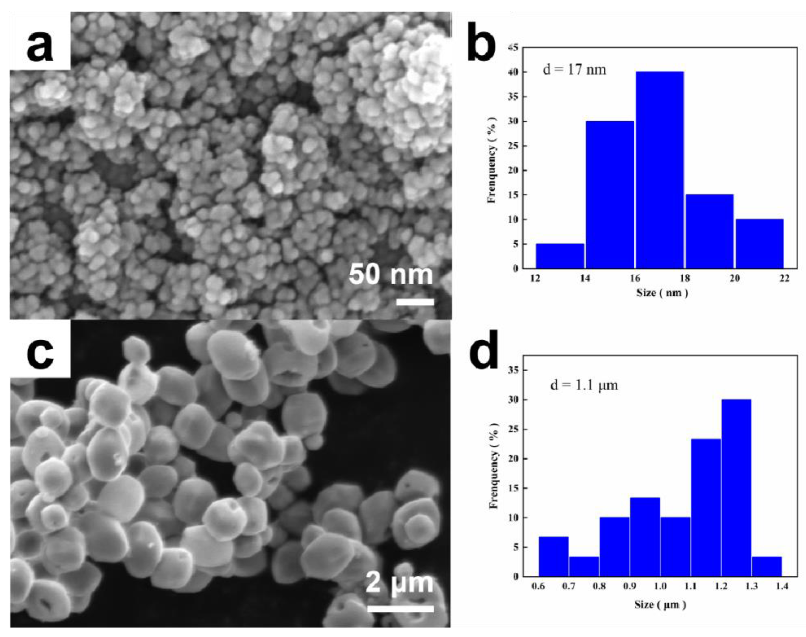
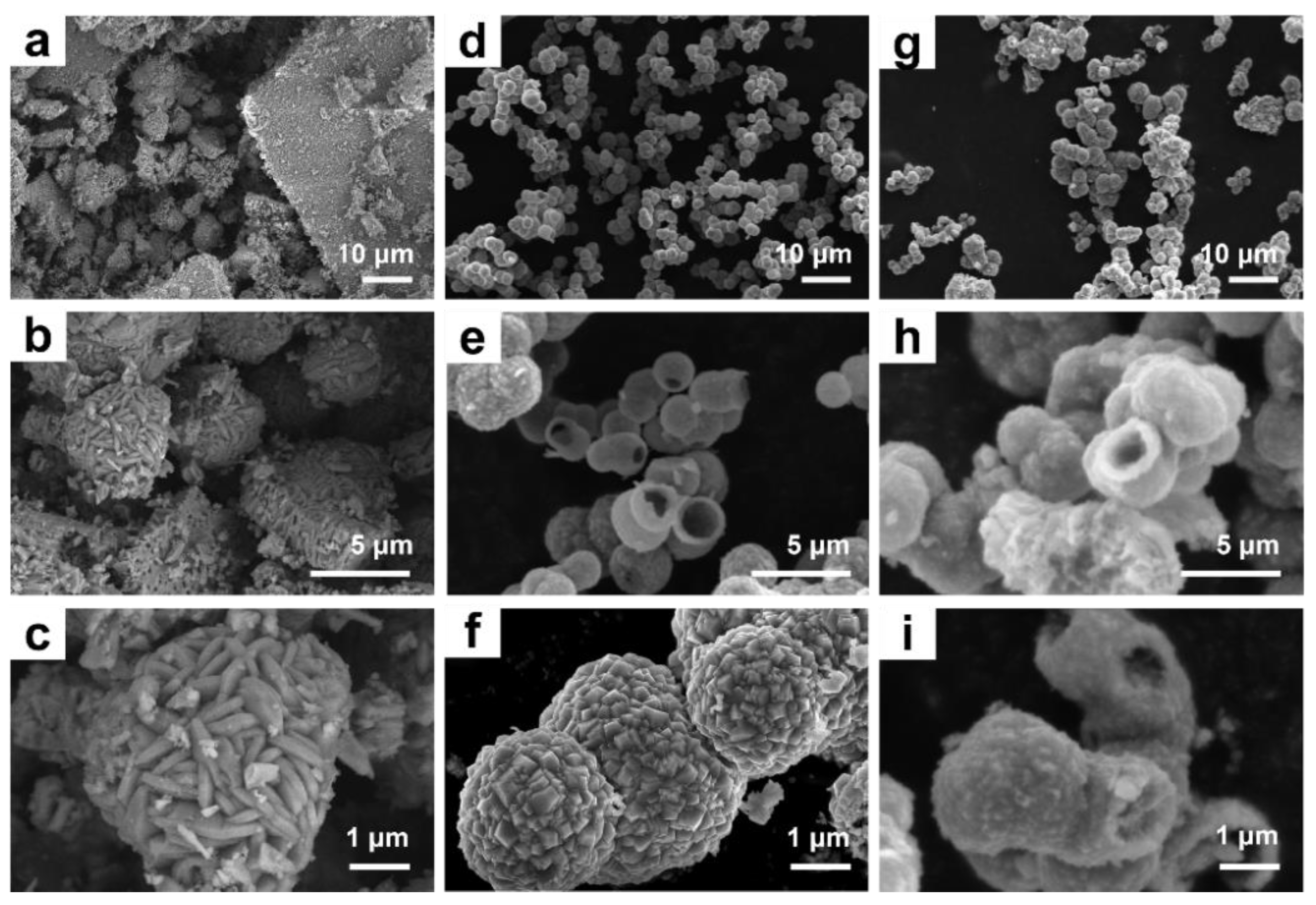
The morphology of pure RT and α-Fe2O3 is shown in Figure 2. The agglomeration of all particles was severe. Sufficient active sites could not be exposed, which was not conducive to photocatalytic reactions and reduced photocatalytic activity. In addition, RT (Figure 2a) had a spherical structure with an average particle size of 17 nm according to the histogram of the particle size distribution (Figure 2b), and α-Fe2O3 (Figure 2c) was an ellipse with an average particle size of 1.1 μm (Figure 2d). Figure 3a–c are the SEM images of α-Fe2O3/RT (0 mM) with many agglomerated particles. When the phosphate concentration was up to 0.025 mM (Figure 3d–f), hollow α-Fe2O3/RT nanospheres were formed and assembled by pyramid-shaped particles. As shown in Figure 3e, some broken α-Fe2O3/RT microspheres revealed that the as-obtained α-Fe2O3/RT nanospheres were of the hollow structure. Figure 3g–i SEM images of α-Fe2O3/RT (0.042 mM) show that the sample’s shell became thicker than the addition of 0.025mM α-Fe2O3/RT, and the morphology of the assembled unit became irregular.
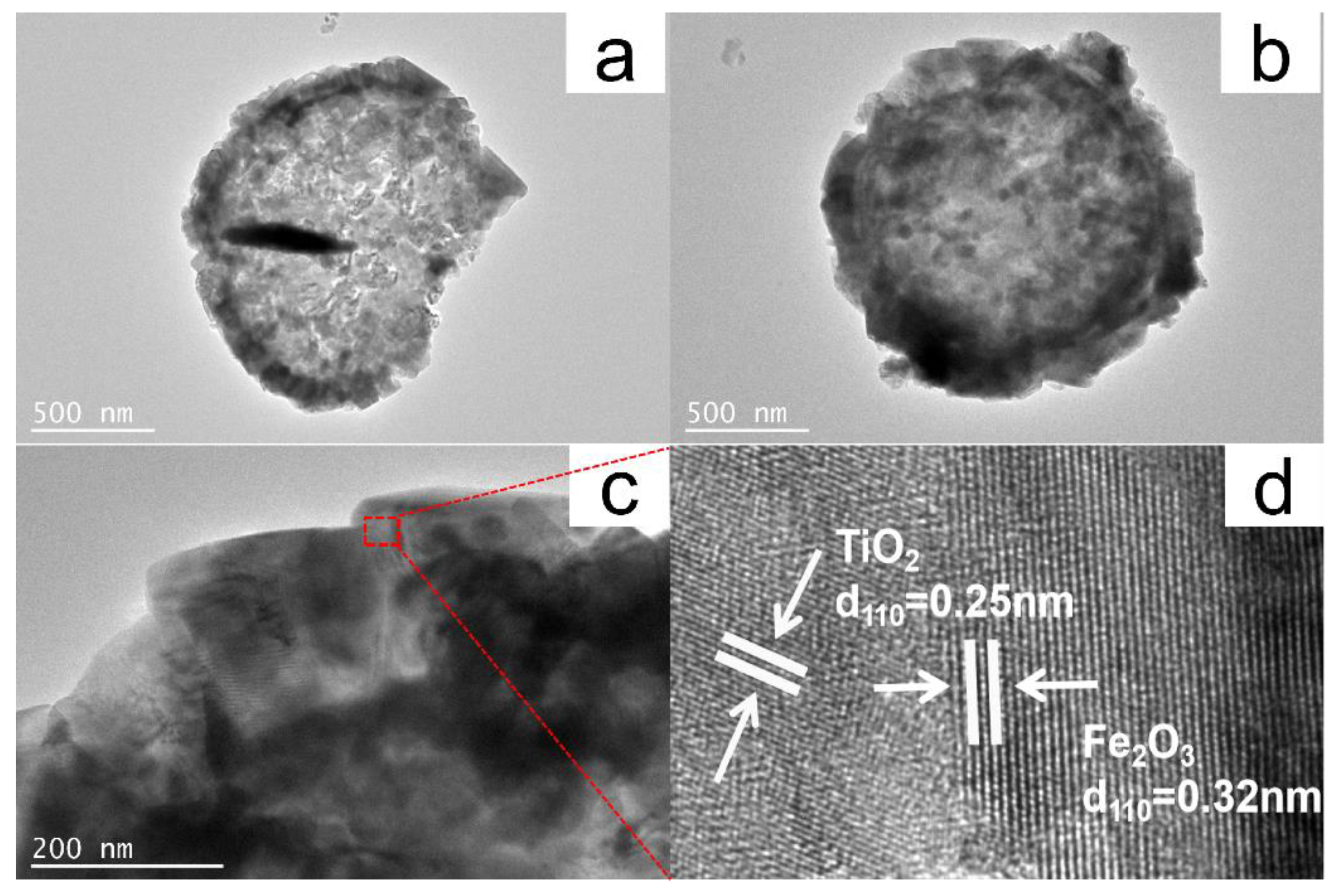
To further understand the composition of α-Fe2O3/RT, we performed an EDX analysis, as shown in Figure 4. Fe, Ti, and O were evenly distributed on the sphere. Figure 5a–c are the typical TEM images of α-Fe2O3/RT (phosphate addition was 0.025 mM) nanospheres (about 1.5 μm) with hollow structures assembled by nanoparticles. Furthermore, the intimate heterojunctions between α-Fe2O3 and RT were formed utilizing the High Resolution Transmission Electron Microscope (HRTEM) image (Figure 5d). The facet distances of 0.32 nm and 0.25 nm corresponded to the α-Fe2O3 (1 1 0) [9] crystal plane and RT (1 1 0) [27] crystal plane, respectively. The clear stripes show that the composite material had good crystallinity. This heterojunction structure was conducive to electron transfer.
As expected, the composite hollow structure’s morphology could be controlled by adjusting the concentration of phosphate ions (H2PO4). The introduction of H2PO4 reduces the pH of the reaction system. A low pH can suppress the dissolution of the intermediate product α-FeOOH substrate [28,29,30,31]. Since the slow dissolution of an α-FeOOH substrate promotes α-Fe2O3 nucleation, the addition of H2PO4 anions may promote the directional aggregation growth process of α-Fe2O3 nuclei. In short, H2PO4- plays an essential role in the formation of the hollow sphere α-Fe2O3/RT, and a complete spherical structure cannot synthesize without H2PO4 due to the nucleation of α-Fe2O3 being inhibited. However, when H2PO4 is excessive, H2PO4 can decrease the concentration of α-Fe2O3 in the solution by promoting Equation (1) towards the right [32]. Therefore, much damage occurred to the spherical structure. Therefore, H2PO4 affected the sample particles’ structure, which further affected the photocatalytic performance of α-Fe2O3/RT.
Fe2O3 + 2xH2PO4 + 6H+ ⇌ 2[Fe(H2PO4)x]3-x + 3H2O
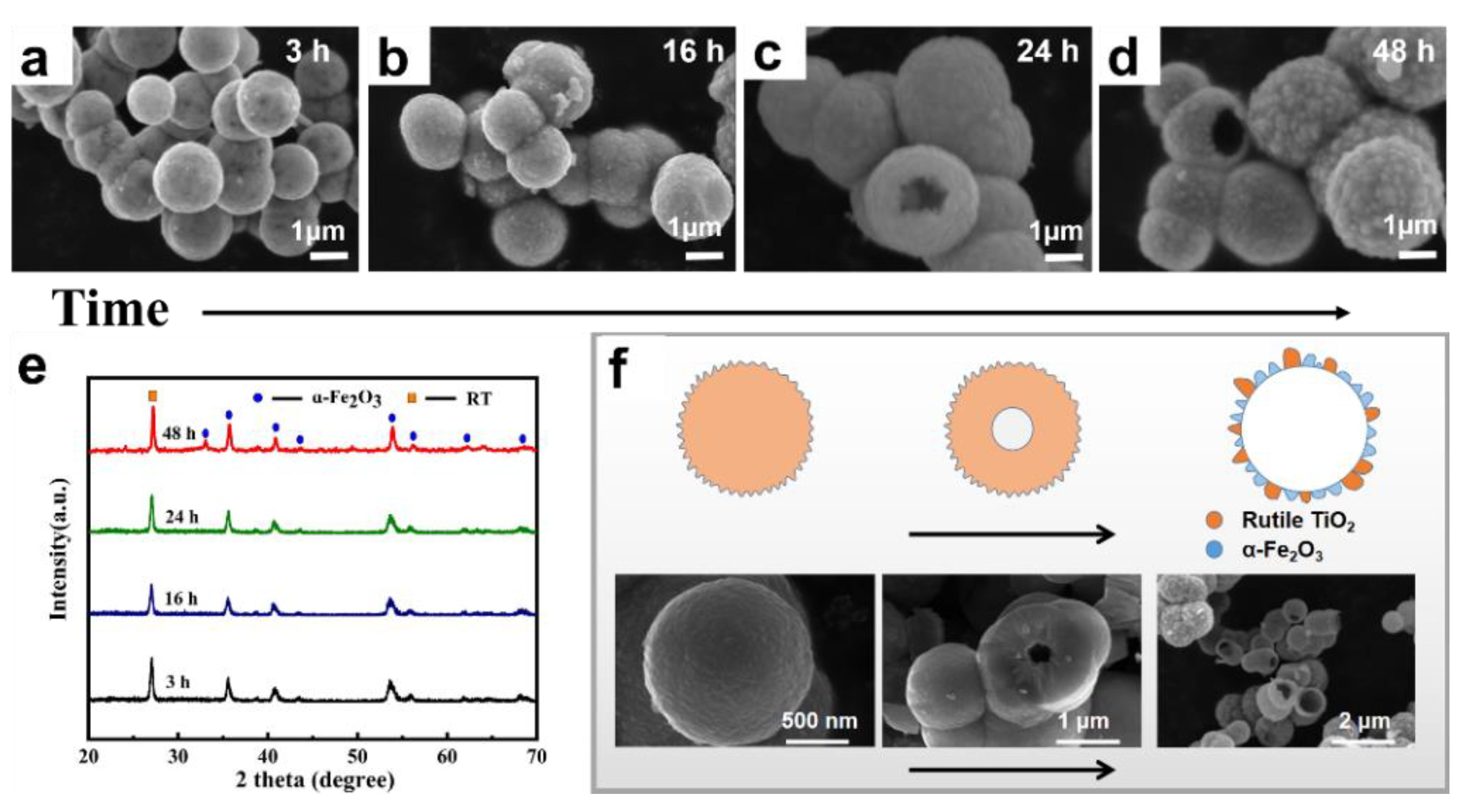
To better understand the formation process of hollow α-Fe2O3/RT microspheres, time-dependent experiments were carried out. As shown in Figure 6, representative SEM images at different time intervals are displayed. When the reaction time was 3 h, the complete regular spherical particles were formed (Figure 6a), and the peaks of α-Fe2O3 and RT could be observed (Figure 6e). The crystallinity of the composite material was the best at 48h. When the reaction time was 16 h, the sample did not change too much, only pyramidal particles of different sizes appeared on the surface, and it was not evident (Figure 6b). However, when the reaction time reached 24 h (Figure 6c) and 48 h (Figure 6d), the spherical hollow sample appeared. The surface of the sample was covered with particles of different sizes. In response to the above experimental results, we proposed the growth mechanism and reaction principle of RT and α-Fe2O3, as shown in Figure 6f. In the beginning, the raw material forms a solid ball under high temperature and pressure. The formed α-Fe2O3/RT nanoparticles are unstable and tend to form hollow structures, which may be due to the minimization of interfacial energy [33]. As the reaction time is prolongs, a hollow structure is found in the center of the solid ball. The hollow structure expands and finally stops on the sphere’s surface, forming a spherical shell, and the surface is loaded with α-Fe2O3 and RT [34,35,36]. The hollow structure’s formation is that small particles gradually adhere to large particles to form a sheet, commonly known as the Ostwald ripening process [37].
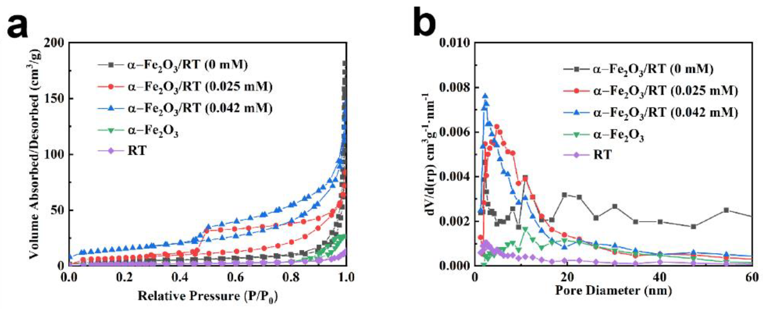
As shown in Figure 7a, α-Fe2O3 and RT showed a type II isotherm, which exhibits a non-porous structure, and the isotherms of α-Fe2O3/RT samples were of the type IV hysteresis loop from 0.5 to 1.0 (P/P0) [15]. The pore distribution of the composite materials was 2–20 nm (Figure 7b), which indicates that the composite materials were mesopore structures [14]. The formation of nanopores may have been due to the accumulation of self-assembled units. The specific surface area of α-Fe2O3/RT (0.025 mM), α-Fe2O3/RT (0.042 mM), α-Fe2O3/RT (0 mM), α-Fe2O3, and RT was 56, 48, 32, 28, and 26 m2/g, respectively.

2.2. Magnetic Properties

Figure 8a,b show the room temperature magnetic hysteresis loops of synthesized α-Fe2O3, RT, and hollow α-Fe2O3/RT structures in a magnetic field sweeping from −15 to 15k Oe and Table S1 (Supplementary Materials) collects the values of remnant magnetization (Mr) and coercivity (Hc). It was inferred from the hysteresis loop that the composite material was paramagnetic [38,39]. The coercivity of the samples, obtained by adding different amounts of H2PO4 anion, increased with the concentration of H2PO4 anions, as shown in Figure 8a,b. The introduction of H2PO4 anions could increase the coercivity by domain wall pinning and/or spin pinning [40]. It has been reported that when the average particle size is larger than 183 nm, the coercivity of α-Fe2O3 increases with the decrease in particle size [41]. In addition to the two above factors, studies show that the appearance of a hollow void could introduce kinks near zero magnetization in the M-H loop due to two vortex states with opposite directions [42]. Therefore, the hollow structures might also have contributed to the smaller coercivity. From this result, we can infer that the composite material can be recycled with magnets to avoid secondary pollution.

2.3. Enhancement of Photocatalytic Activity

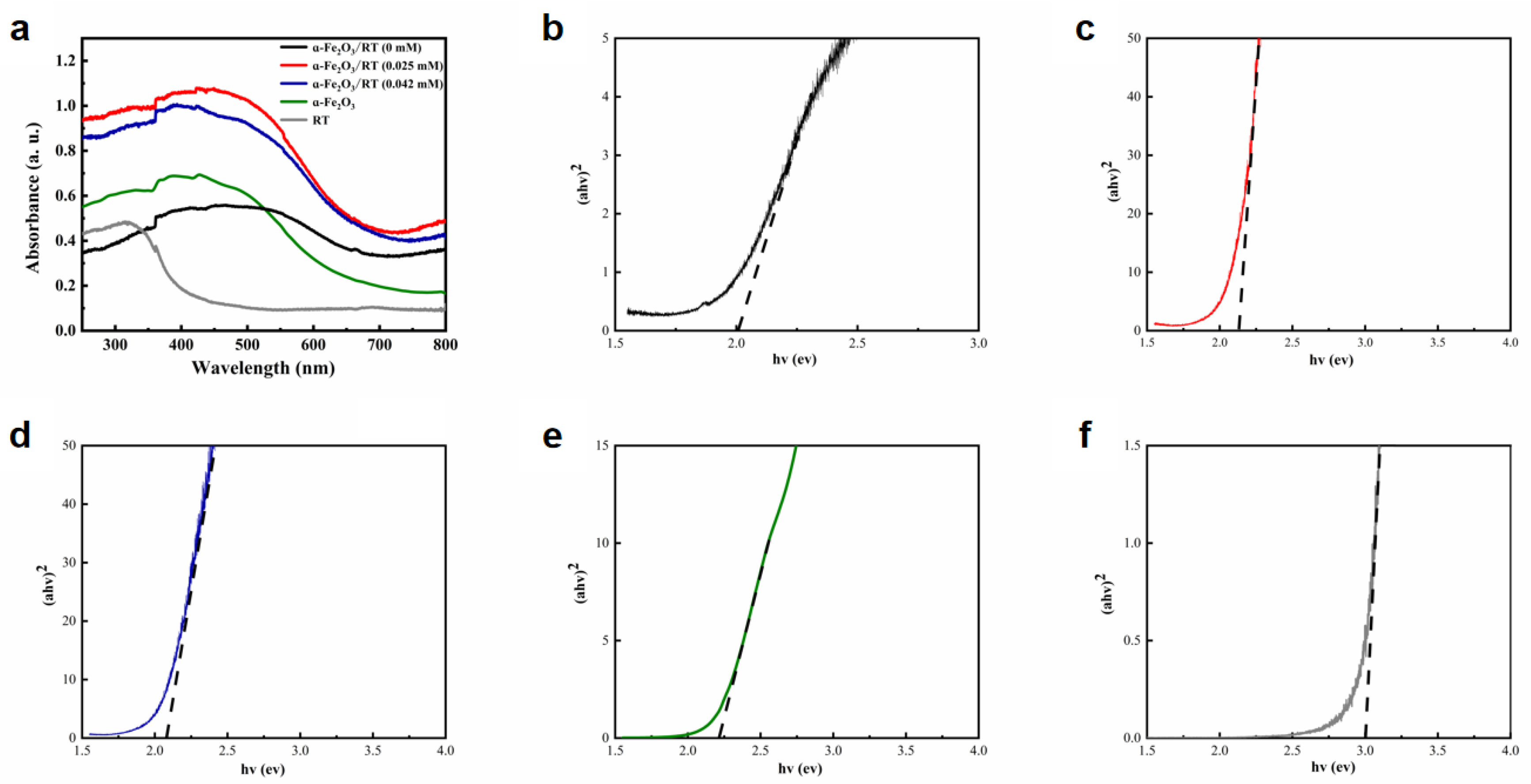
The photocatalytic activity of α-Fe2O3/RT is closely related to its energy band. Figure 9a shows the UV-visible absorption spectra of the α-Fe2O3, RT, and α-Fe2O3/RT hollow spheres wavelength of 250–800 nm. α-Fe2O3/RT (0.025 mM) showed stronger absorption from 400 to 800 nm. As shown in Figure 9b–f, α represents the absorption coefficient (cm−1), hν is the photon energy (eV), A is the equation constant, and Eg is the optical bandgap. The direct optical bandgaps were obtained from the intercept of the linear fitting in the plotted experimental graph of (αhν)2 against the photon energy (hν). The optical bandgaps were found to be 2.00, 2.12, 2.08, 2.20, and 3.00 eV for α-Fe2O3/RT (0 mM), α-Fe2O3/RT (0.025 mM), α-Fe2O3/RT (0.042 mM), α-Fe2O3, and RT samples, respectively. This shows that the combined effect of α-Fe2O3 and RT enhanced its absorption capacity and indicates that the composite material formed a heterojunction and changed the bandwidth. The heterojunction structure facilitated the separation of electron and hole pairs, thereby improving photocatalytic performance.
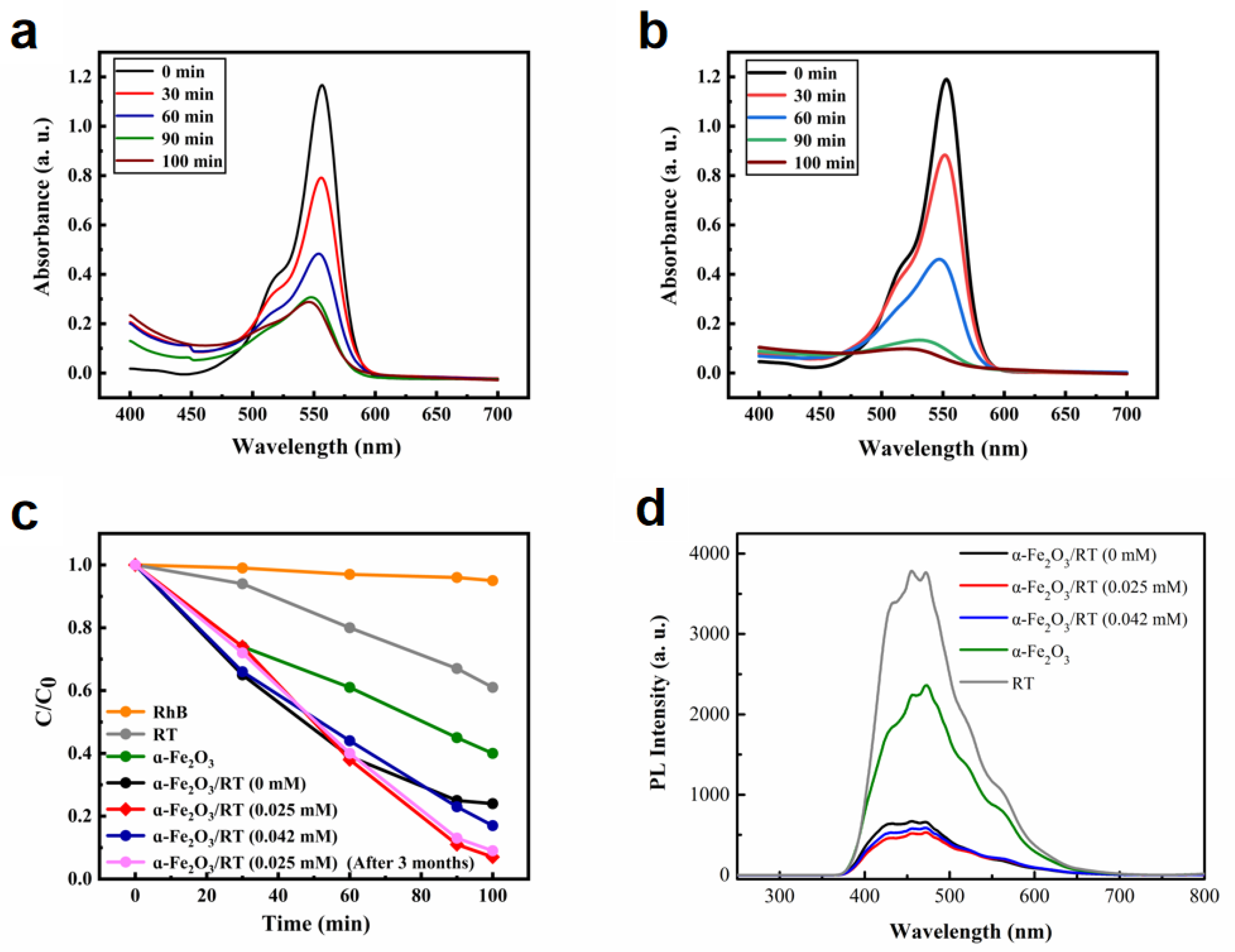
Before the photocatalytic reaction, all samples were subjected to a dark treatment for 30 min for physical adsorption. The catalyst-free pure rhodamine B (RhB) degradation experiment was the reference object. As shown in Figure 10a,b, the absorption peak at 553 nm decreased gradually with increasing irradiation time and almost disappeared after 100 min, indicating that the α-Fe2O3/RT hollow microspheres exhibited excellent photocatalytic activity. In Figure 10c, when the RhB solution was irradiated without a photocatalyst, the degradation rate after 100 min was less than 5%, which was due to the photolysis of the organic dye RhB. For RT, α-Fe2O3, α-Fe2O3/RT (0 mM), α-Fe2O3/RT (0.025 mM), α-Fe2O3/RT (0.042 mM), and α-Fe2O3/RT (0.025 mM) after three months of photocatalysts, the degradation rate of organic dye RhB after 100 min was about 16%, 60%, 76%, 93%, 83%, and 91%, respectively. The α-Fe2O3/RT photocatalyst showed better photocatalytic performance than the α-Fe2O3 and RT photocatalysts, and RT showed extremely little photocatalytic activity under visible light irradiation because it could not be activated by visible light due to its wide energy gap (3.0 eV) [43].
In order to investigate whether charge transfer is possible between α-Fe2O3 and RT, we carried out photoluminescence (PL) measurements, as shown in Figure 10d. Strong emission from pure α-Fe2O3 and RT was observed under 200 nm excitation, but the α-Fe2O3/RT resulted in low emission intensity, and α-Fe2O3/RT (0.025 mM) had the lowest emission intensity. This therefore indicates the efficiency of charge separation and transfer between α-Fe2O3 and RT. The lower recombination rate of electron-hole indeed enhanced the photocatalytic performance. Compared with α-Fe2O3/RT (0 mM) and α-Fe2O3/RT (0.042 mM), α-Fe2O3/RT (0.025 mM) showed better photocatalytic performance. It is likely that the high photocatalytic activity resulted from the hollow structure, large specific surface area, strong absorption of visible light, and low recombination rate of the electron hole [44,45]. α-Fe2O3/RT (0.025 mM) showed a larger specific surface area (56 m2/g) than α-Fe2O3/RT (0 mM) and α-Fe2O3/RT (0.042 mM). A larger specific surface area provides more active sites for photocatalytic reactions. Therefore, the photo-generated charge carriers could more easily transfer to the surface to degrade the adsorbed organic dyes. In contrast, we also compared the photocatalytic performance with other work. As shown in Table S2, after being compounded with α-Fe2O3, the photodegradation activity of α-Fe2O3/RT improved, which further demonstrates that α-Fe2O3/RT hollow microspheres could be a promising material for degrading organic dyes. An SEM image of the α-Fe2O3/rutile TiO2 (0.025 mM) after placement for three months is shown in Figure S1. The morphology and structure of α-Fe2O3/rutile TiO2 (0.025 mM) showed almost no change, which was very important for maintaining the samples’ photocatalytic activity.
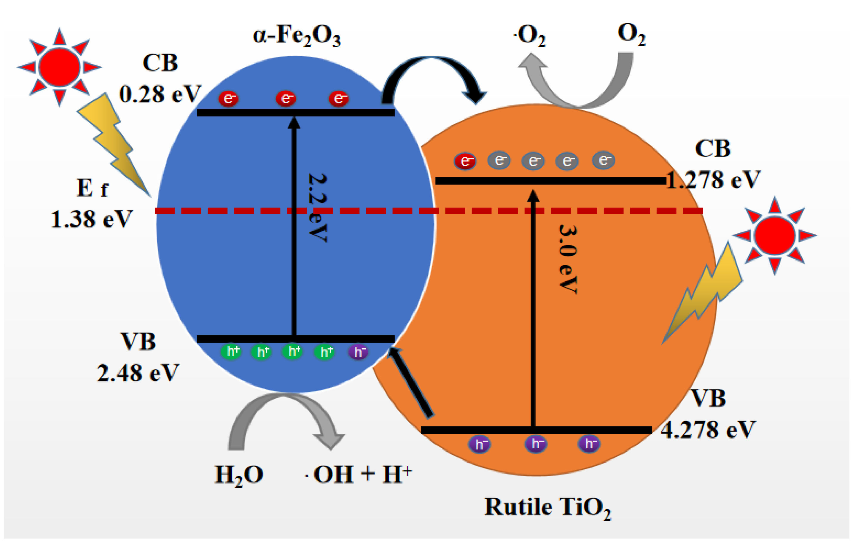
Furthermore, the schematic diagrams of the photocatalytic mechanism of α-Fe2O3/RT under UV and visible light irradiation are shown in Figure 11. After contact, the two semiconductors could reach the same Fermi level because of the different work functions of the α-Fe2O3 (5.88 eV) and TiO2 (4.308 eV) [20]; the photoelectrons of α-Fe2O3 could go through the barrier and transfer to the CB (conduction band) of TiO2 due to the CB of TiO2 being lower than that of the α-Fe2O3 [46,47]. These electrons were captured by dissolved oxygen in an aqueous solution to produce the reactive oxygen species (·O2). On the contrary, the remaining holes of TiO2 in the VB (valence band) would rapidly transfer to the VB of α-Fe2O3. H2O traps the holes to form hydroxyl radicals (·OH). These reactive oxygen species (·O2) and hydroxyl radicals (·OH) with high activities can degrade RhB rapidly [48,49,50]. Therefore, in this wide-narrow band gap composited photocatalysis system, the photogenerated electron-hole pairs are separated at the contact surfaces efficiently and increase the lifetime of the charge carriers [51,52]. The effective separation of the electron-hole pair is the final reason for the improvement of photocatalytic abilities.

3. Materials and Methods

3.1. Materials and Techniques

Ferric chloride (FeCl3·6H2O, ≥99.0%), sodium dihydrogen phosphate (NaH2PO4, ≥99.0%), and sodium fluoride (NaF, ≥98.0%) were purchased from Sinopharm Chemical Reagent Co., Ltd. (Ningbo, China). Ammonium fluorotitanate ((NH4)2TiF6, ≥98.0%) was purchased from Tianjin Guangfu Fine Chemical Research Institute. Deionized water was used throughout the experiment. Tetrabutyl titanate and ethanol were purchased from Tianjin Yongda Chemical Reagent Co., Ltd, Tianjin, China.
The materials were characterized by X-ray diffraction (XRD) with an MSXD-3 X-ray diffractometer using Cu-Kα radiation (α = 0.15418 nm), and an accelerating voltage of 40 kV and an emission current of 40 mA were employed. Transmission electron microscopy (TEM) observation was carried out on a Tecnai G2 F20 S-TWIN (FEI) instrument operated at 200 kV accelerating voltage. Scanning electron microscopy (SEM) observation was carried out on a Quanta 250 (FEI) operated at an accelerating voltage of 30 kV.
N2 adsorption/desorption isotherms were obtained on a Micromeritics ASAP Tristar II 3020 apparatus. The pore size distribution curves were calculated from the adsorption branch of the N2 isotherm through the Barrett–Joyner–Halenda (BJH) method.
The photocatalyst was exposed to a 300 W xenon lamp (HSX-F/UV 300, Beijing NBeT), using the visible spectrum (390–770 nm) and the intensity was 1900 mW/cm2.
The photoluminescence measurement was measured by fluorescence spectrometer ((F-4600, Hitachi) at 200 nm.
The magnetic properties of the as-synthesized samples were measured with a physical property measurement system (PPMS-9T, EverCoolII, USA).

3.2. Synthesis of the Rutile TiO2 (RT)

Tetrabutyl titanate was added to the 2 mol/L HCl solution, with the temperature maintained below 10 °C by an ice-water bath. The mixture was heated in a water bath at 80 °C for 4 h to produce a white suspension. Then the suspension was placed in a hydrothermal reactor and heated at 160 °C for 6 h. It was washed five times with deionized water. After drying at 80 °C in air, RT was obtained.

3.3. Synthesis of the α-Fe2O3

FeCl3·6H2O (0.75 g, 2.7 mM), NaF (0.126 g, 3 mM), and NaH2PO4 (0.003 g, 0.025 mM) were added to 60 mL of deionized water. After sonication for 30 min, the solution was transferred to a Polytetrafluoroethylene (PTFE)-lined stainless-steel autoclave with a capacity of 70 mL and kept at 220 °C for 48 h. The sample was washed 5 times with deionized water and ethanol. After drying in a vacuum oven at 80 °C for 10 h, the final samples were obtained.

3.4. Synthesis of Hollow α-Fe2O3/RT Nanospheres

FeCl3·6H2O (0.75 g, 2.7 mM), (NH4)2TiF6 (0.55 g, 2.8 mM), NaF (0.126 g, 3 mM), and NaH2PO4 (0.003 g, 0.025 mM) were added to 60 mL of deionized water. After sonication for 30 min, the solution was transferred to a PTFE-lined stainless-steel autoclave with a capacity of 70 mL and kept at 220 °C for 48 h. The sample was washed 5 times with deionized water and ethanol. After drying in a vacuum oven at 80 °C for 10 h, the final samples were obtained.

3.5. Photocatalytic Reaction

The experimental conditions were as follows: The photocatalytic reaction system consisted of a 300W Xenon lamp equipped with a UV filter and placed above the RhB solution with a distance of about 10 cm, which was mounted with a 400 nm cut-off glass filter. A total of 20.0 mg of α-Fe2O3/RT photocatalyst and 50.0 mL of RhB dye aqueous solution (30.0 mg/L) were mixed in a Pyrex reactor and stirred in the dark for 30 min. After that, the mixed solution was exposed to a 300W xenon lamp while stirring. Subsequently, 3.0 mL of the suspension were centrifuged at 10,000 rpm for 15 min to remove the photocatalyst. Finally, by monitoring the absorbance at 553 nm, the concentration of RhB was monitored with a TU-1901 ultraviolet-visible spectrophotometer.

4. Conclusions

A self-assembled paramagnetic α-Fe2O3/RT hollow sphere composite structure with controllable morphology was successfully synthesized via a template-free hydrothermal method. The α-Fe2O3/RT hollow sphere assembled by nanoparticles and nanocubes had good crystallinity and a large specific surface area. The self-assembled structure provided more exposed active sites and improved the light absorbance. A time-dependent experiment confirmed the hollow structure formed by the Ostwald ripening process. Phosphate played a significant role in forming α-Fe2O3/RT hollow spheres, and the hollow structure was beneficial to improving the photocatalytic performance. We believe that the formation of a heterojunction between α-Fe2O3 and RT promoted photogenerated electrons and holes, which helped prolong the carrying time and then encourage charge separation. Therefore, the degradation rate of RhB with α-Fe2O3/RT (0.025 mM) was up to 93% after 100 min. In addition, the synthesized samples showed paramagnetism and could be easily recycled. After compounding, the α-Fe2O3/RT composite material had a visible light response and has potential application prospects in the photocatalytic degradation of organic dyes.

Supplementary Materials

The following are available online at https://www.mdpi.com/2073-4344/11/3/396/s1, Figure S1: SEM image of α-Fe2O3/rutile TiO2 (0.025 mM) placed after 3 months. The morphology and structure of the as-synthesized sample has almost no change. Figure S2. Image of magnet adsorbing α-Fe2O3/rutile TiO2 (0.025 mM). Table S1: The values of remnant magnetization (Mr) and coercivity (Hc) of the samples. Table S2: Comparison of the photocatalytic performances of other materials.

Author Contributions

Z.Z. designed the work, performed material synthesis and characterization, and wrote the final draft; H.Y. contributed to the work, editing of the draft, and the writing; Y.L. contributed to the material synthesis; Y.Z. and J.Z. contributed to the review; J.Y. contributed to the work; J.T. and F.W. contributed to the supervision, funding acquisition, review, and editing of the draft. All authors have read and agreed to the published version of the manuscript.

Funding

This research was funded by the Shandong Provincial Natural Science Foundation, China (ZR2018JL021) and the Key Research and Development Program of Shandong Province (2019GGX102067).

Data Availability Statement

The raw/processed data required to reproduce these findings cannot be shared at this time as the data also forms part of an ongoing study.

Conflicts of Interest

The authors declare no conflict of interest.

References

  1. Asaithambi, S.; Sakthivel, P.; Karuppaiah, M. Influence of Ni Doping in SnO2 Nanoparticles with Enhanced Visible Light Photocatalytic Activity for Degradation of Methylene Blue Dye. J. Nanosci. Nanotechnol. 2019, 19, 4438–4446. [Google Scholar] [CrossRef]
  2. Idrus-Saidi, S.; Tang, J.; Ghasemian, M.; Yang, J.; Han, J.-L.; Syed, N.; Daeneke, T.; Abbasi, R.; Koshy, P.; O′Mullane, A.; et al. Liquid metal core-shell structures functionalised via mechanical agitation: The example of Field′s metal. J. Mater. Chem. A 2019, 7, 17876. [Google Scholar] [CrossRef]
  3. Kment, S.; Riboni, F.; Pausova, S.; Wang, L.; Han, H. Photoanodes based on TiO2 and α-Fe2O3 for solar water splitting-the superior role of 1D nanoarchitecture and combined heterostructures. Chem. Soc. Rev. 2017, 46, 3716–3769. [Google Scholar] [CrossRef]
  4. Ghasemian, M.; Mayyas, M.; Idrus-Saidi, S.; Jamal, M.; Yang, J.; Daeneke, T.; Kalantar-Zadeh, K. Self-Limiting Galvanic Growth of MnO2 Mnolayers on a Liquid Metal-Appled to Photocatalysis. Adv. Funct. Mater. 2019, 29, 1901649. [Google Scholar] [CrossRef]
  5. Wang, F.Y.; Yang, Q.D.; Xu, G.; Lei, N.Y.; Ho, J.C. Highly active and enhanced photocatalytic silicon nanowire arrays. Nanoscale 2011, 3, 3269. [Google Scholar] [CrossRef]
  6. Zhang, Z.Q.; Bai, L.L.; Li, Z.J. Review of strategies for the fabrication of heterojunctional nanocomposites as efficient visible-light catalysts by modulating excited electrons with appropriate thermodynamic energy. J. Mater. Chem. A 2019, 7, 10879. [Google Scholar] [CrossRef]
  7. Gao, C.M.; Wei, T.; Zhang, Y.Y.; Song, X.H.; Huan, Y.; Liu, H.; Chen, X.D. A Photoresponsive Rutile TiO2 Heterojunction with Enhanced Electron-Hole Separation for High-Performance Hydrogen Evolution. Adv. Mater. 2019, 31, 1806596. [Google Scholar] [CrossRef] [PubMed]
  8. Yang, Y.Q.; Liu, G.; Cheng, H.M. Enhanced Photocatalytic H2 Production in Core-Shell Engineered Rutile TiO2. Adv. Mater. 2016, 28, 1600495. [Google Scholar] [CrossRef] [PubMed] [Green Version]
  9. Luan, P.; Xie, M.; Liu, D.N. Effective charge separation in the rutile TiO2 nanorod-coupled α-Fe2O3 with exceptionally high visible activities. Sci. Rep. 2014, 4, 6180. [Google Scholar] [CrossRef] [PubMed]
  10. Sun, J.; Gao, L.; Zhang, Q. Synthesizing and Comparing the Photocatalytic Properties of High Surface Area Rutile and Anatase Titania Nanoparticles. J. Am. Ceram. Soc. 2003, 86, 1677–1682. [Google Scholar] [CrossRef]
  11. Ohno, T.; Furukawa, K.; Matsumura, M. Photocatalytic Activities of Pure Rutile Particles Isolated from TiO2 Powder by Dissolving the Anatase Component in HF Solution. J. Phys. Chem. B 2001, 105, 2417–2420. [Google Scholar] [CrossRef]
  12. Naya, S.; Nikawa, T.; Kimura, K.; Tada, H. Rapid and Complete Removal of Nonylphenol by Gold Nanoparticle/Rutile Titanium (IV) Oxide Plasmon Photocatalyst. ACS Catal. 2015, 3, 10–13. [Google Scholar] [CrossRef]
  13. Xia, C.X.; Wang, H.; Kim, J.K.; Wang, J.Y. Rational Design of Metal Oxide-Based Heterostructure for Efficient Photocatalytic and Photoelectrochemical Systems. Adv. Funct. Mater. 2020, 2008247. [Google Scholar] [CrossRef]
  14. Xu, H.F.; Li, G.; Zhu, G.; Zhu, K.-R.; Jin, S.-W. Enhanced photocatalytic degradation of rutile/anatase TiO2 heterojunction nanoflowers. Catal. Commun. 2015, 62, 52–56. [Google Scholar] [CrossRef]
  15. Ghosh, M.; Liu, J.W.; Steven, S.; Chuang, C.; Jana, S.-C. Fabrication of Hierarchical V2O5 Nanorods on TiO2 Nanofibers and Their Enhanced Photocatalytic Activity under Visible Light. ChemCatChem 2018, 10, 3305. [Google Scholar] [CrossRef]
  16. Zhang, R.-N.; Sun, M.-L.; Zhao, G.-D.; Yin, G.-C.; Liu, B. Hierarchical Fe2O3 nanorods/TiO2 nanosheets heterostructure: Growth mechanism, enhanced visible-light photocatalytic and photoelectrochemical performances. Appl. Surf. Sci. 2019, 475, 380–388. [Google Scholar] [CrossRef]
  17. Kevin, S.; Radek, Z.; Florian, L.F.; Rosa, R. Photoelectrochemical Water Splitting with Mesoporous Hematite Prepared by a Solution-Based Colloidal Approach. J. Am. Chem. Soc. 2010, 132, 7436–7444. [Google Scholar]
  18. Tao, Q.Q.; Huang, X.; Bi, J.T.; Yu, L.; Hao, H.X. Aerobic Oil-Phase Cyclic Magnetic Adsorption to Synthesize 1D Fe2O3@TiO2 Nanotube Composites for Enhanced Visible-Light Photocatalytic Degradation. Nanomaterials 2020, 10, 1345. [Google Scholar] [CrossRef] [PubMed]
  19. Wang, T.; Yang, G.D.; Liu, J.; Yang, B.L. Orthogonal synthesis, structural characteristics, and enhanced visible-light photocatalysis of mesoporous Fe2O3/TiO2 heterostructured microspheres. Appl. Surf. Sci. 2014, 311, 314–323. [Google Scholar] [CrossRef]
  20. Liu, J.; Yang, S.L.; Wu, W.; Tian, Q.Y.; Cui, S.Y.; Dai, Z.G.; Ren, F. 3D Flowerlike α-Fe2O3 @TiO2 Core-Shell Nanostructures: General Synthesis and Enhanced Photocatalytic Performance. ACS Sustain. Chem. Eng. 2015, 3, 2975–2984. [Google Scholar] [CrossRef]
  21. Xie, M.Z.; Meng, Q.Q.; Luan, P.; Feng, Y.-J. Synthesis of mesoporous TiO2-coupled Fe2O3 as efficient visible nano-photocatalysts for degrading colorless pollutants. RSC Adv. 2014, 4, 520–527. [Google Scholar] [CrossRef]
  22. Wang, Z.Y.; Zhou, L.; Lou, X.-W. Metal Oxide Hollow Nanostructures for Lithium on Batteries. Adv. Mater. 2012, 24, 1903–1911. [Google Scholar] [CrossRef] [PubMed]
  23. Yang, G.D.; Yang, B.L.; Xiao, T.C.; Yan, Z.F. One-step solvothermal synthesis of hierarchically porous nanostructured CdS/TiO2 heterojunction with higher visible light photocatalytic activity. Appl. Surf. Sci. 2013, 283, 402–410. [Google Scholar] [CrossRef]
  24. Xiang, L.Q.; Zhao, X.P.; Yin, J.B.; Fan, B.L. Well-organized 3D urchin-like hierarchical TiO2 microspheres with high photocatalytic activity. J. Mater. Sci. 2012, 47, 1436–1445. [Google Scholar] [CrossRef]
  25. Gao, P.; Sun, D.D. Ultrasonic Preparation of Hierarchical Graphene-Oxide/TiO2 Composite Microspheres for Efficient Photocatalytic Hydrogen Production Chem. Asian J. 2013, 8, 2779–2786. [Google Scholar] [CrossRef]
  26. Xiang, Q.J.; Yu, J.G.; Cheng, B.; Ong, H.C. Microwave-Hydrothermal Preparation and Visible-Light Photoactivity of Plasmonic Photocatalyst Ag-TiO2 Nanocomposite Hollow Spheres. Chem. Asian J. 2010, 5, 1466–1474. [Google Scholar] [CrossRef] [PubMed]
  27. Andersson, M.; Kiselev, A.; Osterlund, L. Microemulsion-mediated room-temperature synthesis of high-surface-area rutile and its photocatalytic performance. J. Phys. Chem. C 2007, 111, 6789–6797. [Google Scholar] [CrossRef]
  28. Murray, J.; Kirwan, L.; Loan, M.; Hodnett, B.-K. In-situ synchrotron diffraction study of the hydrothermal transformation of goethite to hematite in sodium aluminate solutions. Hydrometallurgy 2009, 95, 239–246. [Google Scholar] [CrossRef]
  29. Wu, Y.; Zhang, W.; Yu, W.; Liu, H.; Chen, R.; Wei, Y. Ferrihydrite preparation and its application for removal of anionic dyes. Front. Environ. Sci. Eng. 2015, 9, 411–418. [Google Scholar] [CrossRef]
  30. Žic, M.; Ristić, M.; Musić, S. Effect of phosphate on the morphology and size of α-Fe2O3 particles crystallized from dense β-FeOOH suspensions. J. Alloys Compd. 2008, 466, 498–506. [Google Scholar] [CrossRef]
  31. Žic, M.; Ristić, M.; Musić, S. Precipitation of α-Fe2O3 from dense β-FeOOH suspensions with added ammonium amidosulfonate. J. Mol. Struct. 2009, 924–926, 235–242. [Google Scholar] [CrossRef]
  32. Qi, Z.; Liang, H.; Wei, C.; Wang, Z.; Wang, R. X-shaped hollow α-FeOOH penetration twins and their conversion to α-Fe2O3 nanocrystals bound byhigh-index facets with enhanced photocatalytic activity. Chem. Eng. J. 2015, 274, 224–230. [Google Scholar]
  33. Zhu, L.P.; Wang, L.L.; Bing, N.C.; Huang, C.; Wang, L.J.; Liao, G.H. Porous flfluorine-doped γ-Fe2O3 hollow spheres: Synthesis, growth mechanism, and their application in photocatalysis. ACS Appl. Mater. Interfaces 2013, 5, 12478–12487. [Google Scholar] [CrossRef]
  34. Lou, X.W.; Wang, Y.; Yuan, C.; Lee, J.Y.; Archer, L.A. Template-free synthesis of SnO2 hollow nanostructures with high lithium storage capacity. Adv. Mater. 2006, 18, 2325–2329. [Google Scholar] [CrossRef]
  35. Zhu, L.P.; Xiao, H.M.; Zhang, W.-D.; Yang, G.; Fu, S.-Y. One-pot template-free synthesis of monodisperse and single-crystal magnetite hollow spheres by a simple solvothermal route. Cryst. Growth Des. 2008, 8, 957–963. [Google Scholar] [CrossRef]
  36. Yu, J.; Yu, X.; Huang, B.; Zhang, X.; Dai, Y. Hydrothermal synthesis and visible-light photocatalytic activity of novel cage-like ferric oxide hollow spheres. Cryst. Growth Des. 2009, 9, 1474–1480. [Google Scholar] [CrossRef]
  37. Niu, K.Y.; Park, J.; Zheng, H.M.; Alivisatos, A.P. Revealing Bismuth Oxide Hollow Nanoparticle Formation by the Kirkendall Effffect. Nano Lett. 2013, 13, 5715–5719. [Google Scholar] [CrossRef] [Green Version]
  38. Liang, H.; Chen, W.; Jiang, X.; Xu, X.; Xu, B.; Wang, Z. Synthesis of 2D hollow hematite microplatelets with tuneable porosity and their comparative photocatalytic activities. J. Mater. Chem. A 2014, 2, 4340–4346. [Google Scholar] [CrossRef]
  39. Yin, H.; Zhao, Y.L.; Hua, Q.S.; Zhang, J.M.; Zhang, Y.S.; Yuan, J.S. Controlled Synthesis of Hollow α-Fe2O3 Microspheres Assembled With Ionic Liquid for Enhanced Visible-Light Photocatalytic Activity. Front. Chem. 2019, 10, 3389. [Google Scholar] [CrossRef] [PubMed]
  40. Lv, B.L.; Xu, Y.; Gao, Q.; Wu, D.; Sun, Y.-H. Controllable synthesis and magnetism of iron oxides nanorings. J. Nanosci. Nanotechnol. 2010, 10, 2348–2359. [Google Scholar] [CrossRef] [PubMed]
  41. Lv, B.L.; Liu, Z.Y.; Tian, H.; Xu, Y.; Wu, D.; Sun, Y.H. Single-Crystalline Dodecahedral and Octodecahedral α-Fe2O3 Particles Synthesized by a Fluoride Anion-Assisted Hydrothermal Method. Adv. Funct. Mater. 2010, 20, 3987–3996. [Google Scholar] [CrossRef]
  42. Li, Z.; Cai, W.; Duan, G.; Liu, P. Magnetic step regions in α-Fe2O3 nanostructured ring arrays. Phys. E 2008, 40, 680–683. [Google Scholar] [CrossRef]
  43. Fang, J.; Shi, F.; Bu, J.; Ding, J.; Xu, S.; Bao, J. One-Step Synthesis of Bifunctional TiO2 Catalysts and Their Photocatalytic Activity. J. Phys. Chem. C 2010, 114, 7940–7948. [Google Scholar] [CrossRef]
  44. Wu, W.; Xiao, X.; Zhang, S.; Ren, F.; Jiang, C. Facile Method to Synthesize Magnetic Iron Oxides/TiO2 Hybrid Nanoparticles and Their Photodegradation Application of Methylene Blue. Nanoscale Res. Lett. 2011, 6, 533. [Google Scholar] [CrossRef] [Green Version]
  45. Palanisamy, B.; Babu, C.; Sundaravel, B.; Anandan, S.; Murugesan, V. Sol-Gel Synthesis of Mesoporous Mixed Fe2O3/TiO2 Photocatalyst: Application for Degradation of 4-chlorophenol. J. Hazard. Mater. 2013, 252–253, 233–242. [Google Scholar] [CrossRef]
  46. Peng, L.; Xie, T.; Lu, Y.; Fan, H.; Wang, D. Synthesis, Photoelectric Properties and Photocatalytic Activity of the Fe2O3/TiO2 Heterogeneous Photocatalysts. Phys. Chem. Chem. Phys. 2010, 12, 8033–8041. [Google Scholar] [CrossRef] [PubMed]
  47. Niu, M.; Huang, F.; Cui, L.; Huang, P.; Yu, Y.; Wang, Y. Hydrothermal Synthesis, Structural Characteristics, and Enhanced Photocatalysis of SnO2/α-Fe2O3 Semiconductor Nanoheterostructures. ACS Nano 2010, 4, 681–688. [Google Scholar] [CrossRef] [PubMed]
  48. Sridharan, K.; Jang, E.; Park, T.J. Novel visible light active graphitic C3N4-TiO2 composite photocatalyst: Synergistic synthesis, growth and photocatalytic treatment of hazardous pollutants. Appl. Catal. B 2013, 142, 718–728. [Google Scholar] [CrossRef]
  49. Mrowetz, M.; Balcerski, W.; Colussi, A.J.; Hoffmann, M.R. Oxidative Power of Nitrogen-Doped TiO2 Photocatalysts under Visible Illumination. J. Phys. Chem. B 2004, 108, 17269–17273. [Google Scholar] [CrossRef]
  50. Xue, C.; Wang, T.; Yang, G.; Yang, B.; Ding, S. A facile strategy for the synthesis of hierarchical TiO2/CdS hollow sphere heterostructures with excellent visible light activity. J. Mater. Chem. A 2014, 2, 7674–7679. [Google Scholar] [CrossRef]
  51. Qu, Y.; Duan, X. Progress, challenge and perspective of heterogeneous photocatalysts. Chem. Soc. Rev. 2013, 14, 2568–2580. [Google Scholar] [CrossRef] [PubMed]
  52. Ji, T.; Ha, E.; Wu, M.Z.; Hu, X.; Wang, J.; Sun, Y.G.; Li, S.J.; Hu, J.Q. Controllable Hydrothermal Synthesis and Photocatalytic Performance of Bi2MoO6 Nano/Microstructures. Catalysts 2020, 10, 1161. [Google Scholar] [CrossRef]
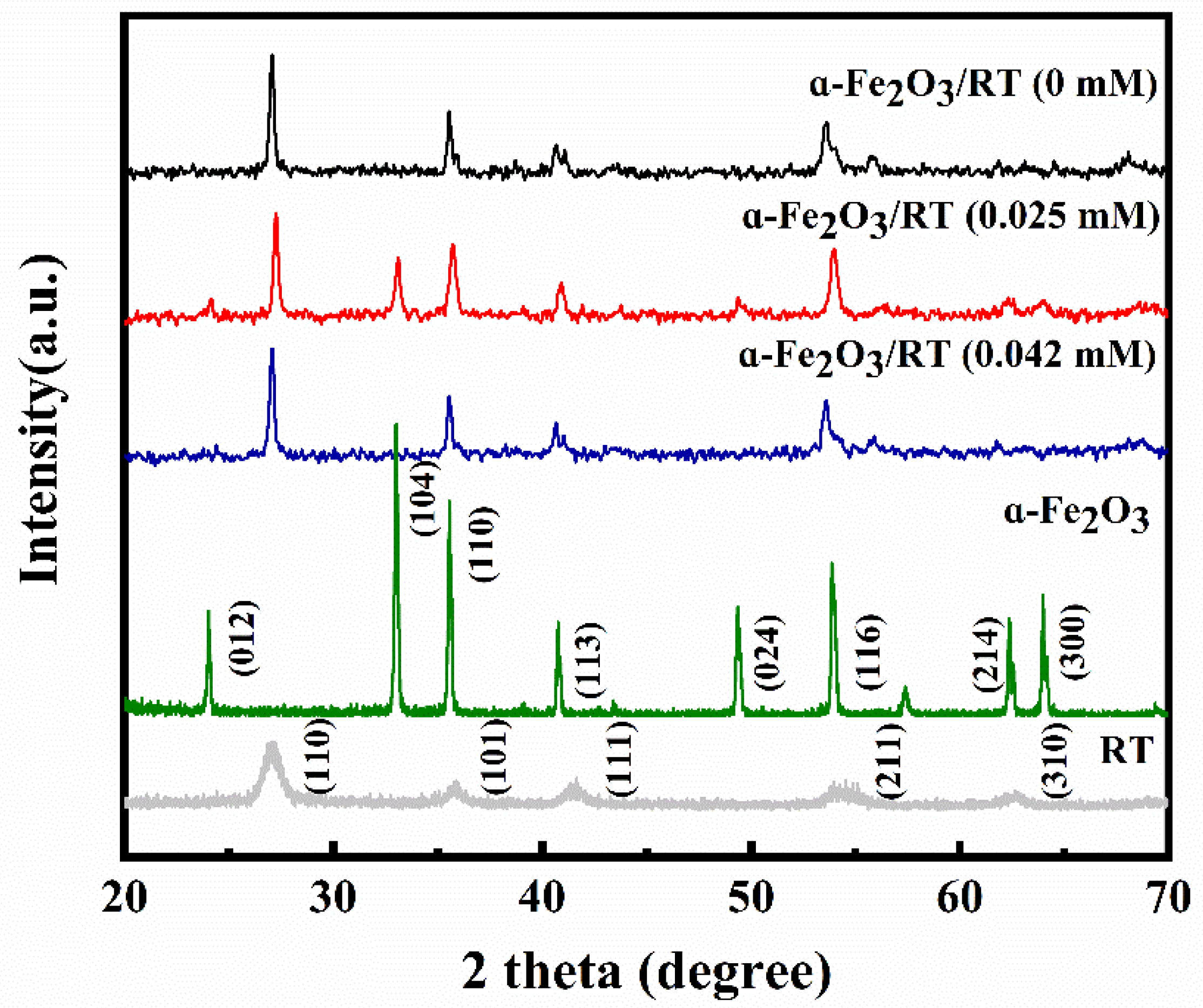
Figure 1. XRD patterns of α-Fe2O3/RT with phosphate addition of 0 mM, 0.025 mM, and 0.042 mM; α-Fe2O3 and RT.
Catalysts 11 00396 g001
Figure 2. (a) SEM of RT and (b) histogram of the particle size distribution; (c) SEM of α-Fe2O3 and (d) histogram of the particle size distribution.
Catalysts 11 00396 g002
Figure 3. SEM of α-Fe2O3/RT prepared with varying additions of phosphate: (ac) 0 mM, (df) 0.025 mM, and (gi) 0.042 mM.
Catalysts 11 00396 g003
Figure 4. (ad) Ti, Fe, and O elemental mapping.
Catalysts 11 00396 g004
Figure 5. (ac) Low and high magnification TEM images and (d) HRTEM image of α-Fe2O3/RT (0.025 mM).
Catalysts 11 00396 g005
Figure 6. (ad) SEM images of hollow α-Fe2O3/RT (0.025 mM), (e) XRD patterns of hollow α- Fe2O3/RT (0.025 mM), and (f) schematic illustration of the formation of hollow α-Fe2O3/RT nanospheres.
Catalysts 11 00396 g006
Figure 7. (a) N2 adsorption/desorption isotherm, (b) the corresponding pore size distribution of the α-Fe2O3/RT (0 mM), α-Fe2O3/RT (0.025 mM), α-Fe2O3/RT (0.042 mM), α-Fe2O3, and RT.
Catalysts 11 00396 g007
Figure 8. (a) Room temperature magnetization loops for the as-obtained samples: α-Fe2O3/RT (0 mM), α-Fe2O3/RT (0.025 mM), α-Fe2O3/RT (0.042 mM), α-Fe2O3, and RT and (b) enlarged view of magnetization loops.
Catalysts 11 00396 g008
Figure 9. (a) UV-vis diffuse reflectance spectra and plots of (αhv)2 vs. photon energy hv for samples of (b) α-Fe2O3/RT (0 mM), (c) α-Fe2O3/RT (0.025 mM), (d) α-Fe2O3/RT (0.042 mM), (e) α-Fe2O3, and (f) RT.
Catalysts 11 00396 g009
Figure 10. (a) Absorption spectra of the RhB solution containing α-Fe2O3/RT (0 mM), (b) absorption spectra of the RhB solution containing α-Fe2O3/RT (0.025 mM), and (c) photodegradation process of different catalysts towards RhB under visible light irradiation. (d) PL spectra for α-Fe2O3, RT, and α-Fe2O3/RT samples (0 mM, 0.025 mM, and 0.042 mM, respectively) measured at 200 nm.
Catalysts 11 00396 g010
Figure 11. Schematic diagrams of the photocatalytic mechanism of α-Fe2O3/RT.
Catalysts 11 00396 g011
Publisher’s Note: MDPI stays neutral with regard to jurisdictional claims in published maps and institutional affiliations.