Review

TiO2-Graphene Quantum Dots Nanocomposites for Photocatalysis in Energy and Biomedical Applications

by
Anuja Bokare
,
Sowbaranigha Chinnusamy
and
Folarin Erogbogbo
*
Department of Biomedical Engineering, San Jose State University, 1 Washington Square, San Jose, CA 95112, USA
*
Author to whom correspondence should be addressed.
Catalysts 2021, 11(3), 319; https://doi.org/10.3390/catal11030319
Submission received: 12 January 2021 / Revised: 21 February 2021 / Accepted: 22 February 2021 / Published: 28 February 2021
(This article belongs to the Special Issue Recent Advances in TiO2 Photocatalysts)

Abstract

:
The focus of current research in material science has shifted from “less efficient” single-component nanomaterials to the superior-performance, next-generation, multifunctional nanocomposites. TiO2 is a widely used benchmark photocatalyst with unique physicochemical properties. However, the large bandgap and massive recombination of photogenerated charge carriers limit its overall photocatalytic efficiency. When TiO2 nanoparticles are modified with graphene quantum dots (GQDs), some significant improvements can be achieved in terms of (i) broadening the light absorption wavelengths, (ii) design of active reaction sites, and (iii) control of the electron-hole (e-h+) recombination. Accordingly, TiO2-GQDs nanocomposites exhibit promising multifunctionalities in a wide range of fields including, but not limited to, energy, biomedical aids, electronics, and flexible wearable sensors. This review presents some important aspects of TiO2-GQDs nanocomposites as photocatalysts in energy and biomedical applications. These include: (1) structural formulations and synthesis methods of TiO2-GQDs nanocomposites; (2) discourse about the mechanism behind the overall higher photoactivities of these nanocomposites; (3) various characterization techniques which can be used to judge the photocatalytic performance of these nanocomposites, and (4) the application of these nanocomposites in biomedical and energy conversion devices. Although some objectives have been achieved, new challenges still exist and hinder the widespread application of these nanocomposites. These challenges are briefly discussed in the Future Scope section of this review.

1. Introduction

Smart and multifunctional materials are rapidly transforming the energy and biomedical fields [1,2,3]. The ability to combine atoms, molecules, structures, and processes in new and exciting ways has led to materials that possess advantageous combinations of physicochemical, biological, optical, electrical, and mechanical properties [4,5,6]. Multifunctional materials “activated” by light (photocatalysts) show promise for use in renewable energy technologies, H2 generation, solar cell battery systems, and environmental remediation [7,8]. In addition, these materials can also be designed to provide new functions associated with antibacterial activity, self-cleaning, self-healing, super-hard, and solar reflectivity for desired end-use applications [9,10,11,12]. Some of the applications of multifunctional materials in revolutionizing energy and biomedical research are shown in Figure 1 [13].
The promise of multifunctional materials for catalysis is vast; however, integrating different properties and functions into a single-material system is a fundamental challenge that needs to be repeatedly overcome for the advancement of photocatalysis [10,14,15]. For example, titania (TiO2) is one of the most widely used photocatalysts in the field of environmental applications due to its wide bandgap, photochemical stability, nontoxic nature, and low cost [16,17]. However, the inherent optical and electronic properties of TiO2 are insufficient to achieve adequate catalytic efficiency for energy harvesting and contaminant removal [18]. The insufficient catalytic efficiency of TiO2 is attributed to (1) its very limited capability to use solar energy and (2) the rapid recombination of its photogenerated electron-hole pairs during catalytic processes [19,20]. Similarly, carbon-based nanomaterials (CNMs) have been at the frontier of materials science over the last few decades. Examples of impactful carbon-based nanomaterials include carbon nanotubes (CNTs) and graphene-inspired nanomaterials [graphene sheets, graphene oxide; graphene quantum dots and reduced graphene oxide; (RGO)] [21,22]. Among all the carbon-based materials, immense efforts related to photonics have been focused on graphene quantum dots (GQDs) because they have a great combination of characteristics observed in graphene and carbon dots (CDs) [23,24]. GQDs possess many unique properties, such as high surface area, tunable photoluminescence, aqueous dispersion, chemical inertness, and low toxicity [25,26]. Despite these characteristics, GQDs are not efficient in delivering some of the key characteristics required for catalysis, such as possessing a wide bandgap; having the ability to maintain high electron-hole pair separation and transfer efficiency; exceptional heat transfer and electron transport properties (as in TiO2 and ZnO semiconductors); and having the capability to donate metal ions (as in Ag+) for biocidal applications [27,28]. Hence, the homogeneous combination of at least two dissimilar nanomaterials, such as TiO2 and graphene-based materials, with diverse properties and complementary functionalities, holds great promise for addressing the growing needs of energy and biomedical applications [29,30,31,32]. Such materials, which are formed by the mixture of two or more components (non-gaseous), in which at least one of them has a nanoscale structure, are called nanocomposites.
In particular, TiO2 in combination with GQDs highlights new perspectives in the field of photocatalysis for its large specific surface area, flexible structure, extraordinary mobility of charge carriers at room temperature, high thermal and electrical conductivities, and high chemical stability [33,34]. In addition to these, combining these materials leads to the quantum confined bandgap narrowing mechanism. Through this, absorption of these UV absorbers (namely GQDs and TiO2) can be easily extended into the visible range [35]. Such mechanisms may be of great importance for environmental remediation and solar fuel production. Moreover, the utilization of GQDs to modify TiO2 nanoparticles can lead to interesting materials that are beneficial for many biomedical applications, such as tissue engineering, biosensing, molecular imaging, and drug and gene delivery [36]. Hence, in this review, we summarize the recent research advances of TiO2-GQDs nanocomposites as one of the most promising new generations of multifunctional materials. We begin by explaining the basic properties and applications of pure TiO2 and GQD nanoparticles. Then, we focus on some important aspects of TiO2-GQD nanocomposites, such as their synthesis methods, characterization techniques, and applications.

2. TiO2 Nanomaterials

TiO2 has received much attention since 1972, when Fujishima and Honda discovered the photocatalytic splitting of water on a TiO2 electrode under ultraviolet (UV) light [37]. Over the past few decades, TiO2 has served as a “benchmark photocatalyst” for the degradation of a wide range of organic compounds and microorganisms in the UV range [38,39]. TiO2 has a number of unique characteristics, such as strong oxidizing abilities, superhydrophilicity, chemical stability, long durability, nontoxicity, biocompatibility, photocorrosion-free, low cost, and transparency to visible light [40]. These qualities make it and its composites ideally suited to many applications in photocatalysis, including self-cleaning, sensing, bioimaging, and drug delivery [41,42,43,44].
In addition, it has the following advantages:
  • TiO2 can be fabricated with interesting morphologies, such as nanospheres, nanorods, nanofibers, nanotubes, and nanosheets. This enables it to attain unique chemical, physical, and electronic properties, increasing its photocatalytic efficiency [45,46].
  • TiO2 can be supported on various substrates, such as glass, fibers, stainless steel, inorganic materials, sand, and activated carbon, which allows its continuous reuse [42].
  • TiO2 nanomaterials can be prepared at large scale, at mild temperatures and conditions. Some of the synthesis methods are listed in Figure 2 [47,48].
Besides the advantages listed above, later research on the nanofabrication of TiO2 found that the synthesis conditions (temperature, pressure, use of surfactant, polymers and their concentration, and post-synthesis treatments) could be optimized to produce TiO2 nanostructures with a variety of morphologies. Montecelo et al. have reported the fabrication of TiO2 nanotubes using alkaline conditions in hydrothermal synthesis [49]. They have used NaOH pellets and anatase TiO2 powder (~10 nm) as a precursor for hydrothermal synthesis. Zhang et al. used tetramethylammonium hydroxide solution (25 wt % in water) with a mixture of ethylene glycol and titanium isopropoxide in a hydrothermal reaction to produce single-crystalline anatase TiO2 nanorods laterally bounded by the {101} crystal planes [50]. Further, they have optimized the solvent compositions to obtain nanorods with different sizes/shapes and surface parameters. Hsu et al. have designed copolymers for the synthesis of porous TiO2 microspheres [51]. These polymers consist of hydrophobic (styrene, methyl methacrylate, vinylbenzyl chloride, or vinylbenzyl ethyl ether) and hydrophilic (vinylbenzyl alcohol) repeating units. Due to the appropriate polarity and amphiphilic property produced by these copolymers, TiO2 microspheres are obtained in a single-step emulsification process of these polymers. Tang et al. have developed a low-temperature (~4 °C) synthesis method for the preparation of large-sized TiO2 nanosheets [52]. This synthesis involves two steps. The first step is the hydrolysis of tetrabutyl titanate in a dil. nitric acid (at 2 °C), forming white precipitates. After that, the hydrolysate system is kept at 4 °C for peptizing and ripening to form a transparent sol and finally TiO2 nanosheets. Ghosh et al. demonstrated the formation of mesoporous TiO2 nanofibers with controlled diameter, crystal size, and anatase versus rutile crystal structures [53]. In this synthesis, the sol–gel precursors of TiO2 (polyvinylpyrrolidone and titanium isopropoxide) are further treated by a gas jet fiber spinning process to form nanofibers. These nanofibers are then heated at 500–700 °C to obtain mesoporous TiO2 nanofibers.

2.1. Drawbacks of TiO2

Besides the aforementioned inherent advantages of TiO2, it has the following drawbacks [19]:
  • The large bandgap of TiO2 (~3.2 eV for anatase and brookite, ~3.0 eV for rutile) requires an excitation wavelength that falls in the UV region. Given that less than ~5% of the solar flux incident at the Earth’s surface lies in this spectral regime (solar light consists of ~5% UV, ~43% visible, and ~52% harvesting infrared), only a very small portion of the solar light could be used by pure TiO2 photocatalysts;
  • Massive recombination of photogenerated charge carriers limits its overall photocatalytic efficiency.
Thus, designing, fabricating, and tailoring the physicochemical and optical properties of titania is needed to utilize a large fraction of the solar spectrum and to increase the overall photocatalytic efficiency.

2.2. Strategies to Modify TiO2 Nanomaterials

Various strategies have been adopted for improving the photocatalytic efficiency of TiO2. Some of them are listed in Figure 3 [20,54].
TiO2 modification strategies are aimed at improving one or more of the following light-induced catalytic process steps: light absorption, charge carrier generation, charge separation, and their utilization for energy conversion reactions [55]. Various methods have been adopted for improving the photocatalytic efficiency of TiO2 and a few are mentioned here.
Surface modifications, such as increasing the surface roughness, enable broader light utilization by photon scattering and trapping. Surface hydrogenation is a bandgap engineering strategy to improve the light absorption of TiO2 [55]. Sensitization strategies of TiO2 with organic and inorganic compounds expand the absorption spectrum range of the photocatalyst [20]. Exfoliation by chemical and mechanical processes and quantum engineering aimed at size reduction are some of the most extensively researched strategic methods aimed at increasing the number of catalytic active sites. Coupling and doping of TiO2 with metal, nonmetal, ions, or other semiconductors provides trap sites and aids in efficient charge carrier separation. In this review, we will be focusing on the doping, co-doping, and coupling of TiO2 nanomaterials with GQDs [20].

3. Graphene Quantum Dots (GQDs)

Graphene quantum dots (GQDs) are zero-dimensional (0D) derivatives of graphene with a diameter of up to ~10 nm (Figure 4) [56]. Combining the structural characteristics such as the atomically thin, planar shapes of graphene with quantum confinement and surface/edge effect of CDs, GQDs possess many unique properties, such as high surface area, tunable photoluminescence, aqueous dispersion, chemical inertness, biocompatibility, and low toxicity [57,58,59,60].

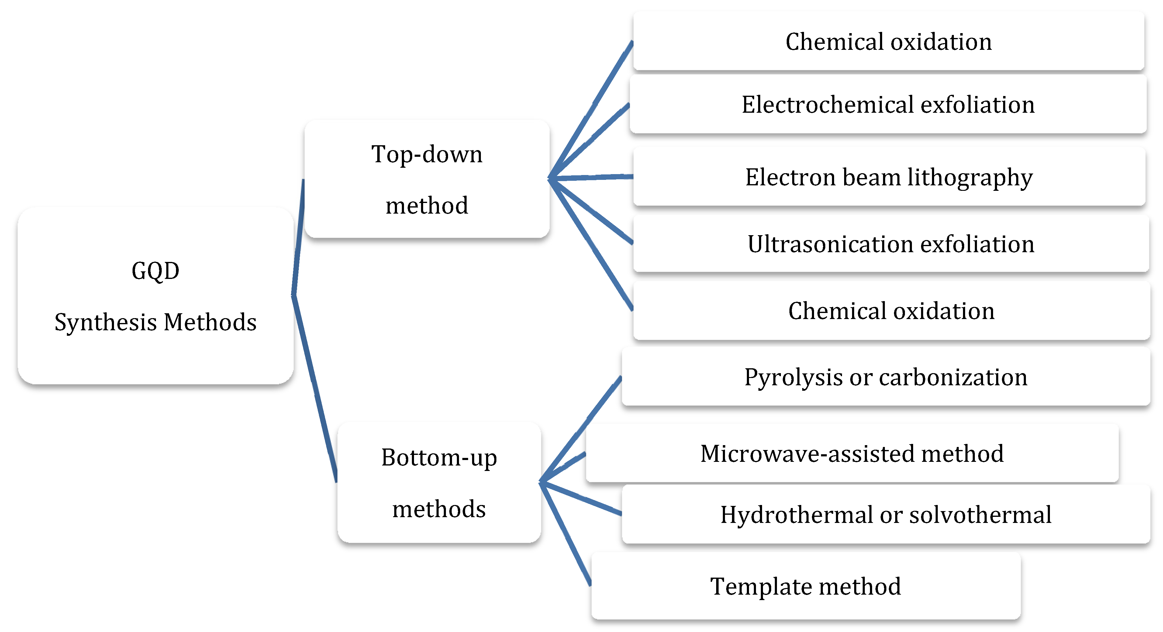
3.1. Synthesis Methods

Methods of GQDs synthesis can be categorized into two main groups, namely bottom-up and top-down production methods, as shown in Figure 5. Top-down procedures include chemical oxidation, electrochemical exfoliation, laser exfoliation, and chemical exfoliation [61,62]. These are applied by incising large graphene sheets, CNTs, carbon fibers, or the graphite into smaller segments of graphene sheets. These methods are considered the most appropriate methods for mass production. Bottom-up methods consist of GQDs synthesis using polycyclic aromatic compositions or molecules with aromatic structures such as fullerenes via pyrolysis or carbonization [63].

3.2. Optical Properties of GQDs

The optical properties of GQDs have been thoroughly investigated using UV–Vis and PL spectroscopy [64].

3.2.1. UV–Visible Spectroscopy

The basic properties of GQDs are mainly dependent on the shape, size, and edge structures, which play an active role in the positioning of absorption peaks in UV–Vis spectra. The other influential factors include functional groups, solvent exposure, and temperature exposure. As observed from multiple studies, GQDs show stronger optical absorption in the UV zone (260 to 320 nm) due to the p-p* transition of the C=C bonds, while the tail of its absorption spectra extends to the visible region [23]. Various GQDs demonstrate a sharp peak ranging between 270 and 390 nm, which shows a probable contribution from the n-p* transition of the C=O bonds.

3.2.2. PL Spectroscopy

The GQDs hold the graphene core and indeterminate chemical groups on their surface and thus the photoluminescence is organized together by the graphene core and neighboring chemical groups. GQDs exhibit greater quantum yield than the other carbon-based materials, which is due to the presence of layers in their structure and better crystallinity [65].
GQDs emit different colored photoluminescence contingent on their different synthesis methods, sizes, layered structures, chemical functionalization of their surfaces, and better crystallinity [23]. Figure 6a shows the fluorescence spectra of the GQDs at different pH levels. The other major contributing PL sites on the sample can vary while the wavelength of the excitation light changes, which can be clearly seen in Figure 6b. Many researchers report that the bandgap of GQDs is induced by their size and hence it can alter their PL. As the size of the GQDs decreases, the bandgap increases. The color of the PL spectra given in Figure 6c is associated with the sizes of GQDs and Figure 6d represents the energy bandgap with respect to different sizes of GQDs. Figure 6e reveals the PL emission of the GQDs in distinct liquid solvents. The peak shifted from 475 to 515 nm in tetrahydrofuran (THF), acetone, Dimethylformamide (DMF), and water, respectively. It is believed that the dielectric constant of the solvent from the GQD determines its emission efficiency in the solvent medium.

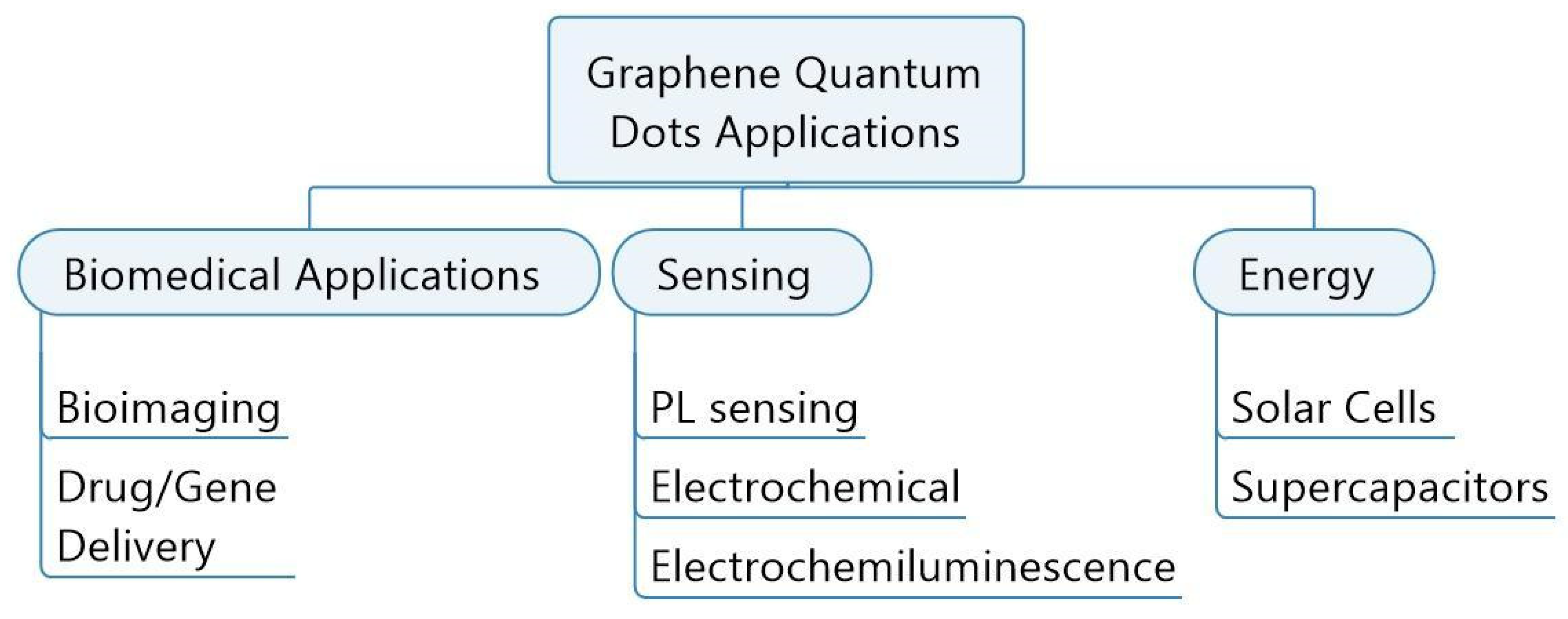
3.3. Applications of GQDs

The wide-ranging properties of GQDs make them suitable for use in diverse areas, among which biomedical, sensing, and energy applications can be mentioned. The specific applications in all these areas are listed in Figure 7 [56,66].

4. TiO2-GQDs Nanocomposites

TiO2-GQDs nanocomposites exhibit remarkable properties and superior performance compared to pristine GQDs and TiO2 nanoparticles. In this review, we present a timely survey of the synthesis aspects and photocatalytic mechanisms of the TiO2-GQDs nanocomposites. This is followed by a detailed discussion of the structural characterization of these composites. Further, the applications of TiO2-GQDs nanocomposites are systematically elucidated with suitable examples in the field of energy and biomedicine. Finally, current challenges and future prospects on the applications of TiO2-GQD-based composites are also discussed.

5. Synthesis of TiO2-GQD Nanocomposites

Material synthesis is an integral part of material research and industrial development. The properties of nanomaterials can be tailored by varying the methods of synthesis [67]. TiO2 and carbon-based nanomaterials such as GQDs are the most studied compounds in materials science, with more than 10,000 publications over the past 10 years [68]. Many excellent reviews and reports have been published on the preparation of TiO2 and GQDs recently; however, the synthesis methods for TiO2-GQD composite materials have not been reviewed comprehensively to date. This section provides an extensive overview of research that has been conducted in this field.
The most common methods to synthesize TiO2-GQD nanocomposites can be divided into three sections:
1. Synthesis methods for TiO2-GQD-doped nanocomposites;
2. Synthesis methods for TiO2-GQD-deposited/coated nanocomposites;
3. Synthesis methods for TiO2-GQD nanocomposite photoelectrodes.

5.1. Synthesis Methods for TiO2-GQD-Doped Nanocomposites

The most common methods to synthesize TiO2-GQD-doped nanocomposites are the hydrothermal method, ultrasound assisted hydrothermal method, microwave method, and physical mixing methods which involve mechanical stirring or ultrasound treatment to mix the TiO2 and GQD nanomaterials [69]. These methods are generally used to synthesize the physical/chemical mixture of TiO2 and GQDs nanoparticles. If the concentration of one of the nanomaterials (in the composite material) is less than ~5%, the obtained material can be called a doped material.

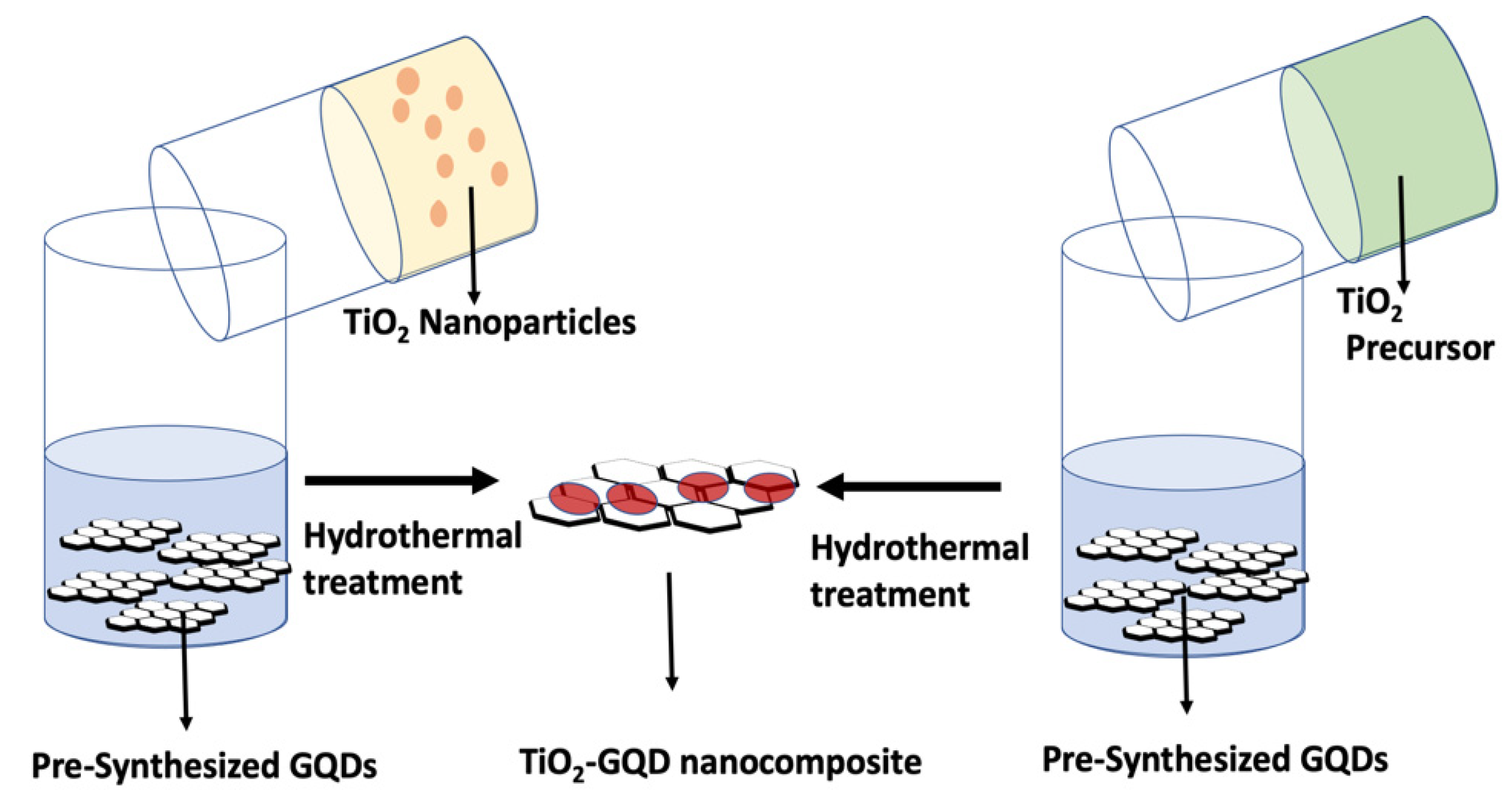
5.1.1. Hydrothermal Method

The hydrothermal synthesis method is the most common method for synthesizing TiO2-GQD composite nanomaterials. In this method, pre-synthesized GQD nanomaterials are mixed in aqueous solution with a precursor of TiO2 nanomaterials (such as Ti-isopropoxide or Ti-butoxide) or with pre-synthesized TiO2 nanomaterials. This mixture is then mechanically stirred at room temperature to obtain a homogeneous suspension. This suspension is placed in an environment with controlled temperature and pressure via steel pressure vessels with Teflon liners (autoclaves) [70]. The temperature and the amount of solution added to the autoclave largely determine the internal pressure produced. The schematics of hydrothermal preparation of TiO2-GQDs composite nanomaterials are given in Figure 8. Many groups, such as Pan et al., used pre-synthesized TiO2 and GQD nanoparticles to prepare TiO2-GQD nanocomposites via the hydrothermal method [71]. Xie et al. used Degussa TiO2 and GQD nanoparticles for synthesizing composite nanomaterials [72].
Biswas et al. used pre-synthesized GQD nanoparticles and mixed them with a titanium isopropoxide solution in which isopropyl alcohol and glycolic acid were used as solvents [73]. The synthesis methods where nonaqueous solvents are used are known as solvothermal methods. Nonaqueous solvents are generally used to enhance the solubility of titanium precursors such as titanium isopropoxide and titanium butoxide. In the solvothermal method, the temperature can be elevated much higher than that of the hydrothermal method, since a variety of organic solvents with high boiling points can be chosen. The precipitates obtained by this method are washed by centrifugation and dried in a vacuum. The most effective junctions of GQDs with TiO2 nanoparticles could be established by hydrothermal/solvothermal methods of synthesis.

5.1.2. Ultrasound-Assisted Hydrothermal Methods

This method is almost identical to the hydrothermal/solvothermal method, except that before the hydrothermal treatment, the suspension of the precursor solution is subjected to ultrasound treatments. Yan et al. have successfully synthesized TiO2-GQD nanocomposites by this method [74]. In this synthesis, an aqueous solution of GQDs is added dropwise to a mixture of titanium isopropoxide and ethanol under sonication and kept overnight with vigorous stirring. The entire solution is then subjected to solvothermal treatment to obtain TiO2-GQD nanocomposites. Ultrasound-assisted synthesis aids in the preparation of uniformly distributed and uniformly sized nanocomposites in a short time frame while utilizing less energy than traditional methods.

5.1.3. Microwave Method

In this method, a dielectric material can be processed with energy in the form of high-frequency electromagnetic waves. The principal frequencies of microwave heating are between 900 and 2450 MHz. At higher frequencies, the energy absorption occurs primarily due to molecules with permanent dipoles, which tend to reorientate under the influence of a microwave electric field. This reorientation loss mechanism originates from the inability of the polarization to follow extremely rapid reversals of the electric field, so the polarization phasor lags behind the applied electric field. This ensures that the resulting current density has a component in phase with the field, and therefore power is dissipated in the dielectric material [75]. The major advantages of using microwaves for industrial processing are rapid heat transfer and volumetric and selective heating.
Yang et al. developed a photoelectrochemical glucose sensor using the combination of TiO2-GQDs and polydopamine (PDA) nanocomposites [76]. In this research, titanium nanoarray (TiO2-NA)-PDA nanocomposites are prepared by an electrodeposition method. Further, the TiO2-NA-PDA electrode is combined with the GQD nanoparticles using the microwave method. The TiO2-NA-PDA substrate is immersed in a solution of 2 mL of GQDs, 3 mL of water, and 30 mL of ethylene glycol and subjected to microwave treatment for 1 min. Here, ethylene glycol is used as a dielectric material. The obtained substrate is rinsed with ethanol and water for further usage.

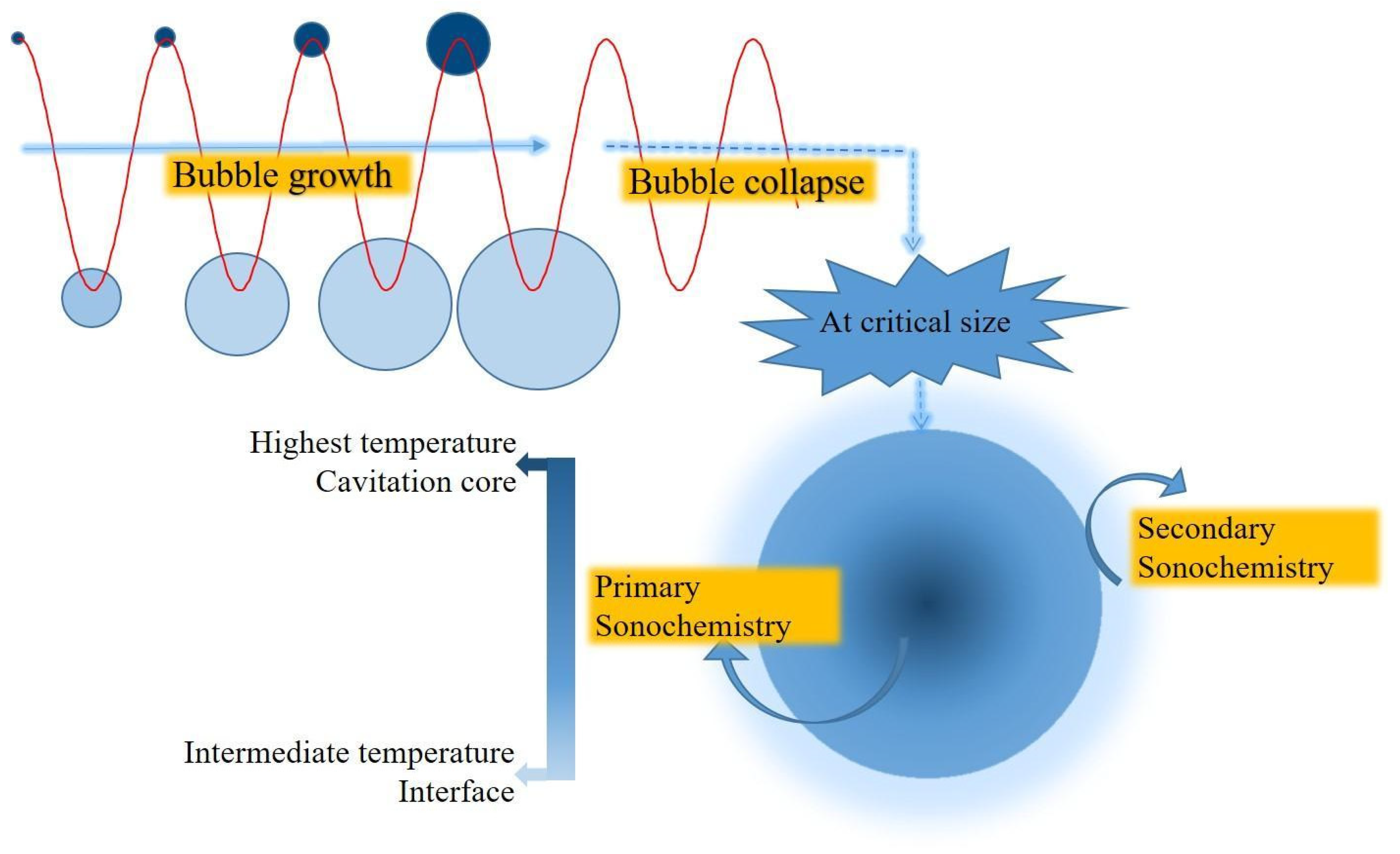
5.1.4. Sonochemical Method

Ultrasound has been very useful in the synthesis of a wide range of nanostructured materials, including high-surface-area transition metals, alloys, carbides, oxides, and colloids. The chemical effects of ultrasound do not come from a direct interaction with molecular species. Instead, sonochemistry arises from acoustic cavitation: the formation, growth, and implosive collapse of bubbles in a liquid. Cavitational collapse produces intense local heating (5000 K), high pressures (1000 atm), and enormous heating and cooling rates (>109 K/s) [77]. A scheme of the reactions occurring during the sonochemical process is depicted in Figure 9. The sonochemical method has been applied to prepare TiO2-GQDs nanocomposites by Sowba et al. In this method, pre-synthesized TiO2 and GQD nanoparticles are mixed in water and subjected to an ultrasound frequency of ~40 kHz for 1 h. These suspensions are then used for photocatalytic degradation reactions [78].
Shafee et al. synthesized GQDs-doped TiO2 by using the hydrothermal as well as sonochemical method and compared their photocatalytic activities for RhB dye degradation [79]. Results indicated that the TiO2-GQDs nanocomposites synthesized by the hydrothermal method showed slightly better photocatalytic activity than those synthesized by the sonochemical method.

5.1.5. Coupling Reaction

Chan et al. have reported TiO2-GQDs nanocomposite synthesis by the coupling reaction between carboxyl-containing GQDs and amine-functionalized TiO2 nanotube arrays (TNAs) [80]. TiO2 nanotube arrays are prepared by an anodic oxidation method and GQDs by an acid reflux method. The reaction scheme for the composite synthesis is given in Figure 10.
TNAs were firstly immersed in 0.2 wt % (3-aminopropyl) trimethoxysilane (APTMS) in toluene for 3 h, rinsed with toluene, and dried. The modified TNAs were then immersed in a beaker containing a solution of GQDs (1 mg·mL−1), ethyl(dimethylaminopropyl)carbodiimide (EDC), and N-hydroxysuccinimide (NHS) for 4 h. The foils were then sonicated in DI water, rinsed with DI water, and dried in air.

5.1.6. Physical Mixing

This is the simplest method used for the preparation of TiO2-GQDs nanocomposites. In this method, both pre-synthesized TiO2 and GQDs nanomaterials are electromagnetically/mechanically stirred for at least 24 h. Many researchers, including Sun et al. and Qu et al., have reported the synthesis of TiO2-GQD nanocomposites by this method [81,82]. Sun et al. have used a P-25 TiO2 (Degussa TiO2) nanomaterial which is dispersed into an aqueous solution of GQDs and kept under stirring for 24 h. The obtained composites were collected by centrifugation at 8500 rpm for 30 min. The solid was dried at 70 °C for 24 h.

5.2. Synthesis Methods for the Deposited Materials

These methods are employed to deposit one of the nanomaterials (TiO2 or GQDs) on the surfaces of other (pre-synthesized) nanomaterials. These synthesis methods for deposited materials include, but are not limited to, the liquid/wet impregnation method, electrocatalytic deposition, the spin-coating method, and photoreduction methods. A detailed description of all these methods is given below.

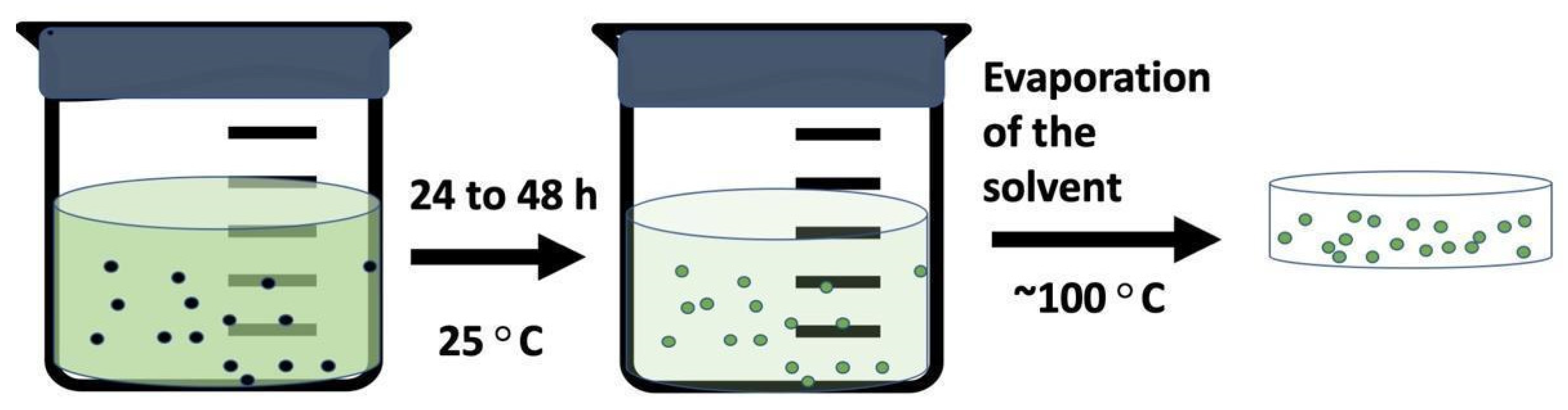
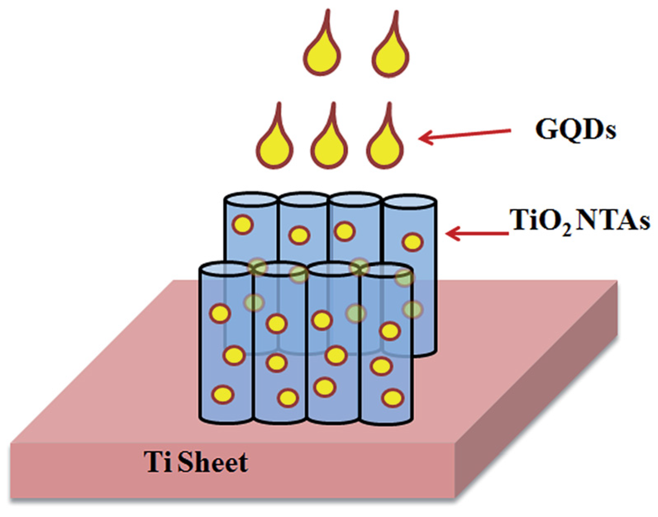
5.2.1. Liquid Impregnation Method

Wet impregnation is a well-known method in the development of heterogeneous catalysts. This is a procedure whereby a certain volume of solution containing the precursor of the active phase is placed into contact with another active solid phase (support), which, in a subsequent step, is dried to remove the imbibed solvent [83]. Thus, this method can be used to prepare supported and mixed catalysts. A schematic overview of this process is given in Figure 11. Yu et al. have developed TiO2-GQDs nanocomposites by this method [84]. In this method, TiO2 nanoparticles are immersed in a 0.01-mg/mL graphene oxide quantum dot (GOQD) aqueous solution (15 mL) for 5 h. After slow evaporation at 40 °C, the GOQD-TiO2 composites are produced. Then, the black GQDs-TiO2 was obtained through annealing treatment of GOQD-TiO2 at 450 °C in an argon stream for 1 h.

5.2.2. Electrocatalytic Deposition

Electrodeposition is commonly employed to produce a coating, usually metallic, on a surface by the action of reduction at cathode. The substrate to be coated is used as a cathode and immersed into a solution which contains the salt of the metal to be deposited [85]. Xu et al. fabricated GQDs deposited onto TiO2 using electrodeposition [86]. In this method, different TiO2 films (micropillars and microcave arrays of rutile TiO2) act as working electrodes and Pt plates act as a counter electrode. These electrodes are immersed in an aqueous GQDs solution. The pH of the GQDs solution is tuned to 8 in order to increase the negative charges on the GQDs nanoparticles. Under an applied positive potential of 6 V for 1 h, the functional GQDs were spontaneously deposited onto the surfaces of the nanorods. Similar procedures have been employed by Sudhgar et al. to prepare GQD-decorated TiO2 Nanowires [87].

5.2.3. Photodeposition Method

Illumination of a slurry of semiconductor particles in an aqueous-phase solution of a metal salt often results in the deposition of well-defined metal (oxide) nanoparticles on the surface of the semiconductor: this phenomenon is generally known as photodeposition [88]. Hao et al. synthesized water-soluble and well-crystallized GQDs by the hydrothermal cutting method. These GQD nanomaterials are anchored on TiO2 by an in-situ photo-assisted strategy under UV–Vis light irradiation [89].

5.2.4. Spin-Coating Method

Spin-coating is a low-cost method used to deposit uniform thin films on the flat substrates. When a solution of a material is spun on a substrate at high speed, the centripetal force and the surface tension of the liquid can create an even covering of the solution on the substrate. After any remaining solvent has evaporated, spin-coating results in a thin film ranging from a few nanometers to a few micrometers in thickness [90]. A schematic overview of spin-coating method is shown in Figure 12. Bayat et al. used a hydrothermal method to synthesize GQDs and to grow TiO2 nanoflowers (NFs) on Fluorine doped Tin Oxide (FTO) glass. Various amounts of GQDs were dropped on the TiO2 NF substrate a under rotation speed and deposition time of 3000 rpm and 3 min, respectively [91]. Then, these GQDs-TiO2 photoanodes were heated for 30 min in an oven at 200 °C for better tenacity of GQDs on the TiO2 NFs’ surfaces.

5.2.5. Drop-Cast Method

For small substrates (~1 cm2), an easy and tunable deposition method is drop-casting. The drop-cast method involves the release of large droplets with controlled sizes and momentum that spread a nanoparticle dispersion over a substrate and allow it to dry under controlled condition. The thickness of the film depends upon the volume of the dispersion used and the particle concentration [92]. Gupta et al. synthesized vertically aligned TiO2 3D nanotube arrays by anodic oxidation of Ti sheets. Graphene quantum dots were synthesized using acid treatment and chemical exfoliation of multi-walled carbon fibers. These GQDs were dispersed into an ethanol solution via ultrasonication at a frequency of 25 kHz for 1 h to form a homogeneous suspension with a concentration of 0.05 mg/mL. The resultant solution was drop-casted on the mouth surface of the highly oriented TiO2 3D nanotube arrays (NTAs) (40 V, 4 h, 500 °C) using a micro-syringe, as shown in Figure 13. This is a highly efficient technique to fill the GQDs into the TiO2 nanotubes as it provides the entry of the GQDs through the hollow mouth of the TiO2 nanotubes within a few seconds [93].

5.3. Synthesis Methods for TiO2-GQD Photoelectrodes for Solar Cell Applications

For solar cell applications, TiO2-GQD nanoparticles have to be synthesized in the form of thin films. The thin film assembly begins with the preparation of the substrates.

5.3.1. Preparation of Substrates

Generally, fluorine-doped tin oxide (F: SnO2)-coated glass (FTO) is used as the substrate. FTO is patterned by etching with 2 M HCl and Zn powder. The patterned FTO is cleaned by ultrasonication and rinsed with detergent, deionized water, ethanol, acetone, and isopropanol for 30 min, respectively. Then, the FTO is dried by clean air and treated with a UV-ozone machine for 15 min.

5.3.2. Deposition of TiO2 Layer

TiO2 thin layers can be deposited on the substrate by using the following methods: (A) doctor blade method B) drop-casting or spin-coating TiO2 paste onto the substrate, (C) growing TiO2 film on the substrate by hydrothermal or other methods.
A. Doctor blade method: This is the traditional and most common method to fabricate TiO2 photoanodes. In this method, pre-synthesized TiO2 nanoparticles are mixed with binders such as polyethylene glycol and Triton X-100 followed by a sufficient amount of distilled water to make it a viscous paste. TiO2 films are then fabricated via doctor blade printing on the substrate (FTO glass slides). The schematic of the doctor blade method is given in Figure 14 [94]. After drying, these as-fabricated TiO2 films are subjected to annealing at ~400 °C for better adhesion between the film and substrate. Kundu et al., Salam et al., Mustafa et al., and Subamanium et al. have reported TiO2 thin film preparation by this method [95,96,97,98]. Kundu et al. and Subramaniam et al. have modified this method by coating a TiO2 buffer layer (by immersing FTO substrate in 40 mM TiCl4 and drying at 70 °C) on the substrate before doctor blade printing [97,98].
Kumar et al. have reported a binder-free TiO2 paste preparation method in which 0.2 g of Degussa TiO2 nanoparticles and tetra butyl alcohol are refluxed in acidic (HNO3) medium with the addition of distilled water. The contents were stirred for 8 h at room temperature. TiO2 films were then prepared by the doctor blading method [99].
B. Spin-coating/screen printing: The details of the spin-coating method are explained in Section 4.1.2.E. Shen et al. reported TiO2 electrode preparation by spin-coating [100]. In this method, a TiO2 blocking layer is prepared on the substrate by spin-coating a precursor solution of 0.15 M titanium diisopropoxide bis(acetylacetonate) (75 wt % in isopropanol, Alfa-Aesar) in 1-butanol. After spin-coating, the substrates are annealed at 550 °C for 30 min and then they are left to cool down to room temperature. The mesoporous TiO2 (mp-TiO2) layer is deposited by spin-coating for 30 s at 2000 r.p.m/min, using a 25-nm-particle home-made paste diluted in ethanol (0.1 g mL−1). Finally, the substrate is immediately dried at 150 °C for 30 min and sintered again at 550 °C for 30 min.
The principle of screen printing is shown in Figure 15. In this technique, a paste of the material to be screen printed is pressed through the screen by means of a squeegee. Important screen-printing parameters are the viscosity of the paste, the mesh number of the screen (# of meshes per inch), the snap-off distance between the screen and the substrate, and the pressure and speed of the squeegee. After leveling, the printed wet film is dried (e.g., at 120 °C, 60 min). By then, the film consists of loose conglomerates of very small grains (1–2 µm). The sintering step results in a compact film. Sharif et al. and Lee et al. have reported the preparation of TiO2 thin films by the screen printing method using TiO2 paste [101,102].
C. Hydrothermal method: Some researchers directly grow TiO2 films on FTO substrates using the hydrothermal method and subsequently use them as a photoelectrode in a solar cell. In this method, clean FTO slides are placed inside an autoclave. A transparent mixture of titanium isopropoxide, hydrochloric acid, and distilled water is placed in the same autoclave. Then, the hydrothermal process is carried out at 160 °C for 15 h in the oven. The details of hydrothermal synthesis are given in Section 4.1.1.A. Jahantigh et al. and Khorshid et al. have reported photoelectrode preparation by this method [103,104].
D. Deposition of GQDs and dye on TiO2 films: Generally, in solar assemblies, a dye layer is deposited on the TiO2 layer, which absorbs and transfers the maximum incident light to the TiO2. When TiO2-GQD nanocomposites are used in the solar cells instead of pure TiO2, most researchers deposit both the GQD and dye layer on TiO2 by a wet impregnation method 33. This is a very simple method in which TiO2 thin films are immersed in the GQD solution for 24 to 48 h. Then, the films are washed with DI water to remove excess GQDs which were physically absorbed on the TiO2 films. Other methods such as spin-coating and screen painting can also be used for GQD deposition and dye deposition on the TiO2 layer.

6. Structural Details of TiO2-GQD Nanocomposites

The properties and photocatalytic applications of TiO2-GQDs nanocomposites depend mainly on the structure, morphology, and the surface properties of the prepared nanocomposites. Therefore, various characterization techniques are employed for the characterization of TiO2-GQDs nanocomposites used for photocatalytic applications. The most relevant of these techniques are reviewed below, using representative examples.

6.1. XRD Pattern

X-ray powder diffraction is most widely used for the identification of unknown crystalline materials (e.g., minerals, inorganic compounds). It provides complete information about the crystal phase structure and phase purity of crystalline materials. Interaction of cones of X-rays is related to interplanar spacings in the crystalline powder according to a mathematical relation called “Bragg’s Law” [105].
nλ = 2d sinθ
where n is an integer;
λ is the wavelength of X-rays;
d is the interplanar spacing generating the diffraction, and
θ is the diffraction angle.
XRD requires a highly ordered crystal lattice structure in order to provide useful information. For very small-grain-sized and amorphous structures, it will produce a large number of diffraction points, leading to a broad diffraction peak [106]. Hence, for most of the GQD nanoparticles, the diffraction peak is broad and noisy, which can be attributed to their low crystallinity and small size. A GQD diffraction pattern reported by Gupta et al. is presented Figure 19a. The broad diffraction peak centered at 2θ = 24.4° is attributed to the (002) plane of the carbon structure with a hexagonal phase (JCPDS no. 75-162) [93].
Figure 16b,c represent the XRD patterns of the GQD-infilled TiO2 nanoparticles and pure TiO2 nanoparticles, respectively. Figure 16c represents the diffraction patterns of pure TiO2. The quantitative analysis of Figure 16c shows that all of the diffraction peaks can be ascribed to the TiO2 and Ti substrate. The typical diffraction peak (101) centered at 25.1 indicates the TiO2 anatase phase (JCPDS no. 21-1272). The peaks correspond to the (101), (103), (004), (112), (200), (105), (211), (213), (116), and (220) planes of the anatase phase with a tetragonal crystal structure with space group I41/amd (141). As can be noted from Figure 16b, no peaks from the carbon species are present in the diffraction pattern. This can be due to the small amount and weak intensity of the GQDs. Moreover, the main peak of graphene (2θ = 24°) may have been shielded by the main peak of anatase TiO2 at (2θ = 25.1°). Similar to the XRD plots acquired by Gupta et al., the peak from the GQDs is usually absent in the diffraction pattern of the TiO2-GQD nanocomposites.
In some cases, where a large amount of GQDs is coupled with TiO2, the GQD peak can be seen in the diffraction pattern of the composite. Rajinder et al. use equal weights of TiO2 and GQDs to synthesize TiO2-GQDs nanocomposites, whose diffraction pattern can be seen in Figure 16d,e [107]. The most intense peak at 2θ = 25° corresponds to the anatase phase (101) plane of TiO2. Along with this, another intense peak at 2θ = 26.3° can be seen and is attributed to the (002) plane of hexagonal sp2 hybridized carbon in GQDs. The (002) peak is very intense as the hybrid sample is prepared with an equal weight ratio of TiO2 and GQDs. These results indicate the successful preparation of TiO2-GQD hybrids with crystalline phases.

6.2. Raman and FTIR Spectroscopy

Raman and FTIR spectroscopy are two complementary techniques which provide detailed information about chemical structure, phase and polymorphy, crystallinity, and molecular interactions. Raman spectroscopy is used to confirm the formation of the TiO2 anatase phase and the existence of GQDs in the TiO2-GQD nanocomposites. In addition to this, it is an important tool to deduce the structure related to the quality and number of graphene layers, nature of defects and disorder, and doping level in graphene-based materials. The Raman spectra of the TiO2 and GQD-infilled TiO2 synthesized by Gupta et al. are shown in Figure 17a [93]. Raman characteristic peaks for both samples at around 394, 516, and 642 cm−1 are obtained, which correspond to the B1g, A1g + B1g, and Eg modes of vibration of the anatase phase of TiO2, respectively. Two additional peaks at around 1354 and 1600 cm−1 for the graphene structure are also observed in the Raman spectrum of the GQD-infilled TiO2 (Figure 17a), which can be assigned to disordered sp2 carbon (D-band) and well-ordered graphite (G-band), respectively. The intensity ratio of the D- to G-band (ID/IG. 0.846) indicates a disorder in graphene, which originates from defects associated with grain boundaries, vacancies, and amorphous carbon.
The formation of Ti-C and Ti-O-C chemical bonds in TiO2-GQD nanocomposites can be confirmed by FTIR. As shown in Figure 17b, the broad absorption band at ~3432 cm1 corresponds to the hydrogen-bonded O-H stretching vibration [89]. The characteristic absorption peaks at ~3432 cm−1 are assigned to the C-H stretching vibration; peaks at ~1593 and ~1416 cm−1 are related to O-C-O asymmetric and symmetric vibrations; the peaks at ~1090 and ~990 cm−1 are related to the C-O bonds and epoxy groups. The broad absorption bands at 480–700 cm−1 are attributed to the stretching vibrations of Ti-O-Ti and Ti-O-C vibrations, indicating that the GQDs have been successfully attached to the TiO2 nanoparticles.

6.3. UV–Vis and Photoluminescence Spectroscopy

UV–visible spectroscopy is the main technique used to study the optical properties of nanoparticles. As mentioned earlier, coupling GQDs with TiO2 results in the bandgap narrowing of the composites. UV–visible spectra of pure TiO2 and TiO2-GQD nanocomposites (with different weight percentages of GQDs) prepared by Lim et al. are shown in Figure 18a [108]. As can be seen from Figure 18a, the pure TiO2 spectrum shows a characteristic cut-off wavelength at ~384 nm. As compared with pure TiO2, composite samples show a significant red shift in their absorption edge with increasing wt% of GQDs. In addition to this, the intensity of all composite spectra appears to be higher than that of the TiO2 sample. This indicates that the incorporation of GQDs not only reduces the bandgap of TiO2 but also increases the visible light absorption of TiO2.
The study of the recombination rate between photoinduced electrons and holes is a very crucial factor for the photocatalytic activity of TiO2-GQDs nanocomposites. Photoluminescence (PL) emission spectra could help to directly elucidate the behaviors of photoinduced electrons and holes and highlight their radiative recombination. Generally, PL emission signals are caused by the photoinduced carrier recombination process. Incorporation of GQDs into TiO2 is often associated with a decreased rate of recombination and hence lower PL intensity signal of composite TiO2.
Ou et al. have synthesized different types of TiO2 samples and coupled them with GQDs. The PL spectra of all these samples are given in Figure 18b [109]. As can be seen in Figure 18b, all the GQD-coupled TiO2 samples show lower intensity than the TiO2 sample. GQDs have discrete electronic levels, allowing for hot electron injection and efficient spatial separation of electrons and holes, and this reduces their geminate recombination.

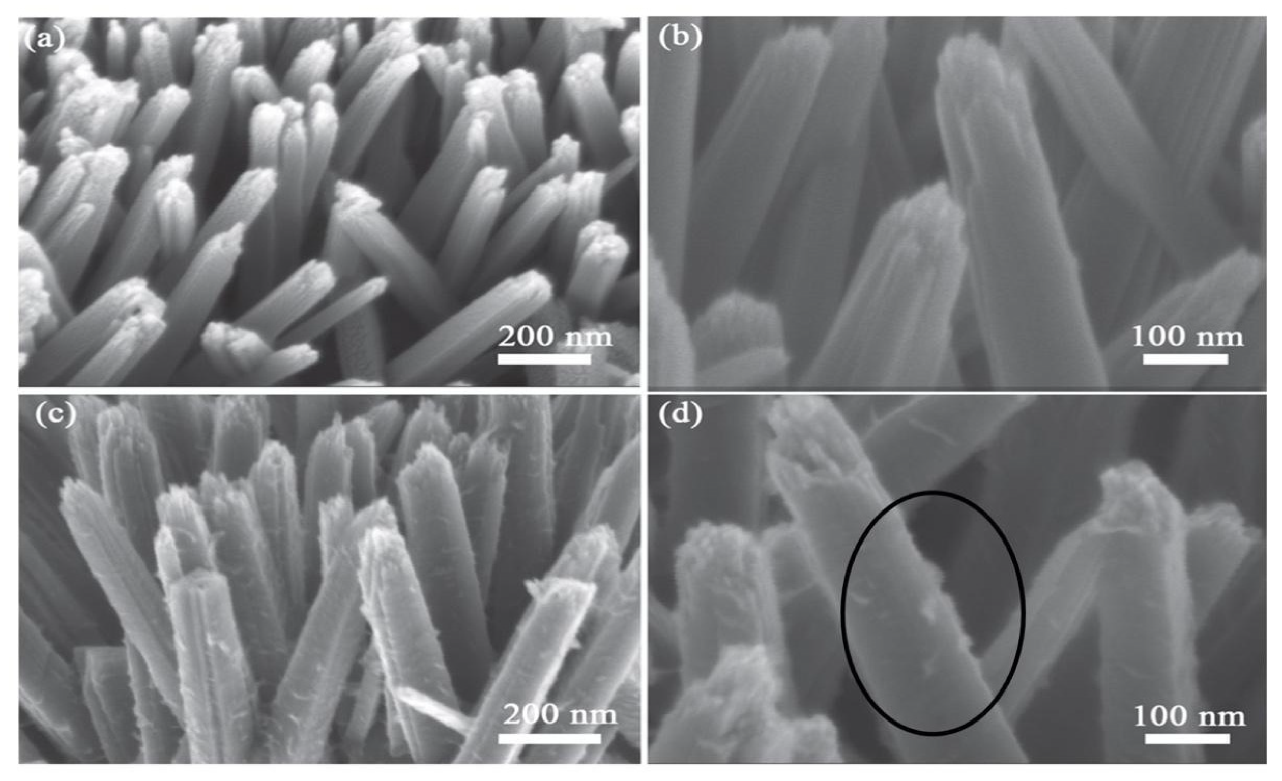
6.4. SEM and TEM Analysis
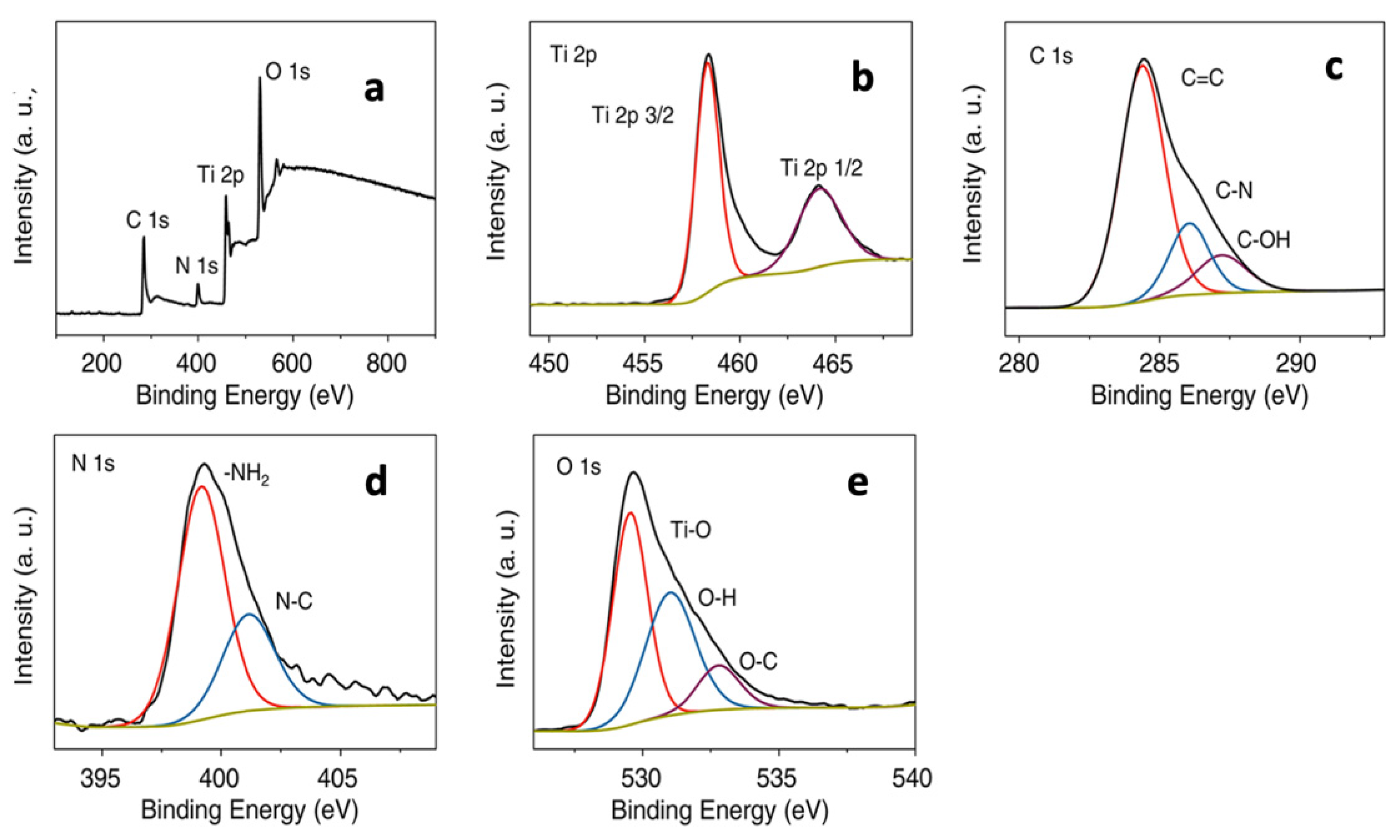
Scanning electron microscopy is a versatile, nondestructive technique that reveals detailed information about the morphology and the composition of nanomaterials. It provides three-dimensional images of the nanomaterials which are very useful for judging the surface structure and topography of the samples.
Xu et al. have synthesized micropillar (MP) and microcave (MC) arrays of anatase TiO2 films through the sol–gel-based thermal nanoimprinting method [86]. Then, those (MP) and (MC) arrays are employed as seed layers in hydrothermal growth to fabricate the 3D micropillar/microcave arrays of rutile TiO2NRs (NR). After hydrothermal growth, all the obtained nanorods exhibit uniform dimensions of around 100 nm in diameter and 2–3 μm in length, which can be clearly seen in Figure 19a,b. Moreover, they exhibit a relatively smooth side surface with a rectangular cross-section. GQDs are then deposited on these TiO2 NRs by an electrophoresis method, as shown in Figure 19c,d. As can be noted from Figure 19c–d, the surface of the nanorods becomes much rougher, indicating that the GQDs are homogeneously deposited on the entire surface of the nanorods.
The possibility for high magnification has made TEM a valuable tool in material research. It is a very useful technique for confirming the size, shape, and arrangement of the nanoparticles in a specimen. Direct information about the structure can be obtained by high-resolution transmission electron microscopy (HRTEM). It is highly useful for the determination of lattice planes and the detection of atomic-scale defects localized in areas of a few nanometers in diameter with the help of the selected area electron diffraction (SAED) technique.
The TEM analysis of rutile TiO2 nanotube arrays, GQDs, and GQD-deposited TiO2 nanotube arrays is shown in Figure 20 [86]. The SEM images of the same samples are shown in Figure 19. Figure 20a shows an HRTEM image of an individual pure TiO2 nanorod with a highly resolved (110) lattice fringe of rutile TiO2 (d = 0.32 nm), demonstrating that the nanorod grows preferentially along the [001] direction. The diameter of the nanorod is around 100 nm (inset of Figure 23a), which is consistent with the SEM result in Figure 19b. Figure 20b shows a representative low-magnification transmission electron microscope (TEM) image of the GQDs, which are uniformly distributed on the TEM carbon film without aggregation. The size of the GQDs is around 3–5 nm. The corresponding HRTEM image (Figure 20c) shows the lattice spacing of 0.21 nm related to the (1100) plane of GQDs. The lattice-resolved TEM image of TiO2NR-GQDs in Figure 20d reveals clear lattice fringes with interplanar spacings of 0.32 and 0.21 nm, which are consistent with the (110) plane of rutile TiO2 and (1100) plane of GQDs. This indicates that the GQDs attach onto the TiO2 nanorods firmly, which confirms the results obtained from SEM analysis of these samples.

6.5. XPS Analysis

XPS spectra are used to determine the chemical states of Ti, O, and C species and characteristic bonding between the TiO2 and GQD through the formation of Ti-C and Ti-O-C bonds. Pan et al. have synthesized amine functionalized-GQD by the alkali-catalyzed water-phase molecular fusion method. These GQDs are coupled with TiO2 nanoparticles by a hydrothermal method. The XPS spectra of these nanoparticles are given in Figure 21 [71].
The survey XPS spectra are given in Figure 21a, which shows three intense peaks around 285, 460, and 531 eV corresponding to C 1s, Ti 2p, and O 1s, respectively. A weak signal from N indicates that the GQDs are doped with N. The peak of Ti 2p in the survey spectra around 460 eV can also be deconvoluted into two components at 464.6 and 459 eV, as shown in Figure 21b. These peaks correspond to Ti 2p1/2 and Ti 2p3/2, indicating that the metal is present in the Ti (IV) state in the composite. The C 1s spectrum presented in Figure 21c can be deconvoluted into three components with the binding energy of C=C at 284.2 eV, C-N at 285.4 eV, and the distinguishable C-OH peak at 286.9 eV. Two peaks at 399.2 and 401.2 eV in the N 1s XPS spectrum (Figure 21d) are assigned to NH2 and N-C bonding of the GQDs. The peaks at 529.2, 531.1, and 533.1 eV in the O 1s spectrum (Figure 21e) are assigned to the Ti-O, O-H, and O-C bonding, respectively. A peak around 530.8–531.4 eV in the deconvoluted O 1s spectrum also correlates to the formation of the Ti-O-C bond in the nanocomposite, suggesting the formation of a GQD/TiO2 nanocomposite.

6.6. N2-BET Surface Area Analysis

This technique provides detailed information about the specific surface area, pore volume, and pore size distributions of samples.
Zhang et al. have reported the synthesis of hollow titanium oxide (H-TiO2) nanospheres and graphene quantum dot nanoparticles by a simple hydrothermal method [110]. N2 adsorption/desorption isotherms of these (H-TiO2) and H-TiO2-GQD nanocomposites are given in Figure 22. Both the isotherms can be assigned to the typical type IV, with a hysteresis loop at the relatively higher pressure of 0.45. This indicates that both the samples are mesoporous in nature. The average pore diameter (as shown in Figure 25b) is found to be around 2.5–7 nm. As the GQD synthesized in this work has a size of around 5 nm, it plays a very important role in increasing the mesoporosity of the composite sample. In addition to this, GQDs provide additional surface area to the composite material, which allows greater adsorption of the contaminants.

7. Mechanism of Photocatalysis on TiO2-GQD Nanocomposites

7.1. Mechanism of Photocatalysis on TiO2

The general mechanism of photocatalysis on TiO2 involves three major steps, i.e., photoexcitation, recombination, and oxidation-reduction reactions, which can be seen in Figure 23a [111]. In all photocatalysis reactions, TiIV represents the four coordinated surface functionalities of TiO2 or the “active site”. Hoffmann et al. have found by laser flash photolysis studies that the characteristic time scale for the generation of charge carriers is in the order of femtoseconds (fs) [112]. The charge carriers generated become trapped onto the TiO2 surface, which occurs over a time scale of tens of nanoseconds (ns).
Step 1. Photoexcitation:
h ν >   E B G T i O 2   +   h ν     h V B +   +   e C B _
Reaction (3) represents the trapping of the holes by the surface hydroxyl groups present in TiO2, and Reactions (4) and (5) represent the reversible trapping of the electrons on the surface of TiO2 (shallow traps) and the irreversible trapping or relaxation of the electrons at the bottom of the conduction band (CB) (deep traps), respectively.
T i I V O H +   h V B +   T i I V O H
Surface   trap T i I V O H +   e C B   T i I I I O H
Deep   trap T i I V +   e C B _   T i I I I
Reactions (6)–(8) represent the electron-hole recombination reaction, which occurs at surface states of the TiO2, or in the bulk medium due to the delocalization of the electrons and holes. This is one of the detrimental reactions in photocatalysis as this affects the interfacial charge transfer processes and hence the quantum efficiency of the photoprocess.
Step 2. Electron-hole recombination:
T i I V O H +   e C B   T i I V O H   ( Free   electron   with   a   trapped   hole )  
T i I I I +   h V B + T i I V ( Free   electron   with   a   trapped   electron )
h V B + + e C B h e a t   ( Free   hole   with   free   electron )
Reaction (9) represents the generation of hydroxyl radicals (OH•) by the reaction of surface-adsorbed water molecules with the holes, and Reactions (10)–(15) show the formation of superoxide (O•−2), hydroperoxyl (HOO•), and hydroxyl species through the electron pathway. All the above radical species are referred to as the “active species”. When the reactions are carried out in nonaqueous (organic) medium, the surface-bound hydroxyl species present in the semiconductor play a major role (Reaction (2), and the contributions of Reactions (8)–(14) to the overall oxidation of the substrate are negligible).
Generation of hydroxyl radicals in the aqueous medium:
T i I V H 2 O + h V B + T i I V O H + H + ( Hole   pathway )
T i I I I + O 2 T i I V O 2
T i I V O 2 + 2 H + + e C B T i I V H 2   O 2
T i I V O 2 + H + T i I V H O 2
T i I V 2 H O 2 T i I V H 2   O 2 + O 2
T i I V H 2   O 2 + e C B T i I V O H + O H
T i I V H 2   O 2 + O 2 T i I V O H + O H + O 2
Once the active species are generated, the reactants are adsorbed onto the surface of the photocatalyst Reactions (16)–(18).
Adsorption/desorption of a reductant (any organic substrate S):
T i I V + S T i I V S
T i I V O H + S T i I V O H S
Adsorption/desorption of an oxidant (e.g., metal ion):
T i I V + M n +   T i I V M n +  
This is followed by the oxidation of the reductant and the concomitant reduction of the oxidant by the attack of the hydroxyl radicals and CB electrons, respectively (Reactions (19)–(22)). The above two processes occur at characteristic time scales of 100 ns and milliseconds, respectively. This means that the oxidizing power of the valence band (VB) hole or the hydroxyl radicals is always higher than that of the reducing power of the CB electrons. Moreover, these interfacial electron transfer steps compete with the electron-hole recombination Reaction (10 ns) and, hence, the practical efficiency or quantum yield is always less than that of the theoretical yield.
Photooxidation of a reductant:
Direct hole attack:
T i I V S + T i I V ( h V B + ) T i I V + T i I V I C O 2 + H 2 O
Hydroxyl radical attack:
T i I V S + T i I V O H T i I V + T i I V I C O 2 + H 2 O
T i I V S + O H T i I V I   C O 2 + H 2 O
T i I V O H S T i I V I C O 2 + H 2 O
The organic compounds degrade through the formation of intermediates (I), which transform finally to CO2 and H2O. Reaction (23) shows that the products desorb from the surface, thereby freeing the TiO2 active site. Similarly, when metal ions are present in the system, they are reduced to their thermodynamically stable oxidation states by the CB electrons (Reaction (24)).
Adsorption/desorption of the organic intermediate:
T i I V + I T i I V I
Photoreduction of a metal ion:
T i I V M n +   + m e T i I V M ( n m ) +  
Therefore, the overall photocatalysis reaction can be depicted as follows, wherein the oxidants are reduced, and the reductants are oxidized by the action of UV radiation on the semiconductor photocatalyst.
Step 3. Oxidation and reduction reactions:
( O X 1 ) a d s + ( R e d 2 ) a d s R e d 1 + O X 2

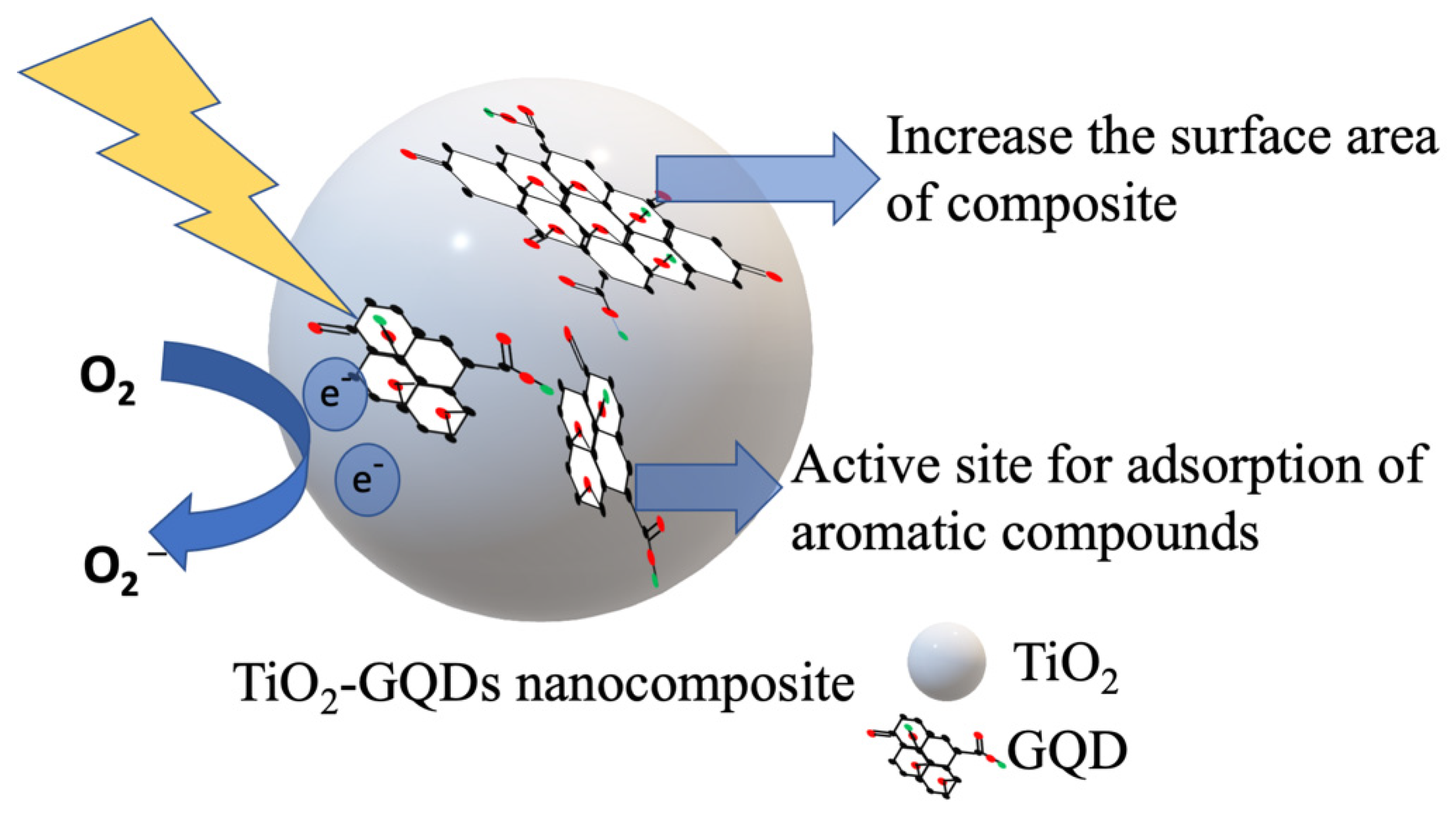
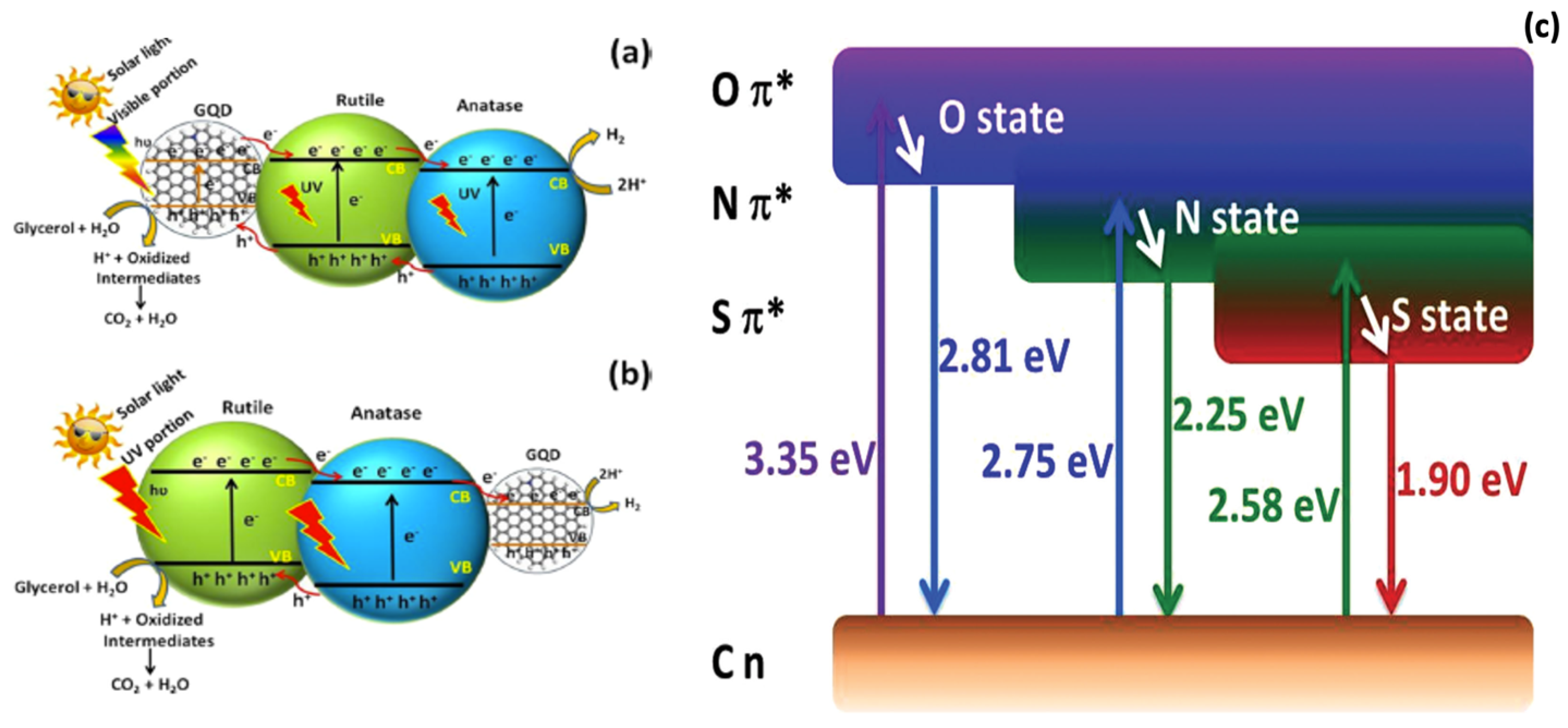
7.2. Mechanism of Photocatalysis on TiO2-GQD Nanocomposites

Though the photocatalytic degradation process on TiO2-GQDs nanocomposites follows the same steps, it shows improved photocatalytic performance. This improvement is achieved due to one or more of the following reasons:
1. As can be seen in Figure 23b, GQD has a narrower bandgap than TiO2 nanoparticles.
Hence, under visible light irradiation, GQDs act as photosensitizers to TiO2 and donate the electrons to the conduction band of TiO2. This increases the visible light absorption ability of the TiO2-GQD nanocomposites [87].
2. Discrete electronic levels and substantial electronic conductivity enable GQDs to act as an electron sink for photogenerated electrons. In addition to this, GQD-extended π-electron systems can be placed in direct contact with a TiO2 surface, facilitating donor–acceptor contact. The coupling can be enhanced further by covalent linking between GQDs and TiO2 through a variety of functional groups available due to the versatile chemistry of the carbon atom; these allow hot electron injection from TiO2 to the GQDs, resulting in efficient charge separation [34].
3. As shown in Figure 24, GQDs have a two-dimensional matt structure which is composed of a planar hexagonal lattice of carbon atoms with a C-C bond length of 1.42 Å. The atoms are connected by both σ-bonds formed by sp2-electrons and π-bonds formed by pz-electrons. These chemical features endow GQDs with many unique properties, such as high electron and hole mobilities and large surface area per unit of mass (up to ~2600 m2/g) [69].
4. Most of the organic pollutants/contaminants have aromatic structures. As the GQDs also have an aromatic nature, it acts as an active site for the adsorption of aromatic contaminants, which accelerates the rate of photodegradation [69].

8. Applications of TiO2-GQD Nanocomposites

8.1. Dye Degradation by TiO2-GQD Photocatalysts

Water pollution due to synthetic dyes is a matter of great concern. Dyes are toxic, carcinogenic, and mutagenic. As these dyes are synthetic, they are very stable in the presence of light and biodegradation, leading to their bioaccumulation in the food chain 111. Furthermore, a low concentration of dye can visibly contaminate water and reduce light penetration into water. This decreases photosynthesis underwater, which is a dangerous situation for aquatic flora and fauna [113]. TiO2 is one of the most promising materials for dye degradation applications. According to the literature, complete mineralization of synthetic dyes is possible using TiO2 as a catalyst [114]. However, the practical application of this is limited due to the wide bandgap, high recombination rate, and poor adsorption capacity of TiO2 nanoparticles [115]. Numerous research efforts have been employed to enhance the dye degradation performance of TiO2 via adding a secondary component, including metal, nonmetal, or other semiconductors [116,117]. Recently, enhancements of photocatalytic activity of TiO2 have been demonstrated by coupling TiO2 with carbonaceous substances such as fullerenes, carbon nanotubes, graphene, and particularly graphene quantum dots (GQDs) [113]. Due to quantum confinement and edge effects, GQD possesses a distinct bandgap and increment of surface area. Additionally, GQD possesses a high degree of crystallinity related to superior electron transport and charge separation [118].
The general experimental setup for the photocatalytic dye degradation is shown in Figure 25. The degradation is carried out in a cylindrical photoreactor surrounded by a circulating water jacket, which is used to maintain a constant temperature throughout the experiment. The experiments were conducted with a certain amount of dye solution with varying TiO2 photocatalyst dosages and initial dye concentrations. A UV or visible lamp, i.e., a light source, is kept at the top of the reactor. Prior to illumination, the suspension is magnetically stirred for some time to reach adsorption equilibrium and then stirred throughout the experiment to disperse the catalyst nanoparticles in the dye solution. A small amount of suspension is taken at regular time intervals and filtered or centrifuged to separate powder from the solution. The absorbance of the sample dye solution is measured with a UV spectrophotometer.
Table 1 lists several TiO2-GQD composites reported in the literature for dye degradation reactions. The most important contribution of GQD towards the higher photocatalytic activities of TiO2-GQD composites is enhanced visible light absorption. Pan et al. have reported a nine-times increase in the photocurrent intensity in response to visible light excitation after coupling amine functionalized GQD (N-GQD) with TiO2 [71]. N-GQDs have been synthesized by the alkali-catalyzed water-phase molecular fusion method and coupled with TiO2 through a simple hydrothermal method. This N-GQD-TiO2 showed a 15-times higher rate of MO dye degradation than the pure TiO2. Zhuo et al. have prepared anatase TiO2/GQD and rutile TiO2/GQD composites and compared their photocatalytic efficiency in visible light [119]. Generally, anatase TiO2 shows much higher photocatalytic activity than the rutile in visible light. However, in this case, the rutile TiO2/GQD composite showed nine-times better photocatalytic activity than the anatase TiO2/GQD composite. This has been attributed to the GQD nanoparticles (coupled with TiO2), which show excitation-independent PL with a peak at 407 nm corresponding to 3.05 eV. This energy is higher than the bandgap energy of rutile TiO2, i.e., 3.0 eV (414 nm), but lower than that of the anatase TiO2, namely 3.2 eV (388 nm). Hence, the PL emission of these GQDs could excite rutile TiO2 to form more electron-hole pairs, resulting in higher photocatalytic activity. Lim et al. developed N-doped GQD and N-doped GQD-TiO2 nanocomposites via simple hydrothermal and physical mixing methods, respectively [108]. These nanocomposites showed higher photocatalytic activity than pure TiO2 in sunlight irradiation. This could be attributed to the enhanced light absorption of the nanocomposite in visible and NIR light regions, harvesting the entire solar spectrum. Chinnusamy et al. and Chan et al. also reported an increase in the photocatalytic efficiency due to enhanced visible light absorption [78,80].
Wang et al. reported that the Ti-O-C bond found between TiO2 and GQDs is responsible for the enhanced visible light absorption [35]. The energy states introduced by the formation of the Ti-O-C bond are positioned below the band edge of the CB of TiO2, lowering the bandgap, as shown in Figure 26. As a result, it is much easier for both the injection of an electron from GQDs to TiO2 and the drainage of the hole from the TiO2 to GQD. Such a process significantly reduces the number of electrons participating in electron-hole recombination. Rajinder et al. have explained that the formation of a TiO2-GQD heterojunction via ultrasonication can occur through bonding between oxygen vacancy sites in TiO2 and in-plane epoxy groups in GQDs, possibly via C-O-Ti bonds [107]. These oxygen-deficient TiO2-GQD composites showed a degradation constant 5.2-times higher than pure TiO2. The enhanced degradation is attributed to the efficient interfacial charge transfer from GQD to TiO2, possibly through the Ti-O-C bond. Sun et al. have synthesized N-doped GQD-TiO2 (P25) composites which show 5.5-times enhancement of visible light absorption when compared to GQD-TiO2 composites [81]. They have also shown that the C-O-Ti bonds are beneficial for efficient interfacial electron transfer from the CB band of P25 TiO2 to N-GQD. Shafee et al. have also reported an increase in the photocatalytic activity of the TiO2-GQD catalyst due to the efficient charge separation offered by GQD nanoparticles [79].
In addition to visible light absorption and charge separation, graphene quantum dots have a large surface area, which makes them good adsorbents for organic pollutant removal through the combination of electrostatic attraction and π-π* interactions. Zhang et al. and Bipin Kumar et al. have reported that the higher surface areas of TiO2-GQD composites are favorable for the adsorption of dyes, which eventually leads to the higher degradation rates [93,110].
N-GQDs and TiO2 composites are fabricated by Ou et al. in which anatase TiO2 comprises different percentages of exposed {101} and {001} facets [109]. {001} facet is known as the most photocatalytically efficient facet of anatase TiO2. The excellent photoactivity of TiO2-NGQDs is due to the synergistic effects of the donor–acceptor interaction between NGQDs and electron-rich {101} facets of TiO2 and the T-O-C bonding between the two materials.

8.2. TiO2-GQDs for Photoelectrochemical Water Splitting

Increasing energy consumption and dependency on fossil fuels have resulted in widespread ecological pollution [120]. Hydrogen is an ideal alternative to the traditional fossil fuel energy because it is green and pollution-free. Moreover, it possesses a high gravimetric energy density, can be produced easily through various methods, and, most significantly, it can be stored and transported easily [121,122]. Photoelectrochemical hydrogen generation through water splitting constitutes the most attractive approach toward the direct conversion of solar energy [123,124]. Water splitting is composed of two half-reactions, namely the hydrogen evolution Reaction (HER) and oxygen evolution Reaction (OER). The half-reactions are described by the following equations [125].
OER: 2H2O + 4h+ ↔ 4H+ + O2 E0ox = −1.23 eV vs. RHE
HER: 4H+ + 4e ↔ 2H2 E0red = 0.00 V vs. RHE
The mechanism of photocatalytic water splitting basically involves four main steps, which are the generation of electron-hole pairs from light irradiation on the photo-anode, the oxidation of water by photo-generated holes on the photo-anode surface to produce O2 and H+, the transfer of photo-generated electrons through an external circuit to the cathode, and the reduction of H+ by photo-generated electrons on the cathode surface to produce H2 [126]. Water splitting will occur when the energetic requirements are met, where the practical potential will be much higher than the minimum required (−1.23 eV) to overcome overpotential and other system losses. The methods for water splitting can be divided into two systems: photochemical cell reaction and photoelectrochemical cell (PEC) reaction [127]. The schematics of both methods are shown in Figure 27.
In photochemical reactions, light energy is directly used to carry out the fundamental chemical reaction and hence it requires a simple experimental setup. Generally, it consists of quartz or glass photochemical reaction cells containing reaction solutions in which photocatalyst nanoparticles are suspended. The reaction solution is purged with inert gases before testing, and the whole setup is made air-free to measure the amount of evolved oxygen and hydrogen accurately. Different light sources (such as Xenon lamps, high-pressure Hg lamps, or solar stimulators) are used to excite the photocatalysts. The oxygen and hydrogen produced are detected using gas chromatography detectors, oxygen and hydrogen sensors, or by volumetric methods.
The PEC cell is another promising device for solar-driven water splitting reactions. It is a photocurrent-generated device mainly composed of an electrolyte and a working electrode made up of photoactive semiconductor electrodes. When the interface of electrolyte and semiconductors becomes irradiated with an energy level greater than the bandgap of the semiconductors, electron-hole pairs are generated. The charge in an oxide-based semiconductor is distributed, creating a space charge region that enables the separation of the electron-hole pair. Photoelectrochemical (PEC) characterizations can be conducted in a single-compartment cell with a Pyrex window, as shown in Figure 27. PEC cells consist of three-electrode configuration systems where the prepared samples are the working electrodes, a Pt wire is the counter electrode, and Ag/AgCl (saturated KCl) is a reference electrode in the presence of an aqueous electrolyte (NaOH, KCl, or Na2SO4 aqueous solution). An electrolyte is used to maintain the long-term stability of the redox system. A 300-W Xenon lamp is generally used as a light source [128,129].
In a PEC cell, a reference electrode provides a reference potential. Using a potentiostat, the working electrode is set at a fixed potential versus this reference electrode, and the current at this potential is measured. The counter electrode is used to close the circuit in the PEC and it generally does not participate in the electrochemical reaction. Generally, two types of measurements are carried out in this type of setup. A current–voltage plot is obtained by linear scan voltammetry (LSV) using a potentiostat, which gives the photocurrent density as a function of applied voltage, and transient photocurrent measurement is carried out which reflects the transfer and separation of photoinduced charge carriers under intermittent illumination [130].
TiO2 has been intensively studied as a photocatalyst to date due to its favorable band-edge positions, high resistance to photocorrosion, excellent physical and chemical stability, nontoxicity, low cost, and abundance. However, the reported photoconversion efficiencies and photocurrent densities of TiO2 photoanodes are substantially lower than the theoretical limit, mainly due to the insufficient light absorption and severe charge recombination [131]. Zero-dimensional carbon-based materials such as GQDs have attracted considerable interest for use in a variety of photoconversion reactions. Along with this, visible light enhancement and efficient charge carrier separation result in higher photoactivity for GQD-TiO2 composites. The photoactivities of GQD-TiO2 composites for photochemical and photoelectrochemical reactions are measured in terms of H2 evolution and photoelectrochemical density, respectively. An overview of research into photochemical applications of GQD-TiO2 composites is given in Table 2.
Raghvan et al. coupled GQD with pure anatase, pure rutile, and P-25-TiO2 (which possesses 30% anatase and 70% rutile phase) and compared their photocatalytic activities for H2 production [132]. Among these composites, the P-25TiO2-GQD composite showed the best activity, with an almost 14-times increase in H2 production compared to pristine TiO2. This could be attributed to the biphasic nature of P-25-TiO2 as well as the dual role of GQDs as a cocatalyst and photosensitizer. The mechanism of GQDs acting as sensitizer and cocatalyst is shown in Figure 28a,b.
Yu et al. synthesized TiO2 nanotube arrays (TiO2-NA) and modified them with CdS nanoparticles (TiO2-CdS NA) as a cocatalyst [84]. Further, they deposited graphene nanosheets as well GQD nanoparticles on TiO2-NA and TiO2-CdS NA nanoparticles by thermal reduction and compared their photocatalytic activities. Interestingly, nanoparticles loaded with the GQD showed much higher photoactivities than those with the graphene sheets. According to this research, by breaking graphene sheets into GQDs, the light-filtering effect of graphene was remarkably inhibited as compared with that of large graphene sheets. This enhances the light absorption capacity of the GQD-loaded photocatalysts. Along with this, GQDs show better charge separation efficiency than the graphene sheets. As a result, the H2 evolution capacity of the GQD-loaded catalyst increases significantly.
Qu et al. have synthesized S-N co-doped GQDs nanoparticles by simple solvothermal methods [82]. In comparison with previously reported GQDs, these S, N-GQDs emit three primary colors independently at three excitation wavelengths, namely luminescence at 440, 550, and 650 nm under excitations of 340–420, 460–540, and 560–620 nm, respectively. This novel material also shows new UV–Vis absorption bands (338, 467, and 557 nm) extending into the visible region, induced by the doping with S and N. The proposed energy levels of S-N co-doped GQDs are shown in Figure 28c. These GQD nanoparticles, when coupled with TiO2 nanoparticles, showed a significant increase in H2 evolution. Similarly, Xie et al. have coupled S-N co-doped GQDs to P-25 TiO2 nanoparticles by a hydrothermal method [72]. These composite nanoparticles show an H2 generation rate that is 3.6-times higher than pure P-25 nanoparticles. These improvements could be attributed to the S, N-GQDs, which play a key role in enhancing visible light absorption and facilitating the separation of photogenerated electrons and holes.
The 001 facets of the TiO2 are high-energy facets which are known as the most reactive facets with which to carry out photocatalytic reactions. Yu et al. have synthesized a 001-facet TiO2-GQD nanocomposite whose schematic is shown in Figure 29 [133]. Interestingly, 001-TiO2-GQD composites showed an eight-times increase in H2 evolution compared to the pristine 001-facet TiO2. This improvement may have originated from the efficient charge separation. Moreover, these catalysts are very stable and show no photocorrosion for long-term photocatalytic reactions [134].
Hao et al. synthesized GQDs by a hydrothermal method and anchored them on TiO2 by an in-situ photo-assisted strategy under UV–Vis light irradiation [89]. This composite showed both a higher rate of H2 generation and a higher PEC current than the pristine TiO2. They reported that the GQDs act as a solid-state electronic transfer reagent to trap the photoinduced electrons from TiO2 and thus enhance the separation efficiency of electrons and holes. In addition, the pi-conjugated GQDs may serve as a photosensitizer, as with organic dyes, and the photoexcited electrons transfer from the GQDs to TiO2, thereby improving the photocurrent density and H2 evolution activity.
Some papers reported photocatalytic activities exclusively in terms of PEC cell reactions, which are included in Table 3.
Xu et al. have synthesized 3D micropillar (MP) and microcave (MC) arrays of rutile TiO2 (RT) by a sol–gel-based nanoimprinting method [86]. The GQD was then deposited on the surface of the MP-RT and MC-RT by the electrophoretic deposition method. The MP-RT-GQD composite showed a photocurrent density of 2.92 mA/cm−2, which is greater than the MP-RT (2.2 mA/cm−2). They have also measured the incident photon converted to electron ratio (IPCE) value of these electrodes. The IPCE value of MP-NR-GQD (72%) is observed to be higher than the MP-NR (69%) at 370 nm. This could be attributed to the enhanced ultraviolet response of MP-NR-GQD compared to the MP-NR. Bayat et al. synthesized rutile TiO2 nanoflowers (TiO2 -NF) on which GQD were anchored by the spin-coating method [91]. The rutile TiO2 NF-GQD composite showed higher photocurrent density than the pristine TiO2 NF, which could be attributed to the efficient charge separation offered by GQDs. GQDs chemisorbed onto the TiO2 NFs’ surfaces through the O-Ti covalent bonds and positive work function difference. This difference drives the electron transfer from GQDs into TiO2, leading to efficient charge separation across the GQD/TiO2 NF interface. The overall mechanism is shown in Figure 30.
While comparing the transient photocurrent activity of TiO2-GQD nanoparticles with the pristine TiO2, Pan et al. have reported an almost nine-times increase, while Sun et al. have reported a three-times increase for the TiO2-GQD nanoparticles [71,81]. This result indicates that there exists a good energy-band matching in the GQD-TiO2 heterojunctions, which facilitates highly efficient electron-hole separation at the interface. Zhang et al. also have reported a 3.5-times increase in the photocurrent density after coupling hollow-sphere TiO2 nanoparticles with GQD [110]. This is due to the enhanced visible light absorption, efficient charge separation, and higher surface area offered by GQD nanoparticles. Zhuo et al. also showed a photocurrent for a rutile TiO2-GQD composites that is nine-times higher than the pristine TiO2. The mechanism behind this is explained in Section 8.1. Chan et al. and Sudhagar et al. also have reported a significant increase in the photocurrent for TiO2-GQD nanocomposites [80,87]. Hao et al. and Xie et al., who reported an increase in H2 production with GQD-TiO2 composites, also reported an increase in PEC current after coupling GQDs with TiO2 [72,89].

8.3. TiO2-GQDs as a Photoelectrode of Solar Cells

Among all of the renewable energy technologies, including hydro, solar, wind, geothermal heat, and biomass, photovoltaic (PV) technology, which converts solar energy into electricity, is expected to be the most promising strategy for providing a sustainable energy supply [135]. So far, solar cells based on silicon material have dominated PV solar energy converters [136]. However, the light-induced degradation of silicon materials limits the devices’ stability. Moreover, silicon-based PVs are very expensive to manufacture for reasons such as the very high temperature (over 1600 °C) required to reduce silica to Si. Another attractive alternative to crystalline silicon PV devices is represented by cells made from mesoscopic inorganic semiconductors, which are very stable and can be easily prepared with very low cost of fabrication [137]. Among the technologies for the emerging solar cells using semiconductors, dye-sensitized solar cells (DSSCs) are considered as a technically and economically viable option [138].
DSSCs use specialized materials for specific cell functions, such as photon absorption, charge separation, and charge transport. Figure 31a depicts a simple energy diagram of how these devices function [139]. A photon enters the solar cell through a transparent electrode (e.g., fluorine or indium-doped tin oxide FTO, ITO) and can be absorbed by a sensitizer (e.g., organometallic dyes such as ruthenium bipyridyl dye, N179 dye), exciting an electron. This electron can be injected into the conduction band of a neighboring semiconductor (e.g., TiO2, ZnO, SnO2) and diffuse to the current collector (conducting glass, metal foils). The electron can perform work and flow to the cathode (e.g., Pt electrode), where it is transferred to an electrolyte or a hole conductor (e.g., iodide/triiodide, cobalt-based mediators). This material can then transfer an electron to the sensitizer, regenerating it and completing the circuit.
When applying light with a well-defined spectrum and intensity (e.g., AM1.5G solar simulation) to a solar cell and then measuring its J-V response, several solar cell parameters can be deduced, as demonstrated in Figure 31b [139]. The open circuit voltage (VOC) is the potential difference of the cell when no current is drawn (e.g., when I = 0, resistance → ∞). The short circuit current (ISC) is the current produced through the cell when no external load is applied (e.g., when V = 0, resistance → 0). In general, a solar cell’s VOC is bounded by the bandgap of the absorbing material, and the ISC is bounded by the number of photons incident on the solar cell with energy greater than the bandgap. A device’s fill factor (FF) is the ratio of the maximum power (PMax) that can be obtained from the solar cell to the product of VOC and ISC (i.e., the ratio of the area bounded by the gray dotted line to the area bounded by the blue dotted line in the figure below). Higher resistance and greater recombination in a solar cell reduce the device’s FF. The power conversion efficiency, η, of a solar cell is defined as the ratio of PMax to the power incident on the solar cell (PIn) per area.
Of the many semiconductors used in the photoanode, TiO2 nanomaterial appears to be a distinguishing candidate because of its high chemical and optical stability, nontoxicity, low cost, and corrosion resistance. Along with this, TiO2 nanoparticles have a high surface area for increasing the loading of the sensitizer material. Additionally, TiO2 can absorb ultraviolet (UV) light and thus serves as a protector for organic dyes that are unstable under UV illumination. However, absorption of only UV–visible light means absorbing only 4–5% use of solar spectra. Moreover, it shows low electron mobility, which limits the efficiency of solar cells. To advance performance and lower cost, the incorporation of graphene materials in the TiO2 photoelectrode is actively being pursued in this area [140]. GQDs can be used as sensitizers and co-sensitizers for harvesting visible light and as an electron transport layer for improving transport through TiO2 layers [141]. TiO2-GQD nanocomposites used as photoelectrodes in solar cells are listed in Table 4.

8.3.1. GQDs as a Sensitizer in Solar Cells

Yan et al. have synthesized GQDs with uniform size (168 conjugate carbon atoms) having an absorption edge of 900 nm [72]. To prevent the aggregation and insolubility issues which are common for large graphene materials of GQDs, they attached flexible long chains of 1,3,5-trialkyl phenyl moieties to the edge of the GQD. As an alternative to dye, these GQDs were used as a sensitizer with the TiO2 in a solar cell; hence, these solar cells can also be called quantum dot solar cells. This solar cell (SC) exhibited an open circuit voltage of 0.48 V and a fill factor of 0.58, while the short circuit current was only 0.2 mA/cm−2. So far, GQDs alone as sensitizers have not achieved high efficiency; however, as a co-sensitizer, GQDs can significantly improve the performance of common dyes.

8.3.2. GQDs as a Co-Sensitizer in DSSCs

Mihalache synthesized luminescent GQDs by the microwave-assisted hydrothermal method [142]. When these GQDs were used as co-sensitizers together with N3 Ru-dye, an improvement in power conversion efficiency was achieved, as shown in Table 1. Their experimental analysis indicates that this improvement arises from the interplay of various mechanisms mediated by GQDs: (i) enhancement of charge separation and collection due to the cascaded alignment of the energy levels; (ii) energy transfer from GQDs to N3 Ru-dye due to the overlap between GQD photoluminescence and N3 Ru-dye absorption spectra; and (iii) reduction of the electron recombination to the redox couple due to the inhibition of the back electron transfer to the electrolyte by the GQDs. This explains the critical role of GQDs in DSSCs. Subramaniam et al. have also shown that GQDs act as good energy donors for the acceptor N719 dye and show energy transfer reactions with the dye, which are called Forster resonance energy transfer [97]. This enhances the light absorption of the dye and hence the DSSCs. GQDs also improve the charge collection efficiency of the DSSCS, improving its overall efficiency. Lee et al. developed highly luminescent GQDs with various sizes which were fabricated by oxidation of herringbone-type carbon nanofiber (HCNFs) and size-selective precipitation [101]. These GQDs possess upconversion PL properties attributable to multiphoton active processes, similar to previous reports on carbon dots. The upconversion emission band remains at around 525 nm, while the excitation wavelength changes from 600 to 750 nm. These GQDs were deposited onto the top of TiO2 working electrodes of DSSCs via spin-coating along with the N719 dye as a sensitizer. Interestingly, the upconversion ability transfers longer-wavelength photon energy to the center of highest efficiency of dye molecules (Forster resonance energy transfer (FRET)); hence, the N719 dye–GQD combination showed a greater amount of light absorption. As a result, the DSSC with GQDs showed enhanced visible light absorption, leading to a higher Jsc and η compared to the DSSC without GQDs.
Kundu et al. reported a DSSC with a very high efficiency value of 11.7% using N, F, and S co-doped GQDs as a sensitizer with TiO2. According to this paper, co-doping of these heteroatoms plays a very important role in the DSSC’s performance [98]. N doping helped to reduce the bandgap of TiO2 while S facilitated the electron transfer processes. F helped in the effective binding with the TiO2 surface. Moreover, dangling F from the NFS-GQD could also possibly facilitate hydrogen bonding with -OH groups of the TiO2, increasing its stability. Thus, the higher performance of NFS-GQD-modified anodes could be reflected by a prominent shift in the visible region of the N719 dye towards the red region and accelerated electron transport with suppressed recombination. Jahantigh et al. synthesized a nitrogen-doped GQD nanoparticle which shows orange photoluminescence with an emission wavelength at 590 nm. These GQDs were deposited on TiO2 by the spin-coating method. This GQD-decorated TiO2 was used as the photoelectrode along with N719 dye as a sensitizer. The performance of the DSSC with this photoelectrode is highly improved in terms of Jsc and η. They reported that this improvement is due to the orange photoluminescent N-GQDs, which act as co-sensitizers, increasing the visible absorption of the photoanodes [103]. Moreover, the cascaded energy levels between N-GQDs and N-719 facilitate electron transfer from lowest unoccupied molecular orbital (LUMO) energy into the conduction band of TiO2, resulting in higher DSSC performance.
Sharif et al., Salam et al., Kumar et al., Ghayoor et al., Fang et al., and Peter et al. also have reported a photoelectrode with GQD/TiO2/N719 combination. As per all these reports, this photoelectrode generated better performance in terms of Jsc and η as compared to DSSC with pristine TiO2 [96,102,143,144,145,146]. The enhancement is due to the improved light absorption intensity and efficient charge separation offered by GQD nanoparticles.

8.3.3. GQD as Electron Transport Layer (ETL) in Perovskite Solar Cell

Recently, some lead iodide perovskites, which feature a direct bandgap, large absorption coefficient, and high carrier mobility, have attracted attention as a new class of light harvesters in heterojunction solar cells which are known as perovskite solar cells [147]. In just a few years, this newly developed device has made remarkable progress and achieved an unprecedented PCE of 15.4% under AM 1.5 full sunlight. However, the injection times of electrons and holes in perovskite solar cells have been measured to be 0.4 and 0.6 ns, respectively, which are still orders of magnitude longer than the hot carrier cooling (or thermalization) time (~0.4 ps) [148]. Clearly, a large amount of the converted photon energy is wasted due to thermalization, and some of the energy is also lost to carrier trapping. When a thin layer of GQDs is inserted between the perovskite and TiO2, the performance of the solar cells has been found to be increased significantly.
Shen et al. reported a very impressive PCE of 20.45% by decorating GQD on mesoscopic TiO2 in a perovskite solar cell [100]. These GQDs act as an efficient electron transport layer, facilitating the electron extraction and the transportation from the perovskite absorber to the current collector. Furthermore, the electrochemical impedance spectroscopy (EIS) measurement proves that the decoration of GQDs induces a reduction in the series resistance of the device by reducing the contact resistance of the perovskite–TiO2 interface. Hence, the enhancement of photovoltaic performance is mostly ascribable to the promotion of the photocurrent.
Zhu et al. have synthesized single/few-layered GQDs by an electrochemical method and used them in a solar cell as a thin layer in between TiO2 and CH3NH3PbI3 perovskite. This device showed a very high efficiency of 10.5% and the efficiency was ascribed to the insertion of GQDs, which serve as a superfast bridge to facilitate electron transfer from CH3NH3PbI3 perovskite to TiO2. Moreover, the transient absorption spectra showed a faster electron extraction time (90 ps) after inserting a GQD layer compared (280 ps) to that obtained without GQDs [149]. This finding highlights the beneficial role of GQDs in facilitating the electron transfer from the perovskite absorber to the current collector, other than its conventional role as electron acceptor in organic photovoltaic (OPV) cells.
Khorshid et al. also confirm that the combination of TiO2 nanorods NRs and GQDs is capable of reducing the charge recombination, increasing the charge transfer, improving the optical properties of TiO2 as an electron transport layer (ETL) in the PSCs, and subsequently enhancing the PCE of PSCs [104]. It is very likely that this study enables researchers across the world to become familiar with a simple, straightforward, and, indeed, an effective approach for improvements in the performance of photovoltaic devices, particularly halide perovskites.

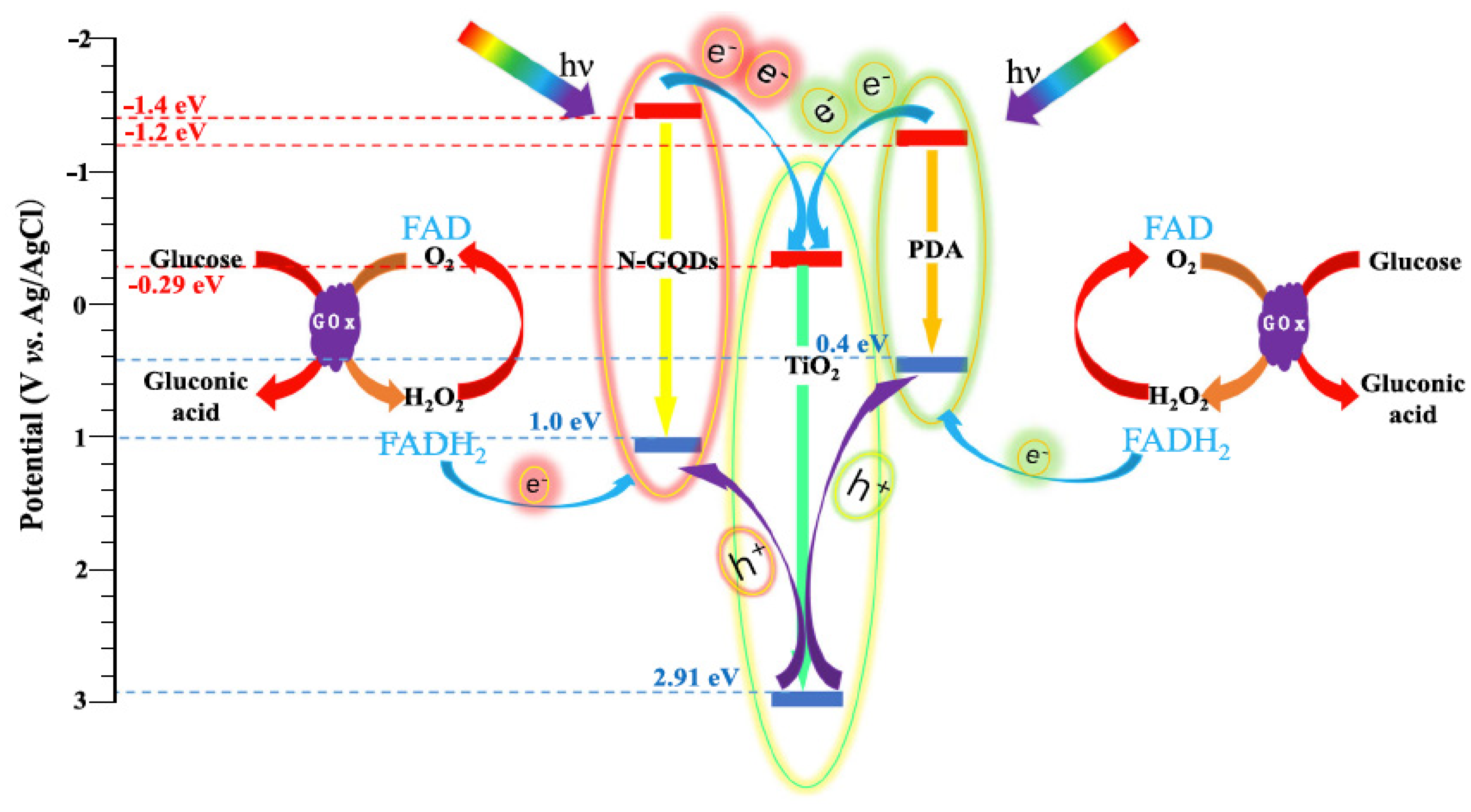
8.4. TiO2-GQDs as Photoelectrochemical Sensors

The increasing cancer rates, cardiovascular diseases, neurodegenerative disorders, autoimmune diseases, and a plethora of infections across the globe necessitate the development of sensitive and accurate detection methods. Photoelectrochemical (PEC) technology, a combination of light and electrochemistry, has received increasing attention in the field of sensing due to its simple structure, rapid response, low background current, and high selectivity [150,151]. To date, many semiconductor nanomaterials, such as CdS, CdSe, ZnO, and TiO2, have been used to construct PEC sensors [152,153,154]. Among these semiconductors, TiO2 nanostructures have been extensively investigated as significant photoelectrochemical materials due to their multitudinous properties, such as excellent photoelectric effect, light corrosion resistance, nontoxicity, availability, and low cost [155]. However, the application of TiO2 remains limited, as it is active only under ultraviolet (UV) light and most of the biological samples may become damaged by UV light in the experimental process. Moreover, TiO2′s high speed of recombination and relatively poor surface bioactive environment reduce the photoelectric effect, affecting the overall efficiency of the device [156]. Hence, in order to overcome these problems, various nanomaterials, especially carbonaceous materials such as graphene, carbon nanotube, and graphene quantum dots, have been coupled with TiO2 nanomaterials to improve their visible-light absorption and other PEC properties [64]. When GQDs are coupled with TiO2 nanomaterials, the composite materials exhibit enhanced PEC properties. These could be due to the following three reasons: efficient h+/e pair separation, extension of light absorption to the visible region, and efficient absorption of light. To date, TiO2-GQD nanocomposites have been successfully used as PEC sensors for the detection of glucose and dopamine biomolecules. Their mechanism of sensing is explained in brief below.
Ahmadi et al. fabricated TiO2/Ceria/GQD nanocomposites and used them as a PEC sensor for the detection of dopamine (DA) [157]. Due to the synergic effect of the TiO2/Ceria/GQD composites, an outstanding photocurrent response was observed with a low detection limit of 22 nM DA and sensitivity of 13.8 mA/mM (DA), in a wider range of 0.3–750 μM DA. The PEC electron transfer mechanism at (TiO2/Ceria/GQD)/(glass calomel electrode (GCE)) in the presence of DA is schematically presented in Figure 32. DA can be excited to DA+◦ under visible light irradiation, and the excited electrons of DA can be transferred to the (TiO2/Ceria/GQD) nanocomposite by two routes [158]. In the first route (1), DA binds to TiO2 planes via its -OH functional groups in the special geometrical condition, accelerates electron transfer, and leads to an increased number of charge carriers [159]. In the second route (2), DA acts as an electron donor, occupies the holes of the (TiO2/Ceria/GQD) nanocomposite valence band, and prevents the recombination of photoexcited electron-hole pairs. The electrons of DA and photoexcited electrons in nanocomposites are also transferred to the counter electrode and the recorded photocurrent by modified electrodes in the presence of DA is amplified compared to the unmodified electrode. This obtained PEC response was further compared with the electrochemical (EC) response, which was observed to be 0.22 μM DA as the detection limit and sensitivity of 4.9 mA/mM (DA), with a range of 1–500 μM DA. As can be observed from the results, the PEC sensor showed better performance in terms of detection speed, figure of merits, and stability of the electrodes. Moreover, the authors reported that the PEC method had potential for miniaturization that could be beneficial for use in portable devices for in-field monitoring of DA, due to its high sensitivity (2.8 times higher), low background signal for DA, low cost, and simple preparation. This research opens up a new avenue for the application of TiO2-GQD-based nanocomposites in the field of PEC sensing and monitoring.
Similarly, a GQD-TiO2 sensor for dopamine detection was proposed by Yan et al., where GQDs were decorated with TiO2 nanoparticles through physical adsorption [160]. Under visible-light irradiation, these nanocomposites revealed enhanced PEC signal amplification, i.e., it increased almost 12 times and 30 times when compared to GCE/TiO2 and GCE/GQDs, respectively. This is attributed to the synergistic amplification between TiO2 NPs and GQDs. Further, these nanocomposites are observed to be sensitive and selective for the detection of dopamine as the photocurrent of these nanocomposites is elevated with an increase in DA concentrations from 0.02 to 105 µM. The PEC response is observed to be linear, with a low detection limit of 6.7 nM.
All these discoveries showed that GQD-TiO2 nanocomposites exhibited great potential in PEC applications. The proposed GQD-TiO2 nanocomposites were highly photosensitive and they could provide a new platform for designing a variety of PEC devices.
Considering the sensitivity and selectivity of TiO2-GQD nanocomposites in detecting dopamine molecules, Yang et al. developed an ultrasensitive dual-electron acceptor PEC sensor by modifying the TiO2 nanotubes (NTs) with polydopamine (PDA) and amino-functionalized graphene quantum dots (N-GQDs)/GOx [76]. PDA is grown on the top of the TiO2 NTs by the electropolymerization, and N-GQDs are loaded into the TiO2 NT core by a microwave-assisted method. The PEC mechanism of this sensor for glucose detection is shown in Figure 33. The conduction band (CB) and valence band (VB) edges of anatase TiO2 are located at −0.29 and 2.91 V versus Ag/AgCl, respectively. The lowest unoccupied molecular orbital and highest occupied molecular orbital of PDA are located at −1.2 and 0.4 eV [161]. The CB and VB edges of N-GQDs are located at −1.4 and 1.0 eV [162]. In the tandem heterojunction, the photogenerated electrons in the CB were transferred from PDA and N-GQDs to TiO2, and the photogenerated holes in the VB transfer in the opposite direction. The enrichment of the holes in the two sites allows the sensor to have two electron acceptors, thereby increasing the response sensitivity to glucose. The TiO2 NTs/PDA/N-GQD dual-electron-acceptor biosensor exhibited a highly enhanced photoelectric response, excellent electron-hole separation efficiency, low detection limit (0.015 mM), wide linear range (0–11 mM), and ultrahigh sensitivity (13.6 l A mM−1 cm-2). The results of electrochemical and PEC examination showed a large increase in the photoelectric response of the TiO2 NT/PDA/NGQD/GOx biosensor. This is attributed to the presence of a dual-electron-acceptor structure that increases electron transport efficiency.

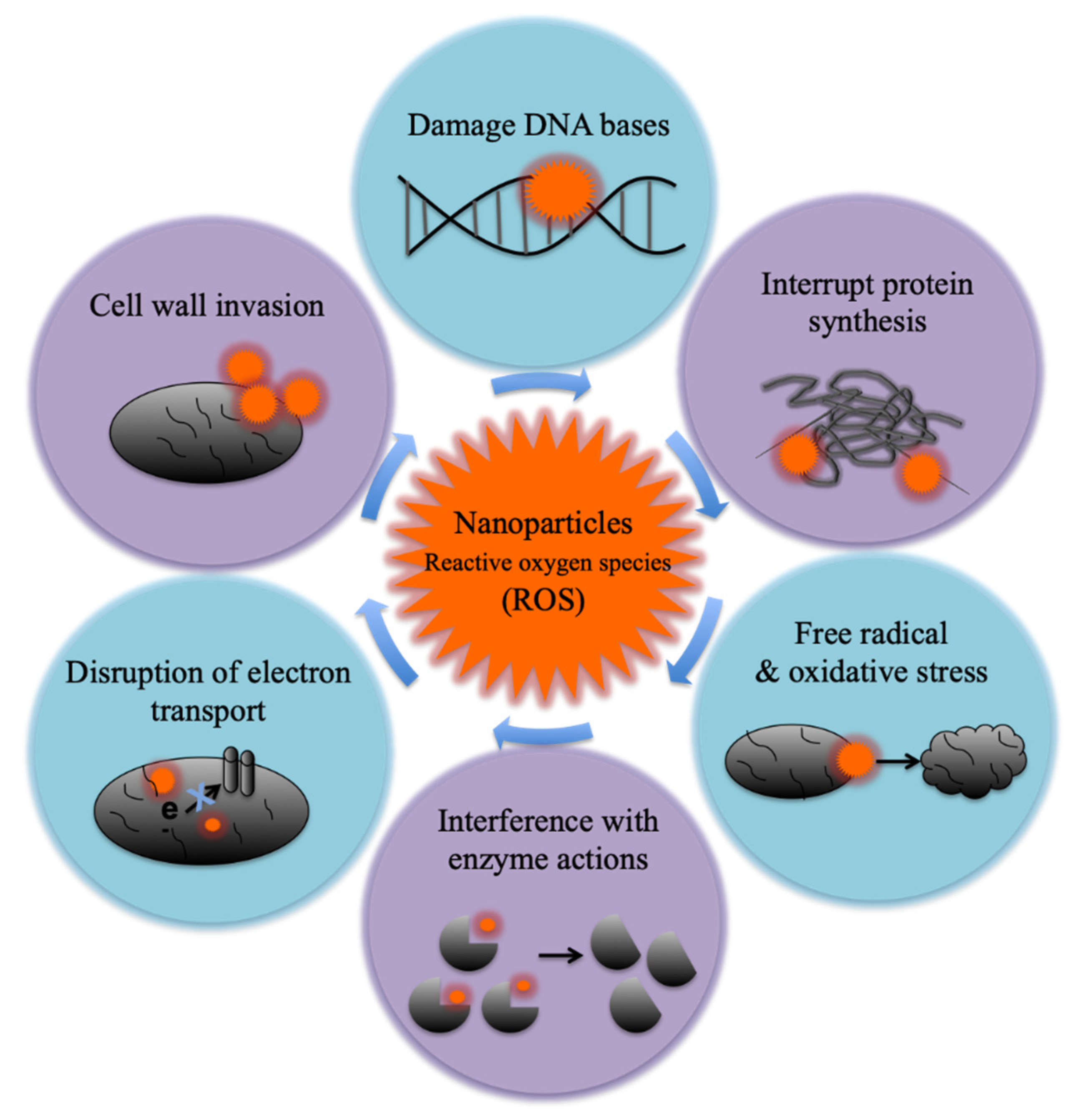
8.5. Antibacterial Activity of TiO2-GQD Nanocomposites

In the last few decades, imprudent use of antibiotics has caused a dramatic increase in drug resistance among single-celled pathogens, which necessitates the development of new strategies for microbial inhibition [163]. Researchers have proposed various alternatives to the conventional treatment of antibiotics, such as antimicrobial peptides, bacteriophages and their lysins, immunomodulators, and predatory microorganisms [35,164]. Though these approaches have potential to fight most infectious diseases, they have some major drawbacks, such as the high cost of implementation and unpredictability of human health risks.
The application of materials science and nanotechnology is relatively simple, affordable, and tailorable in tackling different aspects of microbial infections [165]. Many nanomaterials have been demonstrated to possess inherent antimicrobial properties that are rarely expressed in their bulk form, with the best-known example being silver nanoparticles (Ag NPs) [166]. In recent years, many studies have reported the application of TiO2 nanoparticles in self-cleaning, antibacterial paints, skin treatments, sunscreens, dental applications, and also as a sterilizer and disinfectant. The major advantage of TiO2 over other antibacterial nanoparticles is its broad spectrum of activity against microorganisms including Gram-negative and positive-bacteria and fungi, which is of particular importance for multiple-drug-resistant strains [39,167].
Although several TiO2 nanomaterials with antimicrobial capabilities have been reported, they exhibit poor activity in the visible light region due to the large bandgap (i.e., 3.2 eV) [168]. Moreover, the exploitation of TiO2 nanomaterials in actual clinical practice is currently very limited due to their lower bactericidal efficiency [169]. Hence, some new approaches have been reported where TiO2 has been doped with nanocarbons, exhibiting higher antibacterial activities in the visible light region [31,32]. Nanocarbons such as single-walled and multi-walled carbon nanotubes (SW-MWCNT), graphene sheets, graphene oxide, and especially graphene quantum dots have attracted more attention as antimicrobial agents due to their lower cost and cytotoxicity [170]. Considering these aspects, the combination of TiO2 and GQD nanoparticles is a promising approach to obtain photocatalyst with good antibacterial activity in visible light.
The basic mechanisms behind the antimicrobial activity of nanoparticles are shown in Figure 34. This includes the photoactivation of the semiconductor and formation of superoxide radicals causing cellular oxidative stress followed by bacterial cell death [171]. Several methods are followed to evaluate the antimicrobial property of photocatalytic materials. Different studies have used different experimental conditions, which prevents accurate comparison of test results among these studies. However, the general methods used are suspension-based methods. In these methods, a continuous or batch reactor system containing an aqueous suspension of nanoparticles is inoculated with a test microbe and illuminated with a light source of a suitable wavelength. Samples of the treated suspensions are then collected at specified time intervals to enumerate surviving microbial populations [172]. It was reported that the experimental conditions (such as bacterial cell harvesting conditions, volume of suspension, stirring, and the intensity of light, and so on) as well as characteristics of NPs (such as synthesis method, size, crystal structure, surface area, and surface charge), and the nature of test microorganisms (Gram-positive, Gram-negative, spore formers, nonspore formers) have a significant effect on the photocatalytic disinfection efficiency [173,174].
Biswas et al. synthesized surface-disordered rutile TiO2 nanoparticles as the defects in nanostructured semiconductors may introduce a greater number of charge carriers, enhancing the overall photocatalytic efficiency [73]. These TiO2 nanoparticles are further coupled with GQD nanoparticles by a hydrothermal method. The bactericidal effect of these nanomaterials was measured using non-pathogenic strains of Escherichia coli (E. coli) (NCIM 2931), Pseudomonas aeruginosa (P. aeruginosa) (NCIM 5029), and Staphylococcus aureus (S. aureus) (NCIM 5021) cultures in the dark, under UV illumination, and in sunlight. The MIC values were measured for all of these bacterial strains in the dark and are given in Table 5. The results indicated that the TiO2-GQD nanocomposites showed lower MIC values as compared to TiO2 and GQD alone. The biofilm (of E. coli) disruption capacity of these catalysts was tested in the dark and under UV light illumination, which showed 100% disruption for composites, while TiO2 and GQD showed 86% and 61%, respectively. Further, DCF (dichlorofluorescein) assay was performed to calculate the amount of reactive oxygen species (ROS) generated by TiO2 and TiO2-GQD nanocomposites in the presence of solar illumination. In the presence of ROS, the DCF was converted to its ester form, H2- DCF, which is fluorescent. Thus, the emission of DCF is proportional to the amount of ROS formed. The results showed significant enhancement in the formation of ROS for the TiO2-GQD nanocomposites under sunlight irradiation. This enhancement could be attributed to the introduction of GQDs to TiO2 nanoparticles, which increases the VBM (valence band maxima) of TiO2 nanoparticles, which, in turn, increases its solar energy harvesting efficiency as well as the antibacterial activity of the composites.
H. Teymourinia et al. have prepared TiO2, TiO2-GQD, Sb2S3-GQD, and TiO2-Sb2S3-GQD nanocomposites by green (hydrothermal) synthesis and compared their antibacterial activity under visible light irradiation [175]. E. coli and S. aureus were used as model microorganisms in order to measure the minimal inhibitory concentration (MIC) of these nanostructures. The experimental results showed that the TiO2-Sb2S3-GQD nanocomposites exhibit significantly lower MIC values than the TiO2, TiO2-GQD and Sb2S3-GQD nanocomposites. The higher bactericidal activity is attributed to the greater number of electrons and holes produced by GQD nanoparticles.

9. Future Scope

TiO2-GQD nanocomposites have potential not only in photocatalysis and degradation of pollutants, but also in other applications, such as hydrogen production from water splitting and DSSC. In addition, GQD-based composites can be used for many biomedical applications, such as drug delivery, biosensing, tissue-engineering, and as contrasting agents in bioimaging [176,177,178]. However, TiO2-GQDs are still in the early stage of development. Challenges still remain in using these nanocomposites in a continuous mode. A few challenges faced in the field are discussed below.
1. High-quality production of GQDs
Engineering applications demand the massive production of high-quality GQDs with controllable layers, sizes, and compositions by a rapid, economic, and energy-efficient process. However, it is very difficult to produce high-quality and crystalline GQDs that possess very high electrical and thermal conductivities by mass production methods. Another issue of concern for the synthesis of GQDs involves the use of toxic chemicals. The use of toxic chemicals to synthesize GQDs usually results in the generation of hazardous waste and poisonous gases. At present, the hydrothermal process using GO as a starting material to obtain GQDs is the most environmentally friendly approach, but it is not an economical method for the mass production of GQDs. Strong acidic treatment to graphite is the method which can achieve mass production, but it involves the use of hazardous chemicals. In order to surmount these barriers, new synthesis methods must be developed for the large-scale production of low-cost and high-quality GQDs via simple and eco-friendly approaches.
2. Synthesis of TiO2-GQD nanocomposites with desired properties
The properties and functions of TiO2-GQD nanocomposites depend strongly on their microstructures. Therefore, synthesis methods must be designed to obtain nanocomposites of higher quality, more uniform morphology, and better photocatalytic properties. There are already synthesis routes, namely solution mixing, sol–gel, hydrothermal/solvothermal, self-assembly, microwave irradiation, and electrochemical deposition, for the production of graphene–metal/metal oxide nanocomposites. However, there are a few key challenges still remaining related to the synthesis methods, where scalable, economically sustainable, high-quality, and reproducible production of TiO2-GQD nanocomposites is desired.
3. Immobilization of these nanocomposites for reusability
In the photocatalysis process, photocatalyst (TiO2-GQD nanocomposites) powders are usually dispersed in wastewater directly. Although this process enables full contact and high degradation efficiency of the catalyst’s particles on the pollutants, the recovery of the catalyst powder represents an additional problem. It is very difficult to recover these catalyst particles completely from the treated water, especially for nanometer particles. In fact, incomplete recovery of the catalyst particles would lead to secondary pollution for water treatment. To overcome this, nanocomposites should be immobilized by using appropriate substrates such as polymers, glass fibers, or aluminum plates, or by combining them with magnetic materials or chemical or biological coagulants. Unfortunately, the efficiency of the photocatalyst is reduced to a large extent as a result of immobilization. Hence, immobilization strategies for nanophotocatalysts which are eco-friendly, cost-effective, and allow reusability must be developed.
4. Multicomponent TiO2-GQD nanocomposites
Fifth, TiO2-GQD nanocomposites contain only two components. However, composites containing more than two components should also be designed to achieve higher performance based on the synergetic effects of multicomponents, e.g., TiO2–graphene–carbon nanotube composites could be used as efficient anode materials in Li-ion batteries [179], TiO2–graphene–polyaniline could be used as a bioanode in microbial fuel cells [180], and TiO2–graphene oxide–Ag3PO4 composites have superior photocatalytic and antibacterial properties [181]. Hence, the fabrication of multicomponent composites focusing on different subfunctional regimes, such as mechanical and collective functional applications including energy, electronics biomedical, membranes, and sensors, should be encouraged. Finally, the applications of composites are at their initial stages. They need to be studied systematically in terms of both theoretical and experimental aspects.

Author Contributions

F.E. perceived the original idea and design of the presented data. A.B. wrote the manuscript with support from S.C., F.E. and S.C. provided critical feedback and helped shaping the manuscript. All authors have read and agreed to the published version of the manuscript.

Funding

This research received no external funding.

Data Availability Statement

The data presented in this review are from published sources.

Conflicts of Interest

The authors declare no conflict of interest.

References

  1. Naseem, S.; Gevers, B.R.; Labuschagné, F.J.W.J.; Leuteritz, A. Preparation of Photoactive Transition-Metal Layered Double Hydroxides (LDH) to Replace Dye-Sensitized Materials in Solar Cells. Materials 2020, 13, 4384. [Google Scholar] [CrossRef]
  2. Tallman, T.N.; Smyl, D.J. Structural health and condition monitoring via electrical impedance tomography in self-sensing materials: A review. Smart Mater. Struct. 2020, 29, 123001. [Google Scholar] [CrossRef]
  3. Levi, D.S.; Kusnezov, N.; Carman, G.P. Smart materials applications for pediatric cardiovascular devices. Pediatr. Res. 2008, 63, 552–558. [Google Scholar] [CrossRef] [Green Version]
  4. Ali, A.; Andriyana, A. Properties of multifunctional composite materials based on nanomaterials: A review. RSC Adv. 2020, 10, 16390–16403. [Google Scholar] [CrossRef]
  5. Gibson, R.F. A review of recent research on mechanics of multifunctional composite materials and structures. Compos. Struct. 2010, 92, 2793–2810. [Google Scholar] [CrossRef]
  6. Narayana, K.J.; Gupta Burela, R. A review of recent research on multifunctional composite materials and structures with their applications. Mater. Today Proc. 2018, 5, 5580–5590. [Google Scholar] [CrossRef]
  7. Wu, X.; Wang, C.; Wei, Y.; Xiong, J. Multifunctional photocatalysts of Pt-decorated 3DOM perovskite-type SrTiO3 with enhanced CO2 adsorption and photoelectron enrichment for selective CO2 reduction with H2O to CH4. J. Catal. 2019, 377, 309–321. [Google Scholar] [CrossRef]
  8. Zhou, H.; Qu, Y.; Zeid, T.; Duan, X. Towards highly efficient photocatalysts using semiconductor nanoarchitectures. Energy Environ. Sci. 2012, 5, 6732–6743. [Google Scholar] [CrossRef]
  9. Pakdel, E.; Wang, J.; Kashi, S.; Sun, L.; Wang, X. Advances in photocatalytic self-cleaning, superhydrophobic and electromagnetic interference shielding textile treatments. Adv. Colloid Interface Sci. 2020, 277, 102116. [Google Scholar] [CrossRef] [PubMed]
  10. Kim, D.; Shin, K.; Kwon, S.G.; Hyeon, T. Synthesis and Biomedical Applications of Multifunctional Nanoparticles. Adv. Mater. 2018, 30, e1802309. [Google Scholar] [CrossRef] [PubMed]
  11. Kim, D.; Whang, D.R.; Park, S.Y. Self-Healing of Molecular Catalyst and Photosensitizer on Metal-Organic Framework: Robust Molecular System for Photocatalytic H2 Evolution from Water. J. Am. Chem. Soc. 2016, 138, 8698–8701. [Google Scholar] [CrossRef] [PubMed]
  12. Zhang, M.; Wu, F.; Wang, W.; Shen, J.; Zhou, N.; Wu, C. Multifunctional Nanocomposites for Targeted, Photothermal, and Chemotherapy. Chem. Mater. 2019, 31, 1847–1859. [Google Scholar] [CrossRef]
  13. Nam, N.H.; Luong, N.H. Chapter 7—Nanoparticles: Synthesis and applications. In Materials for Biomedical Engineering; Grumezescu, V., Grumezescu, A.M., Eds.; Elsevier: Amsterdam, The Netherlands, 2019; pp. 211–240. [Google Scholar]
  14. Vijayan, P.P.; Puglia, D. Biomimetic multifunctional materials: A review. Emerg. Mater. 2019, 2, 391–415. [Google Scholar] [CrossRef]
  15. Lendlein, A.; Trask, R.S. Multifunctional materials: Concepts, function-structure relationships, knowledge-based design, translational materials research. Multifunct. Mater. 2018, 1, 010201. [Google Scholar] [CrossRef]
  16. Do, H.H.; Nguyen, D.L.T.; Nguyen, N.C.; Le, T.H.; Nguyen, T.P.; Trinh, Q.T.; Ahn, S.H.; Vo, D.V.N.; Kim, S.Y.; Le, Q.V. Recent progress in TiO2-based photocatalysts for hydrogen evolution reaction: A review. Arab. J. Chem. 2020, 13, 3653–3671. [Google Scholar] [CrossRef]
  17. Noman, M.T.; Ashraf, M.A.; Ali, A. Synthesis and applications of nano-TiO2: A review. Environ. Sci. Pollut. Res. Int. 2019, 26, 3262–3291. [Google Scholar] [CrossRef] [PubMed]
  18. Hernández-Alonso, M.D.; Fresno, F.; Suárez, S.; Coronado, J.M. Development of alternative photocatalysts to TiO2: Challenges and opportunities. Energy Environ. Sci. 2009, 2, 1231–1257. [Google Scholar] [CrossRef]
  19. Dong, H.; Zeng, G.; Tang, L.; Fan, C.; Zhang, C.; He, X.; He, Y. An overview on limitations of TiO2-based particles for photocatalytic degradation of organic pollutants and the corresponding countermeasures. Water Res. 2015, 79, 128–146. [Google Scholar] [CrossRef]
  20. Kumar, S.G.; Devi, L.G. Review on modified TiO2 photocatalysis under UV/visible light: Selected results and related mechanisms on interfacial charge carrier transfer dynamics. J. Phys. Chem. A 2011, 115, 13211–13241. [Google Scholar] [CrossRef] [PubMed]
  21. Singh, V.; Joung, D.; Zhai, L.; Das, S.; Khondaker, S.I.; Seal, S. Graphene based materials: Past, present and future. Prog. Mater Sci. 2011, 56, 1178–1271. [Google Scholar] [CrossRef]
  22. Skoda, M.; Dudek, I.; Jarosz, A.; Szukiewicz, D. Graphene: One Material, Many Possibilities—Application Difficulties in Biological Systems. J. Nanomater. 2014, 2014, 890246. [Google Scholar] [CrossRef]
  23. Ravi Kumar, Y.; Deshmukh, K.; Sadasivuni, K.K.; Khadheer Pasha, S.K. Graphene quantum dot based materials for sensing, bio-imaging and energy storage applications: A review. RSC Adv. 2020, 10, 23861–23898. [Google Scholar] [CrossRef]
  24. Sun, H.; Wu, L.; Wei, W.; Qu, X. Recent advances in graphene quantum dots for sensing. Mater. Today 2013, 16, 433–442. [Google Scholar] [CrossRef]
  25. Kellici, S.; Acord, J.; Power, N.P.; Morgan, D.J.; Coppo, P.; Heil, T.; Saha, B. Rapid synthesis of graphene quantum dots using a continuous hydrothermal flow synthesis approach. RSC Adv. 2017, 7, 14716–14720. [Google Scholar] [CrossRef] [Green Version]
  26. Wang, S.; Chen, Z.-G.; Cole, I.; Li, Q. Structural evolution of graphene quantum dots during thermal decomposition of citric acid and the corresponding photoluminescence. Carbon N. Y. 2015, 82, 304–313. [Google Scholar] [CrossRef] [Green Version]
  27. Wang, D.; Saleh, N.B.; Sun, W.; Park, C.M.; Shen, C.; Aich, N.; Peijnenburg, W.J.G.M.; Zhang, W.; Jin, Y.; Su, C. Next-Generation Multifunctional Carbon-Metal Nanohybrids for Energy and Environmental Applications. Environ. Sci. Technol. 2019, 53, 7265–7287. [Google Scholar] [CrossRef] [PubMed]
  28. Kumaravel, V.; Mathew, S.; Bartlett, J.; Pillai, S.C. Photocatalytic hydrogen production using metal doped TiO2: A review of recent advances. Appl. Catal. B 2019, 244, 1021–1064. [Google Scholar] [CrossRef]
  29. Zhou, Y.; Yang, S.; Fan, D.; Reilly, J.; Zhang, H.; Yao, W.; Huang, J. Carbon Quantum Dot/TiO2 Nanohybrids: Efficient Photocatalysts for Hydrogen Generation via Intimate Contact and Efficient Charge Separation. ACS Appl. Nano Mater. 2019, 2, 1027–1032. [Google Scholar] [CrossRef]
  30. Siwińska-Stefańska, K.; Fluder, M.; Tylus, W.; Jesionowski, T. Investigation of amino-grafted TiO2/reduced graphene oxide hybrids as a novel photocatalyst used for decomposition of selected organic dyes. J. Environ. Manag. 2018, 212, 395–404. [Google Scholar] [CrossRef] [PubMed]
  31. Etacheri, V.; Michlits, G.; Seery, M.K.; Hinder, S.J.; Pillai, S.C. A highly efficient TiO(2-x)C(x) nano-heterojunction photocatalyst for visible light induced antibacterial applications. ACS Appl. Mater. Interfaces 2013, 5, 1663–1672. [Google Scholar] [CrossRef] [PubMed] [Green Version]
  32. Cao, B.; Cao, S.; Dong, P.; Gao, J.; Wang, J. High antibacterial activity of ultrafine TiO2/graphene sheets nanocomposites under visible light irradiation. Mater. Lett. 2013, 93, 349–352. [Google Scholar] [CrossRef]
  33. Zheng, L.; Su, H.; Zhang, J.; Walekar, L.S.; Molamahmood, H.V.; Zhou, B.; Long, M.; Hu, Y.H. Highly selective photocatalytic production of H2O2 on sulfur and nitrogen co-doped graphene quantum dots tuned TiO2. Appl. Catal. B 2018, 239, 475–484. [Google Scholar] [CrossRef]
  34. Long, R.; Casanova, D.; Fang, W.-H.; Prezhdo, O.V. Donor-Acceptor Interaction Determines the Mechanism of Photoinduced Electron Injection from Graphene Quantum Dots into TiO2: π-Stacking Supersedes Covalent Bonding. J. Am. Chem. Soc. 2017, 139, 2619–2629. [Google Scholar] [CrossRef] [PubMed]
  35. Wang, S.; Cole, I.S.; Li, Q. Quantum-confined bandgap narrowing of TiO2 nanoparticles by graphene quantum dots for visible-light-driven applications. Chem. Commun. 2016, 52, 9208–9211. [Google Scholar] [CrossRef]
  36. Huo, P.; Shi, X.; Zhang, W.; Kumar, P.; Liu, B. An overview on the incorporation of graphene quantum dots on TiO 2 for enhanced performances. J. Mater. Sci. 2021, 56, 6031–6051. [Google Scholar] [CrossRef]
  37. Fujishima, A.; Honda, K. Electrochemical photolysis of water at a semiconductor electrode. Nature 1972, 238, 37–38. [Google Scholar] [CrossRef]
  38. Guo, Q.; Zhou, C.; Ma, Z.; Yang, X. Fundamentals of TiO2 Photocatalysis: Concepts, Mechanisms, and Challenges. Adv. Mater. 2019, 31, e1901997. [Google Scholar] [CrossRef]
  39. Kubacka, A.; Diez, M.S.; Rojo, D.; Bargiela, R.; Ciordia, S.; Zapico, I.; Albar, J.P.; Santos, V.A.P.M.D.; Garcia, M.F.; Ferrer, M. Understanding the antimicrobial mechanism of TiO2-based nanocomposite films in a pathogenic bacterium. Sci. Rep. 2014, 4, 4134. [Google Scholar] [CrossRef] [PubMed] [Green Version]
  40. Ali, I.; Suhail, M.; Alothman, Z.A.; Alwarthan, A. Recent advances in syntheses, properties and applications of TiO2 nanostructures. RSC Adv. 2018, 8, 30125–30147. [Google Scholar] [CrossRef] [Green Version]
  41. Jhang, J.-H.; Chang, S.-J.; Pedaballi, S.; Li, C.-C. A new porous structure with dispersed nano-TiO2 in a three-dimensional carbon skeleton for achieving high photocatalytic activity. Microporous Mesoporous Mater. 2019, 276, 62–67. [Google Scholar] [CrossRef]
  42. Ge, M.; Cai, J.; Locozzia, J.; Cao, C.; Huang, J.; Zhang, X.; Shen, J.; Wang, S.; Zhang, K.Q.; Lai, Y.Z. A review of TiO2 nanostructured catalysts for sustainable H2 generation. Int. J. Hydrogen Energy 2017, 42, 8418–8449. [Google Scholar] [CrossRef]
  43. Ghosh, M.; Liu, J.; Chuang, S.S.C.; Jana, S.C. Fabrication of hierarchical V2 O5 nanorods on TiO2 nanofibers and their enhanced photocatalytic activity under visible light. ChemCatChem 2018, 10, 3305–3318. [Google Scholar] [CrossRef]
  44. Zheng, P.; Zhou, W.; Wang, Y.; Ren, D.; Zhao, J.; Guo, S. N-doped graphene-wrapped TiO2 nanotubes with stable surface Ti3+ for visible-light photocatalysis. Appl. Surf. Sci. 2020, 512, 144549. [Google Scholar] [CrossRef]
  45. Morales-García, Á.; Macià Escatllar, A.; Illas, F.; Bromley, S.T. Understanding the interplay between size, morphology and energy gap in photoactive TiO2 nanoparticles. Nanoscale 2019, 11, 9032–9041. [Google Scholar] [CrossRef]
  46. Khan, R.; Javed, S.; Islam, M. Hierarchical Nanostructures of Titanium Dioxide: Synthesis and Applications. In Titanium Dioxide; Yang, D., Ed.; IntechOpen: London, UK, 2018. [Google Scholar]
  47. Cargnello, M.; Gordon, T.R.; Murray, C.B. Solution-phase synthesis of titanium dioxide nanoparticles and nanocrystals. Chem. Rev. 2014, 114, 9319–9345. [Google Scholar] [CrossRef] [PubMed]
  48. Chen, X.; Mao, S.S. Titanium dioxide nanomaterials: Synthesis, properties, modifications, and applications. Chem. Rev. 2007, 107, 2891–2959. [Google Scholar] [CrossRef] [PubMed]
  49. Negrín-Montecelo, Y.; Anta, M.T.; Caba, L.M.; Lorenzo, M.P.; Salgueirino, V.; Durate, M.A.C.; Hermo, M.C. Titanate Nanowires as One-Dimensional Hot Spot Generators for Broadband Au-TiO2 Photocatalysis. Nanomaterials 2019, 9, 990. [Google Scholar] [CrossRef] [PubMed] [Green Version]
  50. Zhang, W.; Xie, Y.; Xiong, D.; Zeng, X.; Li, Z.; Wamg, M.; Cheng, Y.B.; Chen, W.; Yan, K.; Yang, S. TiO2 nanorods: A facile size- and shape-tunable synthesis and effective improvement of charge collection kinetics for dye-sensitized solar cells. ACS Appl. Mater. Interfaces 2014, 6, 9698–9704. [Google Scholar] [CrossRef] [PubMed]
  51. Hsu, H.-J.; Li, C.-C. TiO2-based microsphere with large pores to improve the electrochemical performance of Li-ion anodes. Ceram. Int. 2021. [Google Scholar] [CrossRef]
  52. Tang, X.; Chu, W.; Qian, J.; Lin, J.; Cao, G. Photocatalysis: Low temperature synthesis of large-size anatase TiO2 nanosheets with enhanced photocatalytic activities (small 48/2017). Small 2017, 13, 1770255. [Google Scholar] [CrossRef] [Green Version]
  53. Ghosh, M.; Lohrasbi, M.; Chuang, S.S.C.; Jana, S.C. Mesoporous titanium dioxide nanofibers with a significantly enhanced photocatalytic activity. ChemCatChem 2016, 8, 2525–2535. [Google Scholar] [CrossRef]
  54. Daghrir, R.; Drogui, P.; Robert, D. Modified TiO2 For Environmental Photocatalytic Applications: A Review. Ind. Eng. Chem. Res. 2013, 52, 3581–3599. [Google Scholar] [CrossRef]
  55. Luo, J.; Zhang, S.; Sun, M.; Yang, L.; Luo, S.; Crittenden, J.C. A Critical Review on Energy Conversion and Environmental Remediation of Photocatalysts with Remodeling Crystal Lattice, Surface, and Interface. ACS Nano 2019, 13, 9811–9840. [Google Scholar] [CrossRef] [PubMed]
  56. Chung, S.; Revia, R.A.; Zhang, M. Graphene Quantum Dots and Their Applications in Bioimaging, Biosensing, and Therapy. Adv. Mater. 2019, e1904362. [Google Scholar] [CrossRef] [PubMed]
  57. Tian, P.; Tang, L.; Teng, K.S.; Lau, S.P. Graphene quantum dots from chemistry to applications. Mater. Today Chem. 2018, 10, 221–258. [Google Scholar] [CrossRef]
  58. Tajik, S.; Dourandish, Z.; Zhang, K.; Beitollahi, H.; Le, Q.V.; Jang, H.W.; Shokouhimehr, M. Carbon and graphene quantum dots: A review on syntheses, characterization, biological and sensing applications for neurotransmitter determination. RSC Adv. 2020, 10, 15406–15429. [Google Scholar] [CrossRef] [Green Version]
  59. Facure, M.H.M.; Schneider, R.; Mercante, L.A.; Correa, D.S. A review on graphene quantum dots and their nanocomposites: From laboratory synthesis towards agricultural and environmental applications. Environ. Sci. Nano 2020. [Google Scholar] [CrossRef]
  60. Prabhu, S.A.; Kavithayeni, V.; Suganthy, R.; Geetha, K. Graphene quantum dots synthesis and energy application: A review. Carbon Lett. 2020. [Google Scholar] [CrossRef]
  61. Belchi, R.; Habert, A.; Foy, E.; Gheno, A.; Vedraine, S.; Antony, R.; Ratier, B.; Boucle, J.; Boime, N.H. One-Step Synthesis of TiO2/Graphene Nanocomposites by Laser Pyrolysis with Well-Controlled Properties and Application in Perovskite Solar Cells. ACS Omega 2019, 4, 11906–11913. [Google Scholar] [CrossRef] [Green Version]
  62. Ton, N.N.T.; Dao, A.T.N.; Kato, K.; Ikenaga, T.; Trinh, D.X.; Taniike, T. One-pot synthesis of TiO2/graphene nanocomposites for excellent visible light photocatalysis based on chemical exfoliation method. Carbon N. Y. 2018, 133, 109–117. [Google Scholar] [CrossRef]
  63. Chen, W.; Lv, G.; Hu, W.; Li, D.; Chen, S.; Dai, Z. Synthesis and applications of graphene quantum dots: A review. Nanotechnol. Rev. 2018, 7, 157–185. [Google Scholar] [CrossRef]
  64. Li, M.; Chen, T.; Gooding, J.J.; Liu, J. Review of Carbon and Graphene Quantum Dots for Sensing. ACS Sens. 2019, 4, 1732–1748. [Google Scholar] [CrossRef]
  65. Chhabra, V.A.; Kaur, R.; Kumar, N.; Rajesh, C.; Kim, K.H. Synthesis and spectroscopic studies of functionalized graphene quantum dots with diverse fluorescence characteristics. RSC Adv. 2018, 8, 11446–11454. [Google Scholar] [CrossRef] [Green Version]
  66. Mansuriya, B.D.; Altintas, Z. Applications of Graphene Quantum Dots in Biomedical Sensors. Sensors 2020, 20, 1072. [Google Scholar] [CrossRef] [Green Version]
  67. Sclafani, A.; Palmisano, L.; Schiavello, M. Influence of the preparation methods of titanium dioxide on the photocatalytic degradation of phenol in aqueous dispersion. J. Phys. Chem. 1990, 94, 829–832. [Google Scholar] [CrossRef]
  68. Pathak, P.; Israel, L.H.; Pereira, E.J.M.; Subramanian, V.R. Effects of Carbon Allotrope Interface on the Photoactivity of Rutile One-Dimensional (1D) TiO2 Coated with Anatase TiO2 and Sensitized with CdS Nanocrystals. ACS Appl. Mater. Interfaces 2016, 8, 13400–13409. [Google Scholar] [CrossRef]
  69. Tayel, A.; Ramadan, A.; El Seoud, O. Titanium Dioxide/Graphene and Titanium Dioxide/Graphene Oxide Nanocomposites: Synthesis, Characterization and Photocatalytic Applications for Water Decontamination. Catalysts 2018, 8, 491. [Google Scholar] [CrossRef] [Green Version]
  70. Liu, N.; Chen, X.; Zhang, J.; Schwank, J.W. A review on TiO2-based nanotubes synthesized via hydrothermal method: Formation mechanism, structure modification, and photocatalytic applications. Catal. Today 2014, 225, 34–51. [Google Scholar] [CrossRef]
  71. Pan, D.; Jiao, J.; Li, Z.; Guo, Y.; Feng, C.; Liu, Y.; Wang, L.; Wu, M. Efficient Separation of Electron–Hole Pairs in Graphene Quantum Dots by TiO2 Heterojunctions for Dye Degradation. ACS Sustain. Chem. Eng. 2015, 3, 2405–2413. [Google Scholar] [CrossRef]
  72. Xie, H.; Hou, C.; Wang, H.; Zhang, Q.; Li, Y. S, N Co-Doped Graphene Quantum Dot/TiO2 Composites for Efficient Photocatalytic Hydrogen Generation. Nanoscale Res. Lett. 2017, 12, 400. [Google Scholar] [CrossRef] [PubMed]
  73. Biswas, A.; Salunke, G.; Khandelwal, P.; Das, R.; Poddar, P. Surface disordered rutile TiO2–graphene quantum dot hybrids: A new multifunctional material with superior photocatalytic and biofilm eradication properties. New J. Chem. 2017, 41, 2642–2657. [Google Scholar] [CrossRef]
  74. Yan, X.; Cui, X.; Li, B.; Li, L.-S. Large, solution-processable graphene quantum dots as light absorbers for photovoltaics. Nano Lett. 2010, 10, 1869–1873. [Google Scholar] [CrossRef] [PubMed]
  75. Falk, G.S.; Borlaf, M.; López-Muñoz, M.J.; Fariñas, J.C.; Moreno, R. Microwave-assisted synthesis of TiO2 nanoparticles: Photocatalytic activity of powders and thin films. J. Nanopart. Res. 2018, 20. [Google Scholar] [CrossRef]
  76. Yang, W.; Xu, W.; Zhang, N.; Lai, X.; Tu, J. TiO2 nanotubes modified with polydopamine and graphene quantum dots as a photochemical biosensor for the ultrasensitive detection of glucose. J. Mater. Sci. 2020, 55. [Google Scholar] [CrossRef]
  77. Athawale, A.; Bokare, A.; Singh, H.; Nguyen, V.-H.; Sharma, A. Synthesis of Ag2O Coated TiO2 Nanoparticles by Sonochemically Activated Methods for Enhanced Photocatalytic Activities. Top. Catal. 2020, 63, 3. [Google Scholar] [CrossRef]
  78. Chinnusamy, S.; Kaur, R.; Bokare, A.; Erogbogbo, F. Incorporation of graphene quantum dots to enhance photocatalytic properties of anatase TiO2. MRS Commun. 2018, 8, 137–144. [Google Scholar] [CrossRef]
  79. Shafaee, M.; Goharshadi, E.K.; Mashreghi, M.; Sadeghinia, M. TiO2 nanoparticles and TiO2@graphene quantum dots nancomposites as effective visible/solar light photocatalysts. J. Photochem. Photobiol. A Chem. 2018, 357, 90–102. [Google Scholar] [CrossRef]
  80. Chan, D.K.L.; Cheung, P.L.; Yu, J.C. A visible-light-driven composite photocatalyst of TiO2 nanotube arrays and graphene quantum dots. Beilstein J. Nanotechnol. 2014, 5, 689–695. [Google Scholar] [CrossRef] [Green Version]
  81. Sun, X.; Li, H.J.; Ou, N.; Lyu, B.; Gui, B.; Tian, S.; Qian, D.; Wang, X.; Yang, J. Visible-Light Driven TiO₂ Photocatalyst Coated with Graphene Quantum Dots of Tunable Nitrogen Doping. Molecules 2019, 24, 344. [Google Scholar] [CrossRef] [Green Version]
  82. Qu, D.; Sun, Z.; Zheng, M.; Li, J.; Zhang, Y.; Zhang, G.; Zhao, H.; Liu, X.; Xie, Z. Three Colors Emission from S,N Co-doped Graphene Quantum Dots for Visible Light H 2 Production and Bioimaging. Adv. Opt. Mater. 2015, 3, 360–367. [Google Scholar] [CrossRef]
  83. Jiang, S.P. A review of wet impregnation—An alternative method for the fabrication of high performance and nano-structured electrodes of solid oxide fuel cells. Mater. Sci. Eng. A 2006, 418, 199–210. [Google Scholar] [CrossRef]
  84. Yu, Y.; Ren, J.; Meng, M. Photocatalytic hydrogen evolution on graphene quantum dots anchored TiO2 nanotubes-array. Int. J. Hydrogen Energy 2013, 38, 12266–12272. [Google Scholar] [CrossRef]
  85. Mohanty, U.S. Electrodeposition: A versatile and inexpensive tool for the synthesis of nanoparticles, nanorods, nanowires, and nanoclusters of metals. J. Appl. Electrochem. 2011, 41, 257–270. [Google Scholar] [CrossRef]
  86. Xu, Z.; Yin, M.; Sun, J.; Ding, G.; Lu, L.; Chang, P.; Chen, X.; Li, D. 3D periodic multiscale TiO₂ architecture: A platform decorated with graphene quantum dots for enhanced photoelectrochemical water splitting. Nanotechnology 2016, 27, 115401. [Google Scholar] [CrossRef] [PubMed]
  87. Sudhagar, P.; Cardona, I.H.; Park, H.; Song, T.; Noh, S.H.; Gimenez, S.; Sero, I.M.; Santiago, F.F.; Bisquert, J.; Terashima, C.; et al. Exploring Graphene Quantum Dots/TiO2 interface in photoelectrochemical reactions: Solar to fuel conversion. Electrochim. Acta 2016, 187, 249–255. [Google Scholar] [CrossRef]
  88. Wenderich, K.; Mul, G. Methods, Mechanism, and Applications of Photodeposition in Photocatalysis: A Review. Chem. Rev. 2016, 116, 14587–14619. [Google Scholar] [CrossRef]
  89. Hao, X.; Jin, Z.; Xu, J.; Min, S.; Lu, G. Functionalization of TiO2 with graphene quantum dots for efficient photocatalytic hydrogen evolution. Superlattices Microstruct. 2016, 94, 237–244. [Google Scholar] [CrossRef]
  90. Hosseini, A.; Içli, K.Ç.; Özenbaş, M.; Erçelebi, Ç. Fabrication and Characterization of Spin-coated TiO2 Films. Energy Procedia 2014, 60, 191–198. [Google Scholar] [CrossRef] [Green Version]
  91. Bayat, A.; Saievar-Iranizad, E. Graphene quantum dots decorated rutile TiO2 nanoflowers for water splitting application. J. Mater. Chem. A Mater. Energy Sustain. 2018, 27, 306–310. [Google Scholar] [CrossRef] [Green Version]
  92. Eslamian, M.; Zabihi, F. Ultrasonic Substrate Vibration-Assisted Drop Casting (SVADC) for the Fabrication of Photovoltaic Solar Cell Arrays and Thin-Film Devices. Nanoscale Res. Lett. 2015, 10, 462. [Google Scholar] [CrossRef] [PubMed] [Green Version]
  93. Gupta, B.K.; Kedawat, G.; Agrawal, Y.; Dwivedi, J.; Dhawan, S.K. A novel strategy to enhance ultraviolet light driven photocatalysis from graphene quantum dots infilled TiO2 nanotube arrays. RSC Adv. 2015, 5, 10623–10631. [Google Scholar] [CrossRef] [Green Version]
  94. Kamarulzaman, N.H.; Salleh, H.; Dagang, A.N.; Ghazali, M.S.M.; Ahmad, Z. Optimization of Titanium Dioxide Layer Fabrication Using Doctor Blade Method in Improving Efficiency of Hybrid Solar Cells. J. Phys. Conf. Ser. 2020, 1535, 012025. [Google Scholar] [CrossRef]
  95. Mustafa, M.N.; Sulaiman, Y. Optimization of titanium dioxide decorated by graphene quantum dot as a light scatterer for enhanced dye-sensitized solar cell performance. J. Electroanal. Chem. 2020, 876, 114516. [Google Scholar] [CrossRef]
  96. Salam, Z.; Vijayakumar, E.; Subramania, A.; Sivasankar, N.; Mallick, S. Graphene quantum dots decorated electrospun TiO2 nanofibers as an effective photoanode for dye sensitized solar cells. Sol. Energy Mater. Sol. Cells 2015, 143, 250–259. [Google Scholar] [CrossRef]
  97. Subramanian, A.; Pan, Z.; Rong, G.; Li, H.; Zhou, L.; Li, W.; Qiu, Y.; Xu, Y.; Hou, Y.; Zheng, Z.; et al. Graphene quantum dot antennas for high efficiency Förster resonance energy transfer based dye-sensitized solar cells. J. Power Sources 2017, 343, 39–46. [Google Scholar] [CrossRef]
  98. Kundu, S.; Sarojinijeeva, P.; Karthick, R.; Anantharaj, G.; Saritha, G.; Bera, R.; Anandan, S.; Patra, A.; Ragupathy, P.; Selvaraj, M.; et al. Enhancing the Efficiency of DSSCs by the Modification of TiO2 Photoanodes using N, F and S, co-doped Graphene Quantum Dots. Electrochim. Acta 2017, 242, 337–343. [Google Scholar] [CrossRef]
  99. Kumar, D.K.; Sarojinijeeva, P.; Karthick, R.; Ananthraj, G.; Saritha, G.; Bera, R.; Patra, A.; Ragupathy, P.; Selvaraj, M.; Jeyakumar, D.; et al. Low-temperature titania-graphene quantum dots paste for flexible dye-sensitised solar cell applications. Electrochim. Acta 2019, 305, 278–284. [Google Scholar] [CrossRef] [Green Version]
  100. Shen, D.; Zhang, W.; Xie, F.; Li, Y.; Abate, A.; Wei, M. Graphene quantum dots decorated TiO2 mesoporous film as an efficient electron transport layer for high-performance perovskite solar cells. J. Power Sources 2018, 402, 320–326. [Google Scholar] [CrossRef]
  101. Lee, E.; Ryu, J.; Jang, J. Fabrication of graphene quantum dots via size-selective precipitation and their application in upconversion-based DSSCs. Chem. Commun. 2013, 49, 9995–9997. [Google Scholar] [CrossRef]
  102. Sharif, N.F.M.; Kadir, M.Z.A.A.; Shafie, S.; Rashi, S.A.; Hasan, W.Z.W.; Shaban, S. Charge transport and electron recombination suppression in dye-sensitized solar cells using graphene quantum dots. Results Phys. 2019, 13, 102171. [Google Scholar] [CrossRef]
  103. Jahantigh, F.; Ghorashi, S.M.B.; Mozaffari, S. Orange photoluminescent N-doped graphene quantum dots as an effective co-sensitizer for dye-sensitized solar cells. J. Solid State Electrochem. 2020, 24, 883–889. [Google Scholar] [CrossRef]
  104. Khorshidi, E.; Rezaei, B.; Irannejad, N.; Adhami, S.; Ebrahimi, M.; Kermanpur, A.; Ensafi, A.A. The role of GQDs additive in TiO2 nanorods as an electron transfer layer on performance improvement of the perovskite solar cells. Electrochim. Acta 2020, 337, 135822. [Google Scholar] [CrossRef]
  105. Holder, C.F.; Schaak, R.E. Tutorial on Powder X-ray Diffraction for Characterizing Nanoscale Materials. ACS Nano 2019, 13, 7359–7365. [Google Scholar] [CrossRef] [PubMed] [Green Version]
  106. Santolalla, C.; Chavez-Esquivel, G.; de Reyes-Heredia, J.A.L.; Alvarez-Ramirez, J. Fractal Correlation Analysis of X-ray Diffraction Patterns with Broad Background. Ind. Eng. Chem. Res. 2013, 52, 8346–8353. [Google Scholar] [CrossRef]
  107. Rajender, G.; Kumar, J.; Giri, P.K. Interfacial charge transfer in oxygen deficient TiO2-graphene quantum dot hybrid and its influence on the enhanced visible light photocatalysis. Appl. Catal. B 2018, 224, 960–972. [Google Scholar] [CrossRef]
  108. Lim, P.F.; Leong, K.H.; Sim, L.C.; Abd Aziz, A.; Saravanan, P. Amalgamation of N-graphene quantum dots with nanocubic like TiO2: An insight study of sunlight sensitive photocatalysis. Environ. Sci. Pollut. Res. Int. 2019, 26, 3455–3464. [Google Scholar] [CrossRef] [PubMed]
  109. Ou, N.-Q.; Li, H.-J.; Lyu, B.-W.; Gui, B.-J.; Sun, X.; Qian, D.-J.; Jia, Y.; Wang, X.; Yang, J. Facet-Dependent Interfacial Charge Transfer in TiO2/Nitrogen-Doped Graphene Quantum Dots Heterojunctions for Visible-Light Driven Photocatalysis. Catalysts 2019, 9, 345. [Google Scholar] [CrossRef] [Green Version]
  110. Zhang, H.; Mo, Z.; Pei, H.; Jia, Q.; Liu, N. A synthesis of graphene quantum dots/hollow TiO2 nanosphere composites for enhancing visible light photocatalytic activity. J. Mater. Sci. Mater. Electron. 2020, 31, 1430–1441. [Google Scholar] [CrossRef]
  111. Ajmal, A.; Majeed, I.; Malik, R.N.; Idriss, H.; Nadeem, M.A. Principles and mechanisms of photocatalytic dye degradation on TiO2 based photocatalysts: A comparative overview. RSC Adv. 2014, 4, 37003–37026. [Google Scholar] [CrossRef]
  112. Hoffmann, M.R.; Martin, S.T.; Choi, W.; Bahnemann, D.W. Environmental Applications of Semiconductor Photocatalysis. Chem. Rev. 1995, 95, 69–96. [Google Scholar] [CrossRef]
  113. Giovannetti, R.; Rommozzi, E.; Zannotti, M.; D’Amato, C.A. Recent Advances in Graphene Based TiO2 Nanocomposites (GTiO2Ns) for Photocatalytic Degradation of Synthetic Dyes. Catalysts 2017, 7, 305. [Google Scholar] [CrossRef]
  114. Pawar, M.; Topcu Sendoğdular, S.; Gouma, P. A Brief Overview of TiO2 Photocatalyst for Organic Dye Remediation: Case Study of Reaction Mechanisms Involved in Ce-TiO2 Photocatalysts System. J. Nanomater. 2018, 2018, 5953609. [Google Scholar] [CrossRef] [Green Version]
  115. Reza, K.M.; Kurny, A.S.W.; Gulshan, F. Parameters affecting the photocatalytic degradation of dyes using TiO2: A review. Appl. Water Sci. 2017, 7, 1569–1578. [Google Scholar] [CrossRef] [Green Version]
  116. Chen, D.; Cheng, Y.; Zhou, N.; Chen, P.; Wang, Y.; Li, K.; Huo, S.; Cheng, P.; Peng, P.; Zhang, R.; et al. Photocatalytic degradation of organic pollutants using TiO2-based photocatalysts: A review. J. Clean. Prod. 2020, 268, 121725. [Google Scholar] [CrossRef]
  117. Bokare, A.; Pai, M.; Athawale, A.A. Surface modified Nd doped TiO2 nanoparticles as photocatalysts in UV and solar light irradiation. Solar Energy 2013, 91, 111–119. [Google Scholar] [CrossRef]
  118. Roushani, M.; Mavaei, M.; Rajabi, H.R. Graphene quantum dots as novel and green nano-materials for the visible-light-driven photocatalytic degradation of cationic dye. Mol. Catal. 2015, 409, 102–109. [Google Scholar] [CrossRef]
  119. Zhuo, S.; Shao, M.; Lee, S.-T. Upconversion and downconversion fluorescent graphene quantum dots: Ultrasonic preparation and photocatalysis. ACS Nano 2012, 6, 1059–1064. [Google Scholar] [CrossRef] [PubMed]
  120. Ahmad, H.; Kamarudin, S.K.; Minggu, L.J.; Kassim, M. Hydrogen from photo-catalytic water splitting process: A review. Renew. Sustain. Energy Rev. 2015, 43, 599–610. [Google Scholar] [CrossRef]
  121. Peraldo Bicelli, L. Hydrogen: A clean energy source. Int. J. Hydrogen Energy 1986, 11, 555–562. [Google Scholar] [CrossRef]
  122. Brandon, N.P.; Kurban, Z. Clean energy and the hydrogen economy. Philos. Trans. A Math. Phys. Eng. Sci. 2017, 375, 20160400. [Google Scholar] [CrossRef]
  123. Ros, C.; Andreu, T.; Morante, J.R. Photoelectrochemical water splitting: A road from stable metal oxides to protected thin film solar cells. J. Mater. Chem. A Mater. Energy Sustain. 2020, 8, 10625–10669. [Google Scholar] [CrossRef]
  124. Landman, A.; Halabi, R.; Dias, P.; Dotan, H.; Mehlmann, A.; Grader, G.S.; Rothschild, A. Decoupled Photoelectrochemical Water Splitting System for Centralized Hydrogen Production. Joule 2020, 4, 448–471. [Google Scholar] [CrossRef]
  125. Lim, Y.; Lee, D.-K.; Kim, S.M.; Park, W.; Cho, S.Y.; Sim, U. Low Dimensional Carbon-Based Catalysts for Efficient Photocatalytic and Photo/Electrochemical Water Splitting Reactions. Materials 2019, 13, 114. [Google Scholar] [CrossRef] [PubMed] [Green Version]
  126. Kochuveedu, S.T. Photocatalytic and Photoelectrochemical Water Splitting on TiO2 via Photosensitization. J. Nanomater. 2016, 2016, 4073142. [Google Scholar] [CrossRef] [Green Version]
  127. Alfaifi, B.Y.; Ullah, H.; Alfaifi, S.; Tahir, A.A.; Mallick, T.K. Photoelectrochemical solar water splitting: From basic principles to advanced devices. Veruscript Funct. Nanomater. 2018, 2, BDJOC3. [Google Scholar] [CrossRef]
  128. Hodes, G. Photoelectrochemical Cell Measurements: Getting the Basics Right. J. Phys. Chem. Lett. 2012, 3, 1208–1213. [Google Scholar] [CrossRef] [PubMed]
  129. Chiu, Y.-H.; Lai, T.-H.; Kuo, M.-Y.; Hsieh, P.-Y.; Hsu, Y.-J. Photoelectrochemical cells for solar hydrogen production: Challenges and opportunities. APL Mater. 2019, 7, 080901. [Google Scholar] [CrossRef] [Green Version]
  130. Bosserez, T.; Rongé, J.; van Humbeeck, J.; Haussener, S.; Martens, J. Design of Compact Photoelectrochemical Cells for Water Splitting. Oil Gas Sci. Technol. 2015, 70, 877–889. [Google Scholar] [CrossRef] [Green Version]
  131. Singh, R.; Dutta, S. A review on H2 production through photocatalytic reactions using TiO2/TiO2-assisted catalysts. Fuel 2018, 220, 607–620. [Google Scholar] [CrossRef]
  132. Raghavan, A.; Sarkar, S.; Nagappagary, L.R.; Bojja, S.; Venkatakrishnan, S.M.; Ghosh, S. Decoration of Graphene Quantum Dots on TiO2 Nanostructures: Photosensitizer and Cocatalyst Role for Enhanced Hydrogen Generation. Ind. Eng. Chem. Res. 2020, 59, 13060–13068. [Google Scholar] [CrossRef]
  133. Yu, S.; Zhong, Y.-Q.; Yu, B.-Q.; Cai, S.-Y.; Wu, L.-Z.; Zhou, Y. Graphene quantum dots to enhance the photocatalytic hydrogen evolution efficiency of anatase TiO2 with exposed {001} facet. Phys. Chem. Chem. Phys. 2016, 18, 20338–20344. [Google Scholar] [CrossRef] [PubMed]
  134. Ong, W.-J.; Tan, L.-L.; Chai, S.-P.; Yong, S.-T.; Mohamed, A.R. Highly reactive {001} facets of TiO2-based composites: Synthesis, formation mechanism and characterization. Nanoscale 2014, 6, 1946–2008. [Google Scholar] [CrossRef]
  135. Lee, T.D.; Ebong, A.U. A review of thin film solar cell technologies and challenges. Renew. Sustain. Energy Rev. 2017, 70, 1286–1297. [Google Scholar] [CrossRef]
  136. Bai, Y.; Mora-Seró, I.; De Angelis, F.; Bisquert, J.; Wang, P. Titanium dioxide nanomaterials for photovoltaic applications. Chem. Rev. 2014, 114, 10095–10130. [Google Scholar] [CrossRef] [PubMed]
  137. Shakeel Ahmad, M.; Pandey, A.K.; Abd Rahim, N. Advancements in the development of TiO2 photoanodes and its fabrication methods for dye sensitized solar cell (DSSC) applications. A review. Renew. Sustain. Energy Rev. 2017, 77, 89–108. [Google Scholar] [CrossRef]
  138. Gong, J.; Sumathy, K.; Qiao, Q.; Zhou, Z. Review on dye-sensitized solar cells (DSSCs): Advanced techniques and research trends. Renew. Sustain. Energy Rev. 2017, 68, 234–246. [Google Scholar] [CrossRef]
  139. Roy-Mayhew, J.D.; Aksay, I.A. Graphene materials and their use in dye-sensitized solar cells. Chem. Rev. 2014, 114, 6323–6348. [Google Scholar] [CrossRef] [PubMed]
  140. Low, F.W.; Lai, C.W. Recent developments of graphene-TiO2 composite nanomaterials as efficient photoelectrodes in dye-sensitized solar cells: A review. Renew. Sustain. Energy Rev. 2018, 82, 103–125. [Google Scholar] [CrossRef]
  141. Paulo, S.; Palomares, E.; Martinez-Ferrero, E. Graphene and Carbon Quantum Dot-Based Materials in Photovoltaic Devices: From Synthesis to Applications. Nanomaterials 2016, 6, 157. [Google Scholar] [CrossRef] [PubMed]
  142. Mihalache, I.; Radoi, A.; Mihaila, M.; Munteanu, C.; Marin, A.; Danila, M.; Kusko, M.; Kusko, C. Charge and energy transfer interplay in hybrid sensitized solar cells mediated by graphene quantum dots. Electrochim. Acta 2015, 153, 306–315. [Google Scholar] [CrossRef]
  143. Kishore Kumar, D.; Hsu, M.-H.; Ivaturi, A.; Chen, B.; Bennett, N.; Upadhaya, H.M. Optimizing room temperature binder free TiO2 paste for high efficiency flexible polymer dye sensitized solar cells. Flex. Print. Electron. 2019, 4, 015007. [Google Scholar] [CrossRef] [Green Version]
  144. Ghayoor, R.; Keshavarz, A.; Rad, M.N.S.; Mashreghi, A. Enhancement of photovoltaic performance of dye-sensitized solar cells based on TiO2-graphene quantum dots photoanode. Mater. Res. Express 2018, 6, 025505. [Google Scholar] [CrossRef]
  145. Peter, I.J.; Rajamanickam, N.; Vijaya, S.; Anandan, S.; Ramchandran, K.; Nithiananthi, P. TiO2/Graphene Quantum Dots core-shell based photo anodes with TTIP treatment- A perspective way of enhancing the short circuit current. Sol. Energy Mater. Sol. Cells 2020, 205, 110239. [Google Scholar] [CrossRef]
  146. Fang, X.; Li, M.; Guo, K.; Li, J.; Pan, M.; Bai, L.; Luoshan, M.; Zhao, X. Graphene quantum dots optimization of dye-sensitized solar cells. Electrochim. Acta 2014, 137, 634–638. [Google Scholar] [CrossRef]
  147. Zhen, C.; Wu, T.; Chen, R.; Wang, L.; Liu, G.; Cheng, H.-M. Strategies for Modifying TiO2 Based Electron Transport Layers to Boost Perovskite Solar Cells. ACS Sustain. Chem. Eng. 2019, 7, 4586–4618. [Google Scholar] [CrossRef]
  148. Kim, J.Y.; Lee, J.-W.; Jung, H.S.; Shin, H.; Park, N.-G. High-Efficiency Perovskite Solar Cells. Chem. Rev. 2020, 120, 7867–7918. [Google Scholar] [CrossRef]
  149. Zhu, Z.; Ma, J.; Wang, Z.; Mu, C.; Fan, Z.; Du, L.; Bai, Y.; Fan, L.; Yan, H.; Phillips, D.L.; et al. Efficiency enhancement of perovskite solar cells through fast electron extraction: The role of graphene quantum dots. J. Am. Chem. Soc. 2014, 136, 3760–3763. [Google Scholar] [CrossRef] [PubMed]
  150. Devadoss, A.; Sudhagar, P.; Terashima, C.; Nakata, K.; Fujishima, A. Photoelectrochemical biosensors: New insights into promising photoelectrodes and signal amplification strategies. J. Photochem. Photobiol. C Photochem. Rev. 2015, 24, 43–63. [Google Scholar] [CrossRef]
  151. Zang, Y.; Lei, J.; Ju, H. Principles and applications of photoelectrochemical sensing strategies based on biofunctionalized nanostructures. Biosens. Bioelectron. 2017, 96, 8–16. [Google Scholar] [CrossRef] [PubMed]
  152. Ibrahim, I.; Lim, H.L.; Zawawi, R.M.; Tajudin, A.A.; Ng, Y.H.; Guo, H.; Huang, N.M. A review on visible-light induced photoelectrochemical sensors based on CdS nanoparticles. J. Mater. Chem. B Mater. Biol. Med. 2018, 6, 4551–4568. [Google Scholar] [CrossRef]
  153. Xu, R.; Wei, D.; Du, B.; Cao, W.; Fan, D.; Zhang, Y.; Wei, Q.; Ju, H. A photoelectrochemical sensor for highly sensitive detection of amyloid beta based on sensitization of Mn:CdSe to Bi2WO6/CdS. Biosens. Bioelectron. 2018, 122, 37–42. [Google Scholar] [CrossRef]
  154. Ezhil Vilian, A.T.; Rajkumar, M.; Chen, S.-M.; Hu, C.-C.; Piraman, S. A promising photoelectrochemical sensor based on a ZnO particle decorated N-doped reduced graphene oxide modified electrode for simultaneous determination of catechol and hydroquinone. RSC Adv. 2014, 4, 48522–48534. [Google Scholar] [CrossRef]
  155. Shu, J.; Qiu, Z.; Zhuang, J.; Xu, M.; Tang, D. In Situ Generation of Electron Donor to Assist Signal Amplification on Porphyrin-Sensitized Titanium Dioxide Nanostructures for Ultrasensitive Photoelectrochemical Immunoassay. ACS Appl. Mater. Interfaces 2015, 7, 23812–23818. [Google Scholar] [CrossRef] [PubMed]
  156. Bai, J.; Zhou, B. Titanium dioxide nanomaterials for sensor applications. Chem. Rev. 2014, 114, 10131–10176. [Google Scholar] [CrossRef] [PubMed]
  157. Ahmadi, N.; Bagherzadeh, M.; Nemati, A. Comparison between electrochemical and photoelectrochemical detection of dopamine based on titania-ceria-graphene quantum dots nanocomposite. Biosens. Bioelectron. 2020, 151, 111977. [Google Scholar] [CrossRef]
  158. Hun, X.; Wang, S.; Mei, S.; Qin, H.; Zhang, H.; Luo, X. Photoelectrochemical dopamine sensor based on a gold electrode modified with SnSe nanosheets. Microchim. Acta 2017, 184, 3333–3338. [Google Scholar] [CrossRef]
  159. Gao, P.; Ma, H.; Yang, J.; Wu, D.; Zhang, Y.; Du, B.; Fan, D.; Wei, Q. Anatase TiO2 based photoelectrochemical sensor for the sensitive determination of dopamine under visible light irradiation. New J. Chem. 2015, 39, 1483–1487. [Google Scholar] [CrossRef]
  160. Yan, Y.; Liu, Q.; Du, X.; Qian, J.; Mao, H.; Wang, K. Visible light photoelectrochemical sensor for ultrasensitive determination of dopamine based on synergistic effect of graphene quantum dots and TiO2 nanoparticles. Anal. Chim. Acta 2015, 853, 258–264. [Google Scholar] [CrossRef] [PubMed]
  161. Kim, S.; Moon, G.-H.; Kim, G.; Kang, U.; Park, H.; Choi, W. TiO2 complexed with dopamine-derived polymers and the visible light photocatalytic activities for water pollutants. J. Catal. 2017, 346, 92–100. [Google Scholar] [CrossRef]
  162. Zhao, W.-W.; Xu, J.-J.; Chen, H.-Y. Photoelectrochemical bioanalysis: The state of the art. Chem. Soc. Rev. 2015, 44, 729–741. [Google Scholar] [CrossRef] [PubMed]
  163. Ventola, C.L. The antibiotic resistance crisis: Part 1: Causes and threats. P T 2015, 40, 277–283. [Google Scholar]
  164. Rios, A.C.; Moutinho, C.G.; Pinto, F.C.; Fiol, F.S.D.; Jozala, A.; Chaud, M.V.; Vila, M.M.D.C.; Teixeira, J.A.; Balcao, V.M. Alternatives to overcoming bacterial resistances: State-of-the-art. Microbiol. Res. 2016, 191, 51–80. [Google Scholar] [CrossRef] [PubMed]
  165. Wang, L.; Hu, C.; Shao, L. The antimicrobial activity of nanoparticles: Present situation and prospects for the future. Int. J. Nanomed. 2017, 12, 1227–1249. [Google Scholar] [CrossRef] [PubMed] [Green Version]
  166. Akter, M.; Sikder, M.T.; Rahman, M.M.; Ullah, A.K.M.A.; Hossain, K.F.B.; Banik, S.; Hosokawa, T.; Saito, T.; Kurasaki, M. A systematic review on silver nanoparticles-induced cytotoxicity: Physicochemical properties and perspectives. J. Advert. Res. 2018, 9, 1–16. [Google Scholar] [CrossRef]
  167. de Dicastillo, C.L.; Correa, M.G.; Martínez, F.B.; Galotto, M.J. Antimicrobial Effect of Titanium Dioxide Nanoparticles. Antimicrobial Resistance—A One Health Perspective. Available online: https://www.intechopen.com/online-first/antimicrobial-effect-of-titanium-dioxide-nanoparticles (accessed on 28 February 2021).
  168. Bokare, A.; Sanap, A.; Pai, M.; Sabharwal, S.; Athawale, A.A. Antibacterial activities of Nd doped and Ag coated TiO2 nanoparticles under solar light irradiation. Colloids Surf. B Biointerfaces 2013, 102, 273–280. [Google Scholar] [CrossRef]
  169. Azizi-Lalabadi, M.; Ehsani, A.; Divband, B.; Alizadeh-Sani, M. Antimicrobial activity of Titanium dioxide and Zinc oxide nanoparticles supported in 4A zeolite and evaluation the morphological characteristic. Sci. Rep. 2019, 9, 17439. [Google Scholar] [CrossRef] [Green Version]
  170. Karahan, H.E.; Wiraja, C.; Xu, C.; Xu, C.; Wei, J.; Wang, Y.; Wang, L.; Liu, F.; Chen, Y. Graphene Materials in Antimicrobial Nanomedicine: Current Status and Future Perspectives. Adv. Healthc. Mater. 2018, 7, e1701406. [Google Scholar] [CrossRef] [Green Version]
  171. Slavin, Y.N.; Asnis, J.; Häfeli, U.O.; Bach, H. Metal nanoparticles: Understanding the mechanisms behind antibacterial activity. J. Nanobiotechnol. 2017, 15, 65. [Google Scholar] [CrossRef] [PubMed]
  172. Rajeshkumar, S.; Malarkodi, C. In Vitro Antibacterial Activity and Mechanism of Silver Nanoparticles against Foodborne Pathogens. Bioinorg. Chem. Appl. 2014, 2014, 581890. [Google Scholar] [CrossRef] [Green Version]
  173. Yemmireddy, V.K.; Hung, Y.-C. Selection of photocatalytic bactericidal titanium dioxide (TiO2) nanoparticles for food safety applications. LWT Food Sci. Technol. 2015, 61, 1–6. [Google Scholar] [CrossRef]
  174. Hitkova, H.; Stoyanova, A.; Ivanova, N.; Sredkova, M.; Bachvarova-Nedelcheva, A.J. Study of antibacterial activity of nonhydrolytic synthesized TiO2 against E. coli, P. aeruginosa and S. aureus. J. Optoelectr. Biomed. Mater. 2012, 4, 9–17. [Google Scholar]
  175. Teymourinia, H.; Salavati-Niasari, M.; Amiri, O.; Yazdian, F. Application of green synthesized TiO2/Sb2S3/GQDs nanocomposite as high efficient antibacterial agent against E. coli and Staphylococcus aureus. Mater. Sci. Eng. C Mater. Biol. Appl. 2019, 99, 296–303. [Google Scholar] [CrossRef]
  176. Jeong, W.Y.; Kang, M.S.; Lee, H.; Lee, J.H.; Kim, J.; Han, D.W.; Kim, K.S. Recent Trends in Photoacoustic Imaging Techniques for 2D Nanomaterial-Based Phototherapy. Biomedicines 2021, 9, 80. [Google Scholar] [CrossRef] [PubMed]
  177. Lalwani, G.; Cai, X.; Nie, L.; Wang, L.V.; Sitharaman, B. Graphene-based contrast agents for photoacoustic and thermoacoustic tomography. Photoacoustics 2013, 1, 62–67. [Google Scholar] [CrossRef] [PubMed] [Green Version]
  178. Hariri, A.; Lemaster, J.; Wang, J.; Jeevarathinam, A.S.; Chao, D.L.; Jokerst, J.V. The characterization of an economic and portable LED-based photoacoustic imaging system to facilitate molecular imaging. Photoacoustics 2018, 9, 10–20. [Google Scholar] [CrossRef]
  179. Shen, T.; Zhou, X.; Cao, H.; Zheng, C.; Liu, Z. TiO2(B)–CNT–graphene ternary composite anode material for lithium ion batteries. RSC Adv. 2015, 5, 22449–22454. [Google Scholar] [CrossRef]
  180. Han, T.H.; Praveen, N.; Shim, J.H.; Nguyen, A.T.N.; Mahato, N.; Cho, M.H. Ternary Composite of Polyaniline Graphene and TiO2 as a Bifunctional Catalyst to Enhance the Performance of Both the Bioanode and Cathode of a Microbial Fuel Cell. Ind. Eng. Chem. Res. 2018, 57, 6705–6713. [Google Scholar] [CrossRef]
  181. Sheu, F.-J.; Cho, C.-P.; Liao, Y.-T.; Yu, C.-T. Ag3PO4-TiO2-Graphene Oxide Ternary Composites with Efficient Photodegradation, Hydrogen Evolution, and Antibacterial Properties. Catalysts 2018, 8, 57. [Google Scholar] [CrossRef] [Green Version]
Figure 1. Applications of multifunctional nanocomposites.
Catalysts 11 00319 g001
Figure 2. Synthesis methods for TiO2 nanomaterials.
Catalysts 11 00319 g002
Figure 3. Types of chemical modifications in TiO2.
Catalysts 11 00319 g003
Figure 4. Structure of graphene and graphene quantum dots.
Catalysts 11 00319 g004
Figure 5. Synthetic approaches for Graphene Quantum Dots (GQDs).
Catalysts 11 00319 g005
Figure 6. Fluorescence spectra of GQDs at (a) different pH levels, (b) different excitation wavelengths, (c) and (d) different sizes of GQDs and bandgap energy, and (e) different solvents. Reprinted from [23]; Published by The Royal Society of Chemistry.
Catalysts 11 00319 g006
Figure 7. Applications of GQDs.
Catalysts 11 00319 g007
Figure 8. Schematics of TiO2-GQDs composite synthesis by hydrothermal method.
Catalysts 11 00319 g008
Figure 9. Reaction mechanism for sonochemical reaction.
Catalysts 11 00319 g009
Figure 10. Reaction scheme for the loading of GQDs onto TiO2 nanotube arrays (TNAs) via covalent bonding. Reprinted from [80].
Catalysts 11 00319 g010
Figure 11. Liquid impregnation method.
Catalysts 11 00319 g011
Figure 12. Schematic overview of spin-coating method.
Catalysts 11 00319 g012
Figure 13. The systematic process of GQD-infilled TiO2 NTAs. Reproduced from [93] with permission from The Royal Society of Chemistry.
Catalysts 11 00319 g013
Figure 14. Schematics of doctor blade method.
Catalysts 11 00319 g014
Figure 15. Schematic of screen printing.
Catalysts 11 00319 g015
Figure 16. XRD patterns of GQDs, TiO2, and TiO2-GQD nanocomposites. (ac) reproduced from [93] with permission from The Royal Society of Chemistry. (d,e) reprinted with permission from [107] Copyright 2018 Elsevier.
Catalysts 11 00319 g016
Figure 17. (a) Raman and (b) FTIR spectra of TiO2, GQDs, and TiO2-GQD nanocomposites. (a) Reproduced from [93] with permission from The Royal Society of Chemistry. (b) Reprinted with permission from reference [89]. Copyright 2016 Elsevier.
Catalysts 11 00319 g017
Figure 18. (a) UV–visible, (b) PL spectra of TiO2 and TiO2-GQD nanocomposites. (a) reprinted from [108]. Copyright 2018 Springer Nature. (b) reprinted from [109], published by Catalysts.
Catalysts 11 00319 g018
Figure 19. SEM images of (a,b) pure rutile TiO2 nanotube arrays, (c,d) GQD-deposited rutile TiO2 nanotube arrays. Figure 19 Reprinted with permission from [86]. Copyright 2016 IOP Science.
Catalysts 11 00319 g019
Figure 20. TEM characterization of TiO2NR, GQDs, and TiO2NR-GQDs. (a) HRTEM of one pristine TiO2 nanorod. Inset is the low-magnification view. (b) TEM and (c) HRTEM images of the GQDs. (d) HRTEM image of TiO2NR-GQDs. Inset is the low-magnification view. Figure 20 reprinted with permission from [86]. Copyright 2016 IOP Science.
Catalysts 11 00319 g020
Figure 21. (a) XPS survey spectrum, high-resolution (b) Ti 2p, (c) C 1s, (d) N 1s, (e) O1s spectra of TiO2-GQD composites. Figure 21 reprinted with permission from [71]. Copyright @ 2016 American Chemical Society.
Catalysts 11 00319 g021
Figure 22. (a) N2 adsorption/desorption isotherms of H-TiO2 and H-TiO2-GQD composites; (b) Pore size distributions of bare H-TiO2 and H-TiO2-GQD composites. Figure 22 reprinted from [110]. Copyright 2019 Springer Nature.
Catalysts 11 00319 g022
Figure 23. (a) Photocatalysis on TiO2 nanoparticles; (b) bandgap narrowing and charge separation on TiO2-GQD nanocomposites.
Catalysts 11 00319 g023
Figure 24. Enhancement of surface area of TiO2 due to GQD nanoparticle.
Catalysts 11 00319 g024
Figure 25. Experimental setup for dye degradation reaction.
Catalysts 11 00319 g025
Figure 26. Schematic representation of enhanced visible light absorption of TiO2-GQD catalyst through Ti-O-C bond. Reprinted from [35] with permission from The Royal Society of Chemistry.
Catalysts 11 00319 g026
Figure 27. Schematic of (a) photochemical cell; (b) photoelectrochemical cell.
Catalysts 11 00319 g027
Figure 28. (a) Sensitizing effect and (b) cocatalytic role of GQDs deposited on biphasic P-25 TiO2 for improved photocatalytic H2 evolution under solar light irradiation; (c) The proposed energy-level diagram of the S, N-GQDs. (a) reprinted with permission from [132]. Copyright @ 2020 American Chemical Society. (b) reprinted with permission from [82]. Copyright @ 2015 John Wiley and Sons.
Catalysts 11 00319 g028
Figure 29. Schematic representation of 001-facet TiO2-GQD nanocomposites. Figure 29 reprinted from [133] with permission from The Royal Society of Chemistry.
Catalysts 11 00319 g029
Figure 30. (a) Schematic illustration of H2 and O2 generation under illumination, (b) Cyclic Voltammetry (CV) measurements for determination of highest occupied molecular orbital (HOMO) and Lowest unoccupied molecular orbital (LUMO) energy levels, and (c) charge transfer mechanism at GQD/TiO2 NF interface. Figure 30 reprinted with permission from [91]. Copyright @ 2017 Elsevier.
Catalysts 11 00319 g030
Figure 31. (a) Design of solar cell, (b) A sample DSSC J-V curve obtained under 1000 W/m2 AM1. %G solar simulation. The Jsc, Voc, and Pmax points are highlighted and solar cell characteristics tabulated under the curve. The FF can be determined as the ratio of the area enclosed by the gray dotted lines to the area enclosed by the blue dotted lines. Figure 31 reprinted with permission from [139]. Copyright @ 2020 American Chemical Society.
Catalysts 11 00319 g031
Figure 32. Sensing mechanism of TiO2/Ceria/GQD nanocomposites for dopamine detection. Figure 32 reprinted with permission from [157]. Copyright @ 2017 Elsevier.
Catalysts 11 00319 g032
Figure 33. Sensing mechanism of TiO2/dopamine/GQD/GOx nanocomposite dual-electron-acceptor biosensor. Figure 33 reprinted from [76]. Copyright 2020 Springer Nature.
Catalysts 11 00319 g033
Figure 34. Mechanism of bactericidal effect of the nanoparticles.
Catalysts 11 00319 g034
Table 1. TiO2/GQD nanocomposites for dye degradation.
PhotocatalystDye ConcentrationCatalyst QuantityLight SourceTime
(min)
Degradation
(%)
Reference
(mg) TiO2TiO2-GQD
TiO2-GQDsa MO (50 mL)
10 mg/lit
20350 W
Xe
1202090[71]
Rutile TiO2-
GQD
b MB (50 mL)
0.00002 M
50350 W
Xe
6025100[119]
Nanotube TiO2-
N-GQDs
Bisphenol A
50 mL, 20 ppm
1 gSunlight
60–150 Wm−2
6080100[108]
TiO2-GQDb MB (50 mL)
0.002
50UV light
340 nm
455077[78]
Nanotube TiO2-
GQDs
b MB (20 mL)
10 ppm
10300 W
W-halogen
1805075[80]
P-25 TiO2-
GQD
b MB (40 mL)
10 ppm
20300 W
Xe
30050[35]
O2-deficient
TiO2-GQDs
b MB (100 mL)
8 mg/lit
20Xe1203897[107]
TiO2-N-doped
GQDs
c RhB (50 mL)
20 mg/lit
10500 W
Hg light
1201594[81]
TiO2
-GQD
c RhB (60 mL)
5 ppm
50400 W
Xe
30-100[79]
Hollow TiO2 nanosphere-GQDsc Rh-B (50 mL)
10 mg/lit
25Visible
light
300538[110]
Nanotube TiO2-
GQDs
b MB (20 um)-UV light2107590[93]
001 facet TiO2-
N-GQD
Rh (B)10300 W
Xe
601090[109]
* The data in the table represent the best results obtained in the reference. a = Methyl orange, b = Methylene blue and c = Rhodamine B.
Table 2. TiO2-GQD nanocomposites for photoelectrochemical water splitting.
PhotocatalystElectrolyteH2 Generation Rate (mmole/h)Light SourceReference
TiO2TiO2-GQD
Degussa-TiO2-
GQDs (5 mg)
5 vol% glycerol aqueous solution121029,548
(mmole/h/g)
Natural solar
light
80,000 ± 1000 lx
[132]
TiO2 nanotube-GQDsWater with Na2S and Na2SO4 as sacrificial agent810300 W Xe lamp[84]
TiO2-
S, N-GQD
25% methanol aqueous solution04.3300 W Xe with 420 nm[82]
DegussaTiO2-
S, N-GQD
Water with 10% methanol1.75.8300 W Xe lamp with 400 filter[72]
001 facet TiO2-GQDsWater with methanol as a sacrificial agent0800Sunlight-like light[133]
001 facet TiO2-GQDWater-79.3 micromole/g500 W-Hg[134]
TiO2-GQDsMethanol1.84.126UV–Vis light[89]
* The data in the table represent the best results obtained in the reference.
Table 3. TiO2-GQD nanocomposites used in PEC cells.
PhotocatalystReference ElectrodePhotocurrent Density
mA/cm−2
ElectrolyteLight SourceReference
(Bias Voltage)
(V)
TiO2TiO2-
GQD
Micropillar rutile TiO2-GQDAg/AgCl
(−0.1 to 1)
-2.92KOH 1 M300 W
Xenon
[86]
Nanoflower Rutile TiO2-GQDAg/AgCl
−0.7 to 0.9
0.150.35Na2SO4 1 MXenon
100 mW
cm−2
[91]
TiO2-GQDAg/AgCl (transient photocurrent0.0010.003Na2SO4 0.5 M350 W
Xenon
[71]
TiO2-
N-GQDs
Ag/AgCl
−0.2 V
0.0730.26 ampereNa2SO4 1 M350 W Xenon lamp[81]
Hollow TiO2 sphere-GQDAg/AgCl
(−0.4 to 1)
0.251.3Na2SO4 0.5 M300 W Xenon lamp[110]
TiO2 nanotube-
GQD
Ag/AgCl
(0.417 V)
0.0090.024Na2SO4 0.1 M300 W Xenon lamp[80]
Rutile TiO2-
GQDs
--00.001 m
ampere
(EMISCN/PMII = 7:13 v/v). [119]
TiO2-GQDsa RHE
0.2 to 1.8
0.120.18Na2SO4 0.5 M300 W Xe
100 mW
cm−2
[87]
TiO2-GQDsAg/AgCl (transient photocurrent)0.81.7Na2SO4 0.1 mol/LUV–visible light[89]
P25-TiO2-
S-N doped GQDs
b SHE (transient
photocurrent)
00.3 m
ampere
Na2SO4 0.5 M300 W
Xenon lamp
[72]
* The data in the table represent the best results obtained in the reference. a = Reversible hydrogen electrode, b = standard hydrogen electrode.
Table 4. TiO2-GQD nanocomposites used as photoelectrodes in solar cells.
GQDs
as a
Jsc (mA/cm−2)Voc (V)FFEfficiencyReference
W/O
GQD
With
GQD
W/O
GQD
With
GQD
W/O
GQD
With
GQD
W/O
GQD
With
GQD
Sensitizer-0.2-0.48 V-0.58- [74]
Co-Sensitizer4.735.580.6080.5830.660.671.922.15[142]
Co-sensitizer12.7416.540.760.770.630.636.127.96[97]
Co-Sensitizer1415.50.80.8 7.287.98[101]
Co-Sensitizer15.7522.60.740.790.630.707.4811.7[98]
Co-Sensitizer12.6117.650.710.720.640.595.727.49[103]
Co-Sensitizer12.1015.490.750.750.450.604.086.97[102]
Co-Sensitizer10.3011.720.640.680.670,784.816.22[96]
Co-Sensitizer10.211.54-0.73-0.52-4.4[143]
Co-Sensitizer7.2321.680.530.480.320.351,263.62[144]
Co-Sensitizer10.7514,70.620.660.690.595.106.10[146]
Co-Sensitizer6.7813.770.720.700.430.442.095.33[145]
a ETL2425.51,061.060.730.7218.5719.20[100]
a ETL15.5317.060.6120.615 8.810.15[149]
a ETL19.7322.100.740.830.600.648.7611.74[104]
b LSL9.7514,220.580.690.540.513.065.01[95]
* The data in the table represent the best results obtained in the reference. a = electron-transporting layer, b = light-scattering layer.
Table 5. TiO2/GQDs nanocomposites as antibacterial agents.
PhotocatalystBacteriaMIC (µg/mL)Reference
TiO2GQDTiO2-GQD
Surface-disordered rutile TiO2-GQDsS. aureus12825664[73]
E. coli6451264
P. aeruginosa256512128
TiO2-Sb2S3-GQDS. aureus740-100[175]
E. coli110-30
* The data in the table represent the best results obtained in the reference.
Publisher’s Note: MDPI stays neutral with regard to jurisdictional claims in published maps and institutional affiliations.

