Article

Upcycling Waste Plastics into Multi-Walled Carbon Nanotube Composites via NiCo2O4 Catalytic Pyrolysis

1
Institute of Materials Science, Technische Universitat Darmstadt, Alarich-Weiss-Str. 2, 64287 Darmstadt, Germany
2
Fraunhofer Research Institution for Materials Recycling and Resource Strategies IWKS, Brentanostraße 2a, 63755 Alzenau, Germany
*
Author to whom correspondence should be addressed.
Catalysts 2021, 11(11), 1353; https://doi.org/10.3390/catal11111353
Submission received: 10 October 2021 / Revised: 3 November 2021 / Accepted: 5 November 2021 / Published: 11 November 2021

Abstract

:
In this work, multi-walled carbon nanotube composites (MWCNCs) were produced by catalytic pyrolysis of post-consumer plastics with aluminium oxide-supported nickel, cobalt, and their bimetallic (Ni/α–Al2O3, Co/α–Al2O3, and NiCo/α–Al2O3) oxide-based catalysts. The influence of catalyst composition and catalytic reaction temperature on the carbon yield and structure of CNCs were investigated. Different temperatures (800, 900, 950, and 1000 °C) and catalyst compositions (Ni, Co, and Ni/Co) were explored to maximize the yield of carbon deposited on the catalyst. The obtained results showed that at the same catalytic temperature (900 °C), a Ni/Co bimetallic catalyst exhibited higher carbon yield than the individual monometallic catalysts due to a better cracking capability on carbon-hydrogen bonds. With the increase of temperature, the carbon yield of the Ni/Co bimetallic catalyst increased first and then decreased. At a temperature of 950 °C, the Ni/Co bimetallic catalyst achieved its largest carbon yield, which can reach 255 mg g−1plastic. The growth of CNCs followed a “particle-wire-tube” mechanism for all studied catalysts. This work finds the potential application of complex oxide composite material catalysts for the generation of CNCs in catalytic pyrolysis of wasted plastic.

1. Introduction

The increasing consumption of plastics worldwide has led to a significant production of plastic waste [1,2,3,4,5,6]. It was reported that, in 2018, more than 29.1 million tons of waste plastics were generated [1]. In 2020, due to the outbreak of COVID-19, even more wasted plastics were generated as more plastics were consumed in medical applications (e.g., masks and syringes) [1]. Landfill and incineration have been the most commonly used approaches for the disposal of wasted plastics [1,7,8,9]. However, the long degradation time and large land space needed by the landfill makes it unsustainable while the hazardous substances released from the incineration would lead to a disruptive environmental problem [1]. In recent years, chemical recycling via pyrolysis and gasification of waste plastics into carbon nanotubes composites (CNCs) (e.g., carbon nanotubes/metal nanoparticles) and fuels (e.g., H2) has been identified as a sustainable and innovative way to regenerate waste plastics [7,8,9].
Carbon nanotubes are seamless cylinders of one or more layers of graphene (e.g., single wall or multi-wall CNTs) with open or closed ends, which can be prepared via arc discharge, laser ablation, floating, and detonation chemical vapor deposition (CVD) methods [10,11,12,13,14]. Since their observation in 1991, CNTs have been widely applicable in various fields (e.g., energy and hydrogen storage) due to their excellent thermal and electrical conductivity, outstanding mechanical strength, high aspect ratio and specific surface area [10,11,12,15,16]. By now, chemical vapor deposition (CVD) has been the mainstream method for the large-scale production of CNTs for commercial applications [13,14,15]. The CVD technique involves capturing floating gaseous carbon species into solid carbon nanoparticles, followed by assembling nanocarbons into CNTs with the assistance of catalysts [13,14,17]. In the thermo-chemical recycling approach, waste plastic is thermally decomposed into gaseous carbon species, and the obtained gaseous carbon species works as the carbon source to form CNTs under a protective (e.g., Ar) atmosphere at elevated temperature (700–900 °C) with the CVD method [7,8,9,18,19].
Transition metals (e.g., Fe, Co, and Ni) have been the most commonly used catalysts for the growth of CNTs with the CVD method [19,20,21,22,23,24,25,26,27,28,29,30]. It is reported that the features of catalysts, including chemical composition, specific surface area, and particle size, have critical influences on the morphology, integrity, and yield of CNTs generated via thermo-chemical recycling of waste plastics [1,8,9]. For example, Yao et al. systematically investigated the impact of elemental composition, particle size, and support materials of catalysts on the yield and morphology of CNTs [8]. Due to the easy processability, the wet-impregnation method has been the most widely used approach for the preparation of catalysts, where the precursors of catalyst metals (typically nitrate salts) were dissolved into ethanol followed by mixing with support materials, and then calcined at an elevated temperature (e.g., 800 °C) after drying (Table 1). However, a critical drawback of the currently employed methods, namely the wet-impregnation method (for the preparation of catalysts) is that the obtained catalysts exhibit relatively dense structures and poor specific surface area. Hence, a large amount of catalyst had to be applied in the thermo-catalytic process. Moreover, the physical blending approach always leads to poor homogeneity in the obtained catalysts, hampering the targeted microstructural design of catalyst at a molecular level.
Perovskite-like or spinel-type complex oxides provide the catalytic active metals in a suitable diluted form to provide active sites on the surface for hydrocarbon decomposition. Spinels possess a general formula of AB2X4, where A and B can be Ni, Fe, Co, Mn, Cu, and so on, and X can be O, S, Se, and Te [31,32,33,34,35]. Spinels form a very large structural family, and typically contain one or more metal elements. Nearly all main group and transition metal elements can be implemented into spinel phases, which allows for the design of bimetallic catalysts at a molecular level. Moreover, their versatile fabrication approaches (e.g., sol-gel processing, coprecipitation, and hydrothermal/solvothermal methods) that can proceed at moderate temperatures will also facilitate the processing, particularly with respect to microstructural engineering [31,32,33,34,35,36,37]. Due to their advantageous variety in composition and morphology, large and adjustable specific surface area, and easy processability, spinels have been widely used for electrochemical energy storage (e.g., lithium battery and supercapacitors) and water splitting (e.g., hydrogen and oxygen evolution) [31,32,33,34,35,36,37]. These advantages make them promising candidates as catalysts for the thermo-chemical recycling of waste plastic. However, up till now, seldom reports on the application of spinel materials as catalysts for the thermo-chemical recycling of waste plastic have been published. Hence, in this work, sea urchin-like NiCo2O4 spinel with a large specific area was synthesized via a hydrothermal method and employed as a catalyst. α–Al2O3 was used as the support material. The effects of catalyst composition as well as catalytic reaction temperature on the yield and morphology of deposited carbon were investigated systematically.

2. Results and Discussion

2.1. Microstructure of Catalysts

Figure 1 shows the scanning electron microscopy (SEM) images of NiCo2O4 synthesized via the hydrothermal method before and after annealing in air. As shown in Figure 1a, sea urchin-like NiCo2O4 was obtained with the hydrothermal method. In the high magnification SEM image (Figure 1b), individual generation of NiCo2O4 nanowires with a smooth surface can be noticed. These nanowires appear to weave themselves into a 3-dimensioal (3D) structure. The diameter of the NiCo2O4 nanowires is about 50–100 nm and the length is about 2–3 μm. This nano-structure imparts the NiCo2O4 highly specific surface area, which will be beneficial for the capturing of Cn species. After annealing at 700 °C in air for 2 h (Figure 1c), the 3D framework of NiCo2O4 did not collapse even though volume shrinkage of the nanowires occurred. In Figure 1d, the smooth surface of NiCo2O4 disappeared and a chain-like structure was obtained after annealing. It may have resulted from the volume shrinkage due to the release of carbonate during the annealing in air [38].
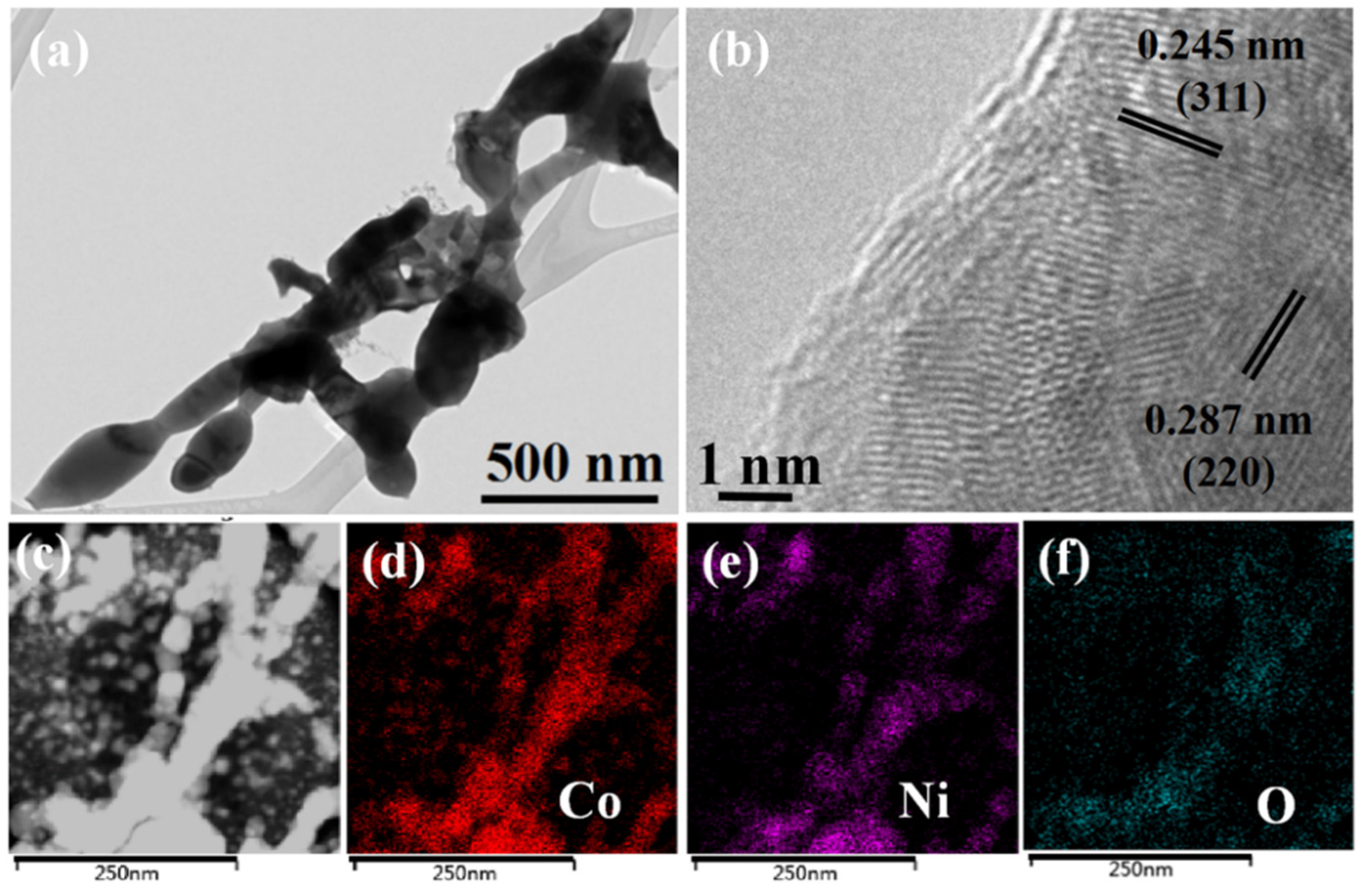
To further observe the structure and elemental distribution of NiCo2O4 annealed at 700 °C in air, transmission electron microscopy (TEM) with energy dispersive X-ray analysis (EDX) mapping was employed. As shown in the low-resolution TEM image (Figure 2a), the chain-like structure of NiCo2O4 was clearly observed. Differing from the morphology before annealing in the SEM image (Figure 1b), the NiCo2O4 nanowires were found to combine after annealing at 700 °C for 2 h in air. In the high-resolution TEM image, the lattice of NiCo2O4 was observed (Figure 2b). The obtained lattice spacings of d(220) = 0.287 nm and d(311) = 0.245 nm match well with the literature (d(220) = 0.282 nm and d(311) = 0.241 nm) [39]. To observe the elemental distribution in NiCo2O4, EDX mapping of Ni, Co, and O elements (Figure 2d–f) was employed. As shown in Figure 2d,e, strong signals from Ni and Co elements were detected, proving the existence of Ni and Co in the spinel phase. Moreover, the mapping of Co overlaps well with that of the Ni in the detected area, indicating the synthesis of the NiCo2O4 phase.
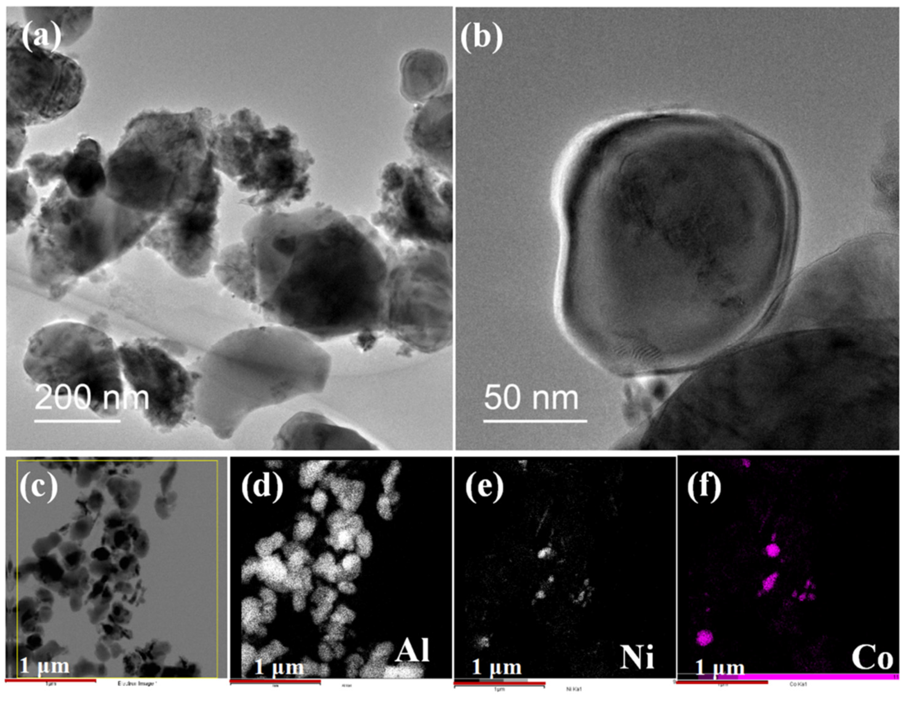
Figure 3 shows the structure and morphology of the NiCo/α–Al2O3 catalyst after ball milling of the mixed NiCo2O4 spinel and α–Al2O3 phase, and annealing at 700 °C in air. As shown in Figure 3a, isolated particles were observed in the low-resolution TEM image. Such a structure is expected to be beneficial for the catalytic deposition of the carbon phase during the catalytic process. Electron transparent particles with sizes smaller than 500 nm were found to be separately dispersed in the observed area. STEM and EDX mapping were employed to identify the composition of the transparent particles. In the EDX mapping (Figure 3d), strong Al signals were detected in the overlap area of the STEM image (Figure 3c), which confirms these particles existing as an Al2O3 phase. On the surface of Al2O3, particles with dark contrast were found to be attached. In the high-resolution TEM image (Figure 3b), a ring gap with different contrast was found to cover the surface of the Al2O3 catalyst, which further confirms the existence of the attachment. Based on the EDX mapping (Figure 3e,f), it can be concluded that these attached particles are NiCo2O4 catalysts.

2.2. Crystal Structure of Catalysts

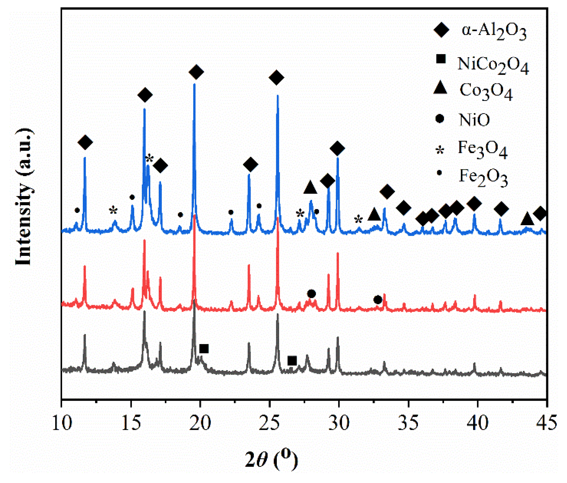
The freshly prepared α–Al2O3 containing catalysts were analyzed by powder X-ray diffraction (XRD) (Figure 4). Expectedly, a large fraction of the diffraction pattern appeared to be dominated by Al2O3 reflections (MATCH! entry number: 96-101-0915). Next, relatively weak reflections of Co3O4 (MATCH! entry number: 96-900-5895), NiO (MATCH! entry number: 96-101-0094), and NiCo2O4 (ICSD entry number: 181262), respectively, were assigned. All samples contained additional reflections, identified as iron oxides, namely Fe2O3 (MATCH! entry number: 96-101-1241) in Co/α–Al2O3, Fe2O3 and Fe3O4 (MATCH! entry number: 96-900-5813) in Ni/α–Al2O3, and Fe3O4 in NiCo/α–Al2O3. Most probably, the iron impurities result from the ball milling process using stainless steel balls and milling jars, as the impurity level is similar for all three samples. However, the appearance of the characteristic reflections in the corresponding XRD patterns proves the existence of the respective oxides in the catalyst samples [38,40,41,42,43].

2.3. Thermochemistry of Catalysts

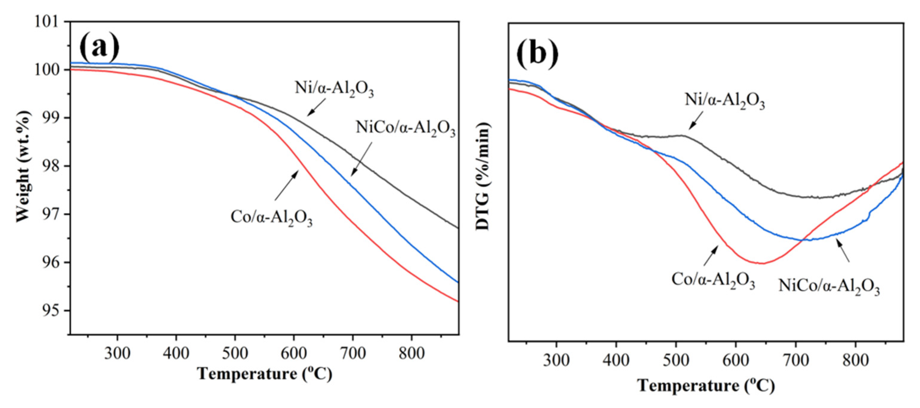
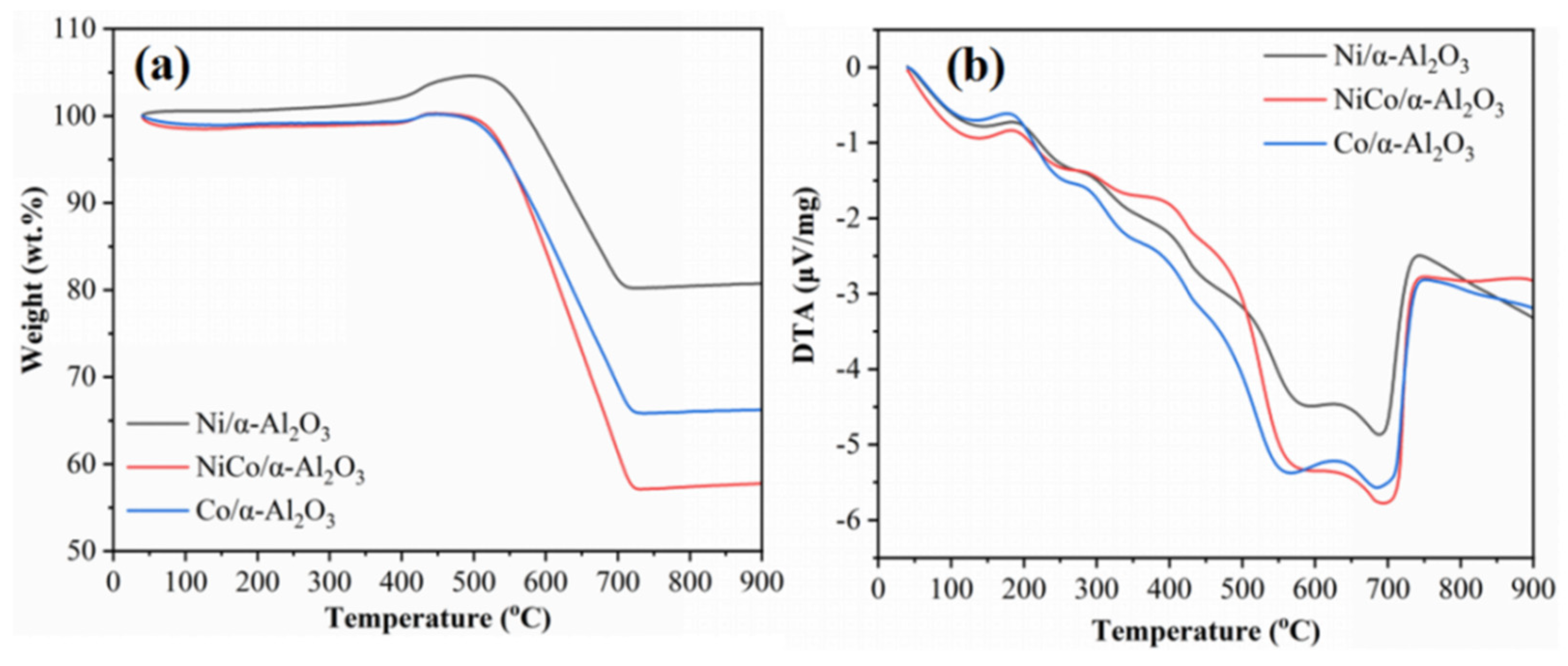
The thermogravimetric (TG) and differential thermogravimetric (DTG) curves of all batches of fresh catalysts with respect to temperature programmed reduction are shown in Figure 5. As shown in Figure 5a, all batches of samples exhibited weight loss due to the reduction of transition metal oxides. With increasing temperature, the weight loss also increased. At a temperature of 880 °C, the Co-based catalyst exhibited the highest weight loss of about 4.7 wt.%, indicating the easiest reduction for Co3O4. In Figure 5b, the catalysts showed a strong reduction peak in the temperature range between 500–850 °C, which agrees well with the weight loss behavior as noticed earlier (Figure 5a). For the Co/α–Al2O3 catalyst, the reduction peak was found to shift to a lower temperature compared to that of Ni/α–Al2O3 and NiCo/α–Al2O3. This can be explained by the different reduction temperatures of Ni and Co oxides [7,8]. Different from the catalysts prepared with the wet-impregnation method [7,8], where reduction peaks also appeared at a relatively low temperature (T ≤ 500 °C), only one strong reduction peak appeared in the temperature programmed reduction plots of the catalysts prepared in this work. The presence of a reduction peak at high temperatures indicates the strong interaction of the catalyst with the Al2O3 support [1,7,8].

2.4. Growth of Carbon Nanotubes Composites

In this part, both the catalytic behavior of pure NiCo-based spinel catalyst and NiCo/α–Al2O3, as well as the monometallic Ni/α–Al2O3 and Co/α–Al2O3 reference catalysts, were investigated.
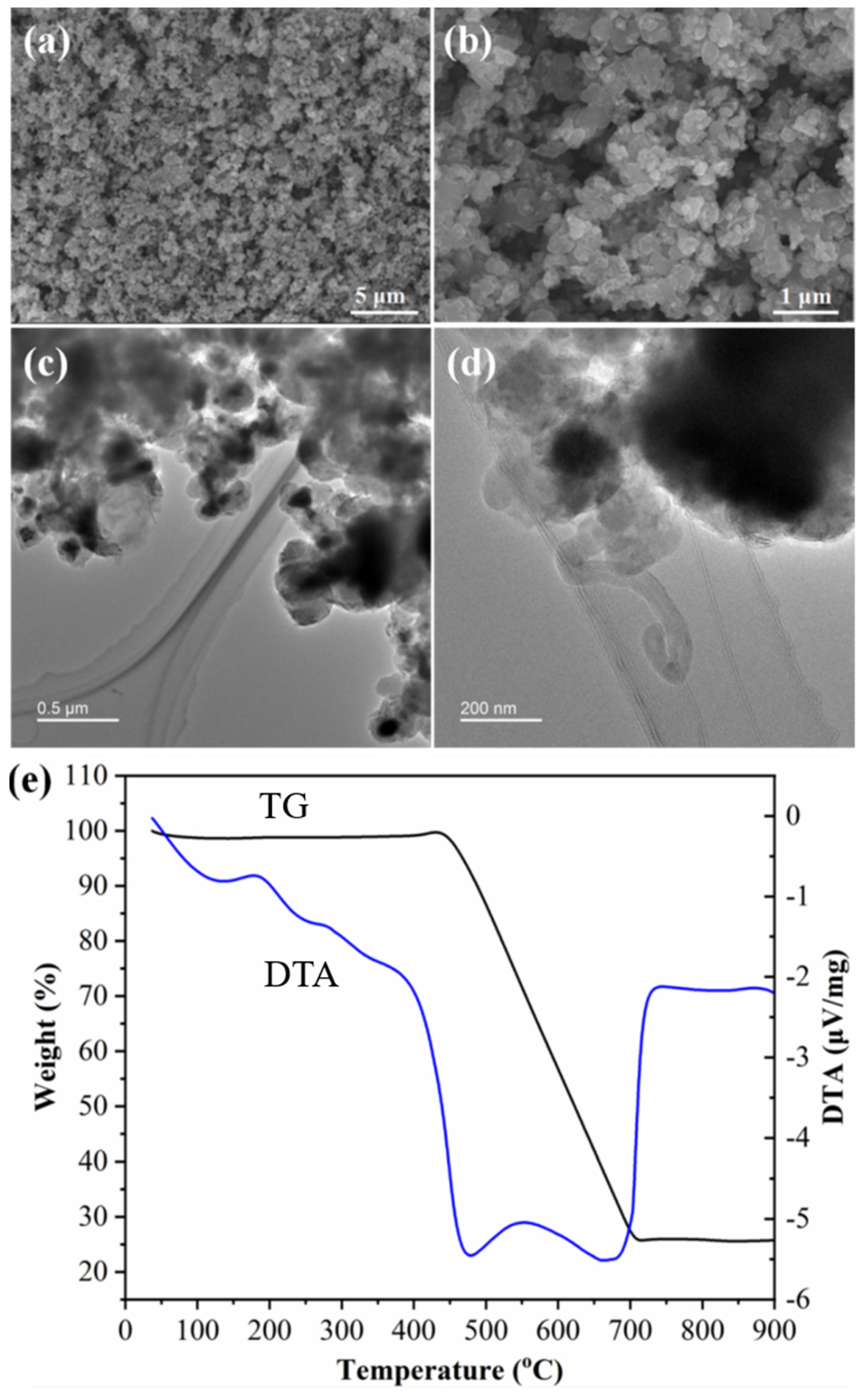
Figure 6a,b are the SEM images of the NiCo-based spinel catalyst after chemical vapor deposition of gaseous carbon species from the thermally decomposed post-consumer plastic at 800 °C. As shown in Figure 6a, the sea urchin-like 3D structure (shown in Figure 1a) was found to collapse after the CVD process. During the thermal decomposition of plastic, gaseous byproducts with reductive properties (e.g., H2) were released, which led to the reduction of NiCo2O4 as observed in thermal analysis (Figure 5). The obtained NiCo alloy derived from the reduction of NiCo2O4 would assemble into particles leading to the collapsing of the 3D structure. Unexpectedly, no CNTs were found to be generated after deposition (Figure 6a,b). To detect the material structure and composition after deposition, TEM images were employed. In Figure 6c, catalyst particles with dark contrast were found to be embedded in the composites. From the scale bar of the figure, it can be seen that the size of these particles is larger than 200 nm. In the high-resolution TEM image (Figure 6d), a single carbon nanotube with a length of <1 μm was observed, while most of the deposited carbon cannot assemble into CNTs. As reported, the generation of CNTs is greatly influenced by the dispersion state and particle size of the catalyst [44,45]. When the catalyst particle size is larger than 100 nm, the growth of CNTs is expected to be seriously prohibited [45]. Based on the TEM results, we predicate the failure of CNT growth results from the agglomeration of catalysts. Figure 6e shows the temperature-programmed oxidation (TPO) of the carbon phase/NiCo-based catalyst materials. In the TPO plot, a small hump between 450 °C and 500 °C was observed, which resulted from the oxidation of Ni and Co catalysts. With the temperature increase to 700 °C, a weight loss of ~76 wt.% accompanied by two exothermal peaks at 479 °C and 661 °C, respectively, occurred during oxidation, indicating that the NiCo2O4 catalyst possesses excellent performance in capturing the Cn species released by the decomposition of the plastic. To find the best employment of NiCo2O4 as a catalyst, a secondary phase that can stabilize and prevent the catalyst from agglomeration is needed.
Al2O3 and SiO2 as stable phases can effectively prevent the agglomeration of catalysts and have been widely used as supports in the growth of CNCs via thermo-chemical recycling of plastics [1,7,8,9,18,19]. Compared with SiO2, Al2O3 was reported to exhibit better interaction capability with transition metal-based catalysts [1,7,8,9]. In this work, to prevent the agglomeration of the catalyst, α-Al2O3 was employed. Apart from the supporting phase, the chemical composition of catalysts and catalytic reaction temperature also have critical influences on the carbon yield and CNC structure (e.g., aspect ratio and graphitic degree) [1,18,19]. It was reported that bimetallic catalysts typically exhibited better catalytic performance than their monometallic catalyst counterparts due to the better cracking ability of bimetallic catalysts [1,7,8]. In this work, the effect of the chemical composition of catalysts, as well as the catalytic reaction temperature on the carbon yield and morphology of CNCs were investigated.
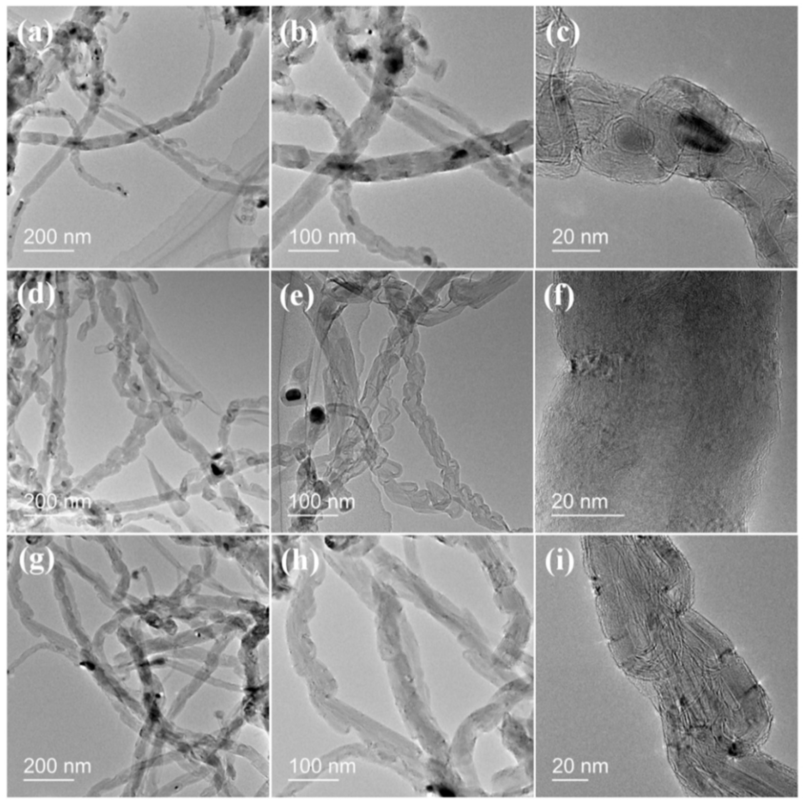
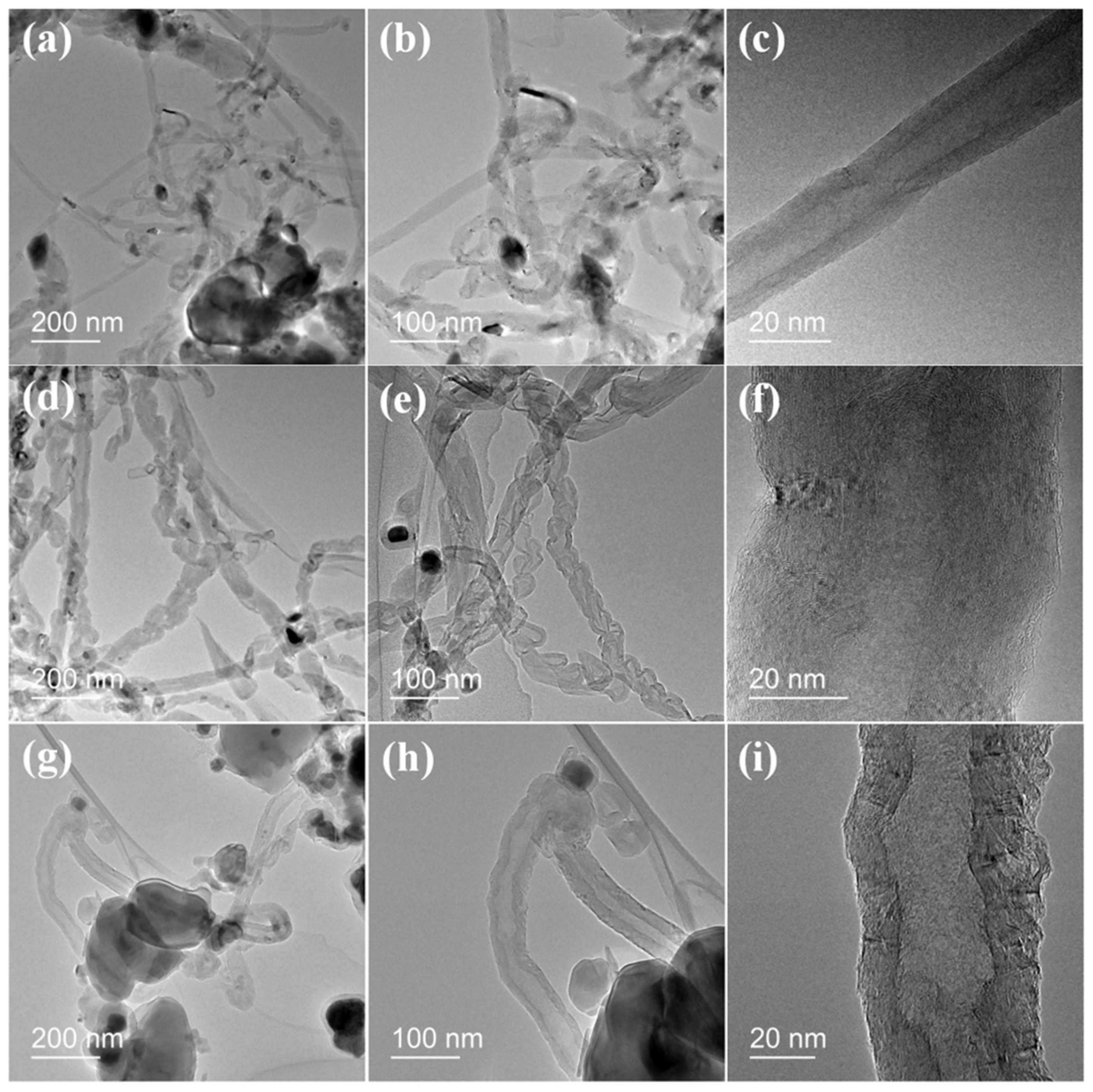
Figure 7 shows the morphology of the CNCs catalyzed with Ni/α–Al2O3, NiCo/α–Al2O3, and Co/α–Al2O3 at 900 °C. As shown in Figure 7a, filamentous carbons were found to be homogeneously generated on the surface of the Ni/α–Al2O3 catalyst, where the length of these filamentous carbon products can reach 10 μm. In the high magnification SEM image (Figure 7b), the filamentous carbons with diameters of larger than 100 nm were found to be interconnected with each other. Moreover, some bright particles with a size of 0.5 μm were found to decorate the filamentous carbons. It is speculated that these particles are graphite-covered Al2O3 particles. In the SEM images of CNCs catalyzed by NiCo/α–Al2O3 and Co/α–Al2O3, particles with similar morphology can also be observed. During the catalytic pyrolysis process, the catalysts attached to the surface of Al2O3 particles captured the Cn species, leading to the precipitation of solid carbon. Limited by the large particle size of Al2O3, the precipitated carbon cannot assemble into filamentous carbons leading to the growth of these graphite layers. Compared with the CNCs catalyzed by Ni and Co (Figure 7b,f), the filamentous carbon in the CNCs (Figure 7d) formed by the Ni/Co catalyst possesses a smaller diameter. To further observe the structure of these filamentous carbons, TEM images were employed. As shown in Figure 8, a hollow structure containing nanosized particles was observed for the filamentous carbons, proving them to be CNCs instead of carbon nanowire composites. Based on the literature [1,18,19,28,29,30], we predicate these particles to be metal catalysts. Same with the observation in SEM images, the diameter of CNCs varied with the catalyst type. As shown in the high-resolution TEM images (Figure 8b,e,h), CNCs catalyzed with bimetallic NiCo/α–Al2O3 catalyst possessed a smaller diameter than those catalyzed with Ni/α–Al2O3 and Co/α–Al2O3. The diameter of CNCs was determined by the particle size of the catalyst. It was reported that bimetallic alloy catalysts tended to be more difficult to agglomerate than their individual components [28,29,30]. In Figure 8c,f,i, a multi-walled structure of generated CNCs was observed. Interestingly, regardless of the catalyst type, the CNCs generated in this work always exhibited a bamboo-like structure. Based on the literature, the evolution of CNCs followed a “particle-wire-tube” growth mechanism [46]. This mechanism can be described by three steps, which are (a) capturing of Cn species by the catalyst particles and precipitation of carbon nanoparticles [47], (b) self-assembling of carbon nanoparticles into carbon nanowires, and (c) merging of nanoparticles and regrowth of graphitic layers (Figure 8c,f,i) and emptying of nanowire into nanotubes. In the first step, tiny carbon nanoparticles were formed by a condensation of gaseous carbon species with the assistance of the catalyst. Then, the carbon nanoparticles self-assembled into nanowires driven by an anisotropic interaction provided by the catalysts. Finally, the nanowires developed into nanotubes, as a consequence of particle coalescence and structural crystallization [46,47]. In the high-resolution TEM images (Figure 8c,f,i), an amorphous carbon layer was observed on the surface of CNCs. Similar observations have been previously reported [46].
To characterize the carbon yield and relative amount of different carbon (e.g., amorphous carbon and graphitic carbon) with respect to catalyst type, temperature-programmed oxidation of the CNCs was carried out (Figure 9). As shown in the weight loss plots, there is a small increase (2.5–4.4 wt.%) at the temperature range of 400 °C to 550 °C due to the oxidation of Ni and Co metals. The weight loss started at a temperature of 550 °C and stopped at a temperature of 710 °C. From the weight loss plots, Ni-based catalyst exhibited the least carbon deposit, where the residual weight was recorded to be as high as 82 wt.%. Through calculation with the weight of catalyst before and after deposition, the carbon yield of the corresponding material was only 13.0 wt.%. Followed by the Co-based catalyst, a weight loss of ~34 wt.% was recorded in the corresponding weight loss plot and the carbon yield increased accordingly to 18.3 wt.%. Among all these three catalysts, NiCo/α–Al2O3 catalyst exhibited the most carbon deposit reaching as high as 24.0 wt.%. In the corresponding weight loss plot, a weight loss of ~43 wt.% was recorded after the oxidation process. In the DTA plots (Figure 9b), two distinct exothermal peaks were recorded at a temperature of ~560 °C and 700 °C for all three catalysts. Based on the thermo-chemical stability of the carbon phase [7,8,9,18,19], the peak at around 560 °C is related to the oxidation of amorphous carbon while the peak at 700 °C stems from the oxidation of graphitic carbon.
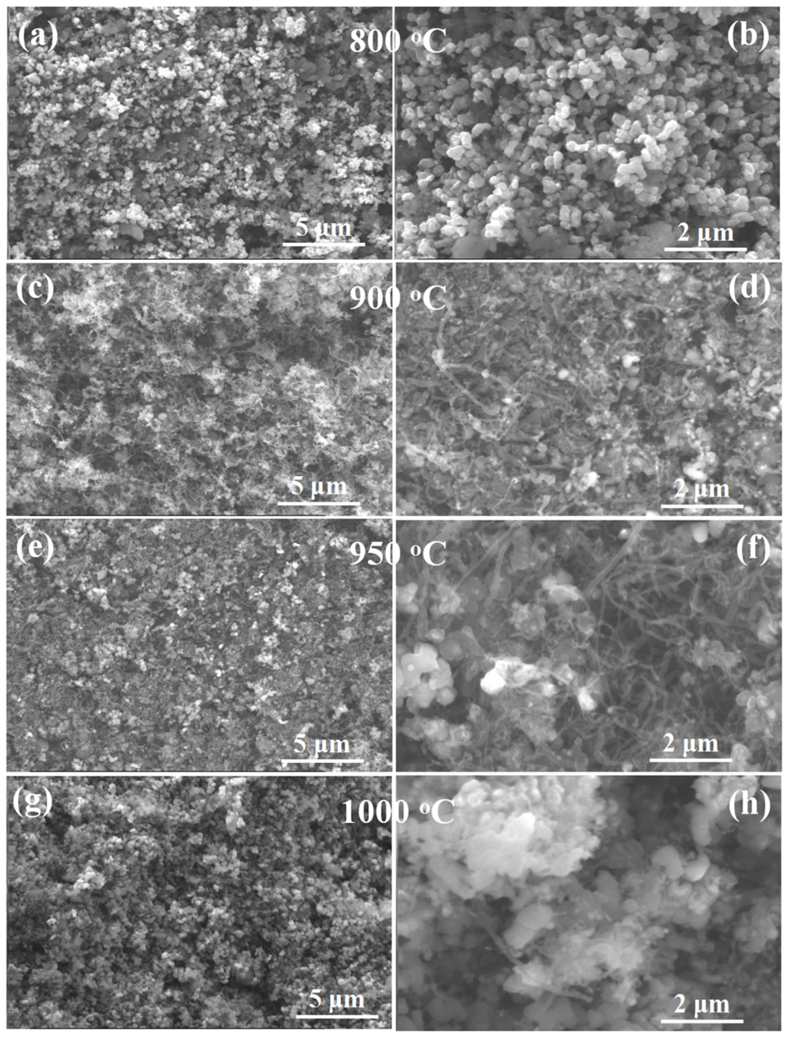
Besides the chemical composition, catalytic reaction temperature also influenced the performance of the catalyst. Figure 10 shows the SEM images of CNCs catalyzed with NiCo/α–Al2O3 at 800 °C, 900 °C, 950 °C, and 1000 °C, respectively. As shown in Figure 10a,b, no CNTs were found to be generated after catalyzing at 800 °C in the resultant CNCs. Calculations according to Equation (1) showed carbon yield to be as low as 12.5 wt.%. It might have resulted from the decreased catalytic activity of the catalyst after interacting with the Al2O3 phase at a relatively low temperature. When the temperature increased to 900 °C, a large amount of CNCs were generated on the surface of the catalyst homogeneously. In Figure 10c, dense CNC forests were observed. In the high magnification SEM image, the CNCs exhibited a smooth surface and a length of several micrometers. Meanwhile, with the increase of temperature, the carbon yield also exhibited a corresponding increase from 12.5 wt.% to 24.0 wt.%, which is further aided by the TGA results. With the further increase of temperature to 950 °C, the carbon yield reached its largest value in this work, as large as 25.5 wt.%. From the SEM images (Figure 10e,f), it can be seen that the diameter of CNCs became smaller while the length of CNCs increased when increasing the temperature to 950 °C, indicating the improvement in the catalytic activity. However, when the temperature increased to 1000 °C, the dense CNC forest disappeared. It resulted from the sintering of the metallic catalyst particles at high temperatures, leading to a deactivation of the catalyst [1]. Correspondingly, the carbon yield also exhibited a significant decrease and dropped to 7.5 wt.%. From the high magnification SEM image (Figure 10h), only a few CNCs with a small aspect ratio were observed.
Figure 11 shows the TEM images of CNCs produced with the NiCo/α–Al2O3 catalyst at 900 °C, 950 °C, and 1000 °C. From the low-resolution TEM images (Figure 11a,d), it can be seen that the CNCs generated at 900 °C and 950 °C possess a large aspect ratio due to the excellent catalytic activity. However, in Figure 11g, only some CNC embryos can be observed, which agrees well with the SEM observations (Figure 10h). This can be explained by the deactivation of catalysts at high temperatures.
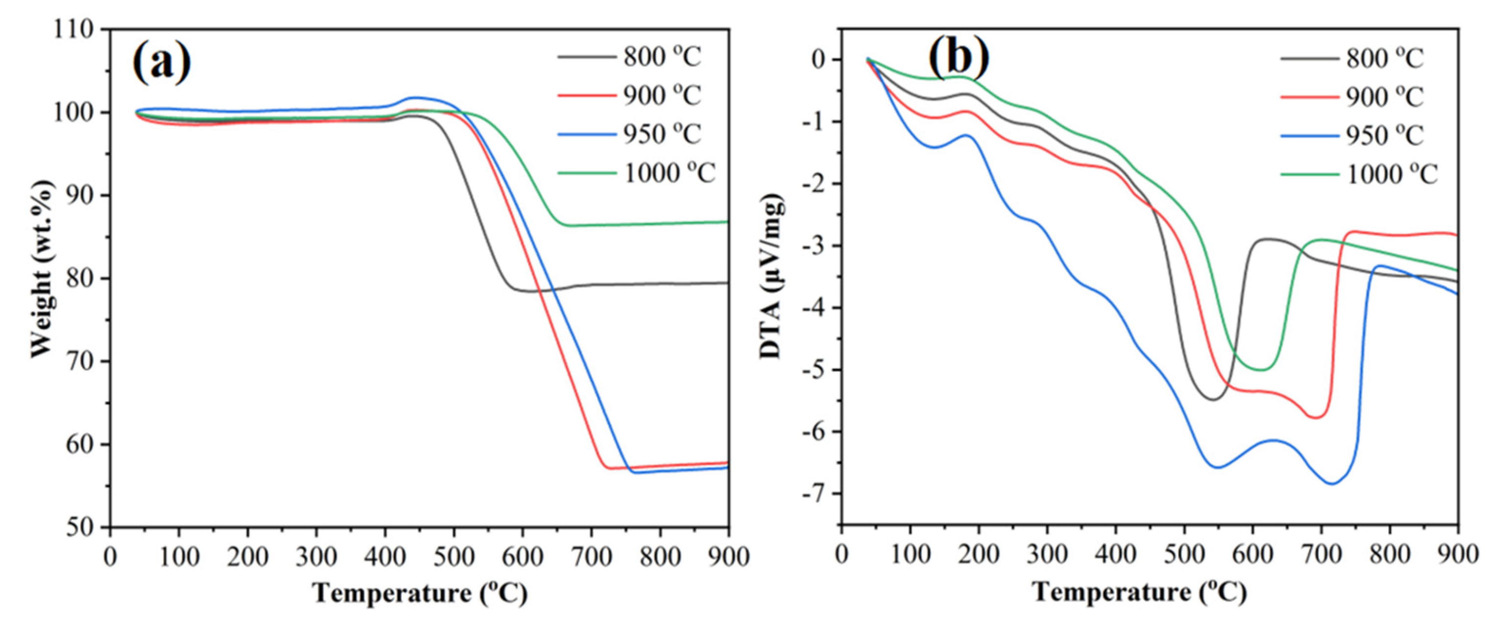
Figure 12 shows the temperature-programmed oxidation behavior of the CNCs. As shown in Figure 12a, the weight loss in these plots exhibited the same varying tendency as the carbon yield. For the CNC sample catalytically deposited at 800 °C, the weight loss stopped at the temperature of 550 °C with a weight loss of ~21 wt.%. Differing from this sample, the weight loss of the other samples stopped at a higher temperature (~700 °C). We suggest this phenomenon resulted from the poor graphitic degree of the CNCs catalyzed deposited at 800 °C (Figure 12a) [1,8,9,28,29,30]. With the increase of catalytic reaction temperature, the weight loss of the corresponding sample increased, which agrees well with the carbon yield. When the catalytic reaction temperature was 950 °C, the weight loss reached 42.7 wt.%. With the further increase of catalytic reaction temperature, the weight loss decreased to 12 wt.% due to the decreased catalytic activity of the catalyst. As shown in Figure 12b, two distinct peaks were recorded at the temperatures of ~550 °C and 720 °C for the DTA plots of samples catalyzed at 900 °C and 950 °C, while only one peak appeared in the DTA of the other two samples. From the DTA plots, it can be seen that most of the carbon deposited on the surface of the catalyst at 800 °C and 1000 °C was amorphous carbon, which can also be confirmed by the below presented Raman results.
Raman spectra (Figure 13) of all batches of CNCs were employed to characterize the graphitization degree of the carbon phase deposited onto the surface of the catalysts during the pyrolysis catalytic process. The D band in the Raman spectra at around 1350 cm−1 is associated with the signal from the disordered carbon, while the G band at around 1580 cm−1 is caused by vibration of the ordered graphite carbon atoms [48,49,50]. The intensity ratio of the D band (ID) to the G band (IG) is employed to determine the graphitization degree of the carbon phase. The G’ band at the wavelength of 2710 cm−1 can reflect the purity of CNCs. The ratio IG’/IG can be used to describe the purity of the CNCs [8,9,29,30]. As shown in Figure 13a, the carbon phase catalyzed at 800 °C exhibited an ID:IG value of 1.29, indicating poor graphitization degree. This is due to the poor catalytic activity of the catalyst at a relatively low temperature. With the temperature increase, the value of ID:IG decreased significantly, indicating an improved graphitization degree. At a temperature of 900 °C and 950 °C, the values of ID:IG reached 0.55 and 0.57, respectively. The improvement of graphitization degree can be ascribed to better catalytic activity at a higher temperature. For the carbon phase deposited at a fixed temperature on Ni/α-Al2O3, NiCo/α-Al2O3, and Co/α–Al2O3, the graphitization degree also varied with the catalyst composition. The carbons deposited on Ni/αffAl2O3 and Co/α–Al2O3 exhibited a better graphitization degree than the ones deposited on NiCo/α–Al2O3, even though they possess inferior catalytic performance than NiCo/α–Al2O3. Due to the deactivation of catalysts at 1000 °C, the resultant CNC exhibited an increased value of ID:IG (0.74), indicating a decreased graphitization degree. In addition, the IG’/IG values of resultant CNCs in this work varied from 0.50 to 0.58, indicating that the CNCs possessed relatively high purity [7,8,28,29].

3. Experimental Part

3.1. Catalyst Preparation

In this work, the NiCo2O4 catalysts were synthesized with a hydrothermal method. To start with, 0.4 mmol Ni(NO3)2·6H2O (98 %, Alfa Aesar, Kandel, Germany), 0.8 mmol Co(NO3)2·6H2O (98%, Alfa Aesar, Kandel, Germany), and 1.2 mmol urea (98+%, Alfa Aesar, Kandel, Germany) were dissolved in 30 mL deionized (DI) water and stirred for 30 min to form a solution [38]. Then, 0.72 g α–Al2O3 (99.99%, Alfa Aesar, Germany) was introduced into the solution with the assistance of magnetic stirring. After stirring for 1 h, the dispersion was transferred into a 50 mL Teflon-lined autoclave and maintained at 120 °C for 8 h in the oven. After cooling to room temperature, the precipitations were collected with centrifugation at the speed of 5000 r/min for 10 min and freeze-dried. Then the NiCo2O4/α–Al2O3 mixtures were ball milled (Pulversitte 7 premium line, Fritsch GmbH, Idar-Oberstein, Germany; stainless steel balls and jars) for 10 h with a speed of 300 r/min. Finally, the ball milled catalysts were annealed at 700 °C for 2 h in air. The control samples of NiO/α–Al2O3 and Co3O4/α–Al2O3 with the same molar ratio of metal to Al2O3 were prepared with identical conditions.

3.2. Experimental Setup and Procedure

The thermo-chemical recycling of waste plastics was conducted in a modified two-stage reactor. The experimental setup consists of two connected Al2O3 tube furnaces (one for pyrolysis and another for catalysis) and a gas supply system. In this work, both the influence of catalyst type (oxides of Ni, Co and bimetallic Ni/Co supported by α–Al2O3) and the catalytic reaction temperature (800 °C, 900 °C, 950 °C, and 1000 °C) on the morphology of carbon nanotube composites and yield of carbon were investigated. For convenience, the corresponding catalysts were abbreviated as Ni/α–Al2O3, Co/α–Al2O3, and NiCo/α–Al2O3 catalysts. For each batch, 1 g of catalyst was spread on the Al2O3 bed reactor and placed in the center of the furnace for the catalytic reaction. An Al2O3 crucible with 4 g plastic (polyethylene, cut from a spent bottle of absolute ethanol) was placed in the center of the pyrolytic furnace. Before the heating of the plastic, the catalytic furnace was preheated to the set temperature (800 °C, 900 °C, 950 °C, and 1000 °C). The plastic was heated at a heating rate of 200 °C/h from 50 °C to 800 °C and held at 800 °C for 1 h in Air atmosphere.

3.3. Characterization

Scanning electron microscopy (SEM) (FEI, Eindhoven, The Netherlands) was employed to observe the morphology of catalysts and CNC samples. The structure of the catalysts and CNC samples were observed with transmission electron microscopy (TEM) (TEM; JEM2100F, JEOL, Tokyo, Japan). Elemental mapping images were recorded using energy-dispersive X-ray spectroscopy (EDX detector: X-Max 80 SDD Detector, Oxford) attached to TEM. The crystal structure of the obtained catalysts was characterized by a STOE STADI MP (STOE GmbH & Cie, Darmstadt, Germany) X-ray diffractometer in a transmission geometry (Mo 1 radiation). The phase identification was carried out using MATCH! (version 3.12 build 210, CRYSTAL IMPACT Dr. H. Putz & Dr. K. Brandenburg GbR, Bonn, Germany) in combination with COD (version 2021.06.14) [51,52,53,54,55,56,57] and the ICSD (version 4.6.0 (build 20210419-1300), FIZ Karlsruhe–Leibniz-Institut für Informationsinfrastruktur GmbH, Eggenstein-Leopoldshafen, Germany) database. The weight loss behavior of the CNCs as a function of temperature was characterized by temperature-programmed oxidation (TPO) using the thermogravimetric analyzer (TGA, STA449F3, Netzsch Gerätebau GmbH, Selb, Germany) and simultaneous differential thermal analysis (DTA). Derivative thermal gravimetry (DTG) analysis, namely temperature programmed reduction (TPR) of the fresh catalysts was undertaken in a reductive atmosphere (5 vol.% H2/95 vol.% Ar). Raman spectra recorded from 500 to 3500 cm−1 via a micro-Raman HR8000 spectrometer (Horiba Jobin Yvon, Bensheim, Germany) with a laser wavelength of 514.5 nm were employed to characterize the graphitic degree of CNCs. Carbon yield was determined by the weight difference between the fresh catalyst (Wcat) and carbon deposited catalyst (Wcar+cat) divided by the weight of plastic (Wpla), as shown in Equation (1):
C a r b o n   y i e l d = W car + cat W c a t W p l a

4. Conclusions

Multi-walled carbon nanotube composites were generated via catalytic pyrolysis of post-consumer plastic with the NiCo-based spinel/α–Al2O3 catalyst. Due to the better cracking ability of the carbon-hydrogen bonds, the Ni/Co-based bimetallic catalyst exhibited better carbon deposit capability than the respective monometallic catalysts at the same catalytic reaction temperature. With the variation of the catalytic reaction temperature, the catalytic activity of the Ni/Co-based catalyst varied, which led to the variation of carbon yield, and morphology and structure of CNCs. At a temperature of 950 °C, the Ni/Co catalyst exhibited the best catalytic activity in the temperature range (800–1000 °C) investigated in this work and the carbon yield can reach as high as 25.5 wt.%. Regardless of catalyst composition and catalytic reaction temperature, the CNCs generated in this work exhibited a bamboo-like structure while the growth of CNCs followed the “particle-wire-tube” mechanism. This work has identified the potential application of spinels as catalysts for the recycling of post-consumer plastic by a catalytic pyrolysis method. Considering the high potential of CNCs in energy storage, the as-prepared CNCs will be investigated as long-time stable electrode materials in upcoming research work.

Author Contributions

X.L.: Investigation, Methodology, Validation, Writing—original draft. W.X.: Methodology, Validation, Writing—original draft. M.W.: Methodology, Investigation, writing—review and editing. H.D.: Investigation, writing—review and editing. G.C.: Validation, writing—review and editing. D.M.D.C.: Investigation. K.L.-W.: Investigation. L.M.-L.: Validation, writing—review and editing. R.R.: Writing—review and editing. A.W.: Funding acquisition, Conceptualization, Supervision, writing—review and editing. All authors have read and agreed to the published version of the manuscript.

Funding

This research was funded by German Federal Ministry of Education and Research within the NexPlas project (project number: 03SF0618B). The APC was funded by the Deutsche Forschungsgemeinschaft (DFG—German research Foundation) and the Open Access Publishing Fund of the Technical University of Darmstadt.

Data Availability Statement

Not applicable.

Acknowledgments

M.W. and A.W. highly acknowledge the funding by the German Federal Ministry of Education and Research within the NexPlas project (project number: 03SF0618B). All authors acknowledge the funding by the Deutsche Forschungsgemeinschaft (DFG—German research Foundation) and the Open Access Publishing Fund of the Technical University of Darmstadt for the APC.

Conflicts of Interest

The authors declare that no conflict of interest exists for this research study.

References

  1. Zhang, Y.; Zhu, H.; Yao, D.; Williams, P.T.; Wu, C.; Xu, D.; Qiang, H.; George, M.; Lu, Y.; Ming, Z.; et al. Thermo-chemical conversion of carbonaceous waste for CNT and hydrogen productions: A review. Sustain. Energy Fuels 2021, 5, 4173–4208. [Google Scholar] [CrossRef]
  2. Al-Enizi, A.M.; Ahmed, J.; Ubaidullah, M.; Shaikh, S.F.; Ahamad, T.; Naushad, M.; Zheng, G. Utilization of waste polyethylene terephthalate bottles to develop metal-organic frameworks for energy applications: A clean and feasible approach. J. Clean. Prod. 2020, 248, 119251. [Google Scholar] [CrossRef]
  3. Vanapalli, K.R.; Sharma, H.B.; Ranjan, V.P.; Samal, B.; Bhattacharya, J.; Dubey, B.K.; Goel, S. Challenges and strategies for effective plastic waste management during and post COVID-19 pandemic. Sci. Total Environ. 2021, 750, 141514. [Google Scholar] [CrossRef] [PubMed]
  4. Rillig, M.C.; Lehmann, A. Microplastic in terrestrial ecosystems. Science 2020, 368, 1430–1431. [Google Scholar] [CrossRef]
  5. Al-Enizi, A.M.; Ubaidullah, M.; Ahmed, J.; Ahamad, T.; Ahmad, T.; Shaikh, S.F.; Naushad, M. Synthesis of NiOx@ NPC composite for high-performance supercapacitor via waste PET plastic-derived Ni-MOF. Compos. Part B. Eng. 2020, 183, 107655. [Google Scholar] [CrossRef]
  6. Weckhuysen, B.M. Creating value from plastic waste. Science 2020, 370, 400–401. [Google Scholar] [CrossRef]
  7. Yao, D.; Zhang, Y.; Williams, P.T.; Yang, H.; Chen, H. Co-production of hydrogen and carbon nanotubes from real-world waste plastics: Influence of catalyst composition and operational parameters. Appl. Catal. B Environ. 2018, 221, 584–597. [Google Scholar] [CrossRef]
  8. Yao, D.; Yang, H.; Hu, Q.; Chen, Y.; Chen, H.; Williams, P.T. Carbon nanotubes from post-consumer waste plastics: Investigations into catalyst metal and support material characteristics. Appl. Catal. B Environ. 2021, 280, 119413. [Google Scholar] [CrossRef]
  9. Yao, D.; Wu, C.; Yang, H.; Zhang, Y.; Nahil, M.A.; Chen, Y.; Chen, H. Co-production of hydrogen and carbon nanotubes from catalytic pyrolysis of waste plastics on Ni-Fe bimetallic catalyst. Energy Convers. Manag. 2017, 148, 692–700. [Google Scholar] [CrossRef]
  10. De Volder, M.F.; Tawfick, S.H.; Baughman, R.H.; Hart, A.J. Carbon nanotubes: Present and future commercial applications. Science 2013, 339, 535–539. [Google Scholar] [CrossRef] [Green Version]
  11. Herrera-Herrera, A.V.; González-Curbelo, M.Á.; Hernández-Borges, J.; Rodríguez-Delgado, M.Á. Carbon nanotubes applications in separation science: A review. Anal. Chim. Acta 2012, 734, 1–30. [Google Scholar] [CrossRef] [PubMed]
  12. Thostenson, E.T.; Ren, Z.; Chou, T.W. Advances in the science and technology of carbon nanotubes and their composites: A review. Compos. Sci. Technol. 2001, 61, 1899–1912. [Google Scholar] [CrossRef] [Green Version]
  13. Kumar, M.; Ando, Y. Chemical vapor deposition of carbon nanotubes: A review on growth mechanism and mass production. J. Nanosci. Nanotechnol. 2010, 10, 3739–3758. [Google Scholar] [CrossRef] [PubMed] [Green Version]
  14. Esteves, L.M.; Oliveira, H.A.; Passos, F.B. Carbon nanotubes as catalyst support in chemical vapor deposition reaction: A review. J. Ind. Eng. Chem. 2018, 65, 1–12. [Google Scholar] [CrossRef]
  15. Weidenkaff, A.; Ebbinghaus, S.G.; Lippert, T. Ln1−xAxCoO3 (Ln = Er, La; A = Ca, Sr)/Carbon Nanotube Composite Materials Applied for Rechargeable Zn/Air Batteries. Chem. Mater. 2002, 14, 1797–1805. [Google Scholar] [CrossRef]
  16. Züttel, A.; Nützenadel, C.; Sudan, P.; Mauron, P.; Emmenegger, C.; Rentsch, S.; Schlapbach, L.; Weidenkaff, A.; Kiyobayashi, T. Hydrogen sorption by carbon nanotubes and other carbon nanostructures. J. Alloys Compd. 2002, 330, 676–682. [Google Scholar] [CrossRef]
  17. Manawi, Y.M.; Samara, A.; Al-Ansari, T.; Atieh, M.A. A review of carbon nanomaterials’ synthesis via the chemical vapor deposition (CVD) method. Materials 2018, 11, 822. [Google Scholar] [CrossRef] [Green Version]
  18. Wu, C.; Nahil, M.A.; Miskolczi, N.; Huang, J.; Williams, P.T. Production and application of carbon nanotubes, as a co-product of hydrogen from the pyrolysis-catalytic reforming of waste plastic. Process Saf. Environ. Prot. 2016, 103, 107–114. [Google Scholar] [CrossRef]
  19. Borsodi, N.; Szentes, A.; Miskolczi, N.; Wu, C.; Liu, X. Carbon nanotubes synthetized from gaseous products of waste polymer pyrolysis and their application. J. Anal. Appl. Pyrol. 2016, 120, 304–313. [Google Scholar] [CrossRef]
  20. Wen, X.; Chen, X.; Tian, N.; Gong, J.; Liu, J.; Rümmeli, M.H.; Tang, T. Nanosized carbon black combined with Ni2O3 as “universal” catalysts for synergistically catalyzing carbonization of polyolefin wastes to synthesize carbon nanotubes and application for supercapacitors. Environ. Sci. Technol. 2014, 48, 4048–4055. [Google Scholar] [CrossRef]
  21. Acomb, J.C.; Wu, C.; Williams, P.T. The use of different metal catalysts for the simultaneous production of carbon nanotubes and hydrogen from pyrolysis of plastic feedstocks. Appl. Catal. B Environ. 2016, 180, 497–510. [Google Scholar] [CrossRef] [Green Version]
  22. Lua, A.C.; Wang, H.Y. Hydrogen production by catalytic decomposition of methane over Ni-Cu-Co alloy particles. Appl. Catal. B Environ. 2014, 156, 84–93. [Google Scholar] [CrossRef]
  23. Cartwright, R.; Esconjauregui, S.; Hardeman, D.; Bhardwaj, S.; Weatherup, R.; Guo, Y.; Robertson, J. Low temperature growth of carbon nanotubes on tetrahedral amorphous carbon using Fe–Cu catalyst. Carbon 2015, 81, 639–649. [Google Scholar] [CrossRef]
  24. Wu, C.; Williams, P.T. Investigation of coke formation on Ni-Mg-Al catalyst for hydrogen production from the catalytic steam pyrolysis-gasification of polypropylene. Appl. Catal. B Environ. 2010, 96, 198–207. [Google Scholar] [CrossRef]
  25. Wu, C.; Williams, P.T. Hydrogen production by steam gasification of polypropylene with various nickel catalysts. Appl. Catal. B Environ. 2009, 87, 152–161. [Google Scholar] [CrossRef]
  26. Joshi, R.; Engstler, J.; Houben, L.; Bar Sadan, M.; Weidenkaff, A.; Mandaliev, P.; Issanin, A.; Schneider, J.J. Catalyst Composition, Morphology and Reaction Pathway in the Growth of “Super-Long” Carbon Nanotubes. ChemCatChem 2010, 2, 1069–1073. [Google Scholar] [CrossRef]
  27. Weidenkaff, A.; Ebbinghaus, S.G.; Mauron, P.; Reller, A.; Zhang, Y.; Züttel, A. Metal nanoparticles for the production of carbon nanotube composite materials by decomposition of different carbon sources. Mater. Sci. Eng. C 2002, 19, 119–123. [Google Scholar] [CrossRef]
  28. Nahil, M.; Wu, C.; Williams, P.T. Influence of metal addition to Ni-based catalysts for the co-production of carbon nanotubes and hydrogen from the thermal processing of waste polypropylene. Fuel Process. Technol. 2015, 130, 46–53. [Google Scholar] [CrossRef]
  29. Yao, D.; Wang, C. Pyrolysis and in-line catalytic decomposition of polypropylene to carbon nanomaterials and hydrogen over Fe-and Ni-based catalysts. Appl. Energy 2020, 265, 114819. [Google Scholar] [CrossRef]
  30. Yao, D.; Li, H.; Dai, Y.; Wang, C.H. Impact of temperature on the activity of Fe-Ni catalysts for pyrolysis and decomposition processing of plastic waste. Chem. Eng. J. 2021, 408, 127268. [Google Scholar] [CrossRef]
  31. Kefeni, K.K.; Mamba, B.B.; Msagati, T.A. Application of spinel ferrite nanoparticles in water and wastewater treatment: A review. Sep. Purif. Technol. 2017, 188, 399–422. [Google Scholar] [CrossRef]
  32. Narang, S.B.; Pubby, K. Nickel spinel ferrites: A review. J. Magn. Magn. Mater. 2021, 519, 167163. [Google Scholar] [CrossRef]
  33. Ganesh, I. A review on magnesium aluminate (MgAl2O4) spinel: Synthesis, processing and applications. Int. Mater. Rev. 2013, 58, 63–112. [Google Scholar] [CrossRef]
  34. Zhao, X.; Mao, L.; Cheng, Q.; Li, J.; Liao, F.; Yang, G.; Chen, L. Two-dimensional spinel structured Co-based materials for high performance supercapacitors: A critical review. Chem. Eng. J. 2020, 387, 124081. [Google Scholar] [CrossRef]
  35. Li, Y.; Yuan, Z.; Meng, F. Spinel-Type Materials Used for Gas Sensing: A Review. Sensors 2020, 20, 5413. [Google Scholar] [CrossRef]
  36. Mameli, V.; Angotzi, M.S.; Cara, C.; Cannas, C. Liquid phase synthesis of nanostructured spinel ferrites—A review. J. Nanosci. Nanotechnol. 2019, 19, 4857–4887. [Google Scholar] [CrossRef]
  37. Dou, S. Review and prospects of Mn-based spinel compounds as cathode materials for lithium-ion batteries. Ionics 2015, 21, 3001–3030. [Google Scholar] [CrossRef]
  38. Liu, Z.Q.; Xu, Q.Z.; Wang, J.Y.; Li, N.; Guo, S.H.; Su, Y.Z.; Chen, S. Facile hydrothermal synthesis of urchin-like NiCo2O4 spheres as efficient electrocatalysts for oxygen reduction reaction. Int. J. Hydrog. Energy 2013, 38, 6657–6662. [Google Scholar] [CrossRef]
  39. Gu, Y.J.; Chen, Y.B.; Liu, H.Q.; Wang, Y.M.; Wang, C.L.; Wu, H.K. Structural characterization of layered LiNi0.85−xMnxCo0.15O2 with x = 0, 0.1, 0.2 and 0.4 oxide electrodes for Li batteries. J. Alloys Compd. 2011, 509, 7915–7921. [Google Scholar] [CrossRef]
  40. Bulavchenko, O.A.; Cherepanova, S.V.; Tsybulya, S.V. In situ XRD investigation of Co3O4 reduction. In Eleventh European Powder Diffraction Conference; Oldenbourg Wissenschaftsverlag: München, Germany, 2015; pp. 329–334. [Google Scholar]
  41. Bartůněk, V.; Huber, Š.; Sedmidubský, D.; Sofer, Z.; Šimek, P.; Jankovský, O. CoO and Co3O4 nanoparticles with a tunable particle size. Ceram. Int. 2014, 40, 12591–12595. [Google Scholar] [CrossRef]
  42. Xu, J.; Wu, L.; Liu, Y.; Zhang, J.; Liu, J.; Shu, S.; Hu, Y. NiO-rGO composite for supercapacitor electrode. Surf. Interfaces 2020, 18, 100420. [Google Scholar] [CrossRef]
  43. Rahdar, A.; Aliahmad, M.; Azizi, Y. NiO nanoparticles: Synthesis and characterization. J. Nanostruct. 2015, 5, 145–151. [Google Scholar]
  44. Kong, L.; Yin, X.; Yuan, X.; Zhang, Y.; Liu, X.; Cheng, L.; Zhang, L. Electromagnetic wave absorption properties of graphene modified with carbon nanotube/poly (dimethyl siloxane) composites. Carbon 2014, 73, 185–193. [Google Scholar] [CrossRef]
  45. Liu, X.; Yin, X.; Kong, L.; Li, Q.; Liu, Y.; Duan, W.; Cheng, L. Fabrication and electromagnetic interference shielding effectiveness of carbon nanotube reinforced carbon fiber/pyrolytic carbon composites. Carbon 2014, 68, 501–510. [Google Scholar] [CrossRef]
  46. Du, G.; Feng, S.; Zhao, J.; Song, C.; Bai, S.; Zhu, Z. Particle–wire–tube mechanism for carbon nanotube evolution. J. Am. Chem. Soc. 2006, 128, 15405–15414. [Google Scholar] [CrossRef]
  47. Deck, C.P.; Vecchio, K. Growth mechanism of vapor phase CVD-grown multi-walled carbon nanotubes. Carbon 2005, 43, 2608–2617. [Google Scholar] [CrossRef]
  48. Liu, X.; Xu, H.; Xie, F.; Fasel, C.; Yin, X.; Riedel, R. Highly flexible and ultrathin Mo2C film via in-situ growth on graphene oxide for electromagnetic shielding application. Carbon 2020, 163, 254–264. [Google Scholar] [CrossRef]
  49. Liu, X.; Xu, H.; Xie, F.; Yin, X.; Riedel, R. Light-weight and highly flexible TaC modified PyC fiber fabrics derived from cotton fiber textile with excellent electromagnetic shielding effectiveness. Chem. Eng. J. 2020, 387, 124085. [Google Scholar] [CrossRef]
  50. Li, M.; Chai, N.; Liu, X.; Xie, W.; Wang, G.; Qu, F.; Riedel, R. Sustainable Paper Templated Ultrathin, Light-Weight and Flexible Niobium Carbide Based Films against Electromagnetic Interference. Carbon 2021, 183, 929–939. [Google Scholar] [CrossRef]
  51. Vaitkus, A.; Merkys, A.; Gražulis, S. Validation of the Crystallography Open Database using the Crystallographic Information Framework. J. App. Crystallogr. 2021, 54, 661–672. [Google Scholar] [CrossRef]
  52. Quirós, M.; Gražulis, S.; Girdzijauskaitė, S.; Merkys, A.; Vaitkus, A. Using SMILES strings for the description of chemical connectivity in the Crystallography Open Database. J. Cheminform. 2018, 10, 1–17. [Google Scholar] [CrossRef] [PubMed]
  53. Merkys, A.; Vaitkus, A.; Butkus, J.; Okulič-Kazarinas, M.; Kairys, V.; Gražulis, S. COD::CIF::Parser: An error-correcting CIF parser for the Perl language. J. App. Crystallogr. 2016, 249, 92–301. [Google Scholar] [CrossRef] [PubMed] [Green Version]
  54. Gražulis, S.; Merkys, A.; Vaitkus, A.; Okulič-Kazarinas, M. Computing stoichiometric molecular composition from crystal structures. J. App. Crystallogr. 2015, 48, 85–91. [Google Scholar] [CrossRef] [PubMed] [Green Version]
  55. Gražulis, S.; Daškevič, A.; Merkys, A.; Chateigner, D.; Lutterotti, L.; Quirós, M.; Serebryanaya, N.R.; Moeck, P.; Downs, R.T.; LeBail, A. Crystallography Open Database (COD): An open-access collection of crystal structures and platform for world-wide collaboration. Nucleic Acids Res. 2012, 40, 420–427. [Google Scholar] [CrossRef] [PubMed]
  56. Grazulis, S.; Chateigner, D.; Downs, R.T.; Yokochi, A.T.; Quiros, M.; Lutterotti, L.; Manakova, E.; Butkus, J.; Moeck, P.; Le Bail, A. Crystallography Open Database—An open-access collection of crystal structures. J. App. Crystallogr. 2009, 42, 726–729. [Google Scholar] [CrossRef]
  57. Downs, R.T.; Hall-Wallace, M. The American Mineralogist Crystal Structure Database. Am. Mineral. 2003, 88, 247–250. [Google Scholar]
Figure 1. Low magnification scanning electron microscopy (SEM) images of NiCo2O4 (a) before and (c) after annealing at 700 °C; and high magnification SEM images of NiCo2O4 (b) before and (d) after annealing at 700 °C.
Catalysts 11 01353 g001
Figure 2. Low (a) and high (b) resolution transmission electron microscopy (TEM) images of NiCo2O4 annealed at 700 °C, scanning transmission electron microscopy (STEM) image (c), and energy dispersive X-ray analysis (EDX) mapping of NiCo2O4 (df).
Catalysts 11 01353 g002
Figure 3. TEM images (a,b), STEM image (c), EDX mapping of the NiCo/α–Al2O3 catalyst (df).
Catalysts 11 01353 g003
Figure 4. XRD of fresh Co/α–Al2O3, Ni/α–Al2O3, and NiCo/α–Al2O3 catalysts.
Catalysts 11 01353 g004
Figure 5. TG (a) and DTG (b) curves of fresh catalysts with respect to temperature programmed reduction at a heating rate of 10 K·min−1 in 5 vol.% H2 in Ar.
Catalysts 11 01353 g005
Figure 6. SEM (a,b) and TEM (c,d) images of deposited carbon with the NiCo catalyst; temperature–programmed oxidation and differential thermal analysis(DTA, exothermal in the negative direction) plots of carbon/NiCo catalyst (e).
Catalysts 11 01353 g006
Figure 7. SEM images of CNCs synthesized with Ni/α–Al2O3 (a,b), NiCo/α–Al2O3 (c,d), and Co/α–Al2O3 (e,f) at 900 °C.
Catalysts 11 01353 g007
Figure 8. TEM images of CNCs formed with (ac) Ni/α–Al2O3, (df) NiCo/α–Al2O3, and (gi) Co/α–Al2O3 catalyst at 900 °C.
Catalysts 11 01353 g008
Figure 9. Temperature programmed oxidation (a) and DTA (exothermal in the negative direction) plots of CNCs produced with Ni/α–Al2O3, NiCo/α–Al2O3, and Co/α–Al2O3 catalysts (b).
Catalysts 11 01353 g009
Figure 10. SEM images of CNCs synthesized at 800 °C (a,b), 900 °C (c,d), 950 °C (e,f), and 1000 °C (g,h) with the NiCo/α–Al2O3 catalyst.
Catalysts 11 01353 g010
Figure 11. TEM images of CNCs synthesized at 900 °C (ac), 950 °C (df), and 1000 °C (gi) with the NiCo/α–Al2O3 catalyst.
Catalysts 11 01353 g011
Figure 12. Temperature programmed oxidation (a) and DTA (exothermal in the negative direction) plots of CNCs synthesized at different temperatures with the NiCo/α–Al2O3 catalyst (b).
Catalysts 11 01353 g012
Figure 13. Raman spectra of CNCs synthesized (a) at 800 °C, 900 °C, 950 °C, and 1000 °C with the NiCo/α–Al2O3 catalyst; and (b) with the Ni/α–Al2O3, NiCo/α–Al2O3, and Co/α-Al2O3 catalysts at 900 °C.
Catalysts 11 01353 g013
Table 1. Summary of different catalysts in the production of carbon nanotube composites (CNCs) from waste plastic.
CatalystsActive
Content
Synthesis
Method
FeedstockReaction
Temperature
Catalysts to Feedstock
Weight Ratio
Ref.
Ni-AlMolar ratio 1:2PrecipitationPP800 °C1:2[25]
Ni-Fe-Si/Al10 wt.%ImpregnationHDPE (40 wt.%)
LDPE (35 wt.%)
PP (20 wt.%)
PS (5 wt.%)
800 °C1:2[8]
Ni-Metal-AlMolar ratio 1:1:1Co-precipitationPP800 °C1:2[28]
Ni-Fe-Al10 wt.%ImpregnationHDPE (40 wt.%)
LDPE (35 wt.%)
PP (20 wt.%)
PS (5 wt.%)
700–900 °C1:2[8]
Ni-Fe-Al10 wt.%ImpregnationHDPE (40 wt.%)
LDPE (35 wt.%)
PP (20 wt.%)
PS (5 wt.%)
800 °C1:2[9]
Ni-Fe-Al10 wt.%ImpregnationPolypropylene800 °C2:5[29]
Ni-Fe-Al10 wt.%ImpregnationPolypropylene600–800 °C2:5[30]
Publisher’s Note: MDPI stays neutral with regard to jurisdictional claims in published maps and institutional affiliations.