Article

Effect of Pyrolysis Conditions on the Performance of Co–Doped MOF–Derived Carbon Catalysts for Oxygen Reduction Reaction

1
Innovation Institute for Sustainable Maritime Architecture Research and Technology, Qingdao University of Technology, Qingdao 266520, China
2
School of Mechanical and Automotive Engineering, Qingdao University of Technology, Qingdao 266520, China
*
Author to whom correspondence should be addressed.
Catalysts 2021, 11(10), 1163; https://doi.org/10.3390/catal11101163
Submission received: 27 August 2021 / Revised: 25 September 2021 / Accepted: 25 September 2021 / Published: 27 September 2021
(This article belongs to the Topic Bioreactors: Control, Optimization and Applications)

Abstract

:
MOF–derived porous carbon is a type of promising catalyst to replace expensive Pt–based catalysts for oxygen reduction reaction (ORR). The catalytic activity for ORR depends closely on pyrolysis conditions. In this work, a Co–doped ZIF–8 material was chosen as a research object. The effect of pyrolysis conditions (temperature, heating rate, two–step heating) on the ORR performance of ZIF–derived carbon catalysts was systematically studied. The Co–ZIF–8 catalyst carbonized at 900 °C exhibits better ORR catalytic activity than that carbonized at 800 °C and 1000 °C. Moreover, a low heating rate can enhance catalytic activity. Two–step pyrolysis is proven to be an effective way to improve the performance of catalysts. Reducing the heating rate in the low–temperature stage is more beneficial to the ORR performance, compared to the heating rate in the high–temperature stage. The results show that the Co–ZIF–8 catalyst exhibits the best performance when the precursor was heated to 350 °C at 2 °C/min, and then heated to 900 °C at 5 °C/min. The optimum Co–ZIF–8 catalyst shows a half–wave potential of 0.82 V and a current density of 5.2 mA·cm−2 in 0.1 M KOH solution. It also exhibits high content of defects and good graphitization. TEM mapping shows that Co and N atoms are highly dispersed in the polyhedral carbon skeleton. However, two–step pyrolysis has no significant effect on the stability of the catalyst.

1. Introduction

High oxygen reduction reaction (ORR) efficiency is the key for the development of clean energy conversion devices, such as fuel cells and metal–air batteries. Previous studies have confirmed that commercial Pt–based catalysts exhibit high ORR catalytic activity [1]. However, limited reserves and high costs always hinder the large–scale application of Pt–based catalysts. Moreover, Pt–based catalysts are sensitive to CO, which also affected their long–term stability [2,3]. In order to overcome these questions above, non–noble metal catalysts have attracted much attention, owing to their low cost, excellent stability, and simple operation [4,5]. It should be noted that the current performance of non–noble metal catalysts still cannot compete with that of Pt–based catalysts. Thus, tremendous efforts have been devoted to exploring novel non–noble metal catalysts with high electrocatalytic activity.
Metal–organic frameworks (MOFs) are novel porous materials with ultrahigh surface area and an ordered pore structure, which are composed of organic ligands and metal ions linked by coordination bonds. MOFs can transform into porous carbon–based functional materials by high–temperature pyrolysis, which has great application potential in catalysis [6], gas adsorption [7,8], and small–molecule separation [9]. MOF–derived carbon catalysts are considered to be promising candidates for commercial Pt–based catalysts [10,11]. The design and preparation of high efficiency catalysts using MOFs as precursors have become research hotspots in the field of non–platinum electro–catalysts [12]. Zeolitic imidazolate framework (ZIF) is a typical MOF material [13]. The catalytic activity of ZIFs can be significantly improved by doping Co and/or N. ZIF–derived carbon catalysts are generally synthesized through hybridization, centrifugation, and pyrolysis. Previous studies have confirmed that the pore structure of MOFs is easy to collapse during pyrolysis [14,15,16]. Obviously, pyrolysis conditions have a significant impact on the performance of catalysts. However, how to determine suitable parameters is rarely reported. Therefore, the present paper chose a Co–doped ZIF–8 (Co–ZIF–8) precursor as the research object and proposed to study the effect of pyrolysis conditions on the electrocatalytic activity. On this basis, an optimum pyrolysis condition was obtained. The overall performance of the catalyst obtained at the optimum pyrolysis condition was systematically evaluated.

2. Results

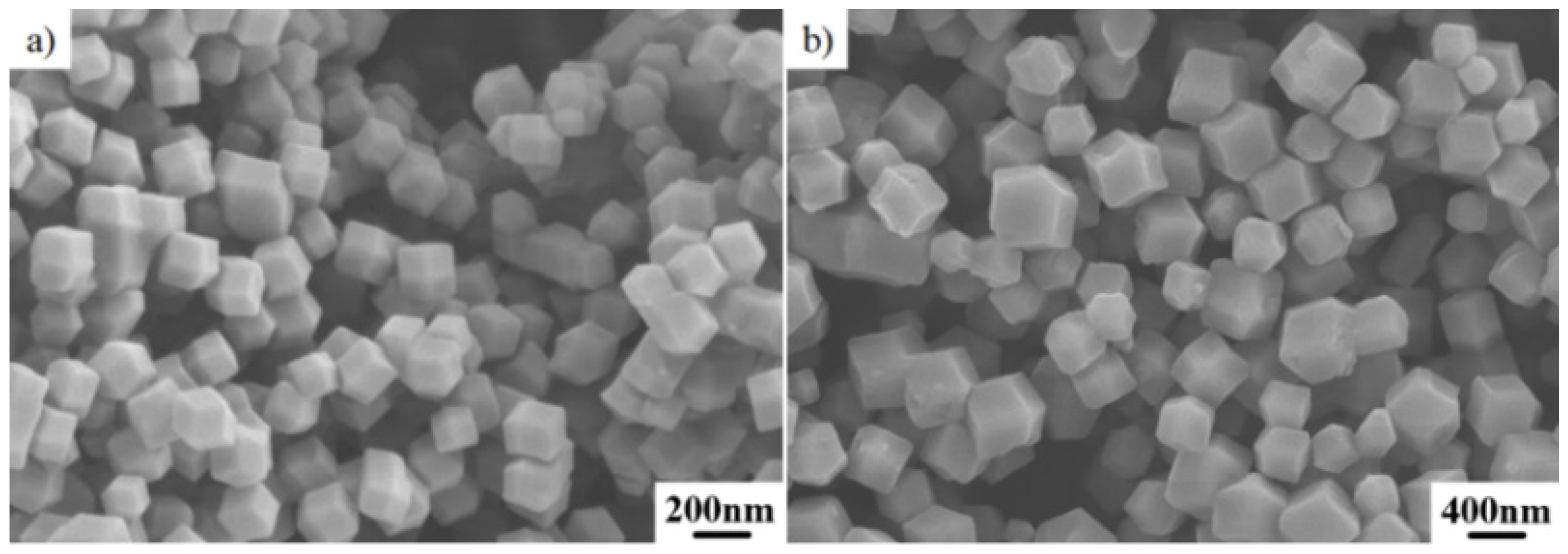
2.1. Initial Co–Doped ZIF–8 Precursor

ZIF–8 materials are formed by the coordination of Zn ions and N–containing 2–methylimidazole organic ligands [17]. The initial morphology of ZIF–8 synthesized using methanol solvent is shown in Figure 1a. It can be seen that ZIF–8 particles exhibit typical uniform, regular rhombic dodecahedron features. The average particle size is about 200 nm. However, ZIF–8 derived catalysts cannot be used directly as ORR catalysts owing to insufficient active sites. By contrast, bimetallic ZIFs derived catalysts exhibit better catalytic activity. The active site can significantly increase by further doping with Co [18,19]. Thus, Co–doped ZIF–8 was synthesized for use as a precursor in the present study. Figure 1b shows the morphology of Co–ZIF–8, which has similar morphology features to that of ZIF–8. However, the average particle size of Co–ZIF–8 can reach up to 400 μm. In order to ensure the exposure of sufficient active sites, Co–doped ZIF–8 precursors need to be pyrolyzed at high–temperature in an argon atmosphere.

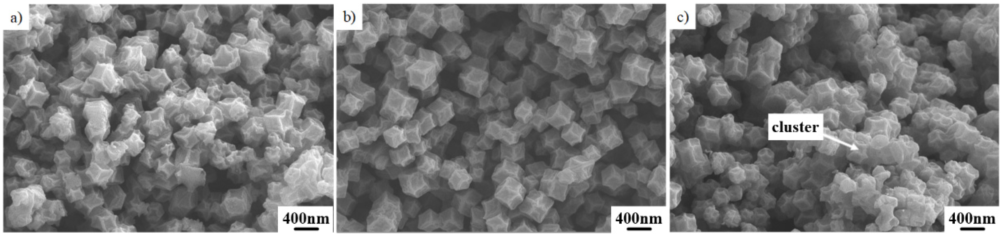
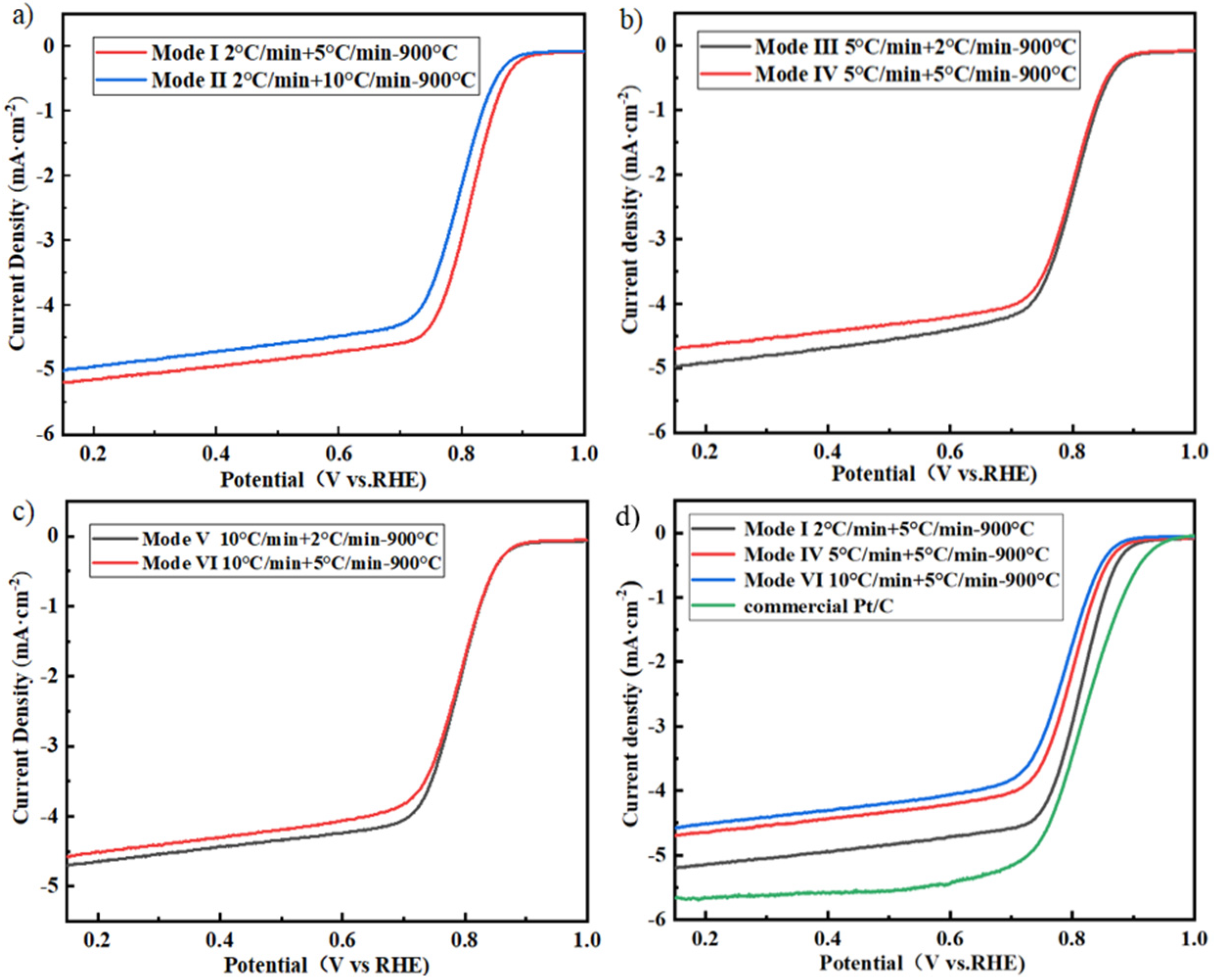
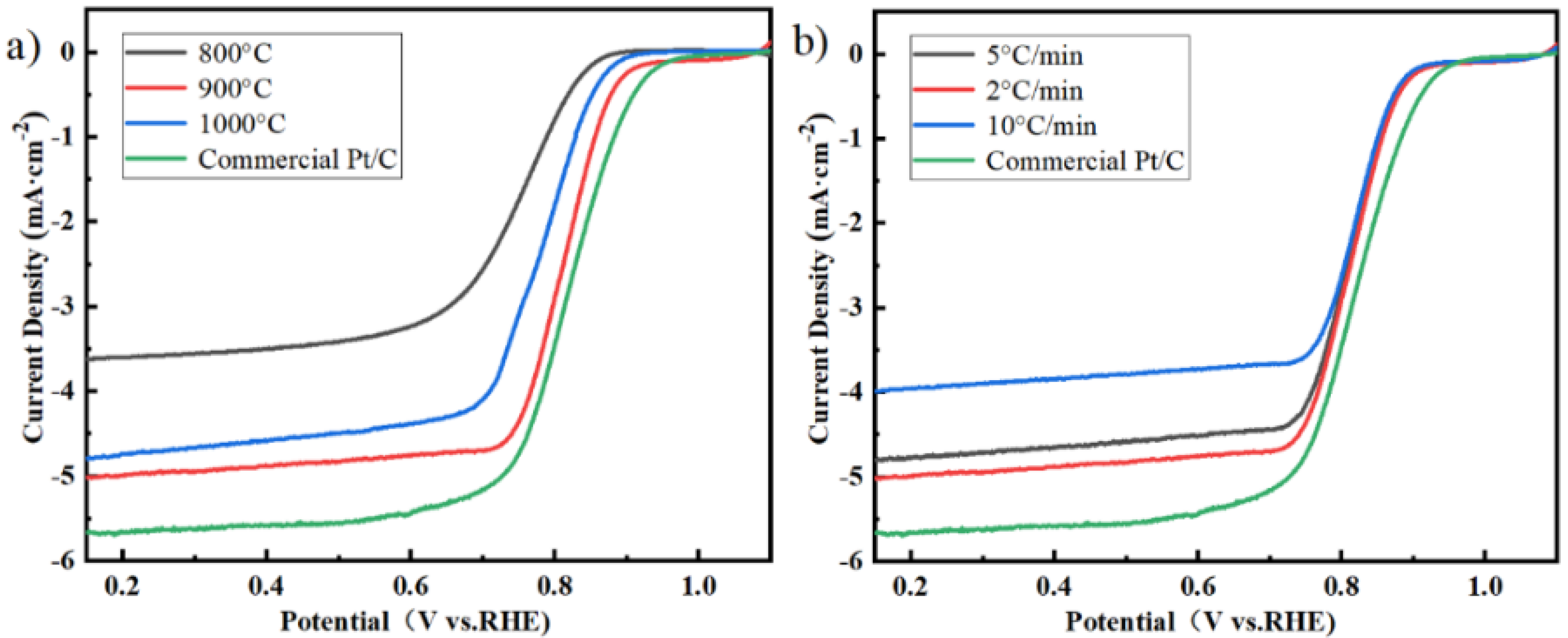
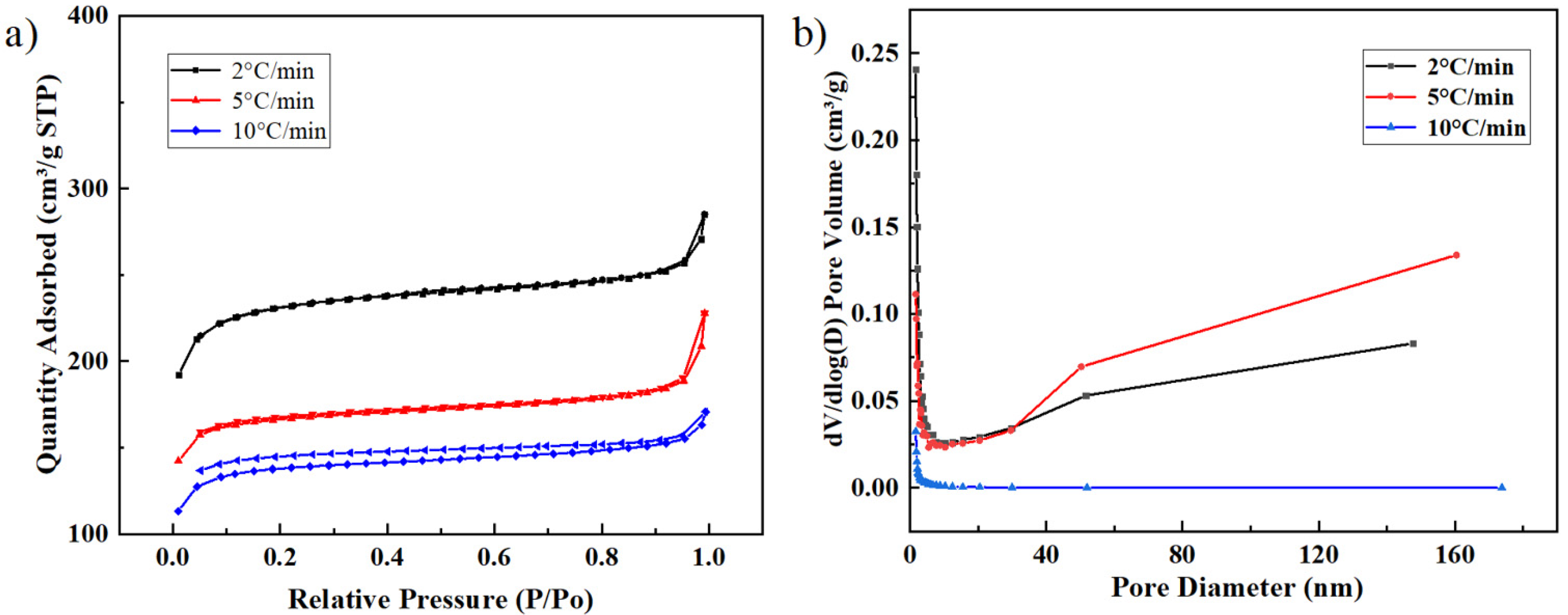
2.2. Effect of Pyrolysis Temperature and Heating Rate on the Catalyst during One–Step Pyrolysis

The pyrolysis of MOF–based materials aims to obtain porous carbon material by the volatilization of metal ions and organic molecules at high temperatures. In order to study the effect of pyrolysis temperature on the catalyst, Co–ZIF–8 precursor was heated to a different temperature (800 °C, 900 °C, and 1000 °C) with a rate of 2 °C/min. Linear sweep voltammetry (LSV) curves of various carbonized Co–ZIF–8 were tested in O2–saturated 0.1 M KOH electrolyte with a scan rate of 10 mV·s−1 and a rotation rate of 1600 rpm. The onset and half–wave potentials of all catalysts were listed in Table 1 in the Experimental section. Moreover, the LSV curve of commercial Pt/C was also tested for comparison. As shown in Figure 2a, commercial Pt/C exhibits high ORR activity with an onset potential of 0.96 VRHE, a half–wave potential of 0.82 VRHE, and a limited current density of 5.7 mA·cm−2. The result is similar to that reported in previous studies [20]. The Co–ZIF–8 carbonized at 800 °C exhibits poor activity with a half–wave potential of 0.74 VRHE and a limited current density of 3.8 mA·cm−2. When the pyrolysis temperature increased to 900 °C, the activity was significantly improved. The half–wave potential and the limited current density increased to 0.80 VRHE and 5.0 mA·cm−2, respectively. When the pyrolysis temperature reached further to 1000 °C, the half–wave potential and the limited current density fell slightly to 0.79 VRHE and 4.89 mA·cm−2, respectively.
A stable carbon framework structure with ordered channel systems is also closely related to the heating rate. To study the effect of heating rate on the performance of catalysts, the Co–ZIF–8 precursor was heated to 900 °C with different heating rates of 2, 5, 10/min. LSV curves of three catalysts were shown in Figure 2b. The catalyst with a heating rate of 10 °C/min exhibits the worst performance with a half–wave potential of 0.77 VRHE and a limited current density of 4.0 mA·cm−2. When the heating rate decreases to 5 °C/min, the half–wave potential and the limited current density increased to 0.78 VRHE and 4.85 mA·cm−2, respectively. With the heating rate further decreases to 2 °C/min, the half–wave potential reached 0.80 VRHE, and. the limited current density reached 5.0 mA·cm−2. It can be seen that the catalytic activity was enhanced with a decrease in the heating rate.
The morphologies of Co–ZIF–8 pyrolyzed at different temperatures were observed by scanning electron microscopy (SEM), as shown in Figure 3a–c. It can be seen that the morphology depends closely on the pyrolysis temperature. Carbonized Co–ZIF–8 particles still remain in initial rhombic dodecahedral shape, but exhibit rough surface and contractive size due to the thermal shrinkage. Despite Co–ZIF–8 particles carbonized at 800 °C (Figure 3a) exhibit contractive morphology. However, the graphitization generally occurs above 800 °C and increases with temperature [21,22]. Low graphitization would lead to low limited current density [23]. In addition, the evaporation of Zn also occurred above 800 °C [24]. Thus, the catalyst carbonized at 800 °C has poor ORR activity. By contrast, Co–ZIF–8 particles carbonized at 900 °C (Figure 3b) exhibit uniform pyrolysis morphology, which corresponds to the best catalytic performance. With the temperature increasing to 1000 °C, some particles are severely agglomerated (Figure 3c). The MN4 (M = Fe and Co) sites are the main active sites [25]. Uniformly dispersed Co atoms contribute to obtaining high–density CoN4 active sites in ZIF–8 [26]. The Co–clustering is detrimental to the ORR catalytic activity. Moreover, the excessive temperature will lead to high Zn content in surface layers due to the evaporation of Zn [22]. Thus, the optimal pyrolysis temperature for Co–ZIF–8 should be 900 °C.
The morphologies of Co–ZIF–8 pyrolyzed at the different heating rates were also observed. As shown in Figure 4a, the catalyst obtained at 10 °C/min has a small amount of carbonized particles and large amounts of bulk phases. It is because that the initial pore structure tends to collapse into bulk phases without significant pores when Zn ions and organic molecules evaporate quickly [15]. When the heating rate decreased to 5 °C/min, the content of bulk phases decreased significantly. Only a tiny amount of bulk phases can be identified, as shown in Figure 4b. As the heating rate further decreased to 2 °C/min, nearly no bulk phases can be observed. The precursor was fully carbonized (Figure 4c).
In order to further study the effect of the heating rate on the carbonized structure, the porosity of catalysts pyrolyzed with different heating rates was analyzed using the Brunauer–Emmet–Teller (BET) method. As shown in Figure 5, Co–ZIF–8 pyrolyzed with a heating rate of 2 °C/min exhibited the highest BET surface area (889 m2/g). The result indicates that lowering the heating rate is conducive to improve the porosity and create a more porous morphology. High porosity can avoid the agglomeration of active sites, thereby enhancing the density of active sites and mass transfer. Moreover, a low heating rate can prolong pyrolysis time and promote the evaporation of unstable species (e.g., Zn and residual organics). Thus, reducing the heating rate is beneficial to enhance the ORR activity of catalysts.

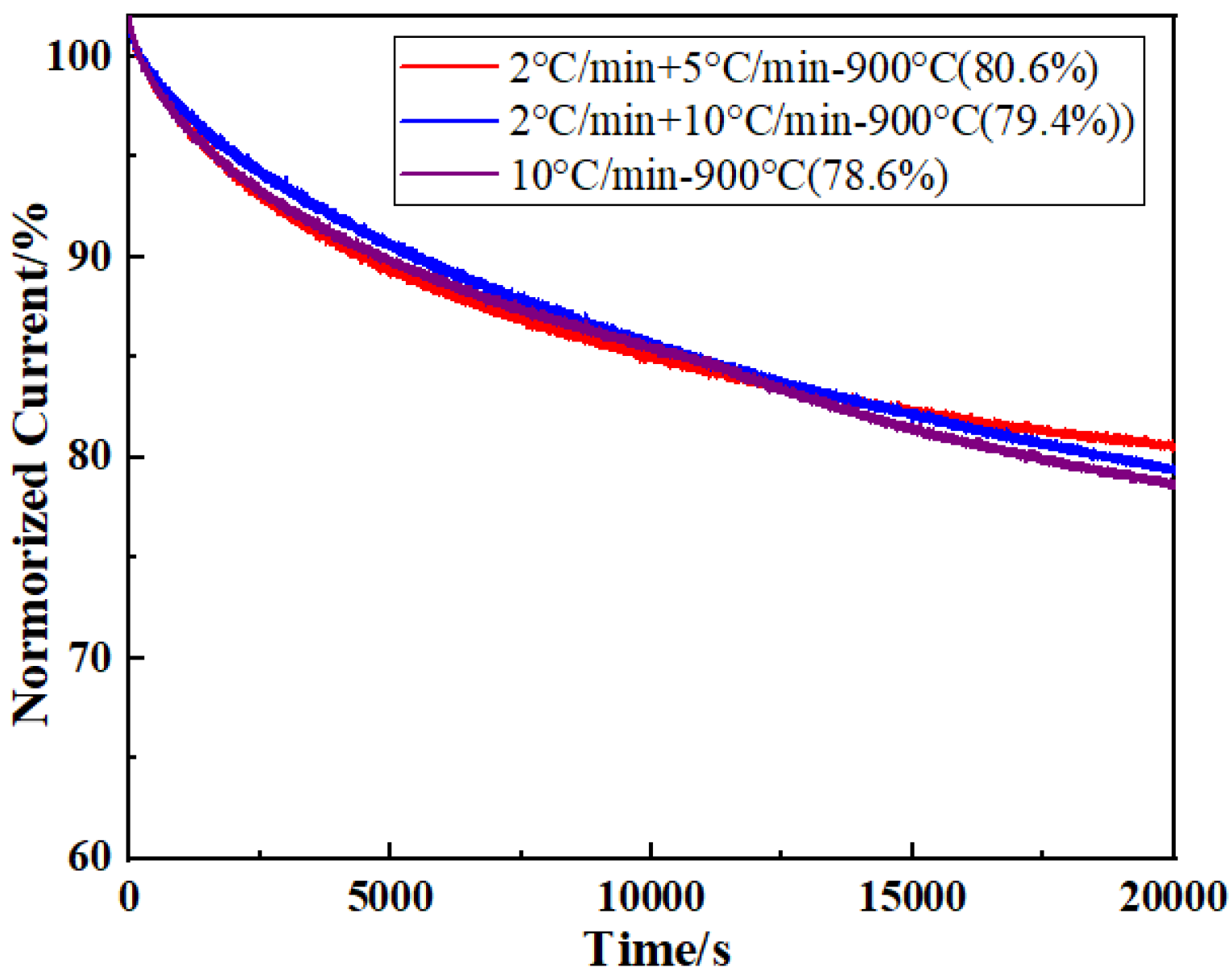
2.3. Effect of Two–Step Pyrolysis on the Performance of the Catalyst

Currently, nearly all studies on MOF–derived catalysts adopt one–step pyrolysis. A few previous studies were also conducted on the two–step pyrolysis process. They mainly investigated the effect of repeated pyrolysis and atmosphere on the ORR activity of catalysts. Ye investigated that the performance of ZIF–8 via two–step pyrolysis in Ar and NH3 atmosphere. First, the initial ZIF–8 was heated to 900 °C in Ar atmosphere. After one–step normal pyrolysis, the catalyst was heated to 900 °C in an Ar atmosphere and kept at 900 °C for 2 h in an NH3 atmosphere [27]. They found that the introduction of NH3 favors mesopore–dominated morphology, which can enhance the ORR activity. Wang also investigated the two–step pyrolysis of a Fe/N/C catalyst. The powder was pyrolyzed at 950 °C in an Ar atmosphere for 1 h. Then the powder was further pyrolyzed at 950 °C for 3 h to obtain final products [28]. Sahraie investigated the effect of three–step pyrolysis on the ORR activity of Fe/N–doped carbon. The first pyrolysis for 1 h and the second and third pyrolysis for 3 h was performed in N2 at 900 °C [29]. However, nearly no study was conducted on the effect of different temperature stages on the catalyst.
The decomposition of ZIF–8 is generally divided into two main stages during pyrolysis [30]. In the low–temperature stage, residual guest molecules and some organics will be removed. In the high–temperature stage, Zn ions and residual organics will evaporate. Thus, a reasonable pyrolysis method is important for the ZIF–derived catalyst. To further study the effect of heating rates at different stages, two–step pyrolysis was employed to prepare Co–ZIF–8 derived catalyst. The Co–ZIF–8 precursor was heated to 350 °C for 1 h with a heating rate of 2, 5, 10 °C/min, and then heated to 900 °C with a heating rate of 2, 5, 10 °C/min. The detailed pyrolysis conditions were listed in Table 1. Corresponding LSV curves were shown in Figure 6. As shown in Figure 6a–c, when the heating rate in the low–temperature stage is a fixed value, the variation of the heating rate in the high–temperature stage has a minor effect on the performance of the catalyst. In contrast, the heating rate in the low–temperature stage has a greater impact, as shown in Figure 6d. When the heating rate in the low temperature reached 10 °C/min (mode Ⅵ), the half–wave potential and the limited current density were just 0.78 VRHE, and 4.7 mA·cm−2, respectively. When the heating rate in the low–temperature stage decreased to 2 °C/min (mode Ⅰ), the catalyst exhibits the best activity with a half–wave potential of 0.82 VRHE and a limited current density of 5.2 mA·cm−2. Thus, a low heating rate in the low–temperature stage can effectively enhance the performance of the catalyst.
Most guest molecules (methanol or H2O) can evaporate easily below 350 °C but some guest molecules in restricted pores are difficult to escape and may be carbonized at high temperatures [31]. These guest molecules need more time to evaporate. A slow heating rate can promote the evaporation of these guest molecules. Moreover, a large amount of organic molecules can evaporate below 350 °C. Reducing the evaporation rate is conducive to the even shrinkage of materials, thereby avoiding the collapse of pores. A stable carbon–based skeleton can be gradually formed. After the formation of the stable carbon–based skeletons, a modest increase in the heating rate is feasible in the high–temperature stage. However, it also should be noted that the excessive heating rate is also not suitable. The excessive heating rate can accelerate the volatilization of Zn ions and residual organics. Co, C, and N atoms may not be connected well enough. Thus, the heating rate in the first stage should be low. Moreover, it can be found from Figure 2a and Figure 6d that the performance of the catalyst obtained by two–step pyrolysis mode Ⅰ is slightly higher than that of the catalyst obtained by one–step pyrolysis with a heating rate of 2 °C/min. It should benefit from the heat preservation at 350 °C, which strengthens the carbon skeleton. To sum up, the optimal pyrolysis condition should be mode Ⅰ.

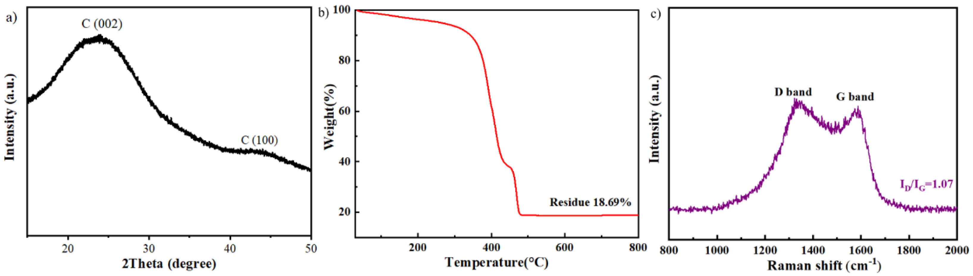
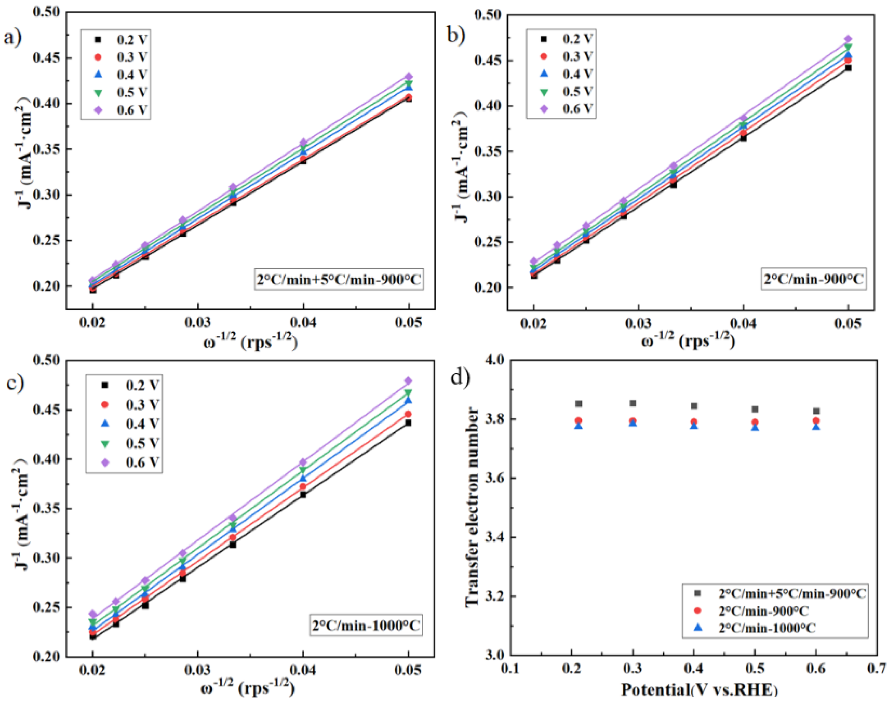
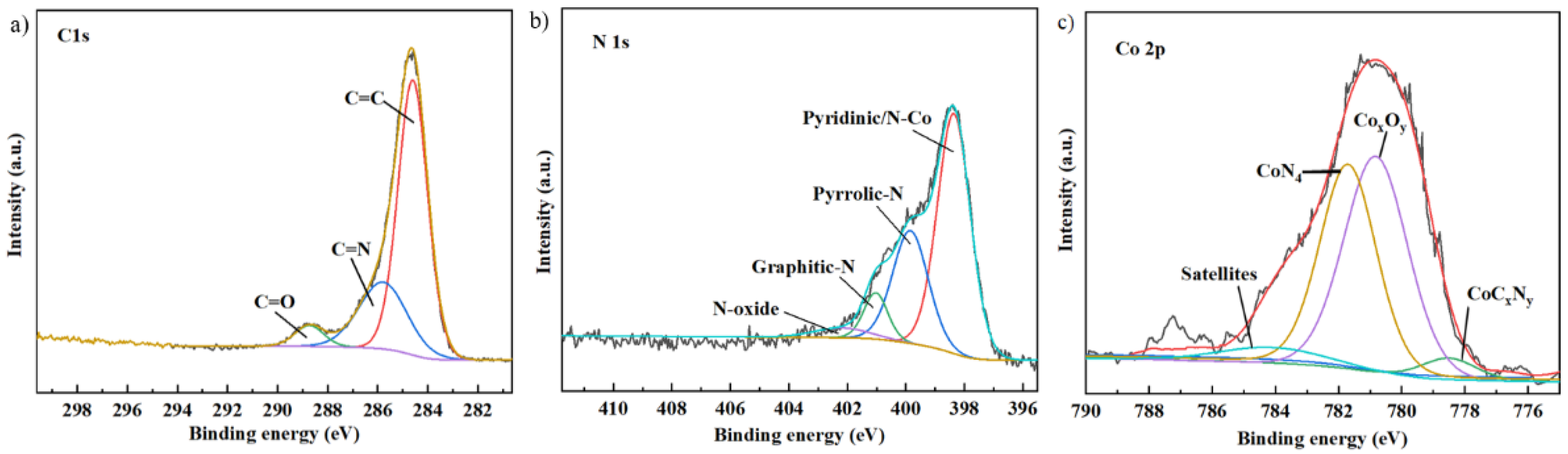
2.4. The Description of the Catalyst Carbonized at the Optimum Pyrolysis Condition

The Co–ZIF–8 catalyst pyrolyzed at the optimal condition (mode Ⅰ) was further analyzed. Figure 7a shows the X-ray diffraction (XRD) pattern for the optimum Co–ZIF–8 catalyst. The pattern shows two main peaks at 25° and 44°, which correspond to (002) and (101) diffractions of the graphitic carbon. It indicates that the Co–ZIF–8 precursor was well–carbonized. Considering that Co atoms may be capsuled in graphitized carbon, the content of Co atoms in the catalyst was further analyzed by thermal gravimetric analysis (TGA), as shown in Figure 7b. There were 18.69 wt% of weight remained up to 800 °C in air atmosphere. The residue loading is Co3O4 [32]. Thus, the Co content is estimated to be about 13.7 wt%. Raman spectrum was also performed to investigate the carbonaceous structure of the catalyst (Figure 7c). It can be seen from the spectrum that two characteristic peaks D and G appear at around 1350 and 1580 cm−1. The intensity ratio of the D band to the G band (ID/IG) can be used to describe the graphitization degree and the defect number of carbon materials. By calculating, the ID/IG value of the sample is 1.07, indicating that the sample exhibits high content of defects, which can provide a large amount of active sites, thereby improving the ORR catalytic activity [33]. Moreover, the porosity of the catalyst carbonized by mode Ⅰ was measured by BET. The catalyst exhibits a BET surface area of 1122 m2/g.
The Co–ZIF–8 catalyst carbonized by mode Ⅰ was analyzed by transmission electron microscopy (TEM). It can be seen from Figure 8a,b that the catalyst still retains the polyhedral structure feature of the initial precursor. Previous studies show that some particles enriched doping atoms may form due to excessive doping atoms or too rapid a heating rate, which will affect the catalytic activity [34]. However, no significant particles enriched with Co can be observed in the image with high magnification (Figure 8c), indicating that Co atoms are highly dispersed in the catalyst. It can also be observed that pore–like morphologies are the main features of the Co–ZIF–8 catalyst. Moreover, TEM mapping was conducted to analyze the element distribution, as shown in Figure 8d,e. It is further confirmed that Co and N atoms are highly dispersed in the catalyst, which is conducive to the exposure of more active sites.
The element composition of the catalyst was analyzed by X-ray photoelectron spectroscopy (XPS). The C1s spectra (Figure 9a) shows two peaks at 284.6 eV, 285.79 eV, and 288.73 ev, corresponding to the binding energy of C=C, C=N, and C=O, respectively. The N1s XPS spectra (Figure 9b) shows N exists in four states: pyridine N and N–Co (398.4 eV), pyrrole N (399.92 eV), graphite N (401 eV), and N–oxide (402.14 eV). It should be noted that further deconvolution is difficult for pyridine N and N–Co due to their similar binding energy [35]. From the peak intensity, most of N exists in the form of pyridine N, N–Co, and graphite N, which are the main electrocatalytic active sites for ORR [36,37,38]. The XPS spectra (Figure 9c) shows a Co 2p3/2 peak at 781.3 eV [39]. It further indicates that N–Co bonding generally exists in the form of CoN4.
The electron transfer number (n) of Co–ZIF–8 during ORR was also measured. We also compared the n values of catalysts pyrolyzed at different conditions. As shown in Figure 10, the results of Koutecky–Levich (KL) plots show the average n values of Co–ZIF–8 pyrolyzed at the conditions of 2 °C/min + 5 °C/min–900 °C, 2 °C/min–900 °C, 2 °C/min–1000 °C were 3.84, 3.79, and 3.77, respectively. This confirmed that the ORR on different Co–ZIF–8 mainly followed a four–electron process. However, the pyrolysis condition also has a certain effect on the electron transfer number. Combined with porosity analysis, the porosity can be improved by optimizing pyrolysis conditions. As the porosity increased, the transferred number of electrons tends to be closer to four.
The stability of the Co–ZIF–8 catalyst was tested by chronoamperometry at a relatively high potential of 0.7 V in O2–saturated 0.1 M KOH. It can be seen from Figure 11 that Co–ZIF–8 pyrolyzed at the condition of 2 °C/min + 5 °C/min–900 °C retained 81% of its initial ORR performance after 20,000 s. The stability is close to that of Co–ZIF–8 obtained at other pyrolysis conditions [22]. It illustrates that the cyclic stability mostly depends on the catalyst’s own characteristics. Carbon corrosion and dissolution of metal sites may be the main reason for the low stability [22,40]. The pyrolysis condition has little effect on the cyclic stability.

3. Materials and Methods

3.1. Materials and Equipment

Zn(NO3)2·6H2O and KOH were supplied by Sinopharm Group. Co(NO3)2·6H2O, 2–methylimidazole, methanol, and isopropanol were purchased from Shanghai Macklin Biochemical (Shanghai, China). Pt/C catalyst (20 wt% Pt) was obtained from Johnson Matthey Chemicals. Vulcan XC–72 carbon was supplied by Cabot Chemical. A 5% Nafion solution was acquired from Sigma–Aldrich. All chemicals were of analytical grade, and no additional purification is required.
Linear sweep voltammetry curves were tested using electrochemical workstation (CHI 660A, Shanghai, China) and a rotating disk electrode (RDE, Pine, Grove city, PA, USA) in O2–saturated 0.1 M KOH solution. RED, silver–chloride electrode, and graphite electrode were used as working electrode, reference electrode and counter electrode, respectively. A catalyst ink was prepared by ultrasonically dispersing 5 mg catalyst in 300 μL deionized water, 700 μL Isopropanol and 10 μL Nafion solution (5 wt%). The obtained 10 μL of catalyst ink was spread on the RDE electrode and dried. The catalyst loading was approximately 0.232 mg·cm−2. The Co content in the catalyst was measured by TGA (STA449F5, Netzsch, Bavaria, Germany). The porosity of the catalyst was tested by BET (ASAP 2460, Micromeritics, Norcross, GE, USA). The morphology of various catalysts was observed using SEM (Merlin Compact, Carl Zeiss, Heidenheim, Germany). The enlarged morphology and elemental mapping were obtained using TEM (JEM–2100, JEOL, Tokyo, Japan). The Roman spectrum was measured by Raman spectroscopy (inVia, Renishaw, London, UK). Component analyses were carried out by XPS (EscaLab Xi+, Thermo Fisher, Waltham, MA, USA).

3.2. The Synthesis of Co–ZIF–8 Precursor

The Co–ZIF–8 precursor was synthesized by conventional hydrothermal method. Zn(NO3)2·6H2O (1.488 g) and Co(NO3)2·6H2O (0.364 g) were dissolved in 50 mL methanol (named solution A). A total of 2–methylimidazole (1.642 g) was dissolved in 50 mL methanol (named solution B). The solution A and B were stirred for 5 min, respectively. Then the solution A was poured into solution B. The mixed solution was stirred for 10 min. Pouring the mixed solution into the centrifuge tube and let stand for 24 h. The obtained precipitation was centrifuged at a rate of 7000 rpm for 2 min and then washed with methanol/ethanol 5 times. The precipitation was placed in a vacuum drying oven and heated to 80 °C for 24 h. Finally, Co–ZIF–8 powders with light purple were obtained.

3.3. The Pyrolysis of Co–ZIF–8 Precursor

The Co–ZIF–8 precursor was placed in a tube furnace and then carbonized in an argon atmosphere according to pre–set pyrolysis conditions. In order to study the effect of pyrolysis conditions on the performance of catalysts, different heating modes, heating rates, and carbonization temperature were adopted, as shown in Table 1. The onset and half–wave potentials of all the catalysts were also listed in the table.

4. Conclusions

In this study, the effect of pyrolysis conditions on the performance of Co–doped ZIF–derived catalysts was systematically investigated. The main conclusions from this work are as follows:
(1) The catalytic activity depends closely on the temperature and heating rate. The Co–ZIF–8 catalyst carbonized at 900 °C exhibits better ORR catalytic activity. A low heating rate can enhance the catalytic activity.
(2) Two–step pyrolysis is an effective way to improve the performance of catalysts. Reducing the heating rate in the low–temperature stage is more beneficial to the ORR performance, compared to the heating rate in the high–temperature stage.
(3) The Co–ZIF–8 catalyst exhibits the best ORR performance when the precursor was heated to 350 °C for 1 h at 2 °C/min, and then heated to 900 °C at 5 °C/min. The half–wave potential and the current density can reach 0.82 V and 5.2 mA·cm−2 in 0.1 M KOH solution. Co and N atoms are also highly dispersed in the carbon skeleton. However, the stability of the catalyst cannot be improved significantly by two–step pyrolysis.

Author Contributions

Conceptualization, N.C.; Methodology, K.B.; Software, N.C.; Validation, N.C.; Formal Analysis, N.C.; Investigation, K.B.; Resources, N.C.; Data Curation, K.B.; Writing—Original Draft Preparation, N.C., Q.W.; Writing—Review and Editing, S.Z.; Visualization, N.C.; Supervision, B.L., W.S., Y.L.; Project Administration, T.X.; Funding Acquisition, N.C., Q.W. All authors have read and agreed to the published version of the manuscript.

Funding

Please add: This research was funded by the open problem of Innovation Institute for Sustainable Maritime Architecture Research and Technology (Qingdao University of Technology), the Shandong Province Key Research and Development Program (2019GGX102045), and the National Natural Science Foundation of China (51905288, 51704174).

Conflicts of Interest

The authors declare no conflict of interest. The funders had no role in the design of the study; in the collection, analyses, or interpretation of data; in the writing of the manuscript, and in the decision to publish the results.

References

  1. Zhang, J.; Sasaki, K.; Sutter, E.; Adzic, R. Stabilization of platinum oxygen–reduction electrocatalysts using gold clusters. Science 2007, 315, 220–222. [Google Scholar] [CrossRef] [Green Version]
  2. Rosli, R.E.; Sulong, A.B.; Daud, W.R.W.; Zulkifley, M.A.; Husaini, T.; Rosli, M.I.; Majlan, E.H.; Haque, M.A. A review of high–temperature proton exchange membrane fuel cell (HT–PEMFC) system. Int. J. Hydrogen Energy 2017, 42, 9293–9314. [Google Scholar] [CrossRef]
  3. Devanathan, R. Recent developments in proton exchange membranes for fuel cells. Energy Environ. Sci. 2008, 1, 101–119. [Google Scholar] [CrossRef]
  4. Zhu, C.; He, L.; Fu, S.; Dan, D.; Lin, Y. Highly efficient nonprecious metal catalysts towards oxygen reduction reaction based on three–dimensional porous carbon nanostructures. Chem. Soc. Rev. 2016, 45, 517–531. [Google Scholar] [CrossRef]
  5. Wang, D.; Astruc, D. The recent development of efficient Earth–abundant transition–metal nanocatalysts. Chem. Soc. Rev. 2017, 46. [Google Scholar] [CrossRef] [PubMed]
  6. Ren, Q.; Wang, H.; Lu, X.-F.; Tong, Y.-X.; Li, G.-R. Recent Progress on MOF–Derived Heteroatom–Doped Carbon–Based Electrocatalysts for Oxygen Reduction Reaction. Adv. Sci. 2018, 5, 1700515. [Google Scholar] [CrossRef] [PubMed] [Green Version]
  7. Rosi, N.; Eckert, J.; Eddaoudi, M.; Vodak, D.; Kim, J.; O’Keeffe, M.; Yaghi, O. Hydrogen Storage in Microporous Metal–Organic Frameworks. Science 2003, 300, 1127–1129. [Google Scholar] [CrossRef] [PubMed] [Green Version]
  8. Eddaoudi, M.; Kim, J.; Rosi, N.; Vodak, D.; Wachter, J.; O’Keeffe, M.; Yaghi, O. Systematic Design of Pore Size and Functionality in Isoreticular MOFs and Their Application in Methane Storage. Science 2002, 295, 469–472. [Google Scholar] [CrossRef] [Green Version]
  9. Li, J.; Sculley, J.; Zhou, H. Metal–Organic Frameworks for Separations. Chem. Rev. 2012, 112, 869–932. [Google Scholar] [CrossRef] [PubMed]
  10. Anwar, R.; Iqbal, N.; Hanif, S.; Noor, T.; Shi, X.; Zaman, N.; Haider, D.; Rizvi, S.A.M.; Kannan, A.M. MOF–Derived CuPt/NC Electrocatalyst for Oxygen Reduction Reaction. Catalysts 2020, 10, 799. [Google Scholar] [CrossRef]
  11. Shaik, G.P.; Kwon, H.-J.; Lee, T.G. Highly efficient Co@NCS nanosheet electrocatalyst for oxygen reduction reaction: An environment–friendly, low–cost and sustainable electrocatalyst. Mater. Res. Bull. 2020, 128, 110873. [Google Scholar] [CrossRef]
  12. Zhao, D.; Shui, J.-L.; Grabstanowicz, L.; Chen, C.; Commet, S.; Lu, J.; Liu, D.-J. Highly Efficient Non-Precious Metal Electrocatalysts Prepared from One-Pot Synthesized Zeolitic Imidazolate Frameworks. Adv. Mater. 2014, 26, 1093–1097. [Google Scholar] [CrossRef] [PubMed]
  13. Zhang, J.-P.; Zhang, Y.-B.; Lin, J.-B.; Chen, X.-M. Metal Azolate Frameworks: From Crystal Engineering to Functional Materials. Chem. Rev. 2012, 112, 1001–1033. [Google Scholar] [CrossRef] [PubMed]
  14. Gao, C.; Jiang, Z.; Wang, P.; Jensen, L.; Zhang, Y.; Yue, Y. Metal-Organic Framework Glass Anode with an Exceptional Cycling-Induced Capacity Enhancement for Lithium Ion Batteries. Energy 2021. [CrossRef]
  15. Kong, L.; Xie, C.-C.; Gu, H.; Wang, C.-P.; Zhou, X.; Liu, J.; Zhou, Z.; Li, Z.-Y.; Zhu, J.; Bu, X.-H. Thermal Instability Induced Oriented 2D Pores for Enhanced Sodium Storage. Small 2018, 14, 1800639. [Google Scholar] [CrossRef]
  16. Zhang, X.; Chen, Z.; Liu, X.; Hanna, S.; Wang, X.; Taheri-Ledari, R.; Maleki, A.; Farha, O. A historical overview of the activation and porosity of metal-organic frameworks. Chem. Soc. Rev. 2020, 49. [Google Scholar] [CrossRef]
  17. Huang, X.-C.; Lin, Y.-Y.; Zhang, J.-P.; Chen, X.-M. Ligand-Directed Strategy for Zeolite-Type Metal–Organic Frameworks: Zinc(II) Imidazolates with Unusual Zeolitic Topologies. Angew. Chem. 2006, 45, 1557–1559. [Google Scholar] [CrossRef]
  18. Lee, J.S.; Park, G.S.; Kim, S.T.; Liu, M.; Cho, J. A Highly Efficient Electrocatalyst for the Oxygen Reduction Reaction: N-Doped Ketjenblack Incorporated into Fe/Fe3C-Functionalized Melamine Foam. Angew. Chem. 2013, 52, 1026–1030. [Google Scholar] [CrossRef]
  19. Kramm, U.; Lefèvre, M.; Bogdanoff, P.; Schmeißer, D.; Dodelet, J.-P. Analyzing Structural Changes of Fe–N–C Cathode Catalysts in PEM Fuel Cell by Mößbauer Spectroscopy of Complete Membrane Electrode Assemblies. J. Phys. Chem. Lett. 2014, 5, 3750–3756. [Google Scholar] [CrossRef]
  20. Hu, L.; Yu, F.; Wang, F.; Yang, S.; Peng, B.; Chen, L.; Wang, G.; Hou, J.; Dai, B.; Tian, Z.-Q. Overwhelming electrochemical oxygen reduction reaction of zinc-nitrogen-carbon from biomass resource chitosan via a facile carbon bath method. Chin. Chem. Lett. 2020, 31, 1207–1212. [Google Scholar] [CrossRef]
  21. Li, X.; Zhang, B.; Fang, Y.; Sun, W.; Qi, Z.; Pei, Y.; Qi, S.; Yuan, P.; Luan, X.; Goh, T.W.; et al. Metal-Organic Framework Derived Carbons: Applications as Solid Base Catalyst and Support for Pd Nanoparticles in Tandem Catalysis. Chem. Eur. J. 2017, 23. [Google Scholar] [CrossRef] [PubMed] [Green Version]
  22. Wang, X.; Cullen, D.; Pan, Y.-T.; Hwang, S.; Wang, M.; Feng, Z.; Wang, J.; Engelhard, M.; Zhang, H.; He, Y.; et al. Nitrogen-Coordinated Single Cobalt Atom Catalysts for Oxygen Reduction in Proton Exchange Membrane Fuel Cells. Adv. Mater. 2018, 30, 1706758. [Google Scholar] [CrossRef] [PubMed]
  23. Qiao, M.; Wang, Y.; Wang, Q.; Hu, G.; Mamat, X.; Zhang, S.; Wang, S. Hierarchically Ordered Porous Carbon with Atomically Dispersed FeN4 for Ultraefficient Oxygen Reduction Reaction in Proton-Exchange Membrane Fuel Cells. Angew. Chem. Int. Ed. 2020, 59, 2688–2694. [Google Scholar] [CrossRef] [PubMed]
  24. Yin, P.Q.; Yao, T.; Wu, Y.; Zheng, L.R.; Lin, Y.; Liu, W.; Ju, H.X.; Zhu, J.F.; Hong, X.; Deng, Z.X.; et al. Single Cobalt Atoms with Precise N-Coordination as Superior Oxygen Reduction Reaction Catalysts. Angew. Chem. Int. Ed. 2016, 55, 10800–10805. [Google Scholar] [CrossRef] [PubMed]
  25. Zitolo, A.; Ranjbar-Sahraie, N.; Mineva, T.; Li, J.; Jia, Q.; Stamatin, S.; Harrington, G.; Lyth, S.; Krtil, P.; Mukerjee, S.; et al. Identification of catalytic sites in cobalt-nitrogen-carbon materials for the oxygen reduction reaction. Nat. Commun. 2017, 8. [Google Scholar] [CrossRef] [PubMed]
  26. Li, J.Z.; Chen, M.J.; Cullen, D.A.; Hwang, S.; Wang, M.Y.; Li, B.Y.; Liu, K.X.; Karakalos, S.; Lucero, M.; Zhang, H.G.; et al. Atomically dispersed manganese catalysts for oxygen reduction in proton-exchange membrane fuel cells. Nat. Catal. 2018, 1, 935–945. [Google Scholar] [CrossRef]
  27. Ye, Y.F.; Cai, F.; Yan, C.C.; Li, Y.S.; Wang, G.X.; Bao, X.H. Two-step pyrolysis of ZIF-8 functionalized with ammonium ferric citrate for efficient oxygen reduction reaction. J. Energy Chem. 2017, 26, 1174–1180. [Google Scholar] [CrossRef] [Green Version]
  28. Wang, Y.; Lai, Y.J.; Song, L.; Zhou, Z.Y.; Liu, J.G.; Wang, Q.; Yang, X.D.; Chen, C.; Shi, W.; Zheng, Y.P.; et al. S-Doping of an Fe/N/C ORR Catalyst for Polymer Electrolyte Membrane Fuel Cells with High Power Density. Angew. Chem. 2015, 54. [Google Scholar] [CrossRef]
  29. Sahraie, N.; Kramm, U.; Steinberg, J.; Zhang, Y.; Thomas, A.; Reier, T.; Paraknowitsch, J.P.; Strasser, P. Quantifying the density and utilization of active sites in non-precious metal oxygen electroreduction catalysts. Nat. Commun. 2015, 6, 8618–8626. [Google Scholar] [CrossRef] [Green Version]
  30. Zhou, K.; Mousavi, B.; Luo, Z.; Phatanasri, S.; Chaemchuen, S.; Verpoort, F. Characterization and properties of Zn/Co zeolitic imidazolate frameworks vs. ZIF-8 and ZIF-67. J. Mater. Chem. A 2017, 5, 952–957. [Google Scholar] [CrossRef]
  31. Park, K.; Ni, Z.; Côté, A.; Choi, J.; Huang, R.; Uribe-Romo, F.; Chae, H.; O’Keeffe, M.; Yaghi, O. Exceptional Chemical and Thermal Stability of Zeolitic Imidazolate Frameworks. Proc. Natl. Acad. Sci. USA 2006, 103, 10186–10191. [Google Scholar] [CrossRef] [Green Version]
  32. Song, A.; Yang, W.; Yang, W.; Sun, G.; Yin, X.; Gao, L.; Wang, Y.; Qin, X.; Shao, G. Facile Synthesis of Cobalt Nanoparticles Entirely Encapsulated in Slim Nitrogen-Doped Carbon Nanotubes as Oxygen Reduction Catalyst. ACS Sustain. Chem. Eng. 2017, 5, 3973–3981. [Google Scholar] [CrossRef]
  33. Yang, L.; Zeng, X.; Wang, W.; Cao, D. Recent Progress in MOF-Derived, Heteroatom-Doped Porous Carbons as Highly Efficient Electrocatalysts for Oxygen Reduction Reaction in Fuel Cells. Adv. Funct. Mater. 2018, 28. [Google Scholar] [CrossRef]
  34. Deng, Y.; Dong, Y.; Wang, G.; Sun, K.; Shi, X.; Zheng, L.; Li, X.; Liao, S. Well-Defined ZIF-Derived Fe-N Codoped Carbon Nanoframes as Efficient Oxygen Reduction Catalysts. ACS Appl. Mater. Interfaces 2017, 9, 9699–9709. [Google Scholar] [CrossRef]
  35. Fei, H.; Dong, J.; Arellano-Jiménez, M.J.; Ye, G.; Dong Kim, N.; Samuel, E.L.G.; Peng, Z.; Zhu, Z.; Qin, F.; Bao, J.; et al. Atomic cobalt on nitrogen-doped graphene for hydrogen generation. Nat. Commun. 2015, 6, 8668. [Google Scholar] [CrossRef]
  36. Cui, X.; Yang, S.; Yan, X.; Leng, J.; Shuang, S.; Ajayan, P.M.; Zhang, Z. Pyridinic-Nitrogen-Dominated Graphene Aerogels with Fe–N–C Coordination for Highly Efficient Oxygen Reduction Reaction. Adv. Funct. Mater. 2016, 26, 5708–5717. [Google Scholar] [CrossRef]
  37. Lai, L.; Potts, J.R.; Zhan, D.; Wang, L.; Poh, C.K.; Tang, C.; Gong, H.; Shen, Z.; Lin, J.; Ruoff, R.S. Exploration of the active center structure of nitrogen-doped graphene-based catalysts for oxygen reduction reaction. Energy Environ. Sci. 2012, 5, 7936–7942. [Google Scholar] [CrossRef]
  38. Jiang, M.; Cao, X.; Liu, P.; Zhang, T.; Zhang, J. ZIF-8@Polyvinylpyrrolidone Nanocomposites Based N-Doped Porous Carbon for Highly Efficient Oxygen Reduction Reaction in Alkaline Solution. J. Electrochem. Soc. 2016, 163, H459–H464. [Google Scholar] [CrossRef]
  39. Chao, S.; Bai, Z.; Cui, Q.; Yan, H.; Wang, K.; Yang, L. Hollowed-out octahedral Co/N-codoped carbon as a highly efficient non-precious metal catalyst for oxygen reduction reaction. Carbon 2015, 82, 77–86. [Google Scholar] [CrossRef]
  40. Ferrandon, M.; Wang, X.; Kropf, A.; Myers, D.; Wu, G.; Johnston, C.; Zelenay, P. Stability of iron species in heat-treated polyaniline–iron–carbon polymer electrolyte fuel cell cathode catalysts. Electrochim. Acta 2013, 110, 282–291. [Google Scholar] [CrossRef]
Figure 1. (a) The initial morphology of ZIF–8, (b) The initial morphology of Co–ZIF–8.
Catalysts 11 01163 g001
Figure 2. (a) LSV curves of Co–ZIF–8 pyrolyzed at different temperatures, (b) LSV curves of Co–ZIF–8 pyrolyzed at heating rates.
Catalysts 11 01163 g002
Figure 3. (a) The microstructure of Co–ZIF–8 pyrolyzed at 800 °C, (b) The microstructure of Co–ZIF–8 pyrolyzed at 900 °C, (c) The microstructure of Co–ZIF–8 pyrolyzed at 1000 °C.
Catalysts 11 01163 g003
Figure 4. (a) The microstructure of Co-ZIF–8 pyrolyzed with a heating rate of 10 °C/min; (b) The microstructure of Co-ZIF–8 pyrolyzed with a heating rate of 5 °C/min; (c) The microstructure of Co-ZIF–8 pyrolyzed with a heating rate of 2 °C/min.
Catalysts 11 01163 g004
Figure 5. (a) N2 adsorption and desorption isotherms of Co–ZIF–8, (b) pore–size distributions of Co–ZIF–8.
Catalysts 11 01163 g005
Figure 6. (a) LSV curves of Co–ZIF–8 pyrolyzed with a heating rate of 2 °C/min in the first stage; (b) LSV curves of Co–ZIF–8 pyrolyzed with a heating rate of 5 °C/min in the first stage; (c) LSV curves of Co–ZIF–8 pyrolyzed with a heating rate of 10 °C/min in the first stage; (d) LSV curves of Co–ZIF–8 pyrolyzed with a heating rate of 5 °C/min in the second stage.
Catalysts 11 01163 g006
Figure 7. (a) XRD pattern of the Co–ZIF–8 catalyst; (b) TGA curve of the Co–ZIF–8 catalyst; (c) Raman spectrum of the Co–ZIF–8 catalyst.
Catalysts 11 01163 g007
Figure 8. (ac) TEM images showing the morphology of the Co–ZIF–8 catalyst, (df) TEM mapping showing the distribution of Co, N, C elements.
Catalysts 11 01163 g008
Figure 9. XPS spectra of the catalyst carbonized at the optimum pyrolysis condition (a) C1s, (b) N1s, (c) Co 2p.
Catalysts 11 01163 g009
Figure 10. (a) K–L plots of Co–ZIF–8 pyrolyzed at 2 °C/min + 5 °C/min–900 °C; (b) K–L plots of Co–ZIF–8 pyrolyzed at 2 °C/min–900 °C; (c) K–L plots of Co–ZIF–8 pyrolyzed at 2 °C/min–1000 °C, (d) Transferred electron numbers at different potentials.
Catalysts 11 01163 g010
Figure 11. The stability of the Co–ZIF–8 catalyst at 0.7 V in O2–saturated 0.1 M KOH.
Catalysts 11 01163 g011
Table 1. The pyrolysis conditions and performance of the Co–ZIF–8 precursor.
Heating ModeRate
(°C/min)
Time
(h)
Temperature (°C)Rate
(°C/min)
Temperature (°C)Time
(h)
Onset Potentials (VRHE)Half–Wave Potentials (VRHE)
One–step
pyrolysis
280020.860.74
290020.970.80
2100020.890.79
590020.950.78
1090020.940.77
Two–step
pyrolysis
21 h350590020.980.82
21 h3501090020.920.79
51 h350290020.930.78
51 h350590020.920.78
101 h350290020.900.77
101 h350590020.890.76
Publisher’s Note: MDPI stays neutral with regard to jurisdictional claims in published maps and institutional affiliations.

