Article

H2 Production from Catalytic Methane Decomposition Using Fe/x-ZrO2 and Fe-Ni/(x-ZrO2) (x = 0, La2O3, WO3) Catalysts

by
Fahad Al-Mubaddel
1,2,
Samsudeen Kasim
1,
Ahmed A. Ibrahim
1,
Abdulrhman S. Al-Awadi
1,
Anis H. Fakeeha
1,2 and
Ahmed S. Al-Fatesh
1,*
1
Chemical Engineering Department, College of Engineering, King Saud University, P.O. Box 800, Riyadh 11421, Saudi Arabia
2
King Abdullah City for Atomic & Renewable Energy, Energy Research & Innovation Center (ERIC) in Riyadh, Riyadh 11451 Saudi Arabia
*
Author to whom correspondence should be addressed.
Catalysts 2020, 10(7), 793; https://doi.org/10.3390/catal10070793
Submission received: 8 June 2020 / Revised: 10 July 2020 / Accepted: 13 July 2020 / Published: 16 July 2020

Abstract

:
An environmentally-benign way of producing hydrogen is methane decomposition. This study focused on methane decomposition using Fe and Fe-Ni catalysts, which were dispersed over different supports by the wet-impregnation method. We observed the effect of modifying ZrO2 with La2O3 and WO3 in terms of H2 yield and carbon deposits. The modification led to a higher H2 yield in all cases and WO3-modified support gave the highest yield of about 90% and was stable throughout the reaction period. The reaction conditions were at 1 atm, 800 °C, and 4000 mL(hgcat)−1 space velocity. Adding Ni to Fe/x-ZrO2 gave a higher H2 yield and stability for ZrO2 and La2O3 + ZrO2-supported catalysts whose prior performances and stabilities were very poor. Catalyst samples were analyzed by characterization techniques like X-ray diffraction (XRD), nitrogen physisorption, temperature-programmed reduction (TPR), thermo-gravimetric analysis (TGA), and Raman spectroscopy. The phases of iron and the supports were identified using XRD while the BET revealed a significant decrease in the specific surface areas of fresh catalysts relative to supports. A progressive change in Fe’s oxidation state from Fe3+ to Fe0 was observed from the H2-TPR results. The carbon deposits on Fe/ZrO2 and Fe/La2O3 + ZrO2 are mainly amorphous, while Fe/WO3 + ZrO2 and Fe-Ni/x-ZrO2 are characterized by graphitic carbon.

1. Introduction

Hydrogen has been touted to be the energy of the future, as it burns cleanly without introducing any pollutant to the environment. It has a calorific value that is thrice that of traditional fuel (e.g., gasoline) [1]. Thus, it could as well substitute for fossil fuel in the near future. In the universe, hydrogen happens to be the lightest and most plentiful element. It accounts for 74% or thereabouts of the whole universe [2]. The green solar energy that we obtain from the sun originates from the fusion of hydrogen. By estimates, the provision of hydrogen by the sun will be enough to keep the fusion reaction going on for more than 5 × 10⁹ years [3].
In spite of the abundant nature of hydrogen, separating it from its combined form is laborious. A number of technologies have been developed in the light of making hydrogen available in its elemental form. These ways of production have been compiled into three categories which are: water dissociation, fossil fuel conversion, and biological means. Among all, water dissociation is the most direct method of getting hydrogen, however, this is not favorable because it demands a plethora of energy. Industrially, hydrogen production has mainly been gasification and reforming, which lead to the production of a gas mixture, hydrogen (H2) and carbon monoxide (CO), called syngas. Syngas in itself is a crucial intermediate that can be used to generate other valuable chemicals like methanol, waxes, and other important hydrocarbons. Depending on the objectives, the CO from syngas could further be used to generate more hydrogen via the water-gas shift (WGS) reaction. Coal and biomass gasification are existing routes for syngas generation, however, reforming is the favored route owing to the fact that it yields a high H2 to CO ratio. Steam reforming of natural gas, which is composed mostly of methane (CH4), has been the preferred industrial way of producing the syngas. This method leads to the emission of a large amount of carbon dioxide (CO2), a global threat to the world that is responsible for the warming up of the earth’s core. According to a reliable source, 60 × 106 tons of H2 are generated from conventional fuels to produce NH3 and other valuable products; also, about 500 × 106 tons of CO2 are emitted in return [4].
Methane decomposition (MD), represented by Equation (1), using a suitable catalyst, is a benign process to generate H2 vis-à-vis steam reforming of methane [5]. The H2 produced via MD is free of unwanted gases like CO, CO2.
CH 4 C + 2 H 2 Δ H 298 K = 74.9   kJ   mol 1
In reality, the methane decomposition process could produce a minute quantity of CO or CO2, as the methane could react with oxygen in the catalyst’s carrier or in the active metal-oxide in the case of incomplete reduction during the activation stage [6]. A wide range of catalysts has been used for the MD process. In a finding conducted over a number of metal-supported catalysts, it was discovered that the MD activity increases in the order of Fe, Co, Ru, Rh, Ir, Pt, Pd, and Ni [7]. Simply put, Ni gave the best catalytic activity and therefore extensive MD studies have been done with Ni-based catalysts. MD reactions over Ni-supported catalysts often follow three basic steps, which are CH4 activation, carbon nucleation, and lastly deposition of carbon, which ultimately leads to the growth of carbon materials [8]. The third step has been considered to be responsible for catalyst deactivation and the plugging of reactors. In addition, it shortens the time-on-stream (TOS) for MD reactions unlike steam reforming of CH4, which could go on for a longer period. The longest reported TOS for the MD process performed over Ni-supported catalysts has been 200 h [9]. Great efforts have been made by researchers in bringing the deactivated Ni-supported catalysts back to life by using steam or air or a combination of the two [10,11]. However, this process eventually produces CO or CO2, thereby defeating the objective of producing pure H2 with no oxide of carbon. Many attempts have been made jointly and severally by researchers to improve the resistance of Ni-supported catalysts to coke deposits. A study was conducted using different masses of Ni/SiO2 and it was found that 0.3 g was the optimum with the best relative stability [12]. In other studies, alloys were tested with a combination of Ni, Pd, Co, and/or Cu [13,14,15]. Furthermore, studies on the combination of Ni and Fe over alumina support have been reported. Bayat et al., investigated Ni-Fe catalysts at different proportions. Ni weight% was fixed while that of Fe was varied from 5–15%. They studied the effect of temperature and the addition of Fe as a promoter. It was observed that 50%Ni−10%Fe/Al2O3 gave the highest conversion and began to lose its activity at a temperature above 700 °C [16]. Some other interesting results were obtained by researchers that used catalysts with a similar constituent, but with the addition of Cu and Co as promoters [17]. In all these, the results obtained leave room for improvement.
Hence, what is ideal for the MD process is to develop a less expensive active catalyst that will have better stability and saves the cost of regeneration. Fe has been touted to be a better candidate for MD reactions. It has an incompletely filled outer shell that is waiting to be paired with other atoms. This will foster the dissociation of CH4. Additionally, Fe has a higher melting point (1811 K) compared with Ni (1728 K), and owing to this, Fe can operate at a higher temperature than Ni without being sintered and this will be favorable to the MD reactions that are inherently endothermic.
Tungsten (VI) oxide (WO3) has been reported to have special acidity, which could improve its activity. In a study conducted by Rezgui et al. on hydrocracking of n-decane, it was revealed by the temperature-programmed desorption (TPD) analysis that the density of acid sites increased with WO3 loading and resulted in a catalyst with the best performance. W6+ has the ability to form Bronsted acid on reduction. For this, the special acidic properties of WO3 will enhance its adsorption of CH4 onto itself for conversion to H2 by the active metal. Additionally, its chemical and thermal stability properties could be of utmost importance in reaction to the CH4 decomposition. Furthermore, WO3 has versatile applications and has been used in the cracking of heavy fractions in petroleum as well as dehydrogenation of alcohols [18,19,20]. Lanthanum (III) oxide (La2O3) has been tested in MD, being used as support over Fe. It proved to be a good candidate by giving a high yield of H2 of about 66%. However, the catalyst could not maintain its stability over the time of the study [21].
There has been no consensus on what the composition of the Fe-based catalyst should be and the optimum operating condition to be adopted for MD reactions. Thus, in this study, the authors synthesized Fe catalysts using different carriers (ZrO2, La2O3 + ZrO2, and WO3 + ZrO2) to investigate what effect the carriers would have. Thereafter, we tried to create synergy with Fe and Ni combined to see the performance of their combination in terms of hydrogen yield, stability, and carbon deposits. In our previous publication, we studied the conversion of methane over these catalysts [22]. Here, we investigated their hydrogen yield and the effect of the Ni addition.

2. Results and Discussion

2.1. Characterization of Catalysts

2.1.1. X-ray Diffraction (XRD)

Figure 1 shows the XRD diffractogram of the fresh Fe and Fe-Ni-supported calcined samples. The different phases available on the samples can be seen in the figure. All the Fe-supported samples showed virtually the same crystallographic phases at the same peak angle with the exception of Fe/WO3 + ZrO2, which has some additional peaks. From the diffractogram, the crystallographic peaks for monoclinic ZrO2 (m-ZrO2) can be seen at 24°, 28.2°, 31.5°, 34.2°, 35.3°, and 40.7°, while peaks related to tetragonal ZrO2 (t-ZrO2) are seen at 50° and 59.4° [23]. Although, there appears to be merging between m-ZrO2 and t-ZrO2 at some points. The addition of La2O3 led to sharp and higher intensity peaks. Additionally, La2O3 seems to be well dispersed in ZrO2, as the distinction cannot be made between its phases and that of ZrO2. The La2O3 crystallographic phases have been reported to appear at 28° and 49°. For both Fe and Fe-Ni catalysts, the crystal phases of hematite (Fe2O3) and maghemite (Fe2O3) can be found in them. The hematite is at the 2θ angle of 30°, 50°, and 60° (JCPDS card No. 33-0664), while the maghemite can be seen at angles 35° and 62° (JCPDS card No. 00-039-134). Magnetite (Fe3O4) can be seen only in Fe-Ni-supported catalyst samples at 57°. In addition, NiO phases could be identified in these bi-metallic samples at 2θ angles that are quintessential of NiO, i.e., at about 37° and 43° (JCPDS card No. 22-1189).

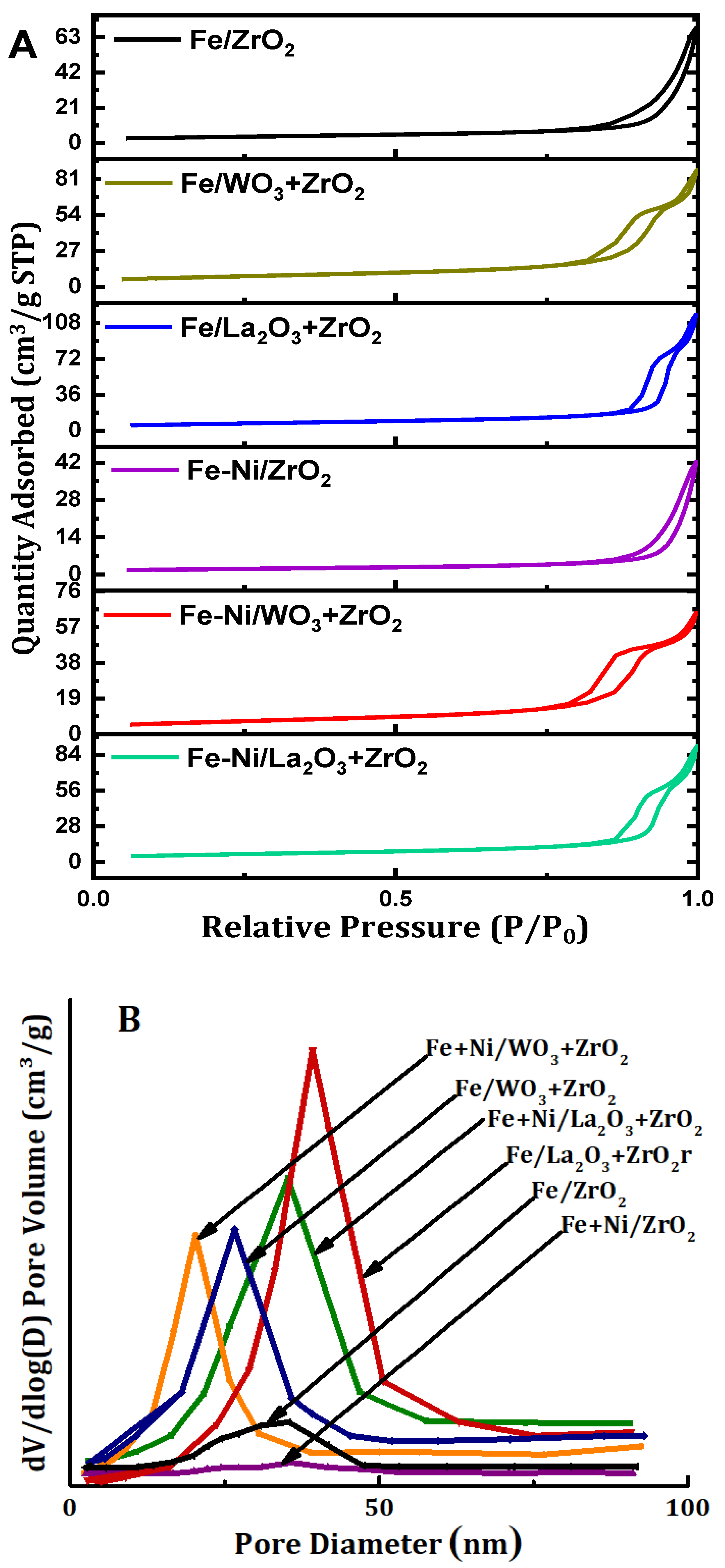
2.1.2. Textural Properties

The textural properties of the supports as well as those of the synthesized fresh catalyst samples were determined by the N2 adsorption-desorption. Table 1 contains the results of the different supports and the fresh catalyst samples, respectively. Furthermore, the isotherms are displayed in Figure 2A while Figure 2B contains the pore size distribution of the samples in question. Relating the surface areas of the supports to those of their respective synthesized catalyst samples, we observed a huge decrease in the surface areas. It can be said that the addition of metals to the supports culminated in blockage of the pores of the supports. Furthermore, the pore volume and pore diameter of fresh catalysts also decreased vis-à-vis those of their corresponding supports. The N2 adsorption-desorption isotherms of all the catalysts in Figure 2A fall under type IV classification. This is typical of mesoporous materials. In addition, hysteresis loops can be observed in all these samples. According to IUPAC classification, the hysteresis loops are H3 type [24]. From Figure 2B, the pore sizes of the fresh catalyst samples fall within 2–50 nm. According to the IUPAC classification, this size range falls under the category of mesoporous materials.

2.1.3. Temperature-Programmed Reduction (TPR)
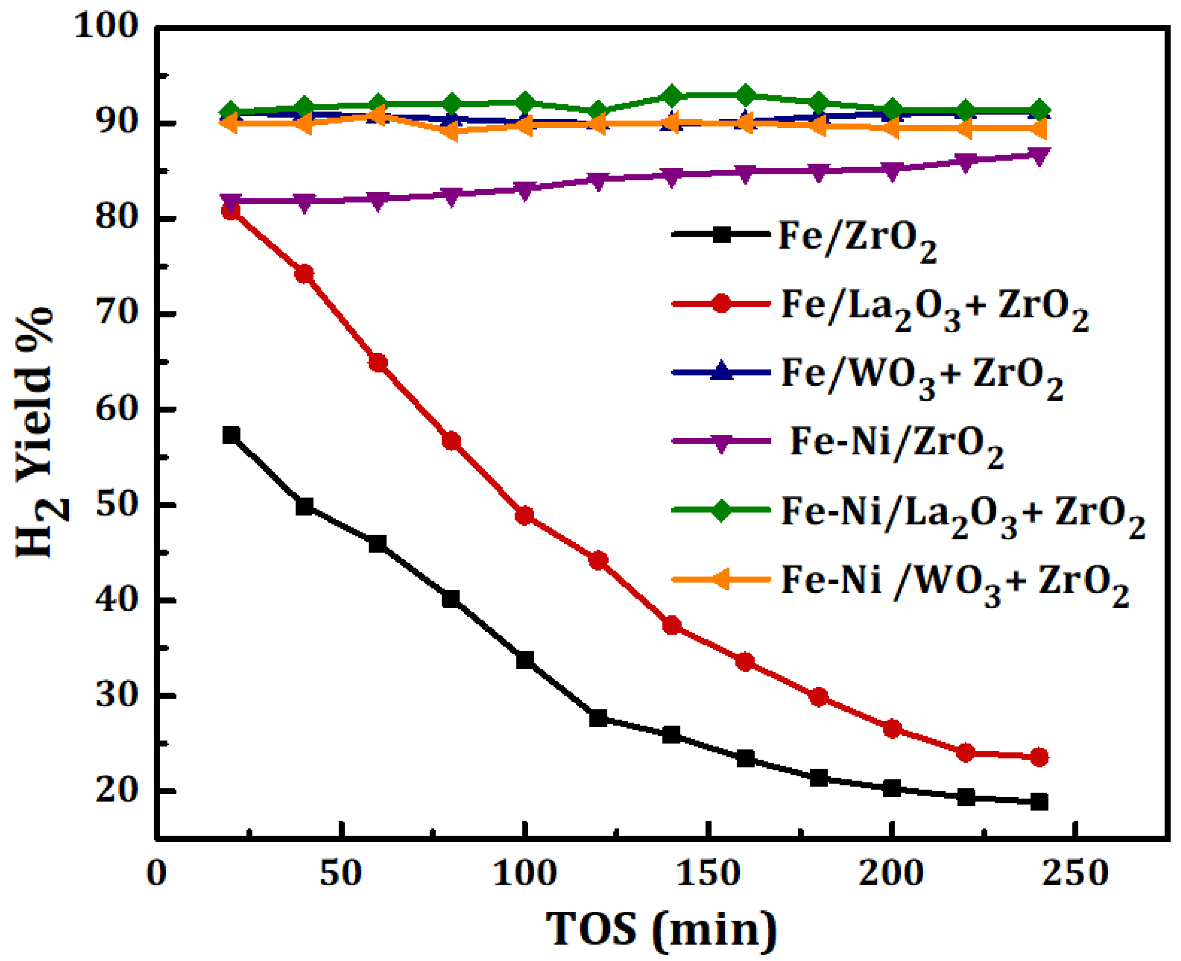
The reducibility, together with the degree of interaction between the metal and the different carriers, was studied using TPR for the Fe and Fe-Ni-supported fresh catalyst samples. As we have it in Figure 3, for Fe/x-ZrO2 (x = 0, La2O3 + ZrO2, WO3 + ZrO2), three reduction peaks at different temperatures can be seen in the TPR profile. The peaks represent the stepwise reduction of Fe3+ to Fe0, i.e., Fe2O3→Fe3O4→FeO→Fe. The peak appearing at the temperature range of 310–410 °C stands for the reduction of Fe2O3 to Fe3O4. Additionally, the peak within 430–700 °C can be attributed to the reduction from Fe3O4 to FeO. Lastly, the final stage of the reduction process to obtain zero-valence Fe can be assigned to the peak that appeared within 710–900 °C. Similar reduction behavior has been reported in different studies, such as the work done by Bayat et al. [15]. The reduction peak of Fe/WO3 + ZrO2 can be seen at a higher range in comparison with the other catalysts with only Fe. This could be as a result of the strong interaction that exists between Fe and its carrier (WO3 + ZrO2).
For the Fe-Ni impregnated on different carriers, the reduction profiles show almost the same trend as the single metal-supported samples (Fe/ZrO2, Fe/La2O3 + ZrO2, and Fe/WO3 + ZrO2) according to the H2-TPR analysis. However, it is obvious that the Fe-Ni-supported catalysts have higher hydrogen consumption, which translates to higher intensity peaks. This could be because of the presence of NiO. Furthermore, there is a slight shift in the reduction temperature of the bi-metallic catalysts with the third peak appearing at a lower reduction temperature. In addition, the reduction peaks of NiO appear to have coincided with that of the progressive reduction of Fe3O4. Usually NiO is used to undergo reduction at about 345, 460 and 700 °C on typical support [14,25,26].

2.2. Catalytic Test

The results of methane decomposition (MD) for the duration of 4 h over Fe and Fe-Ni catalysts supported on different carriers are shown in Figure 4. The feed’s space velocity was kept at 4000 mL(hgcat)−1 while the reaction was carried out at 1 atmosphere and 800 °C. The difference in the catalysts’ activities has been reported in terms of H2 yield. The results reveal the effect of adding La2O3, WO3 to ZrO2 and the role of Ni in the catalysts’ performances. According to Figure 4, Fe/WO3 + ZrO2 has the highest H2 yield of about 90% among the monometallic-supported samples. Fe/ZrO2 and Fe/La2O3 + ZrO2 had a high initial H2 yield corresponding to about 58% and 80%, respectively, but plummeted earlier during the time-on-stream. This could be as a result of carbon deposits, formed from MD, enveloping the active metal sites. In all, Fe supported on the ZrO2-doped carrier (i.e., WO3 + ZrO2 and La2O3 + ZrO2) gave a higher H2 yield than Fe supported on the pristine ZrO2. Additionally, Fe/WO3 + ZrO2, with the highest yield of H2, showed excellent stability during the test. The performance of Fe/WO3 + ZrO2 can be attributed to the properties of its support: like the unique acidity of WO3, its chemical and thermal stability [18,19,20]. The addition of WO3 to the pristine ZrO2 enhanced the diffusion of carbon deposits from the MD, making the active metal sites accessible to the feed, and its reported thermal stability contributes to the inhibition of metal aggregation, sintering, and the loss of catalyst structure.
For the Fe-Ni-supported catalysts, the addition of Ni had a positive impact on the stability as well as the yield of H2 for both Fe/ZrO2 and Fe/La2O3 + ZrO2 catalysts. The initial H2 yield can be seen to have increased from 58% to 82% for Fe/ZrO2 and from 80% to 90% for Fe/La2O3 + ZrO2. The influence of Ni was not really pronounced in the activity of the Fe-Ni/WO3 + ZrO2 catalyst, however, it raised the percentage yield of H2 to a value above 90% and maintained the stability. Similarly, it was reported by Anis et al. that the Ni addition to Fe/Al2O3 enhanced the performance of the catalyst in terms of methane conversion and hydrogen yield [27]. Ni being an active metal with stronger reduction potential than Fe in the electrochemical series would do more in reaction than Fe. The influence of the Ni addition in catalytic methane decomposition in the past works is summarized in Table 2.
Furthermore, activities of the catalysts can be related to the individual specific surface area. High surface area could translate to more room for active metal dispersion, which would transform the feed to the product after adsorption. It has been reported that a higher specific surface area and pore volume do enhance catalyst performance [28]. In this study, Fe/ZrO2 had the lowest specific surface area (12.74 m2/g) and performed the worst while Fe/WO3 + ZrO2 had the highest area (26.68 m2/g) and gave the best performance.
We compared the H2 yield from past research works with this study. The results obtained, together with the operating conditions, are summarized in Table 2. In addition to that, the carbon yields that resulted from the methane decomposition reactions in this study as well as that of the past work are shown in Table 3 for comparison.
Fakeeha et al. [25], studied hydrogen and carbon yield in methane decomposition over Fe supported on MgO and TiO2. In their research, magnesia-supported Fe gave better activity at high Fe loading of about 30–40%. This shines a light on the adoption of higher Fe content in catalytic methane decomposition, as this will assist in the diffusion of carbon deposits and ultimately bring about better stability for the catalyst. For better understanding of the catalysts’ performances, their CH4 conversions are shown in the Figure 5 alongside their H2 yields.

2.3. Characterization of Spent Catalysts and Carbon Produced

2.3.1. Thermo-Gravimetric Analysis (TGA)

Thermo-gravimetric (TG) analysis was carried out on the used catalyst samples. They were taken out of the reactor and kept in a safe container. The results of the TG analysis are presented in Figure 6. This figure shows the percentage of weight loss as a function of temperature. The weight loss is a representation of the amount of carbon deposits over the used catalysts that have been converted to CO/CO2 while being heated in the atmosphere. Fe/WO3 + ZrO2 had the highest amount of carbon deposits of about 58% while the least reactive Fe/ZrO2 had the lowest carbon deposits amounting to about 11%.
For the used Fe-Ni-supported catalysts, the same trend as in Fe/x-ZrO2 (x = 0, La2O3, WO3) was observed with a difference of higher carbon deposits for both Fe-Ni/ZrO2 and Fe-Ni/La2O3 + ZrO2. The increase in carbon deposits can be linked to the presence of Ni, which enhanced the performance of the catalysts as shown before in Figure 4.

2.3.2. Raman Spectroscopy Analysis

Further post-reaction analysis was performed on the used catalysts to determine the degree of graphitization of the carbon deposits. The spectra obtained from the Raman analysis are displayed in Figure 7. For all the used catalysts, peaks related to the D (Defect) and G (Graphite) bands can be seen at approximately 1472 and 1535 cm−1 Raman shifts, respectively. The G band represents the ideal vibration mode of the well-ordered graphitic layers having E2g symmetry, while the D band is caused by defects in the graphitic lattice. Its source has been expatiated by the double resonant Raman scattering [36].
It has been reported that the ratio of the integral intensities of ID to IG and the bands’ full width at half maximum height (FWHM) could be correlated with the microstructure of carbonaceous materials. Additionally, the intensity ratio, ID/IG, represents the degree of the crystalline order of the graphite in the carbon deposits [37,38]. The implication of this is that a higher intensity, above 1, indicates a higher structural disorder in the carbon deposits, while a lower ratio, below 1, represents lesser structural disorder [38]. From Figure 7, Fe/WO3 + ZrO2 gave carbon deposits with the highest structural defect, while Fe-Ni/La2O3 + ZrO2 had the least structurally disordered carbon deposits. This implies that the carbon deposits generated by the Fe/WO3 + ZrO2 catalyst are mostly amorphous and those of the Fe-Ni/La2O3 + ZrO2 catalyst contain higher amounts of graphite. It can be seen that the ID/IG ratios of the bimetallic catalysts are less than those of the monometallic counterparts, with the exception of Fe/ZrO2. Hence, the addition of Ni improved the structural order of the carbon deposits on Fe/WO3 + ZrO2 and Fe-Ni/La2O3 + ZrO2.

3. Materials and Methods

3.1. Materials

Iron nitrate nonahydrate [Fe(NO3)3·9H2O; 99%] and nickel nitrate hexahydrate [Ni(NO3)2·6H2O; 99%] were obtained from Sigma-Aldrich, (Steinheim, Germany). Zirconium hydroxide (Zr(OH)2, lanthanum- and zirconia-mixed oxides [9%La2O3-ZrO2], and tungsten oxide zirconia mixture [10%WO3-ZrO2] were obtained from Daiichi Kigenso (Osaka, Japan). All chemicals were used as-received without further purification.

3.2. Catalyst Preparation

The supported Fe monometallic catalyst and Fe-Ni bi-metallic catalysts were synthesized by an incipient wetness-impregnation technique. Briefly, a stoichiometric amount of the investigated supports was added to an aqueous solution containing an appropriate amount of iron precursor or a mixture of iron and nickel precursors. Fe and Fe-Ni contents were maintained at 20 wt%, i.e., for the monometallic samples, Fe loading was 20% while both Fe and Ni had 20% loading each for the bimetallic samples. The mixture was stirred for 4 h before drying at 120 °C overnight. After that, the resultant samples were calcined in the air by heating from the ambient temperature to 800 °C over a 7-h period and keeping it at this temperature for 3 h. The resulting calcined samples are designated as Fe/x-ZrO2 and Fe-Ni/x-ZrO2, where (x = 0, La2O3, ZrO2).

3.3. Catalyst Activity

Methane decomposition reaction on the surface of Fe and Fe-Ni-supported catalysts was carried out in the PID Eng & Tech microactivity reaction system. The experiments were performed by using 300 mg of the prepared catalysts sandwiched between two layers of glass wool in the fixed bed reactor. Before starting the reaction, the synthesized catalyst was activated in situ at 800 °C in a hydrogen atmosphere for 1.5 h. The reactants’ gas mixture, consisting of 65% CH4 with N2 as a balance, was introduced into the reactor at a total flow rate of 20 mL/min. The decomposition of the CH4 reaction was conducted at atmospheric pressure and 800 °C reaction temperature. The analysis was started 20 min after the beginning of the decomposition reaction and contained for 240 min for each of the synthesized catalysts. The decomposition products, as well as the unconverted reactants, were analyzed by an online Shimadzu GC 2004 gas chromatography.
The yield of H2 was calculated based on the following equation:
H 2 Yield :   Y H 2 = moles   of   H 2   produced 2 × moles   of   CH 4   in   the   feed × 100 %

3.4. Catalyst Characterization

Powder X-ray diffraction (XRD) patterns of prepared monometallic (Fe) as well as the bimetallic (Fe-Ni) catalysts were conducted using the Miniflex Rigaku diffractometer operated at 40 kV and 40 mA, equipped with Cu Kα X-ray radiation. The isotherms of nitrogen sorption were determined in the Micromeritics Tristar II 3020 surface area and porosity analyzer at −196 °C after the samples were outgassed at 200 °C for 3 h to remove any adsorbed gases or vapors. The distributions of pore size of the samples were analyzed from the adsorption profiles of isotherms using the Barrett–Joyner–Halenda (BJH) model. The H2-TPR of the synthesized fresh catalysts as well as the spent samples was performed on the Micromeritics Auto Chem II 2920. The analyses were conducted over a temperature range of 50–800 °C and in a mixture of 40 mL/min flow of 10% H2/Ar in the TPR analysis. The coke formation and the amount of carbon deposit on the surface of tested catalysts were measured by the thermo-gravimetric analyzer (Shimadzu-TGA). The samples were heated up to 1000 °C while the temperature was ramped at 10 °C/min. The deposited carbons were burned in an air atmosphere by heating the samples up to 1000 °C at a rate of 10 °C/min and the weight losses were recorded. A laser Raman spectroscopy NMR—4500 was used to study the extent of graphitization of the carbon deposited over the used catalysts. The measurement was performed using a 5x magnification objective lens and beam excitation wavelength of 532 nm. The adopted range for spectra recording was 1350–1600 cm−1.

4. Conclusions

This research focused on hydrogen yield from catalytic methane decomposition using Fe and Fe-Ni supported on different carriers. The catalysts were synthesized by the wet-impregnation method and tested in the reaction under atmospheric conditions, at 800 °C, and at 4000 mL/(hgcat)−1 space velocity.
Among the monometallic catalysts, Fe/WO3 + ZrO2 had the highest H2 yield of about 90%. Its excellent performance was attributed to the special properties of its support such as dense acid sites, the ability to form Bronsted acid on reduction, stable chemical and thermal properties, and its wide use in the cracking of heavy crude oil fractions. When Ni was added to Fe/x-ZrO2 (x = 0, La2O3, WO3), a significant increase in the activities of Fe/ZrO2 and Fe/La2O3 + ZrO2 was observed. These two catalysts had a relatively low conversion and poor stability before the addition of Ni.
Both fresh and used catalysts were analyzed by some characterization techniques. The X-ray diffractogram of the fresh catalyst samples showed the existing phases. Monoclinic and tetragonal zirconia were identified on all the samples at their typical angle of diffraction. The presence of La2O3 resulted into peaks with higher intensity. Crystal phases of iron oxide such as hematite and maghemite were found on all samples. However, magnetite was identified only on the bi-metallic samples. Additionally, NiO phases were seen on the Ni-promoted samples. The nitrogen physisorption analysis revealed that the surface areas of the catalysts decreased relative to their corresponding supports. This could be as a result of the active metals blocking the pores of the support. The TPR revealed the progression in the reduction of Fe to its zero-valent form and no interaction of iron oxide with the support was observed. The reduction profiles were virtually the same for Fe and Fe-Ni catalysts except that the intensity of the peaks was higher for the latter. Reduction peaks of NiO appeared to have coincided with those of Fe3O4, as reported reduction temperatures of NiO fall within range of those of iron oxide. Fe and Fe-Ni supported on WO3 + ZrO2 have the highest amount of carbon deposits compared to their counterparts according to the TG analysis. The Raman analysis revealed that the carbon deposited on the used catalysts has a higher structural defect, however, the structural disorder reduced with the addition of NiO.

Author Contributions

F.A.-M., S.K., and A.S.A.-F., writing—original draft preparation; S.K., A.S.A.-F., preparation of catalysts. F.A.-M., A.A.I., A.S.A.-A., and A.H.F. contributed to the analysis of the data and proofread the manuscript. All authors have read and agreed to the published version of the manuscript.

Funding

This research was funded by Deanship of Scientific Research, King Saud University, grant number RGP-119.

Acknowledgments

The authors would like to express their sincere appreciation to the Deanship of Scientific Research at King Saud University for funding this research project (RGP-119). Additionally, to KIGAKU DAIICHI KOGYO CO.; LTD Osaka, for the gift of valuable support used in the synthesis of catalysts.

Conflicts of Interest

The authors declare no conflicts of interest.

References

  1. Heiserman, D.L. Exploring Chemical Elements and Their Compounds; Tab Books: New York, NY, USA, 1992; ISBN 9780830630158. [Google Scholar]
  2. Suess, H.E.; Urey, H.C. Abundances of the elements. Rev. Mod. Phys. 1956, 28, 53–74. [Google Scholar] [CrossRef]
  3. Seeds, M.A. Horizons: Exploring the Universe; Brooks Cole: Pacific Grove, CA, USA, 2016; ISBN 1305957377. [Google Scholar]
  4. Hetland, J.; Mulder, G. In search of a sustainable hydrogen economy: How a large-scale transition to hydrogen may affect the primary energy demand and greenhouse gas emissions. Int. J. Hydrog. Energy 2007, 32, 736–747. [Google Scholar] [CrossRef]
  5. Kang, D.; Lee, J.W. Enhanced methane decomposition over nickel–carbon–B2O3 core–shell catalysts derived from carbon dioxide. Appl. Catal. B Environ. 2016, 186, 41–55. [Google Scholar] [CrossRef]
  6. Zhou, L.; Guo, Y.; Hideo, K. Unsupported nickel catalysts for methane catalytic decomposition into pure hydrogen. AIChE J. 2014, 60, 2907–2917. [Google Scholar] [CrossRef]
  7. Nakagawa, K.; Nishitanigamo, M.; Ando, T. Hydrogen production from methane for fuel cell using oxidized diamond-supported catalysts. Int. J. Hydrog. Energy 2005, 30, 201–207. [Google Scholar] [CrossRef]
  8. Rodriguez, N. A review of catalytically grown carbon nanofibers. J. Mater. Res. 1993, 8, 3233–3250. [Google Scholar] [CrossRef]
  9. Li, Y.; Zhang, B.; Xie, X.; Liu, J.; Xu, Y.; Shen, W. Novel Ni catalysts for methane decomposition to hydrogen and carbon nanofibers. J. Catal. 2006, 238, 412–424. [Google Scholar] [CrossRef]
  10. Abbas, H.F.; Daud, W.W. Thermocatalytic decomposition of methane for hydrogen production using activated carbon catalyst: Regeneration and characterization studies. Int. J. Hydrog. Energy 2009, 34, 8034–8045. [Google Scholar] [CrossRef]
  11. Li, J.; Smith, K.J. Methane decomposition and catalyst regeneration in a cyclic mode over supported Co and Ni catalysts. Appl. Catal. A Gen. 2008, 349, 116–124. [Google Scholar] [CrossRef]
  12. Ashik, U.; Abbas, H.F.; Abnisa, F.; Kudo, S.; Hayashi, J.-I.; Daud, W.M.A.W. Methane decomposition with a minimal catalyst: An optimization study with response surface methodology over Ni/SiO2 nanocatalyst. Int. J. Hydrog. Energy 2020, 45, 14383–14395. [Google Scholar] [CrossRef]
  13. Takenaka, S.; Shigeta, Y.; Tanabe, E.; Otsuka, K. Methane decomposition into hydrogen and carbon nanofibers over supported Pd−Ni catalysts: Characterization of the catalysts during the reaction. J. Phys. Chem. B 2004, 108, 7656–7664. [Google Scholar] [CrossRef]
  14. Bayat, N.; Rezaei, M.; Meshkani, F. Hydrogen and carbon nanofibers synthesis by methane decomposition over Ni–Pd/Al2O3 catalyst. Int. J. Hydrog. Energy 2016, 41, 5494–5503. [Google Scholar] [CrossRef]
  15. Escobar, C.; Perez-Lopez, O.W. Hydrogen production by methane decomposition over Cu–Co–Al mixed oxides activated under reaction conditions. Catal. Lett. 2014, 144, 796–804. [Google Scholar] [CrossRef]
  16. Bayat, N.; Rezaei, M.; Meshkani, F. Methane decomposition over Ni–Fe/Al2O3 catalysts for production of COx-free hydrogen and carbon nanofiber. Int. J. Hydrog. Energy 2016, 41, 1574–1584. [Google Scholar] [CrossRef]
  17. Torres, D.; Pinilla, J.; Suelves, I. Co-, Cu- and Fe-doped Ni/Al2O3 catalysts for the catalytic decomposition of methane into hydrogen and carbon nanofibers. Catalysts 2018, 8, 300. [Google Scholar] [CrossRef] [Green Version]
  18. Kabe, T.; Qian, W.; Funato, A.; Okoshi, Y.; Ishihara, A. Hydrodesulfurization and hydrogenation on alumina-supported tungsten and nickel-promoted tungsten catalysts. Phys. Chem. Chem. Phys. 1999, 1, 921–927. [Google Scholar] [CrossRef]
  19. Rezgui, Y.; Guemini, M. Effect of acidity and metal content on the activity and product selectivity for n-decane hydroisomerization and hydrocracking over nickel–tungsten supported on silica–alumina catalysts. Appl. Catal. A Gen. 2005, 282, 45–53. [Google Scholar] [CrossRef]
  20. Baertsch, C.D.; Komala, K.T.; Chua, Y.-H.; Iglesia, E. Genesis of brønsted acid sites during dehydration of 2-butanol on tungsten oxide catalysts. J. Catal. 2002, 205, 44–57. [Google Scholar] [CrossRef] [Green Version]
  21. Pudukudy, M.; Yaakob, Z.; Shan, S.; Takriff, M.S. Catalytic decomposition of methane over rare earth metal (Ce and La) oxides supported iron catalysts. Appl. Surf. Sci. 2019, 467–468, 236–248. [Google Scholar] [CrossRef]
  22. Al-Fatesh, A.S.; Kasim, S.O.; Ibrahim, A.A.; Al-Awadi, A.S.; Abasaeed, A.E.; Fakeeha, A.H.; Awadallah, A.E. Catalytic methane decomposition over ZrO2 supported iron catalysts: Effect of WO3 and La2O3 addition on catalytic activity and stability. Renew. Energy 2020, 155, 969–978. [Google Scholar] [CrossRef]
  23. Titus, J.; Roussière, T.; Wasserschaff, G.; Schunk, S.; Milanov, A.; Schwab, E.; Wagner, G.; Oeckler, O.; Gläser, R. Dry reforming of methane with carbon dioxide over NiO–MgO–ZrO2. Catal. Today 2016, 270, 68–75. [Google Scholar] [CrossRef]
  24. Sing, K.S.W.; Everett, D.H.; Haul, R.A.W.; Moscou, L.; Pierotti, R.A.; Rouquerol, J.; Siemieniewska, T. Reporting physisorption data for gas/solid systems. In Handbook of Heterogeneous Catalysis; Wiley: Hoboken, NJ, USA, 2008; pp. 1217–1230. [Google Scholar]
  25. Fakeeha, A.; Ibrahim, A.A.; Aljuraywi, H.; Alqahtani, Y.; Alkhodair, A.; Alswaidan, S.; Abasaeed, A.E.; Kasim, S.O.; Mahmud, S.; Al-Fatesh, A.S. Hydrogen production by partial oxidation reforming of methane over Ni catalysts supported on high and low surface area alumina and zirconia. Processes 2020, 8, 499. [Google Scholar] [CrossRef]
  26. Zhang, M.; Zhang, J.; Zhang, X.; Zhou, Z.; Song, F.; Zhang, Q.; Tan, Y.; Han, Y. How the reflux treatment stabilizes the metastable structure of ZrO2 and improves the performance of Ni/ZrO2 catalyst for dry reforming of methane? Energy Convers. Manag. 2020, 216, 112950. [Google Scholar] [CrossRef]
  27. Zhang, J.; Xie, W.; Li, X.; Hao, Q.-Q.; Chen, H.; Ma, X. Methane decomposition over Ni/carbon catalysts prepared by selective gasification of coal char. Energy Convers. Manag. 2018, 177, 330–338. [Google Scholar] [CrossRef]
  28. Ashok, J.; Subrahmanyam, M.; Venugopal, A. Hydrotalcite structure derived Ni–Cu–Al catalysts for the production of H2 by CH4 decomposition. Int. J. Hydrog. Energy 2008, 33, 2704–2713. [Google Scholar] [CrossRef]
  29. Fakeeha, A.H.; Ibrahim, A.A.; Naeem, M.A.; Khan, W.U.; Abasaeed, A.E.; Alotaibi, R.L.; Al-Fatesh, A.S. Methane decomposition over Fe supported catalysts for hydrogen and nano carbon yield. Catal. Sustain. Energy 2015, 2, 71–82. [Google Scholar] [CrossRef] [Green Version]
  30. Fakeeha, A.H.; Ibrahim, A.A.; Khan, W.U.; Seshan, K.; Al Otaibi, R.L.; Al-Fatesh, A.S. Hydrogen production via catalytic methane decomposition over alumina supported iron catalyst. Arab. J. Chem. 2018, 11, 405–414. [Google Scholar] [CrossRef] [Green Version]
  31. Al-Fatesh, A.; Fakeeha, A.; Ibrahim, A.; Khan, W.; Atia, H.; Eckelt, R.; Seshan, K.; Chowdhury, B. Decomposition of methane over alumina supported Fe and Ni–Fe bimetallic catalyst: Effect of preparation procedure and calcination temperature. J. Saudi Chem. Soc. 2018, 22, 239–247. [Google Scholar] [CrossRef] [Green Version]
  32. Fakeeha, A.H.; Al-Fatesh, A.S.; Chowdhury, B.; Ibrahim, A.; Khan, W.U.; Hassan, S.; Sasudeen, K.; Abasaeed, A.E. Bi-metallic catalysts of mesoporous Al2O3 supported on Fe, Ni and Mn for methane decomposition: Effect of activation temperature. Chin. J. Chem. Eng. 2018, 26, 1904–1911. [Google Scholar] [CrossRef]
  33. Chesnokov, V.V.; Chichkan, A.S. Production of hydrogen by methane catalytic decomposition over Ni–Cu–Fe/Al2O3 catalyst. Int. J. Hydrog. Energy 2009, 34, 2979–2985. [Google Scholar] [CrossRef]
  34. Reshetenko, T.; Avdeeva, L.; Ushakov, V.; Moroz, E.; Shmakov, A.; Kriventsov, V.; Kochubey, D.; Pavlyukhin, Y.; Chuvilin, A.; Ismagilov, Z. Coprecipitated iron-containing catalysts (Fe-Al2O3, Fe-Co-Al2O3, Fe-Ni-Al2O3) for methane decomposition at moderate temperatures. Appl. Catal. A Gen. 2004, 270, 87–99. [Google Scholar] [CrossRef]
  35. Chen, J.; Ma, Q.; Rufford, T.E.; Li, Y.; Zhu, Z. Influence of calcination temperatures of Feitknecht compound precursor on the structure of Ni–Al2O3 catalyst and the corresponding catalytic activity in methane decomposition to hydrogen and carbon nanofibers. Appl. Catal. A Gen. 2009, 362, 1–7. [Google Scholar] [CrossRef]
  36. Dresselhaus, M.S.; Jorio, A.; Hofmann, M.; Dresselhaus, G.; Saito, R. Perspectives on carbon nanotubes and graphene Raman spectroscopy. Nano Lett. 2010, 10, 751–758. [Google Scholar] [CrossRef] [PubMed]
  37. Kameya, Y.; Hanamura, K. Kinetic and Raman spectroscopic study on catalytic characteristics of carbon blacks in methane decomposition. Chem. Eng. J. 2011, 173, 627–635. [Google Scholar] [CrossRef]
  38. Ivleva, N.P.; Messerer, A.; Yang, X.; Niessner, R.; Pöschl, U. Raman microspectroscopic analysis of changes in the chemical structure and reactivity of soot in a diesel exhaust aftertreatment model system. Environ. Sci. Technol. 2007, 41, 3702–3707. [Google Scholar] [CrossRef] [PubMed]
Figure 1. XRD profiles for the Fe/x-ZrO2- and Fe-Ni/x-ZrO2-supported (x = 0, La2O3, WO3) catalysts.
Catalysts 10 00793 g001
Figure 2. (A) The N2 physisorption isotherms and (B) pore size distribution of Fe and Fe-Ni-supported x-ZrO2 (x = 0, La2O3, WO3).
Catalysts 10 00793 g002
Figure 3. Temperature-programmed reduction (TPR) profiles of the Fe and Fe-Ni catalysts supported on different carriers.
Catalysts 10 00793 g003
Figure 4. H2 yield for Fe, Fe-Ni/x-ZrO2 (x = 0, La2O3, WO3) catalysts studied at 1 atm, 800 °C, and 4000 mL(hgcat)−1.
Catalysts 10 00793 g004
Figure 5. CH4 conversion of Fe [22], Fe-Ni/x-ZrO2 (x = 0, La2O3, WO3) at the operating conditions of 1 atm, 800 °C, and 4000 mL(hgcat)−1.
Catalysts 10 00793 g005
Figure 6. The thermo-gravimetric (TG) analysis results for Fe and Fe-Ni supported on x-ZrO2 (x = 0, La2O3, WO3).
Catalysts 10 00793 g006
Figure 7. Raman analysis of spent supported Fe and Fe-Ni catalysts.
Catalysts 10 00793 g007
Table 1. N2 adsorption-desorption results of the supports and synthesized samples.
Fresh SamplesZrO2WO3 + ZrO2La2O3 + ZrO2Fe/ZrO2Fe/WO3 + ZrO2Fe/La2O3 + ZrO2Fe-Ni/ZrO2Fe-Ni/WO3 + ZrO2Fe-Ni/La2O3 + ZrO2
BET surface area (m2/g)58.797.762.812.726.724.37.223.421.1
Av. Pore diameter (nm)68.915.321.335.421.631.743.618.227.4
Pore volume (cm3/g)0.30.30.30.10.10.20.10.00.1
Table 2. Comparison of H2 yield of past related work with the present study.
CatalystH2 Yield (%)Mass of Catalyst (g)Space Velocity (mLgcat−1 h−1)Reaction Temperature (°C)Reference
30%Fe/MgO450.35000700[29]
Fe/CeO26624500800[21]
Fe/La2O35024500800[21]
20%Fe/Al2O3800.35000800[30]
5%Ni-20%Fe/Al2O3650.35000700[31]
15%Ni–30%/Fe/Al2O3770.35000700[32]
70%Ni–10%Cu–10%Fe/Al2O3771.52867700[33]
20%Fe/WO3 + ZrO2900.34000800Present work
Table 3. Comparison of carbon yield of past related work with the present study.
CatalystCarbon Yield (g C/gcat)Space Velocity (mLg−1 h−1)Reaction Temperature (°C)Reference
30%Fe/MgO5.55000700[29]
70%Ni–10%Cu–10%Fe/Al2O382867700[33]
50Fe-6Co-Al2O341.045,000675[34]
62Fe-8Ni-Al2O3122.045,000675[34]
NiO–Al2O388900,000500[35]
20%Fe/WO3 + ZrO20.584000800Present work

