Article

Synergistic Effect of Dielectric Barrier Discharge Plasma and TiO2-Pillared Montmorillonite on the Degradation of Rhodamine B in an Aqueous Solution

by
Mikhail F. Butman
1,
Andrey A. Gushchin
1,
Nikolay L. Ovchinnikov
1,
Grigoriy I. Gusev
1,
Nikolay V. Zinenko
1,
Sofia P. Karamysheva
2 and
Karl W. Krämer
3,*
1
Ivanovo State University of Chemistry and Technology, 153000 Ivanovo, Russia
2
Industrial Laboratory, SCAMT Institute, ITMO University, 191002 Saint Petersburg, Russia
3
Department of Chemistry and Biochemistry, University of Bern, 3012 Bern, Switzerland
*
Author to whom correspondence should be addressed.
Catalysts 2020, 10(4), 359; https://doi.org/10.3390/catal10040359
Submission received: 3 March 2020 / Revised: 20 March 2020 / Accepted: 22 March 2020 / Published: 25 March 2020
(This article belongs to the Special Issue Recent Advances in TiO2 Photocatalysts)

Abstract

:
Photocatalytic, plasma and combined plasma–photocatalytic processes were applied for the destruction of a model pollutant, Rhodamine B dye, in an aqueous solution (concentration of 40 mg/L). For this purpose TiO2-pillared montmorillonite was used as a photocatalyst (characterized by X-ray analysis and low-temperature nitrogen adsorption/desorption). It was prepared by the method of intercalation of titanium hydroxocomplexes, including hydrothermal activation of the process and preliminary mechanical treatment of the layered substrate. The dielectric barrier discharge (DBD) plasma in the presence of photocatalysts increases the efficiency of dye degradation (100%, 8 s) compared to plasmolysis (94%) and UV photolysis (92%, 100 min of UV irradiation); in contrast to photolysis, destructive processes are more profound and lead to the formation of simple organic compounds such as carboxylic acids. The plasma–catalytic method enhances by 20% the energetic efficiency of the destruction of Rhodamine B compared to DBD plasma. The efficiency of dye destruction with the plasma–catalytic method increases with the improvement of the textural properties of the photocatalyst.

Graphical Abstract

1. Introduction

Purification of natural water resources from organic dyes due to their resistance to decomposition processes [1] is a problem of topical interest [2,3,4,5]. Conventional treatment technologies such as biological, physical and chemical methods [6,7,8,9,10] are neither cheap nor provide the required efficiency. Recently, special attention has been paid to advanced oxidative process (AOP) technologies, the use of which allows for the decomposition of pollutants into less toxic products with the processes of destruction occurring at high rates, which is a significant advantage [11,12,13].
One of the possible ways to intensify wastewater treatment processes is the dielectric barrier discharge (DBD), which has already found wide application in environmental protection systems [14,15,16]. High purification efficiency can be achieved by combining plasma-chemical and photocatalytic purification methods with the observation of a synergistic effect [17,18,19] while reducing energy costs [20]. In this case, radiation quanta enhance the oxidation processes due to the formation of additional active particles, such as, for example, those in the TiO2 photocatalyst–plasma system [21,22]:
TiO 2 + h υ e + h +
h + + H 2 O H + + O H *
h + + O H O H *
OH * + OH * H 2 O 2
O 2 + e O 2 *
2 O 2 * + 2 H 2 O H 2 O 2 + 2 O H + O 2
O 3 + O H * O 2 + H O 2 *
O 3 + H * O 2 + O H *
where e + h+ are the electron-hole pairs formed on the surface of the catalyst. Moreover, a synergistic effect may arise due to the promotion of the photocatalyst, which consists in assumed inhibition of the recombination of e + h+ pairs on the surface of TiO2 and continuous photocatalyst regeneration under DBD [23].
The presence of an intense UV component of the DBD plasma [24] simplifies the approaches to the selection of effective photocatalysts. In particular, for the most common TiO2 photocatalysts, in this case, it is not urgent to reduce the width of the forbidden zone by doping to shift the working radiation range to the visible region, which is essential when using only the photocatalytic purification method. Therefore, the best choice for the plasma–catalytic purification method is applying the advanced catalytic systems based on titanium oxide [25,26], in particular, its nanoscale forms [27].
However, the use of nanoparticles of pure TiO2 is hindered by some limitations such as low adsorption capacity and the possibility of particle agglomeration, which reduce its photocatalytic efficiency for the processes of purifying water from pollutants of organic origin. To overcome these limitations, titanium dioxide nanoparticles are distributed on mineral carriers such as natural clay minerals [28], particularly montmorillonite (MM) [29]. The TiO2-pillared montmorillonite possesses a highly developed specific surface area and exhibits high activity in various photocatalytic processes, including photolysis of organic dyes [30]. Recently we proposed and successfully applied a new approach to the synthesis of TiO2-pillared montmorillonite with a high degree of crystallinity for the TiO2 pillars (nanocrystals) representing a mixture of the anatase and rutile phases, and with improved adsorption and photocatalytic activities as a result of hydrothermally activated intercalation of titanium polyhydroxocomplexes [31]. Moreover, when obtaining TiO2-pillared MM, along with hydrothermal activation of the intercalation of titanium polyhydroxocomplexes we have used preliminary mechanical treatment of the original substrate [32]. This allowed for a significant improvement of the textural characteristics, in particular, a specific surface area and porosity of pillared materials due to a decrease in the size of MM particles during mechanical processing, and, therefore, an increase in the area of the interphase boundary through which ion exchange occurs.
Among the various dyes used in various fields of business activity, Rhodamine B has found wide application in the textile and food industries [33], in laser technology [34], and also used as a biomarker and molecular probe [35,36], electrochemical luminescent sensitizer [37], and also it is a sensitizer in combination with metal oxides in solar panels [38]. Rhodamine B refers to toxic compounds that have an irritating effect on the mucous membranes and skin. This dye has carcinogenic properties, exhibits neurotoxic effects and has a chronic toxic effect on aquatic organisms and humans [39]. Thus, the purification of water bodies from Rhodamine B is an urgent task to protect the environment and human health.
This paper presents the results of studying the destruction of Rhodamine B in a combined plasma–photocatalytic process using TiO2-pillared montmorillonite as a photocatalyst. The effects of various factors, such as discharge characteristics (current power and frequency), processing time and textural properties of the photocatalyst, on the purification process are assessed.

2. Results and Discussion

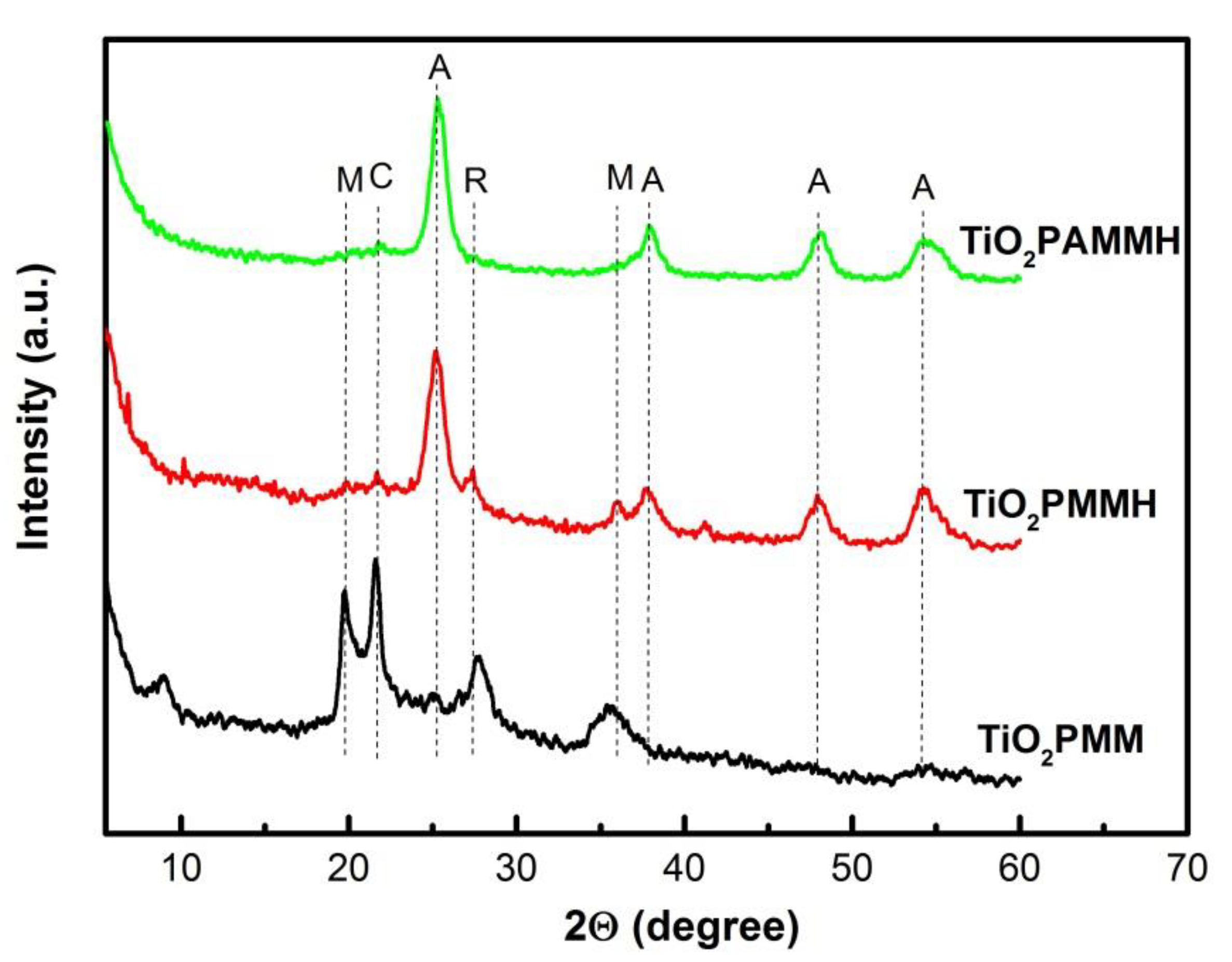
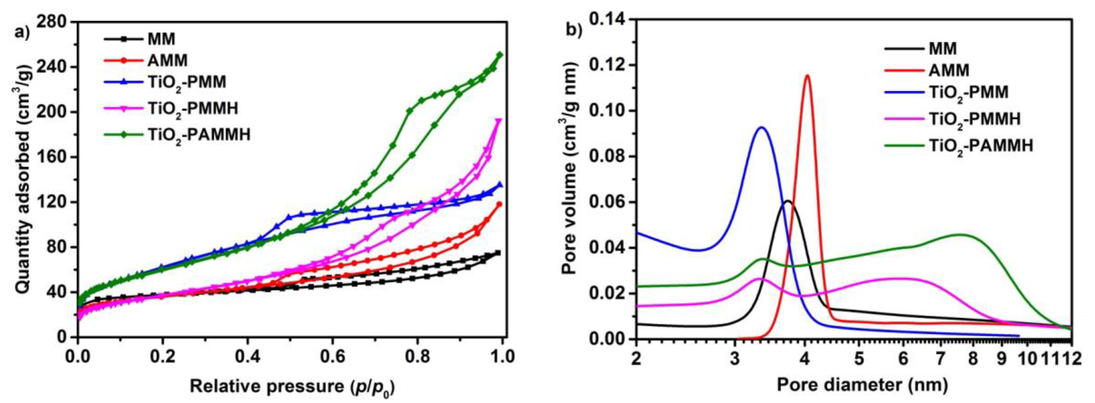
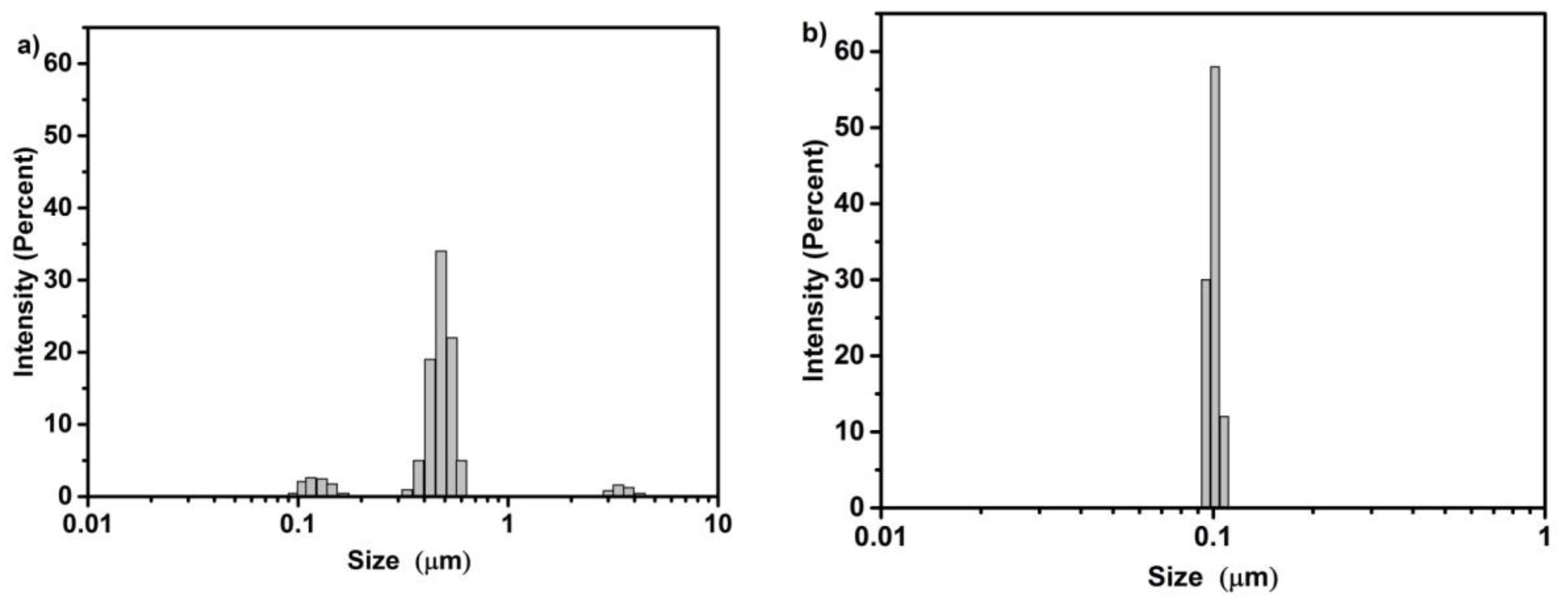
2.1. X-ray Diffraction, Textural Characterization and Particle Size Distribution

The characterization of the photocatalysts is discussed in the following. The photocatalysts were prepared as detailed below in Section 3.2.1. Throughout the text the following nomenclature for the samples was used: montmorillonite—MM; activated montmorillonite—AMM; TiO2-pillared montmorillonite—TiO2-PMM (method I); TiO2-pillared hydrothermally treated montmorillonite—TiO2-PMMH (method II) and TiO2-pillared hydrothermally treated and activated montmorillonite—TiO2-PAMMH (method III).
The original matrices and pillared materials were characterized by X-ray diffraction (XRD), see Figure 1. X-ray analysis was performed using an X-ray diffractometer Bruker D8 Advance (Bruker AXS GmbH, Karlsruhe, Germany). The average crystallite size of the TiO2 photoactive phase, anatase, was evaluated using the Scherrer’s method [40].
The pillared samples were characterized by peaks corresponding to the montmorillonite (2θ = 19.8° and 35.6°) and cristobalite (2θ = 21.7°) phases. The latter was a secondary product, which was formed in synthetic conditions with a low pH value of the medium. The diffractogram of the TiO2-PMM samples shows broad and weak peaks of both anatase (at 2θ = 25.3°, 47.8° and 54.4°) and rutile (at 2θ = 27.7°), whereas in the case of the TiO2-PMMH and TiO2-PAMMH samples these peaks were significantly sharper and more intense; moreover the anatase peak at 2θ = 37.7° became visible as well. These results demonstrated that in the preparations of photocatalysts by the methods II and III the TiO2 pillars crystallized in the anatase and rutile phases much more readily; the TiO2 crystallite sizes were evaluated as 7 nm and 11 nm, respectively. The montmorillonite peaks in the TiO2-PAMMH case nearly disappeared. This fact indicates amorphization of the montmorillonite structure as a result of mechanical treatment.
Low-temperature nitrogen adsorption–desorption isotherms and pore size distributions of the samples are shown in Figure 2. Samples were investigated on a specific surface and porosity analyzer ASAP 2020 (Micromeritics Instrument Corp., Norcross, GA, USA). Prior to the measurements, the samples were degassed at 180 °C and a reduced pressure of 5–10 Pa for 3.5 h.
All the isotherms were characterized by the presence of capillary condensation hysteresis loops and belonged to type IV according to International Union of Pure and Applied Chemistry (IUPAC) classification [41], which is typical for materials with a mesoporous structure. Furthermore, the shape of the hysteresis loop for these isotherms is of type H3 according to IUPAC [42], indicating the presence of long slit-shaped and plane-parallel pores in the obtained pillared materials.
The values of specific surface area according to Brunauer–Emmett–Teller (BET) theory (SBET) and total pore volume (ΣVpore; by the Barrett-Joyner-Halenda (BJH) method) are shown in Table 1, revealing that the process of pillaring led to significant increases in a specific surface area and total pore volume compared to the pristine MM.
As seen from Table 1, the treatment by methods II and III caused a decrease in a specific surface area and an increase in the total pore volume compared to the treatment by method I.
Pore size distribution curves are shown in Figure 2b. The distribution pattern for the TiO2-PMM sample was narrow and unimodal. The TiO2-PMMH and TiO2-PAMMH samples featured a shift of the distribution curve to larger pore sizes and the broadening of its shape. Furthermore, as seen in Figure 2b, the TiO2-PMMH and TiO2-PAMMH samples already demonstrated two peaks. This is due to aggregation processes in the interlayer space of MM activated under hydrothermal conditions. The growth of pillars can also be explained by Ostwald ripening, i.e., relatively small TiO2 pillars dissolve in water followed by reprecipitation at large pillars.
The particle size distribution in an aqueous suspension was measured by static light scattering using an Analysette 22 Compact laser diffraction analyzer (FRITSCH GmbH, Idar-Oberstein, Germany), see Figure 3. The mechanical pretreatment of pristine montmorillonite allows one (i) to enhance textural characteristics, in particular, to substantially increase the specific surface area (Table 1) and (ii) causes a significant change in its particle size in an aqueous suspension. According to the dynamic light scattering data of pristine MM (Figure 3a), there are three particle fractions: 0.1–0.2 μm, 0.4–0.6 μm (most abundant) and 3–4 μm. Mechanical treatment (Figure 3b) results in a practically monofractional composition with an average particle size of about 0.1 μm. The overall decrease in the AMM particle size plays presumably a key role in increasing its cation exchange capacity, which is especially important during the intercalation and further formation of the pillared structure.

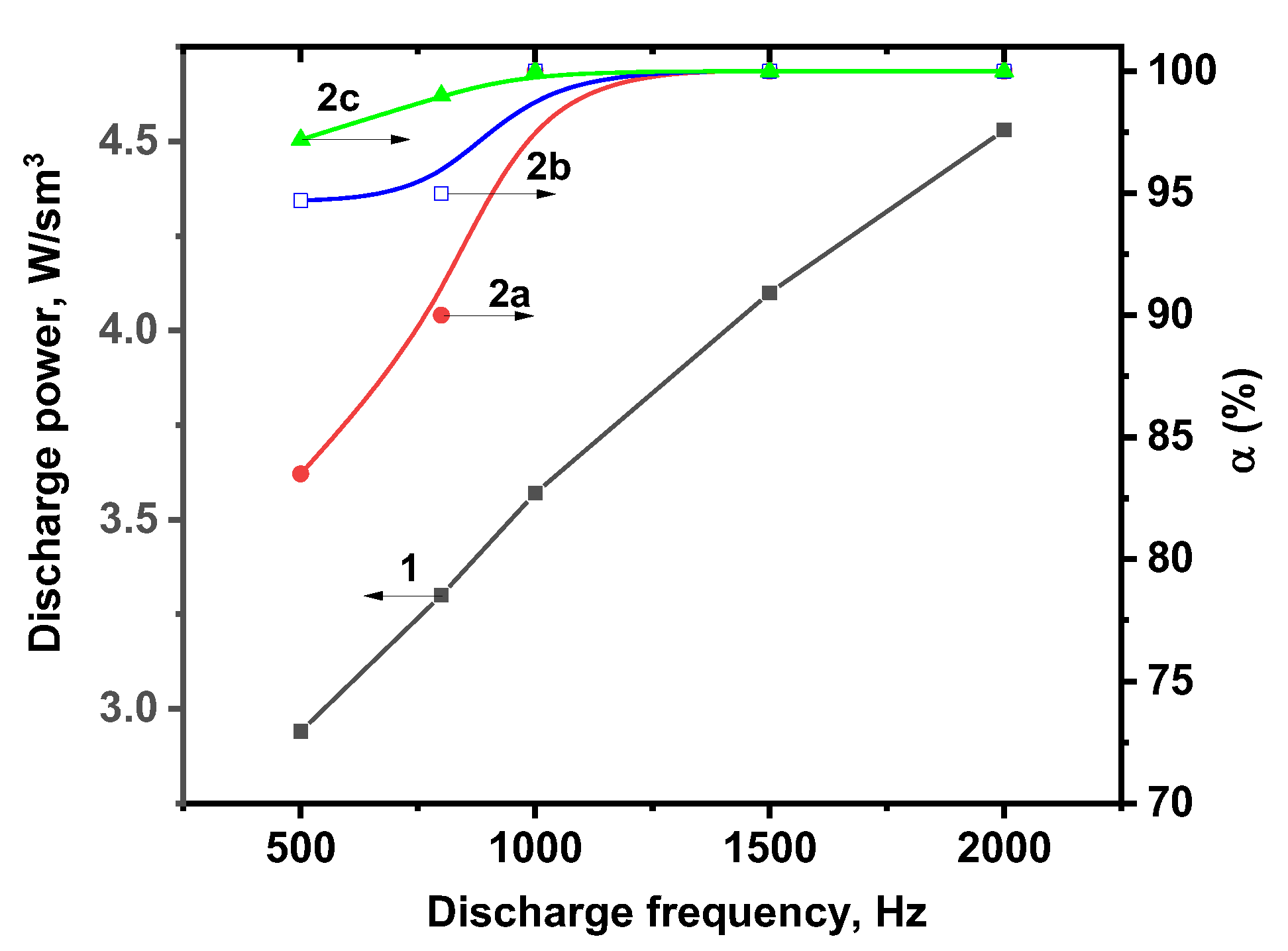
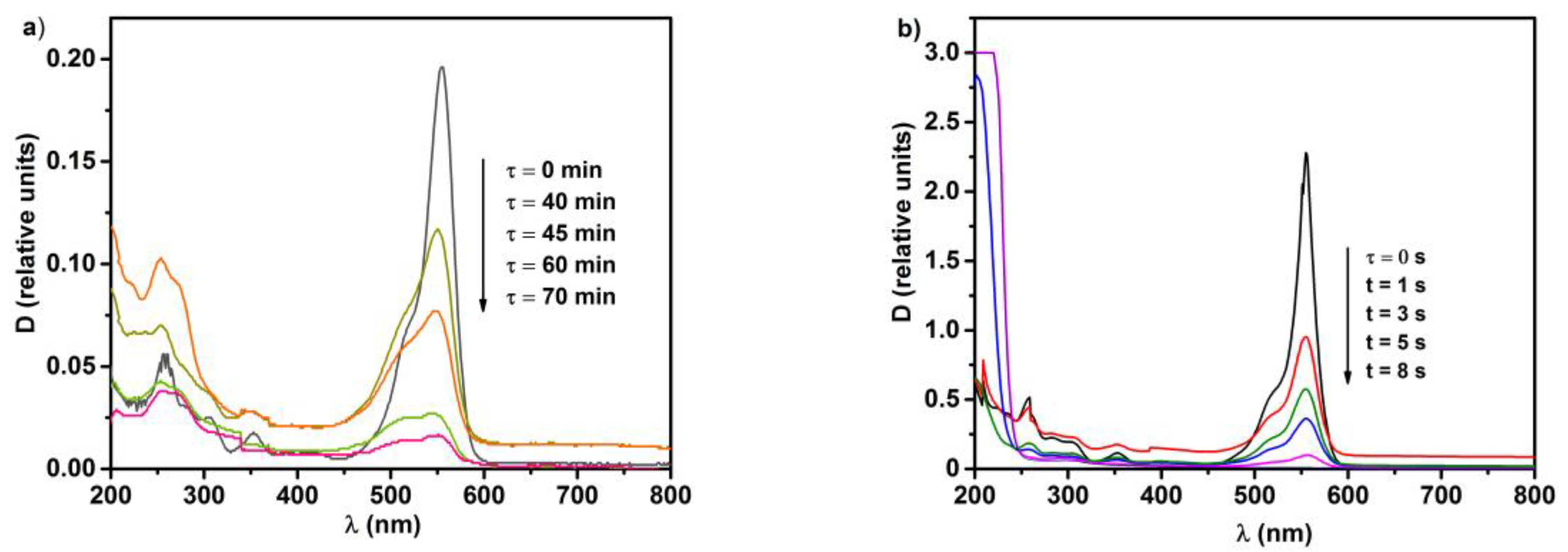
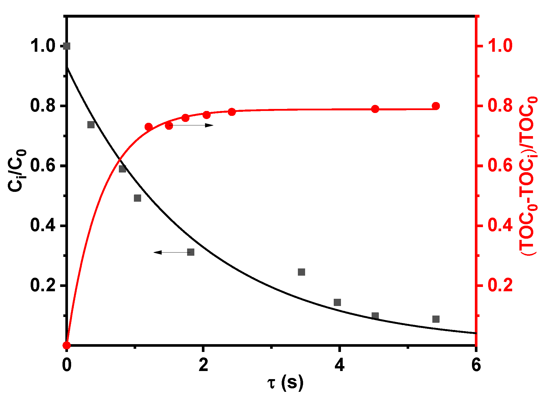
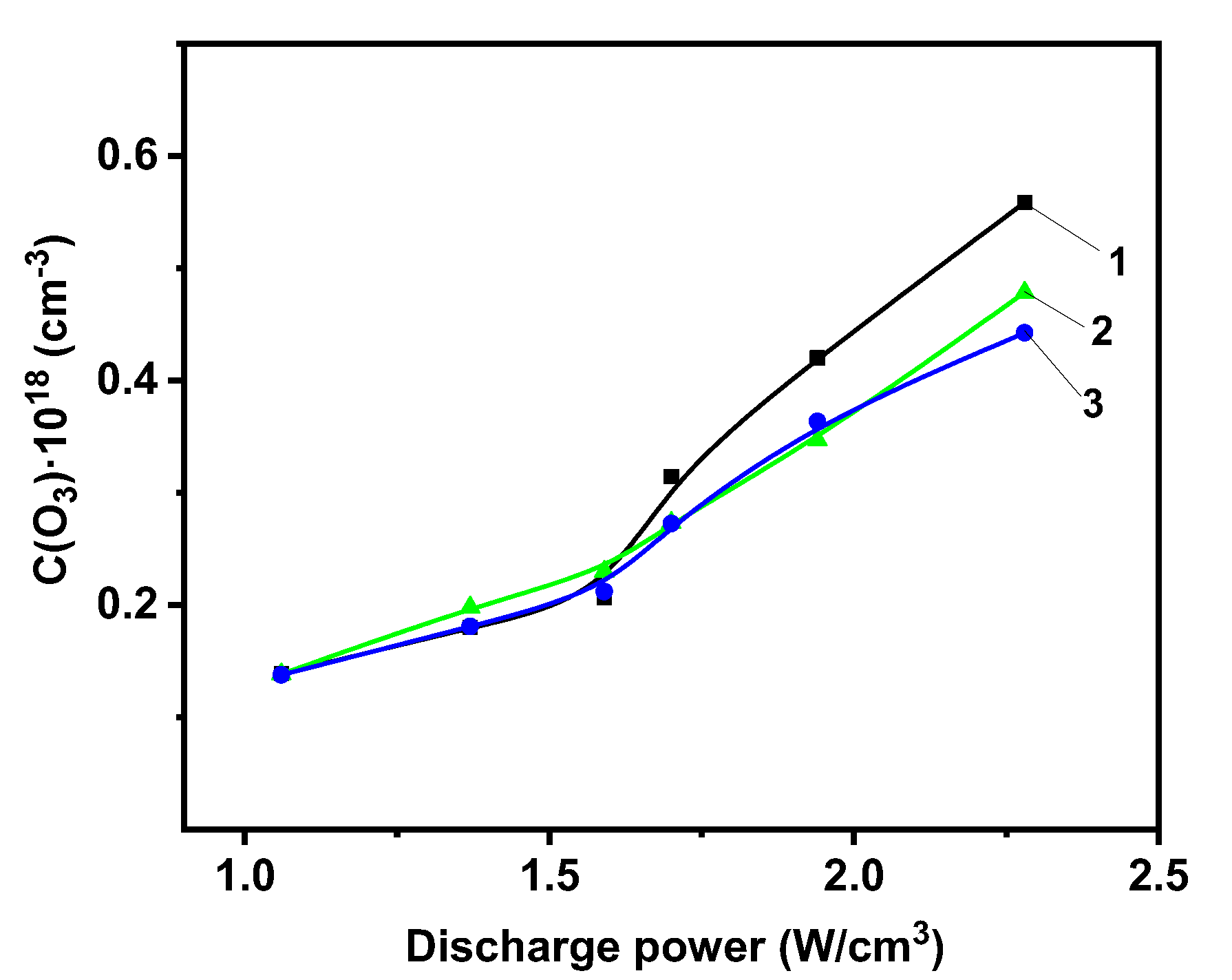
2.2. Photolytic and Plasmolytic Characterization

Kinetics and efficiency of the RhB destruction in the photolysis and plasmolysis processes are shown in Figure 4 and Figure 5, respectively. From these figures, it can be seen that the destruction of Rhodamine B was significantly more efficient when using the combined plasma–catalytic process. Note that both in photocatalytic and combined plasma–catalytic processes the dye destruction efficiency increased successively in the series of photocatalysts TiO2-PMM, TiO2-PMMH and TiO2-PAMMH. This is primarily due to an increase in the total pore volume and the size of the TiO2 crystallites (Table 1), which determines the e + h+ pair regeneration rate [43].
The photocatalytic experimental data are processed using the first-order kinetic model [44]. In order to accurately compare the rate constants with the plasmolysis processes, we proceeded from the following suppositions. Experimental data describing the kinetic regularities in DBD plasma in the most common form can be expressed in terms of cylindrical coordinates:
z [ D i n i z ] + 1 r d r [ r D i n i r ] z ( V n i ) + W = 0
where z and r are the longitudinal and radial coordinates, respectively; ni is the initial, the concentration of RhB, V is the linear flow rate, Di is the diffusion coefficient and W is the rate of RhB-related chemical processes.
The characteristic value of the diffusion coefficient (D) for organic compounds in water was 10−5 cm2/s [45]. Characteristic processing times were 10 s for DBD and 6000 s for photocatalytic processes, whereas for diffusion processes they amounted to 107 s. Therefore, diffusion processes could be neglected in the considered systems. Assuming that RhB in the processes under study was subject to destruction, the change in the concentration of the dye in the solution could be described by the equation:
V d n a d z = W a ,
where na and Wa are the average concentration and the average RhB decomposition rate, respectively.
n a = 2 ( r 2 2 r 1 2 ) r 1 r 2 n i r d r
W a = 2 ( r 2 2 r 1 2 ) r 1 r 2 W r d r
where r1 and r2 are the external and internal radii of the fluid layer.
For boundary conditions na = nin (z = 0) and the assumption that the RhB decomposition rate is described by a first-order kinetic equation and is an irreversible process, Equation (10) also acquires the form corresponding to the first kinetic order equation:
n c = n i n exp ( K t ) ,
where nin is the initial concentration of the dye in the solution, µmol/L, K is the rate constant, s−1, and t is the processing time, s. Effective rate constants for the three studied processes are presented in Table 2.
From Table 2 it can be seen that the RhB degradation rate constant was significantly smaller in the photocatalytic process compared to DBD plasma. Comparison of the effect of photocatalysts on the rate of destruction shows that for both purely photocatalytic process and combined plasma–catalytic process, the catalytic effect increased in the series TiO2-PMM, TiO2-PMMH and TiO2-PAMMH. Note that rate constants for the photocatalytic processes of RhB decomposition with our catalytic materials were significantly larger than those known in the literature: (0.8–1.6)·10−3 s−1 [46].
Evaluation of the energy cost of RhB destruction (Y50%, g/(kW·h), Table 2) was carried out according to the following equation [47]:
Y 50 % = C i V α P t 100 ,
where Ci is the initial concentration of the dye in the solution, g/L; V is the volume of the treated solution, L; P is the power expended in the process of destruction, kW, and t is the processing time, h.
Table 2 shows that the energetic efficiency decreased with an increasing degree of RhB degradation (Figure 6), which was associated with a decrease in the concentration of the dye, and also the reduced probability of an interaction of active particles formed in the solution and UV photons with RhB and intermediate products of its decomposition.
The obtained results suggest a possible reduction in energy consumption when using a combined plasma–photocatalytic effect. To this end, we studied the effect of the discharge current frequency on the expended power in the discharge and the efficiency of the RhB decomposition, as shown in Figure 7.
As can be seen from the data presented in Figure 7, at current frequencies above 1500 Hz the discharge burning conditions were met, allowing for the complete removal of the dye from aqueous solutions. It should be noted that the presence of photocatalysts in the system greatly reduced the energy consumption while maintaining the high degrees of degradation. Thus, under the same treatment conditions (the expended power in the discharge was 3 W/cm3 and the current frequency was 500 Hz), the efficiency of the purification process in the presence of photocatalysts was 20% higher compared to DBD.
Apart from reducing energy costs, the plasma–catalytic method allows for more profound destruction of the dye compared to UV photolysis. Figure 8 shows the evolution of UV-Vis absorption spectra for RhB which, being a chromophore, is characterized by three major absorption bands in an aqueous solution at 554, 340 and 259 nm [48]; a decrease in the latter indicates degradation of the aromatic part of the dye. The most important observation when comparing spectra in Figure 8 is the emergence of intense bands around 200 nm in the DBD spectrum as the processing time increased. These bands were characteristic for carboxylic acids (n→π* transition at λmax = 204 nm) [49], which indicates destructive oxidative processes leading to the rupture of the aromatic rings of the dye and the formation of simpler organic compounds such as carboxylic acids.
To quantify the destruction of the studied pollutant, experiments were carried out to assess changes of the total organic carbon (TOC) content and the concentration of carbon oxides (CO and CO2). Aqueous solutions of Rhodamine B were studied with an initial concentration of 40 mg/L. The solutions were processed in DBD with a TiO2-PAMMH catalyst at optimal processing parameters. These conditions were chosen because the TiO2-PAMMH catalyst in DBD shows the maximum dye decomposition efficiency at the minimum energy cost. As can be seen from Figure 9, the maximum degree of decomposition under these experimental conditions was 91% and the degree of mineralization was 80%. The decomposition process initially formed intermediate organic compounds with a lower molecular weight (such as alcohols and carboxylic acids), which were subsequently oxidized to CO, CO2 and H2O, which confirmed a high degree of mineralization. The measurement of the content of carbon oxides in the system made it possible to assess the convergence of the carbon balance (i.e., the completeness of the determination of intermediate compounds), which was determined by the formula:
δ = Y p r Y i n
where Ypr is the carbon content in the system after the processing (decomposition products in the liquid and gas phases), taking into account the incompleteness of RhB destruction, and Yin is the carbon content in the RhB stock solution. Carbon oxides were detected only in the gas phase, which could be explained by the low pH < 4 of the solutions after DBD treatment. The CO and CO2 concentrations were around 16.6 mmol/m3 and 21.2 mmol/m3 for a carrier gas flow rate of 0.5 L/min (8.3·10−6 m3/s), which corresponded to 1.43·10−7 mol/s and 1.82·10−7 mol/s, respectively. The assessment of the carbon balance showed that the total yield of carbon oxides was at least 90% of the TOC in the system, which confirmed the experimental TOC results.
The results allowed us to suggest a possible mechanism for the decomposition of RhB, which proceeded through a series of intermediate stages. It included the breaking of aromatic rings with the formation of aldehydes, alcohols, and carboxylic acids, which were easily oxidized and were converted into CO and CO2 by the action of active particles (Figure 10).
Ozone is one of the main oxidizing agents formed in the barrier discharge [50], which is also reflected in the proposed destruction mechanism in Figure 10. The maximum dye destruction efficiencies were observed at high DBD powers. This suggests that the optimal conditions for the formation of ozone were precisely fulfilled for these parameters. To assess the contribution of ozone to the RhB degradation, the ozone concentration in the DBD process was measured in model aqueous solutions with and without RhB and a photocatalyst, see Figure 11.
The ozone concentration increased with the discharge power, as measured for the reference sample 1. For a higher discharge power a part of the ozone was consumed for the RhB destruction. The contribution of ozone to the RhB oxidation process can be quantified according to the equation:
3 C 28 H 31 Cl N 2 O 3 + 73 O 3 = 84 C O 2 + 42 H 2 O + 3 C l + 6 N O 3 + 9 H + ,
Hence, about 24 moles of O3 are needed for the complete oxidation of 1 mol of RhB. According to the data presented in Figure 11, the maximum decrease in ozone concentration during dye oxidation was 0.12 × 1018 cm−3, which corresponded at a liquid flow rate of 0.5 mL/s to 100 μmol/s. When the dye content in the system was equal to 43 μmol/s, its total oxidation required 1032 μmol O3. Therefore, other active particles formed in the discharge zone of the reactor made a significant contribution to the decomposition of the dye besides the ozone. It should also be noted that the introduction of a catalyst into the DBD reactor did not affect the ozone formation and destruction processes in the discharge power range of 1.1–2.1 W/cm3 (Figure 11). Only at high values of the discharge power, the ozone concentration in the liquid decreased by approximately 10% in the presence of a catalyst.

3. Materials and Methods

3.1. Materials

Rhodamine B (RhB, C28H31ClN2O3, M = 479.02 g/mol; Figure 12), which belongs to the group of fluorescent dyes [51], was chosen as a model pollutant. RhB is highly soluble in water and is highly stable towards light [52].

3.2. Methods

3.2.1. Preparation of Photocatalysts Based on TiO2-Pillared Montmorillonite

Montmorillonite used in this work was extracted from Daş Salahlı bentonite [53] by the sedimentation method and possessed the following chemical composition, wt %: SiO2—58.22; TiO2—1.05; Al2O3—13.87; Fe2O3—5.41; FeO—0.20; CaO—2.51; MgO—3.16; Na2O—1.76; K2O—0.24 and loss upon calcination—13.58. The main “impurity” minerals are cristobalite, quartz, plagioclase, calcite and gypsum. The composition of exchangeable cations (mEq/100 g) was as follows: Ca2+—24.69; Mg2+—22.74; (Na+ + K+)—51.33 and total—98.76.
Preparation of TiO2-pillared montmorillonite was carried out in accordance with the three following methods: I) intercalation of titanium hydroxocomplexes [54]; II) hydrothermal activation of the intercalation of titanium hydroxocomplexes [55]; III) both the preliminary mechanical treatment of the layered substrate [51] and hydrothermal activation of the intercalation of titanium hydroxocomplexes.
Intercalating solutions containing titanium polycations were prepared at room temperature by hydrolysis of titanium chloride according to Ref. [54]. In detail, 6 M solution of HCl was treated with TiCl4 (Sigma-Aldrich Rus, Moscow, Russia) drop by drop to obtain solutions with a Ti4+ concentration of 4.92 M (a concentration of 4.92 M was the upper limit of sol formation). For further intercalation, the solutions were diluted by slow addition of deionized water to obtain solutions with a residual Ti4+ concentration of 0.56 M. Prior to use, intercalating solutions were subjected to aging for 3 h at 20 °C, resulting in the formation of titanium polyhydroxocomplexes.
According to method I, the intercalation of montmorillonite by titanium hydroxocomplexes was carried out using ion exchange in a 1% aqueous suspension with a drop-by-drop addition of an intercalating solution (10 mmol of Ti4+/g MM) and vigorous stirring with a magnetic stirrer for 3 h at 20 °C. According to method II, the suspension of MM and the intercalating solution was subjected to hydrothermal treatment for 5 h at a temperature of 115 °C and a pressure of 170 kPa using a pressurized reactor made from fluoroplastic glass. After 12 h of coagulation at room temperature, the suspension was washed from Cl ions, centrifuged and dried in a drying cabinet at 60 °C. According to method III, the original MM was treated in an energy-stressed planetary centrifugal mill AGO-2C (Novice, Novosibirsk, Russia). The mechanically activated MM is denoted as AMM. High-strength zirconium grinding bodies were used at a constant rotor speed of 1500 rpm; the mass ratio of MM to grinding bodies was 7.5:1. The milling improves textural properties [32]. Intercalated materials were prepared according to method II.
Pillared materials were obtained by annealing intercalated samples in a furnace at a temperature of 500 °C for 3 h.

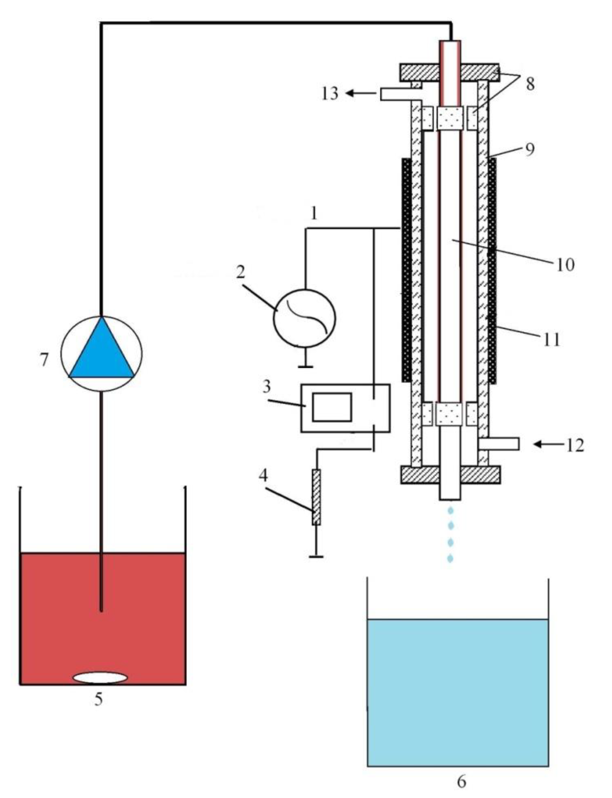
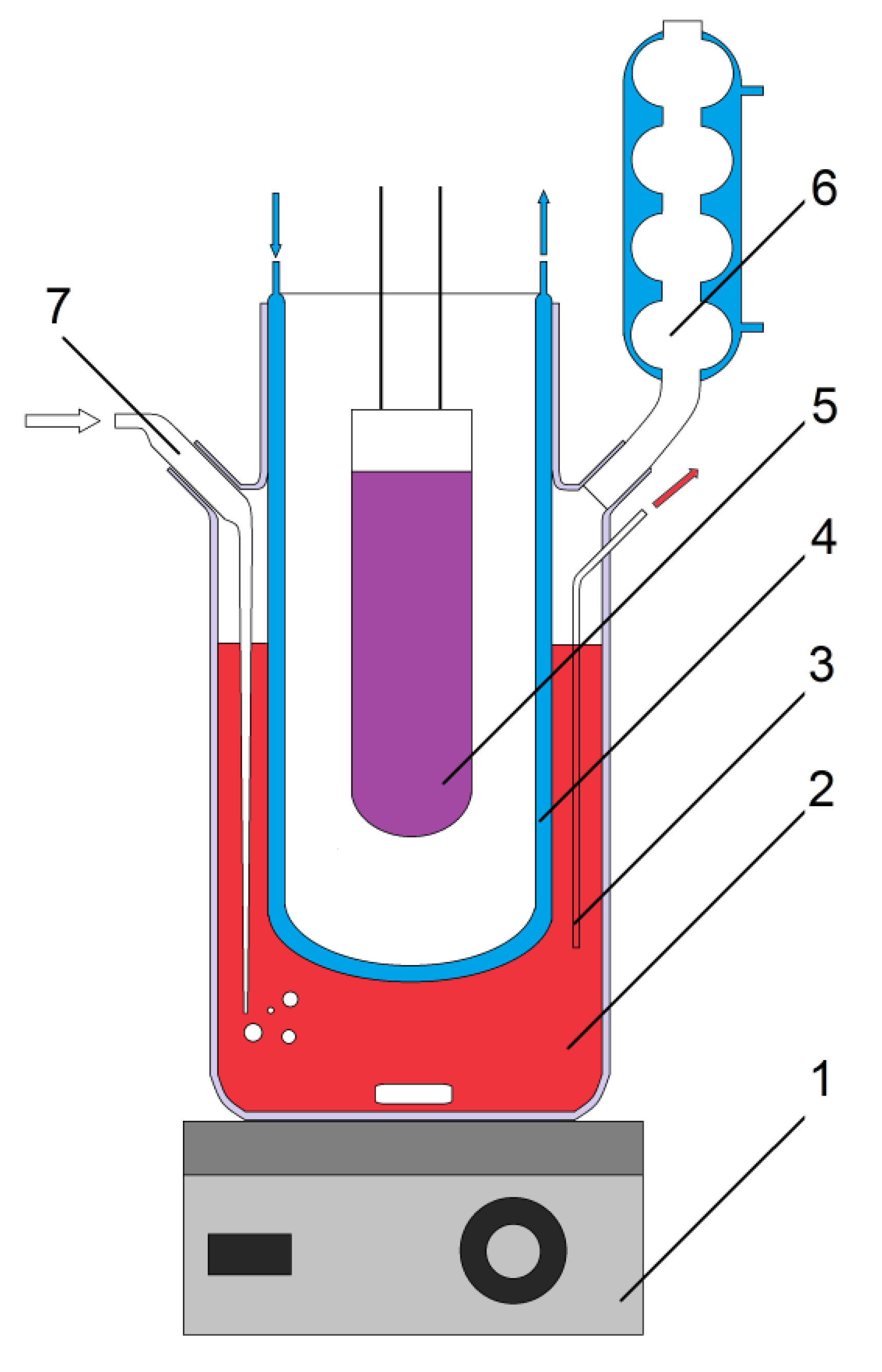
3.2.2. Description of Experimental Installations

A scheme of the DBD reactor is shown in Figure 13 [16]. The reactor is a coaxial system consisting of an outer Pyrex tube, 12 mm in diameter, which is the dielectric barrier of the discharge, and an inner aluminum-alloy electrode with a diameter of 8 mm. The outer electrode is an aluminum foil, uniformly deposited on the outer surface of the glass tube. The discharge zone was 12 cm long. The solution flows along the outer side of the electrode, in the volume where the gas flows. A hydrophobic glass fabric with a thickness of 1 mm was applied to the inner electrode, providing a film flow mode of the model solution in the system.
The volumetric flow rate of the model solution (initial RhB concentration of 40 mg/L) varied in the range of 0.15–1.0 mL/s. The time of the fluid contact (tK) with the discharge zone was determined by the formula:
t K = p D h L Q
where D is the thickness of the hydrophilic material, h is the thickness of the solution film, Q is the volumetric flow rate of the solution and L is the length of the discharge zone. The film thickness of the fluid was calculated assuming a smooth laminar flow in the field of gravity [56]:
h = ( 3 n Q g p D ) 1 / 3
where n is the kinematic viscosity of the fluid and g is the gravitational constant.
The discharge was excited by a high-voltage transformer. The voltage was monitored using a high-voltage probe, and the discharge current was determined by the voltage drop across the resistor (100 Ohm) connected in series to the ground circuit. Both signals were simultaneously controlled by a two-channel digital oscilloscope GW Instek GDS-2072 (Good Will Instrument CO. LTD, New Taipei City, Taiwan). The voltage in the system was changed from 6 to 13 kV. The discharge current in the experiments was 0.1–0.8 mA. The frequency of the discharge current varied in the range 500–2000 Hz, and the discharge power in the studied frequency range was 20–180 W. Voltage-current characteristics and discharge power, as well as the effect of the frequency of the discharge current on the physical characteristics of the plasma, are given in [15].
The plasma-forming gas was oxygen (technical grade, 99.7%), which was fed into the system against the fluid flow with a volume flow rate of 1–3 cm3/s.
The photocatalytic reactor is shown in Figure 14. The photocatalytic activity of the TiO2-pillared MM samples was derived from the RhB destruction rate in an aqueous solution. The source of UV radiation was a high-pressure 250 W mercury lamp (Royal Philips Electronics, Amsterdam, The Netherlands) with maximum emission at 365 nm. The lamp was located in a water-cooled quartz vessel and placed in the center of the reactor with a volume of 800 mL. A magnetic stirrer provided an effective mixing of the reaction volume. The solution was purged with a constant air flow to ensure a steady concentration of dissolved oxygen. In each experiment, the synthesized photocatalyst (1 g/L) was added to 500 mL of the RhB solution (40 mg/L). A homogeneous reaction mixture was obtained after stirring up to 100 min at 25 °C.
The RhB concentration in the solution was determined photometrically before and during the process in the photocatalytic reactor or the DBD reactor. The optical density at the absorption maximum of RhB at λmax = 554 nm was measured on a Hitachi U-2001 spectrophotometer (wavelength range 200–800 nm). The RhB absorption maximum was determined from UV-Vis spectra of an aqueous solution (Figure 8) and corresponds to n→π* transitions of the C=N and C=O groups [57].
To eliminate any effect of sorption processes, the photocatalytic reactor and the DBD reactor were equilibrated for 30 min [31] and 5 min, respectively, before starting the process. The reactor vessels were thoroughly cleaned between experiments.
The destruction (α) of RhB was evaluated from the discoloration of the solution:
α ( % ) = A 0 A A 0 100
where A0 and A are the initial and final absorption, respectively, of the Rhodamine B solution at λmax = 554 nm.
The ozone concentration was measured in an external cell from absorption measurements at 253.7 nm, close to the maximum of the Hartley ozone absorption band. An AvaSpec-2048FT-2 monochromator (Avantes BV, Apeldoorn, The Netherlands) with digital spectrum recording and a low-pressure Hg lamp were used. The ozone concentration was calculated from the absorption cross section 1.418 × 10⁻¹⁸ cm2 [58].
The CO and CO2 content in the gas phase at the outlet of the reactor were estimated by gas chromatography (Chromatech-5000 gas chromatograph, Chromatek, Yoshkar-Ola, Mariy El, Russia) with a methanator and a plasma ionization detector [59].

4. Conclusions

In this study, the degradation of the water-soluble dye Rhodamine B was investigated using photocatalytic, plasma and combined plasma–photocatalytic processes with the use of TiO2-pillared montmorillonite as a nanoscale photocatalyst. The catalysts were prepared by intercalation of titanium hydroxocomplexes, including hydrothermal activation of the process and preliminary mechanical treatment of the layered substrate. A 100% degradation of Rhodamine B was achieved in 8 s using a DBD plasma treatment in the presence of photocatalysts with a process energetic efficiency of 2.27 g/kWh. Over the same time, conventional plasmolysis removed 94% of the dye (1.21 g/kWh). UV photocatalytic degradation allowed for the removal of 92% RhB after 100 min of irradiation (0.24 g/kWh). Thus, a synergistic effect was observed (both in terms of energetic efficiency and process rate) for the combined use of the plasma and photocatalytic processes. The reaction of the dye destruction was described by a first order kinetic equation and the largest observed rate constant for the reaction of destruction was 0.6910 s−1. In addition, in terms of complete purification of aqueous solutions from organic pollutants, the advantage of combined DBD plasma and TiO2-pillared montmorillonite treatment was based on more profound destructive processes leading to the formation of simple organic compounds such as carboxylic acids as compared with UV photolysis. It is shown that improved textural properties of the nanophotocatalyst (specific surface area and total pore volume) and an increase in the size of the TiO2 crystallites upon hydrothermal treatment allows for more efficient removal of the dye from aqueous solutions regardless of the type of the external influence.

Author Contributions

Conceptualization, M.F.B., A.A.G., N.L.O.; data curation, A.A.G., N.L.O., G.I.G.; formal analysis, M.F.B., A.A.G., N.L.O., G.I.G., S.P.K.; investigation, A.A.G., N.L.O., G.I.G., N.V.Z.; methodology, A.A.G., N.L.O., G.I.G., N.V.Z.; project administration, M.F.B.; resources, A.A.G., M.F.B.; software, A.A.G., G.I.G., N.L.O., S.P.K.; supervision, M.F.B., K.W.K.; validation, M.F.B., A.A.G., K.W.K.; visualization, A.A.G., S.P.K.; writing—original draft, A.A.G., N.L.O.; writing—review & editing, M.F.B., A.A.G., K.W.K. All authors have read and agreed to the published version of the manuscript.

Funding

This research was funded by the Ministry of Science and Higher Education of the Russian Federation grant number [FZZW-2020-0010] and the Russian Foundation for Basic Research grant number [18-08-01239]. The APC was funded by the University of Bern, Switzerland.

Conflicts of Interest

The authors declare no conflict of interest.

References

  1. Thao, N.T.; Nga, H.T.P.; Vo, N.Q.; Nguyen, H.D.K. Advanced oxidation of rhodamine B with hydrogen peroxide over Zn–Cr layered double hydroxide catalysts. J. Sci. Adv. Mater. Devices 2017, 2, 317–325. [Google Scholar] [CrossRef]
  2. Khandare, R.V.; Govindwar, S.P. Phytoremediation of textile dyes and effluents: Current scenario and future prospects. Biotechnol. Adv. 2015, 33, 1697–1714. [Google Scholar] [CrossRef]
  3. Lai, C.-L.; Lin, K.-S. Sludge conditioning characteristics of copper chemical mechanical polishing wastewaters treated by electrocoagulation. J. Hazard. Mater. 2006, 136, 183–187. [Google Scholar] [CrossRef]
  4. Lefebvre, O.; Moletta, R. Treatment of organic pollution in industrial saline wastewater: A literature review. Water Res. 2006, 40, 3671–3682. [Google Scholar] [CrossRef] [PubMed]
  5. Verma, P.; Samanta, S.K. Microwave-enhanced advanced oxidation processes for the degradation of dyes in water. Environ. Chem. Lett. 2018, 16, 969–1007. [Google Scholar] [CrossRef]
  6. Dhanalakshmi, J.; Padiyan, D.P. Photocatalytic degradation of methyl orange and bromophenol blue dyes in water using sol-gel synthesized TiO2 nanoparticles. Mater. Res. Express 2017, 095020. [Google Scholar] [CrossRef]
  7. Hou, X.; Shen, W.; Huang, X.; Ai, Z.; Zhang, L. Ascorbic acid enhanced activation of oxygen by ferrous iron: A case of aerobic degradation of rhodamine B. J. Hazard. Mater. 2016, 308, 67–74. [Google Scholar] [CrossRef] [PubMed] [Green Version]
  8. Kurade, M.B.; Waghmode, T.R.; Khandare, R.V.; Jeon, B.-H.; Govindwar, S.P. Biodegradation and detoxification of textile dye Disperse Red 54 by Brevibacillus laterosporus and determination of its metabolic fate. J. Biosci. Bioeng. 2016, 121, 442–449. [Google Scholar] [CrossRef]
  9. Reza, K.M.; Kurny, A.; Gulshan, F. Parameters affecting the photocatalytic degradation of dyes using TiO2: A review. Appl. Water Sci. 2017, 7, 1569–1578. [Google Scholar] [CrossRef] [Green Version]
  10. Shanker, U.; Rani, M.; Jassal, V. Degradation of hazardous organic dyes in water by nanomaterials. Environ. Chem. Lett. 2017, 15, 623–642. [Google Scholar] [CrossRef]
  11. Bilińska, L.; Gmurek, M.; Ledakowicz, S. Comparison between industrial and simulated textile wastewater treatment by AOPs—Biodegradability, toxicity and cost assessment. Chem. Eng. J. 2016, 306, 550–559. [Google Scholar] [CrossRef] [Green Version]
  12. Natarajan, T.S.; Thomas, M.; Natarajan, K.; Bajaj, H.C.; Tayade, R.J. Study on UV-LED/TiO2 process for degradation of Rhodamine B dye. Chem. Eng. J. 2011, 169, 126–134. [Google Scholar] [CrossRef]
  13. Neves, T.M.; Frantz, T.S.; do Schenque, E.C.C.; Gelesky, M.A.; Mortola, V.B. An investigation into an alternative photocatalyst based on CeO2/Al2O3 in dye degradation. Environ. Technol. Innov. 2017, 8, 349–359. [Google Scholar] [CrossRef]
  14. Gusev, G.I.; Gushchin, A.A.; Grinevich, V.I.; Osti, A.A.; Izvekova, T.V.; Kvitkova, E.Y. Regeneration of natural sorbents contaminated with oil products in dielectric barrier discharge plasma. Izv. Vyss. Uchebnykh Zaved. Seriya Khimiya Khimicheskaya Tekhnol. 2017, 60, 72–76. [Google Scholar] [CrossRef]
  15. Gushchin, A.A.; Grinevich, V.I.; Gusev, G.I.; Kvitkova, E.Y.; Rybkin, V.V. Removal of Oil Products from Water Using a Combined Process of Sorption and Plasma Exposure to DBD. Plasma Chem. Plasma Process. 2018, 38, 1021–1033. [Google Scholar] [CrossRef]
  16. Gushchin, A.A.; Grinevich, V.I.; Shulyk, V.Y.; Kvitkova, E.Y.; Rybkin, V.V. Destruction Kinetics of 2,4 Dichlorophenol Aqueous Solutions in an Atmospheric Pressure Dielectric Barrier Discharge in Oxygen. Plasma Chem. Plasma Process. 2018, 38, 123–134. [Google Scholar] [CrossRef]
  17. Hama Aziz, K.H.; Mahyar, A.; Miessner, H.; Mueller, S.; Kalass, D.; Moeller, D.; Khorshid, I.; Rashid, M.A.M. Application of a planar falling film reactor for decomposition and mineralization of methylene blue in the aqueous media via ozonation, Fenton, photocatalysis and non-thermal plasma: A comparative study. Process Saf. Environ. Prot. 2018, 113, 319–329. [Google Scholar] [CrossRef]
  18. Lu, N.; Hui, Y.; Shang, K.; Jiang, N.; Li, J.; Wu, Y. Diagnostics of Plasma Behavior and TiO2 Properties Based on DBD/TiO2 Hybrid System. Plasma Chem. Plasma Process. 2018, 38, 1239–1258. [Google Scholar] [CrossRef]
  19. Ochiai, T.; Nakata, K.; Murakami, T.; Morito, Y.; Hosokawa, S.; Fujishima, A. Development of an air-purification unit using a photocatalysis-plasma hybrid reactor. Electrochemistry 2011, 79, 838–841. [Google Scholar] [CrossRef] [Green Version]
  20. Tichonovas, M.; Krugly, E.; Racys, V.; Hippler, R.; Kauneliene, V.; Stasiulaitiene, I.; Martuzevicius, D. Degradation of various textile dyes as wastewater pollutants under dielectric barrier discharge plasma treatment. Chem. Eng. J. 2013, 229, 9–19. [Google Scholar] [CrossRef]
  21. Palau, J.; Assadi, A.A.; Penya-Roja, J.M.; Bouzaza, A.; Wolbert, D.; Martínez-Soria, V. Isovaleraldehyde degradation using UV photocatalytic and dielectric barrier discharge reactors, and their combinations. J. Photochem. Photobiol. A Chem. 2015, 299, 110–117. [Google Scholar] [CrossRef] [Green Version]
  22. Wang, T.C.; Lu, N.; Li, J.; Wu, Y. Plasma-TiO2 catalytic method for high-efficiency remediation of p-nitrophenol contaminated soil in pulsed discharge. Environ. Sci. Technol. 2011, 45, 9301–9307. [Google Scholar] [CrossRef] [PubMed]
  23. Neyts, E.C. Plasma-Surface Interactions in Plasma Catalysis. Plasma Chem. Plasma Process. 2016, 36, 185–212. [Google Scholar] [CrossRef]
  24. Attri, P.; Tochikubo, F.; Park, J.H.; Choi, E.H.; Koga, K.; Shiratani, M. Impact of Gamma rays and DBD plasma treatments on wastewater treatment. Sci. Rep. 2018, 8. [Google Scholar] [CrossRef] [PubMed] [Green Version]
  25. Assadi, A.A.; Bouzaza, A.; Vallet, C.; Wolbert, D. Use of DBD plasma, photocatalysis, and combined DBD plasma/photocatalysis in a continuous annular reactor for isovaleraldehyde elimination—Synergetic effect and byproducts identification. Chem. Eng. J. 2014, 254, 124–132. [Google Scholar] [CrossRef] [Green Version]
  26. Guaitella, O.; Thevenet, F.; Puzenat, E.; Guillard, C.; Rousseau, A. C2H2 oxidation by plasma/TiO2 combination: Influence of the porosity, and photocatalytic mechanisms under plasma exposure. Appl. Catal. B Environ. 2008, 80, 296–305. [Google Scholar] [CrossRef]
  27. Yamashita, H.; Li, H. Nanostructured Photocatalysts: Advanced Functional Materials; Springer: Berlin, Germany, 2016. [Google Scholar] [CrossRef]
  28. Szczepanik, B. Photocatalytic degradation of organic contaminants over clay-TiO2 nanocomposites: A review. Appl. Clay Sci. 2017, 141, 227–239. [Google Scholar] [CrossRef]
  29. Vicente, M.A.; Gil, A.; Bergaya, F. Pillared Clays and Clay Minerals, 2nd ed.; Developments in Clay Science; Elsevier Ltd.: Amsterdam, The Netherlands, 2013. [Google Scholar] [CrossRef]
  30. Zhao, B.X.; Dang, L.P.; Zhang, X.L.; Yang, N.; Sun, Y.Y. Preparation of TiO2-Pillared Montmorillonite as Photocatalyst and Photocatalytic Degradation of Methyl Orange. Appl. Mech. Mater. 2012, 190–191, 534–538. [Google Scholar] [CrossRef]
  31. Butman, M.F.; Ovchinnikov, N.L.; Karasev, N.S.; Kochkina, N.E.; Agafonov, A.V.; Vinogradov, A.V. Photocatalytic and adsorption properties of TiO2-pillared montmorillonite obtained by hydrothermally activated intercalation of titanium polyhydroxo complexes. Beilstein J. Nanotechnol. 2018, 9, 364–378. [Google Scholar] [CrossRef] [Green Version]
  32. Ovchinnikov, N.L.; Arbuznikov, V.V.; Kapinos, A.P.; Belozerov, A.G.; Butman, M.F. Effect of mechanical activation of montmorillonite on the intercalation efficiency of polyhydroxyaluminum cations in the formation of pillar structure. Nanotechnol. Russ. 2015, 10, 254–260. [Google Scholar] [CrossRef]
  33. Mandlimath, T.R.; Moliya, A.; Sathiyanarayanan, K.I. General Synthesis of Bi2Mo3O12 and Bi2−xRExMo3O12 nanorods (RE = Eu3+ and Pr3+ and x = 0.07–0.3): Improved photocatalytic activity towards the degradation of Rhodamine B dye under visible light. Appl. Catal. A Gen. 2016, 519, 34–47. [Google Scholar] [CrossRef]
  34. Al-Shamiri, H.A.; Kana, M.A. Laser performance and photostability of Rhodamin B in solid host matrices. Appl. Phys. B 2010, 101, 129–135. [Google Scholar] [CrossRef]
  35. Asano, M.; Doi, M.; Baba, K.; Taniguchi, M.; Shibano, M.; Tanaka, S.; Sakaguchi, M.; Takaoka, M.; Hirata, M.; Yanagihara, R.; et al. Bio-imaging of hydroxyl radicals in plant cells using the fluorescent molecular probe rhodamine B hydrazide, without any pretreatment. J. Biosci. Bioeng. 2014, 118, 98–100. [Google Scholar] [CrossRef] [PubMed]
  36. Gong, Y.J.; Zhang, X.B.; Mao, G.J.; Su, L.; Meng, H.M.; Tan, W.; Feng, S.; Zhang, G. A unique approach toward near-infrared fluorescent probes for bioimaging with remarkably enhanced contrast. Chem. Sci. 2016, 7, 2275–2285. [Google Scholar] [CrossRef] [PubMed] [Green Version]
  37. Li, J.; Li, S.; Wei, X.; Tao, H.; Pan, H. Molecularly imprinted electrochemical luminescence sensor based on signal amplification for selective determination of trace gibberellin A3. Anal. Chem. 2012, 84, 9951–9955. [Google Scholar] [CrossRef] [PubMed]
  38. Baviskar, P.K.; Zhang, J.B.; Gupta, V.; Chand, S.; Sankapal, B.R. Nanobeads of zinc oxide with rhodamine B dye as a sensitizer for dye sensitized solar cell application. J. Alloys Compd. 2012, 510, 33–37. [Google Scholar] [CrossRef]
  39. Dire, D.J.; Wilkinson, J.A. Acute exposure to rhodamine B. J. Toxicol. Clin. Toxicol. 1987, 25, 603–607. [Google Scholar] [CrossRef]
  40. Langford, J.I.; Wilson, A.J.C. Scherrer after sixty years: A survey and some new results in the determination of crystallite size. J. Appl. Crystallogr. 1978, 11, 102–113. [Google Scholar] [CrossRef]
  41. Sing, K.S.W.; Everett, D.H.; Haul, R.A.W.; Moscou, L.; Pierotti, R.A.; Rouquérol, J.; Siemieniewska, T. Physical and biophysical chemistry division commission on colloid and surface chemistry including catalysis. Pure Appl. Chem. 1985, 57, 603–619. [Google Scholar] [CrossRef]
  42. Ninness, B.J.; Bousfield, D.W.; Tripp, C.P. Formation of a thin TiO2 layer on the surfaces of silica and kaolin pigments through atomic layer deposition. Colloids Surf. A 2003, 214, 195–204. [Google Scholar] [CrossRef]
  43. Son, H.-J.; Wang, X.; Prasittichai, C.; Jeong, N.C.; Aaltonen, T.; Gordon, R.G.; Hupp, J.T. Glass-encapsulated light harvesters: More efficient dye-sensitized solar cells by deposition of self-aligned, conformal, and self-limited silica layers. J. Am. Chem. Soc. 2012, 134, 9537–9540. [Google Scholar] [CrossRef] [PubMed]
  44. Damardji, B.; Khalaf, H.; Duclaux, L.; David, B. Preparation of TiO2-pillared montmorillonite as photocatalyst Part II. Photocatalytic degradation of a textile azo dye. Appl. Clay Sci. 2009, 45, 98–104. [Google Scholar] [CrossRef]
  45. Reid, R.C.; Prausnitz, J.M.; Sherwood, T.K. The Properties of Gases and Liquids, 4th ed.; McGraw-Hill: New York, NY, USA, 1987. [Google Scholar] [CrossRef]
  46. Jain, R.; Mathur, M.; Sikarwar, S.; Mittal, A. Removal of the hazardous dye rhodamine B through photocatalytic and adsorption treatments. J. Environ. Manag. 2007, 85, 956–964. [Google Scholar] [CrossRef] [PubMed]
  47. Wang, J.; Sun, Y.; Jiang, H.; Feng, J. Removal of caffeine from water by combining dielectric barrier discharge (DBD) plasma with goethite. J. Saudi Chem. Soc. 2017, 21, 545–557. [Google Scholar] [CrossRef] [Green Version]
  48. Cuiping, B.; Xianfeng, X.; Wenqi, G.; Dexin, F.; Mo, X.; Zhongxue, G.; Nian, X. Removal of rhodamine B by ozone-based advanced oxidation process. Desalination 2011, 278, 84–90. [Google Scholar] [CrossRef]
  49. Silverstein, R.M.; Webster, F.X.; Kiemle, D.J. Spectrometric Identification of Organic Compounds, 7th ed.; John Wiley and Sons: Hoboken, NJ, USA, 2005. [Google Scholar]
  50. Eliasson, B.; Hirth, M.; Kogelschatz, U. Ozone synthesis from oxygen in dielectric barrier discharges. J. Phys. D Appl. Phys. 1987, 20, 1421–1437. [Google Scholar] [CrossRef]
  51. Gordon, P.F.; Gregory, P. Organic Chemistry in Colour; Springer: Berlin, Germany, 2012. [Google Scholar] [CrossRef]
  52. Singh, S.; Parveen, N.; Gupta, H. Adsorptive decontamination of rhodamine-B from water using banana peel powder: A biosorbent. Environ. Technol. Innov. 2018, 12, 189–195. [Google Scholar] [CrossRef]
  53. Nasedkin, V.V.; Shiriizade, N.A. Dash-Salakhlinskoe mestorozhdenie bentonita. In Stanovlenie i Perspektivy Razvitiia; GEOS: Moscow, Russia, 2008. [Google Scholar]
  54. Sterte, J. Synthesis and properties of titanium oxide cross-linked montmorillonite. Clays Clay Miner. 1986, 34, 658–664. [Google Scholar] [CrossRef]
  55. Ooka, C.; Akita, S.; Ohashi, Y.; Horiuchi, T.; Suzuki, K.; Komai, S.-I.; Yoshida, H.; Hattori, T. Crystallization of hydrothermally treated TiO2 pillars in pillared montmorillonite for improvement of the photocatalytic activity. J. Mater. Chem. 1999, 9, 2943–2952. [Google Scholar] [CrossRef]
  56. Bird, R.B.; Stewart, W.E.; Lightfoot, E.N. Transport Phenomena, 2nd ed.; John Wiley and Sons Inc.: New York, NY, USA, 2002. [Google Scholar] [CrossRef]
  57. Chen, X.; Xue, Z.; Yao, Y.; Wang, W.; Zhu, F.; Hong, C. Oxidation degradation of rhodamine B in aqueous by UV/S2O82- treatment system. Int. J. Photoenergy 2012. [Google Scholar] [CrossRef] [Green Version]
  58. Parkinson, W.H.; Yoshino, K.; Freeman, D.E.; Observatory, A. Absolute Absorption Cross-Section Measurements of Ozone and the Temperature Dependence at Four Reference Wavelengths Leading to Renormalization of the Cross-Section between 240 and 350 nm; Smithsonian Astrophysical Observatory: Cambridge, MA, USA, 1988. [Google Scholar]
  59. UOP 603-88: Trace CO and CO2 in Hydrogen and Light Gaseous Hydrocarbons by GC standard by UOP LLC; A Honeywell Company: Charlotte, NC, USA, 1988.
Figure 1. XRD patterns of the TiO2-PMM, TiO2-PMMH and TiO2-PAMMH, where M, C, A and R represent montmorillonite, cristobalite, anatase and rutile phases, respectively.
Catalysts 10 00359 g001
Figure 2. Nitrogen adsorption/desorption isotherms (a) and pore size distribution (b) of the samples MM, AMM, TiO2-PMM, TiO2-PMMH and TiO2-PAMMH.
Catalysts 10 00359 g002
Figure 3. Particle size distribution in the aqueous suspensions of montmorillonite before (a) and after (b) mechanical treatment.
Catalysts 10 00359 g003
Figure 4. Kinetics (a) and efficiency (b) of RhB destruction (initial concentration 40 mg/L): UV photolysis (1); UV photolysis in the presence of catalysts: TiO2-PMM (2), TiO2-PMMH (3) and TiO2-PAMMH (4).
Catalysts 10 00359 g004
Figure 5. Kinetics (a) and efficiency (b) of RhB destruction (initial concentration of 40 mg/L): dielectric barrier discharge (DBD) plasmolysis (1); DBD plasmolysis in the presence of catalysts: TiO2-PMM (2), TiO2-PMMH (3) and TiO2-PAMMH (4). Processing conditions: carrier gas flow rate is 0.5 L/min, the discharge current is 3.2 mA, and discharge current frequency is 500 Hz; discharge power is 20 W/cm3.
Catalysts 10 00359 g005
Figure 6. Dependence of the energetic efficiency of the decomposition process on the degree of dye destruction: a—UV photolysis in the presence of catalysts TiO2-PMM (1), TiO2-PMMH (2) and TiO2-PAMMH (3); b—DBD (1), DBD + TiO2-PMM (2), DBD + TiO2-PMMH (3) and DBD + TiO2-PAMMH (4).
Catalysts 10 00359 g006
Figure 7. The expended power in the discharge (1) and efficiency of RhB degradation (2) vs. discharge current frequency (2a—DBD; 2b—DBD in the presence of the photocatalyst TiO2-PMMH and 2c—DBD in the presence of the photocatalyst TiO2-PAMMH).
Catalysts 10 00359 g007
Figure 8. Changes in the UV-Vis spectra of RhB solutions during the treatment by (a) UV photolysis and (b) DBD in the presence of the photocatalyst TiO2-PMMH.
Catalysts 10 00359 g008
Figure 9. Degradation (– ■ –) and mineralization (– ● –) performance under the DBD treatment using the TiO2-PAMMH catalyst. Processing conditions: initial concentration of RhB is 40 mg/L, carrier gas flow rate is 0.5 L/min, the discharge current is 3.2 mA, and discharge current frequency is 500 Hz; discharge power is 20 W/cm3.
Catalysts 10 00359 g009
Figure 10. Proposed mechanism for the destruction of RhB.
Catalysts 10 00359 g010
Figure 11. Change of ozone concentration in the liquid phase at the outlet of the reactor depending on the DBD discharge power (1—DBD + distilled water (blank sample); 2—DBD + RhB solution and 3—DBD + RhB solution in the presence of the TiO2-PAMMH photocatalyst).
Catalysts 10 00359 g011
Figure 12. Rhodamine B.
Catalysts 10 00359 g012
Figure 13. Scheme of the DBD reactor. 1—reactor, 2—power supply, 3—digital oscilloscope GW Instek GDS-2072, 4—resistor 100 Ohm, 5—solution reservoir + magnetic stirrer, 6—collector, 7—constant-flux pump, 8—Teflon insert, 9—dielectric, 10—internal electrode, 11—external electrode, 12—gas in and 13—gas out.
Catalysts 10 00359 g013
Figure 14. Scheme of the photoreactor. 1—magnetic stirrer, 2—reaction flask, 3—sampling access, 4—quartz cooler, 5—UV lamp, 6—condenser and 7—air supply.
Catalysts 10 00359 g014
Table 1. Textural characteristics of the original and modified MM samples.
SampleSBET (m2/g)Vpore (cm3/g)Dav (nm)
MM96.00.1707.00
AMM118.00.1806.20
TiO2-PMM228.20.2093.98
TiO2-PMMH135.10.3038.34
TiO2-PAMMH216.00.3936.42
SBET, BET specific surface area; ∑Vpore, total pore volume; Dav, BJH adsorption average pore diameter.
Table 2. Effective rate constants K and energetic efficiency Y50% for the process of Rhodamine B decomposition.
Purification MethodK, s−1Y50%, g/(kW·h)
Photocatalysis in the presence of TiO2-PMM5.2 × 10−5-**
Photocatalysis in the presence of TiO2-PMMH6.9 × 10−50.09
Photocatalysis in the presence of TiO2-PAMMH2.3 × 10−40.24
DBD0.18931.21
DBD in the presence of TiO2-PMM0.28491.89
DBD in the presence of TiO2-PMMH0.45921.96
DBD in the presence of TiO2-PAMMH0.69102.27
*—in energetic efficiency calculations the power expended in the process of RhB destruction was assumed to be 0.25 kW and 0.02 kW for the photocatalytic and plasma–catalytic processes, respectively. **—efficiency of RhB destruction is less than 50%.

