1. Introduction
In the last years, the fourth industrial revolution (Industry 4.0) has introduced new technologies in industrial facilities to promote automation, digitization, and smart manufacturing [
1]. The pillars of the fourth industrial revolution are automation, big data, cloud computing, Internet of Things (IoT), and autonomous vehicles [
2]. Nevertheless, besides the technological augmentation that Industry 4.0 can attain, its priority is the achievement of economic, environmental, and social sustainability development goals [
1]. In the years before the evolution of Artificial Intelligence, the implementation of ISO standards for ensuring workers’ safety was required for the deployment of robotic units inside industrial facilities. ISO 45001 was developed to certify occupational health and safety management systems [
3]. On the other hand, ISO 15066 [
4] and ISO 18646-2 [
5] provide guidance on human-robot collaboration and robot navigation inside industrial facilities by dividing the industrial area into three pieces, namely: robot workspace, robot navigation space, and robot collaborative space [
6]. Nevertheless, space separation reduces the flexibility of the production cell considerably and hinders the potential efficiency of the factory [
7]. Thus, one of the most important challenges of smart industries is the deployment of robots that operate alongside workers but without bringing new risks to them.
The first generation of autonomous mobile robots belonged to the autonomous sensing robot category. In this category, the robots were able to collect and use information that was acquired from the surrounding area. Industry 4.0 forced the creation of next-generation mobile robots, autonomous planning, and autonomous mobile robots [
8]. These types of robots were able to make a decision based on the information that they were collecting. Thus, a new era has been introduced where autonomous robotic vehicles can act as independent entities within industrial facilities by integrating decision-making techniques. Decision-making relies on actionable information delivered in a timely manner, thanks to technology and information processing tools and techniques [
9]. This is achievable through real-time data analytics that allow robots to process the environmental data that is collected in real time. Thus, based on decision-making and data analytics, businesses can connect their machines to increase operational visibility, extract new knowledge through advanced analytics, and achieve optimized production in terms of productivity, quality, and sustainability [
9].
As the customers’ demand for personalized products is increasing, it is imperative for production lines to be capable of promptly adapting their production control procedures. Especially in metal materials of large size and a high degree of differentiation (e.g., lifts), the complete automation of the quality control process, which involves the collection, assembly, and dismantling of components prior to their dispatch to the installation site, is considered practically impossible, making the workers involved in the above irreplaceable and the need to support them with modern, digital technologies imperative. Furthermore, these complex procedures place considerable demands on workers, negatively impacting their well-being in the form of musculoskeletal disorders. To address these problems, an innovative intelligent system is proposed to monitor the production process of high-diversification products and enhance production and safety control, based on the use of autonomous robotic vehicles. The proposed system introduces mobile robotic units next to employees, links the current production control processes to digital production, and saves resources by optimizing the production control process, ensuring better working and health conditions for workers, and reducing operational costs. The main contributions of this work are as follows:
A novel system based on autonomous mobile robots, programmed to safely operate in industrial environments without inhibiting workers, but operating in tandem with them.
A plethora of lightweight machine learning algorithms, implemented on board a robotic vehicle, enables it to navigate in an unknown environment, identify missing components during product packaging, and evaluate the ergonomic risks of workers during product assembly and disassembly tasks.
The proposed system was validated in a real-life industrial environment (i.e., KLEEMANN’s lift cabin production line), showing its potential to improve productivity and safeguard workers’ health.
2. Materials and Methods
Nowadays, robots have been widely used in manufacturing, and their types extend from arm robots like ABB, KUKA, and YASKAWA to other kinds of robots, including Automated Guided Vehicles (AGVs), Unmanned Aerial Vehicles (UAVs), and Autonomous Mobile Robots (AMRs) [
10,
11]. In the literature, there are several studies related to industrial automation and quality evaluation procedures in smart factories. Amazon decided to add 15,000 Kiva robots to work alongside employees [
12], while a robot co-worker system for paint factories was implemented in [
7] to assist workers in the transportation of heavy raw materials. On the other hand, a novel iRobot Factory system architecture was proposed in [
13] to automate production in factories, achieving improved chip assembly and production efficiency, while a system for material transportation using AMRs was proposed in [
14], significantly improving just-in-time delivery performance.
Recently, AMRs have also been introduced in other fields to protect and help humans as well as to improve production. The COVID-19 pandemic paved the way for the rapid adaptation of AMRs from healthcare facilities for disinfection purposes [
15]. Research about unmanned aerial vehicles in the era of precision agriculture has been conducted and has shown that autonomous vehicles can act as an accelerator for production optimization, resource management, and waste minimization [
16]. A more focused work states that autonomous vehicles can help with operations management towards the creation of sustainable supply networks [
17], while in [
18] the authors proposed the Pearl robot to assist elderly individuals with physical impairments and support nurses in their daily activities. One of the main challenges of introducing AMRs in such facilities is the lack of specific infrastructure. Industrial facilities are continuously changing environments in which predefined and automated movements cannot be applied. Moreover, the unstructured industrial scenarios, which free robots from fences and restricted manufacturing cells, face more uncertainties than conventional production methods [
19]. Thus, the only way of introducing robotic vehicles in these infrastructures is by adding artificial intelligence to them to recognize the surrounding infrastructure and the existence of workers nearby.
A robot navigating in an industrial space requires detailed maps of its paths, as well as collision avoidance strategies against humans or objects, as the industrial facilities are uncertain and dynamic environments, enhancing the challenging nature of the autonomous navigation task [
20,
21]. Robot navigation can be defined as the process of identifying a suitable and safe path between the starting location of the robot and its destination [
22]. Robot navigation requires the mapping of the area, the localization of the robotic vehicle, and the ability to navigate around the mapped area [
23]. Commonly, navigation is performed through the combination of hardware (i.e., sensorial devices) and software that gives the robot the ability to gather information about the surrounding area. In terms of hardware, the Light Detection and Ranging (LiDAR) sensor is usually employed to determine ranges (variable distances) by targeting an object or a surface with a laser and measuring the time for the reflected light to return to the receiver [
23]. On the other hand, visual navigation that relies on RGB and depth cameras has recently attracted significant research interest [
24,
25]. Performing computer vision tasks in industrial environments can be really challenging due to environmental constraints of factories, the co-existence of robots with humans, and the inherent problems of the computer vision tasks. In this context, machine vision is usually employed as a supporting mechanism for navigation in industrial facilities. In [
26], a robotic system was trained to recognize floor markings, which the robot was using as guidance to safely navigate at a specific distance from them. Moreover, there is an increasing emphasis on semantic mapping of the infrastructure to augment the knowledge base of mobile robots regarding the nature of their surrounding area [
27]. While autonomous navigation is an issue of significant importance, new challenges arise as the safety of the humans who work among the robots must be ensured [
28]. Thus, the human-social aware robot navigation that will allow a robot to safely navigate in crowded industrial environments is a topic that draws a lot of attention. To this end, a human-aware motion planner (HAMP) was proposed in [
29] that was able to provide safe robot paths, but also synthesize good, socially acceptable, and legible paths. Another work proposed a socially aware motion planning with Deep Reinforcement Learning that enables fully autonomous navigation of robotic vehicles in an environment with many pedestrians [
29]. Finally, a new framework for socially aware robot navigation that enables a robot to walk side-by-side with humans was presented in [
30].
On the other hand, recognizing object categories requires adaptability to different kinds of objects of the same category and durability against lighting conditions, dust, and fast-changing environments [
31]. Some researchers used YOLOv5 to detect objects in maritime environments [
32]. Several literature works employed lightweight deep networks, such as Faster R-CNN, to train robotic arms in an industrial environment to identify and manipulate objects using RGB images [
33,
34], while Saeed et al. [
35] used Faster R-CNN for fault detection in industrial images. Sun et al. [
36] employed Faster R-CNN to safely navigate an autonomous robot in a warehouse by identifying shelf legs and tags in an image. Other works employ depth information as an additional modality, with complementary information to the RGB data. Mocanu et al. proposed the processing of RGB and depth modalities using VGG networks in two streams and the early fusion of these streams prior to their introduction in the RPN network of a Faster R-CNN architecture [
37]. Kuric et al. proposed a system that detects trained and untrained abnormalities of tires, aiming to automate the final tire quality inspection process [
38]. Zhu et al. in [
39] proposed custom CNNs as backbone networks for the Faster R-CNN algorithm in order to process RGB and depth images. The authors then used the depth information to predict object boundaries, while they performed late fusion of the RGB and depth modalities to accurately classify the detected objects.
Finally, identifying potentially harmful body postures in industrial workers is crucial in order to avoid musculoskeletal disorders. Excessive force, awkward work postures, and prolonged sitting and standing are significant occupational risk factors associated with musculoskeletal disorders [
40,
41,
42]. To quantify such risks, several observational methods have been proposed, such as Rapid Upper Limb Assessment (RULA) [
43], Rapid Entire Body Assessment (REBA) [
44], and Ergonomic Assessment Worksheet (EAWS) [
45]. Such methods were initially employed by ergonomists in a traditional pen-and-paper fashion, but due to involving time-consuming and subjective evaluation procedures, there is a need for automatic algorithmic approaches. To this end, several automatic ergonomic risk assessment methods have been proposed that can be classified as marker-based and marker-less.
Marker-based methods employ wearable equipment to acquire accurate information regarding human posture. Such approaches include real-time motion warning personal protective equipment using wearable Inertial Measurement Units [
46], wearable motion tracking suits and sensorized gloves [
47,
48], and surface electromyograms (sEMGs) [
49]. Due to the inherent dynamic nature of work-related activities, not all sensors can be utilized for personalized safety monitoring [
50], while signal artifacts and noise in wearable sensors’ field measurements can be a challenging factor [
51]. On the other hand, marker-less methods utilize deep learning techniques for ergonomic risk assessment, offering an alternative to multiple wearable sensors, which can restrict workers’ freedom to perform their daily tasks. Abobakr et al. [
52] regressed body joint angles from a single depth image, utilizing a deep residual network. Parsa et al. [
53] utilized a CNN to learn spatial features from an input video that were then fed into a temporal CNN for real-time segmentation into meaningful actions. The same authors in later works employed pose extraction and Spatio-Temporal Pyramid Graph Convolutional networks, as well as graph CNNs and temporal encoders–decoders, to predict REBA ergonomic risk scores [
54,
55]. Other works have also extracted 2D and 3D skeletal information from images to compute RULA ergonomic risk scores [
56,
57,
58]. Despite the satisfactory performance of marker-less methods, most of them are not capable of real-time ergonomic risk assessment due to performing action classification or segmentation in parallel, thus introducing additional computational burden while being trained on specific actions, limiting their generalization capabilities.
Existing industrial solutions for detecting missing objects in assembly production lines often rely on traditional machine vision systems or manually supervised inspection processes, which are limited by rigid rule-based programming, susceptibility to occlusions, and an inability to adapt to dynamic environments. Recent advancements in deep learning have led to more robust solutions, including convolutional neural networks and region-based detectors like YOLO and Faster R-CNN, which have been successfully applied for object detection in structured industrial settings [
59,
60,
61]. In recent years, the deployment of technologies has been introduced in the industrial sector to automate the inspection processes. Basamakis et al. tried to automate the quality inspection of the assembly operations by deploying a computer vision CNN [
62]. Moreover, Dorr et al. proposed a practical and modular computer vision system to replace manual package counting and inspection in logistics environments [
63].
However, these approaches typically operate with fixed camera positions and lack mobility, limiting their applicability in dynamic and spatially distributed environments. In the era of Industry 5.0, AMRs have evolved from simple transport tools into co-workers that interact more intelligently and safely with human operators. Thus, an innovative system has been proposed in which robotic units work in tandem with humans in an industrial environment, integrating these technologies to improve the performance of production lines. The robotic units are capable of autonomously navigating the production environment, effectively avoiding obstacles and human workers while retrieving materials from warehouses to support assembly operations. Unlike static systems, our mobile approach offers flexibility and extended coverage, allowing real-time inspection across the production line. The AMRs are equipped with lightweight yet robust machine learning algorithms that enable the detection of missing items during packaging, as well as the assessment of workers’ body postures that may pose health risks or contribute to musculoskeletal disorders. By collecting and analyzing critical visual data, the proposed system not only facilitates production control by identifying deficiencies in packaged orders but also promotes workplace safety and enhances the well-being of employees. Finally, its modular and scalable design allows easy expansion (new AMRs can be added) without significant infrastructure changes.
3. System Description
The Q-CONPASS system is presented in
Figure 1, which depicts the architecture of the proposed system with its various intelligent sub-systems and their in-between interactions. More specifically, an autonomous robotic unit is utilized, equipped with 5 lightweight machine learning-based sub-systems (i.e., robot navigation, semantic space modeling, human-aware navigation, object detection, ergonomic risk assessment) that enable the vehicle to safely navigate in unknown environments while avoiding stationary and moving obstacles, identify lift cabin components during packaging to detect discrepancies between the actual and the ordered product and assess the body postures of workers to safeguard them from musculoskeletal disorders. All sub-systems are executed in the background, while the robot operates in the industrial environment and communicates with a user interface that allows the visualization of important information and interaction with users.
In addition, a cloud-based Decision Support sub-system (DSS) is developed to receive the ergonomic risk scores estimated by the ergonomic risk assessment sub-system and inform the production supervisor of potential harmful body postures of the workers in order to proceed to the appropriate changes (e.g., more frequent shift changes at certain processes). The DSS, along with all other subsystems, communicates with the dedicated Q-CONPASS server through request–response interactions. This server is connected to a centralized database that facilitates the storage and retrieval of critical information collected from the robotic unit during its operation within the industrial environment.
Through the collection and processing of visual data, the proposed system can bring several social, environmental, and economic benefits to an industrial environment. Firstly, the proposed system can improve the social responsibility of a business by assigning hazardous activities, such as long transportation tasks, to the robots, while it can also compile detailed reports for production managers on ergonomic risks attributed to the body postures of workers. Secondly, the delegation of transportation tasks to robots with enhanced path planning and inventory efficiency capabilities can significantly streamline the production processes, improving the production speed and reducing the energy and emission cost of a product. Finally, the early detection of missing components during product packaging can significantly reduce the cost of a product, saving the business from faulty product returns. Below, we present the various sub-systems of the proposed Q-CONPASS system in more detail.
3.1. Robot Navigation Sub-System
Simultaneous Localization and Mapping (SLAM) of robotic vehicles in large indoor environments, such as industrial facilities, poses a considerable challenge [
64]. The robot navigation sub-system aims to facilitate the autonomous navigation of the robotic unit in an initially unknown industrial environment. To this end, the robotic unit should be able to construct a detailed map of the industrial environment so that it can safely navigate it without hitting obstacles. The architecture of the proposed robot navigation subsystem is presented in
Figure 2a and describes, at a conceptual level, all the necessary components and inputs for performing the robot navigation task. More specifically, the robot navigation sub-system receives information from odometry, sensor streams, maps, and the developed human-aware subsystem and outputs velocity commands that are transmitted to the mobile base. The robot navigation subsystem leverages the Navigation Stack of the Robot Operating System (ROS), necessitating that the robot operates ROS, maintains a properly defined transform tree, and publishes sensor data using appropriate ROS message types. Furthermore, the Navigation Stack must be configured in accordance with the robot’s physical structure and dynamic characteristics to ensure optimal performance.
In a static environment, a pre-computed path is sufficient for the robot to move from one point to another, based on the map that was described before, but in a dynamic environment, a new path needs to be calculated continuously since the area may have changed in relation to the map during its navigation procedure. Thus, global and local planners are utilized to process the inputs and provide a feasible path to the target points in real time, while the robot traverses the environment. The global planner employs Dijkstra and A* path-finding algorithms to determine the optimal path from the initial to the destination points based on the generated environment map. It is worth noting that the differentiation between these algorithms and alternative methods that were tested is negligible, given that the random obstacles in the dynamic environment force frequent path recalculations over short distances. In most scenarios, the Human-aware navigation subsystem was activated upon detecting human presence within the hallways, subsequently re-configuring the path to circumvent potential collisions. On the other hand, the Local Planner takes as input the global path from the global mapper and re-calculates the optimal path based on the local obstacles that the robot may find while traversing a dynamic environment. Another important feature of the robot navigation sub-system is lane detection that leverages the lane paintings in industrial facilities to assist the robot in staying in or close to lanes. The robot navigation sub-system detects lanes using a Mask R-CNN network [
26], and after it identifies the robot’s position with respect to the lanes, corrective speeds are issued to the robot in order to stay close to the lanes. Finally, a crucial part of the robot navigation sub-system is the node that adjusts the robot’s velocity, which is called the velocity multiplexer. The multiplexer, shown in
Figure 2b, receives as input various velocities from different external and safety nodes that compete to control the speed and direction of the robot. The output of the multiplexer is the final velocity and direction calculated according to the specified priority given to the nodes. The Safety Controller, in
Figure 2b, represents the output of the Human-Aware navigation sub-system, which takes control of the robot’s movement when a human is detected in its path. It has the highest priority in the multiplexer, which means it can override all other commands in unsafe conditions (even teleoperation to prevent potential collisions with humans). The teleoperation (teleop) represents the manual control commands from the user (e.g., using the Graphical User Interface to move the robot). The lane follower module adjusts the robot’s speed when it operates in the “lane follow” mode. In this mode, the robot navigates by following yellow lanes marked within the facility. The robot continues along this path until it reaches its destination, unless interrupted by a user-issued movement command or the detection of a human in its path (input from a module with higher priority). The last two input modules (velocity adjuster and velocity smoother) are connected with the semantic mapping sub-system, and they are implementing the reduction of the robot’s velocity in areas with high human activity.
3.2. Human-Aware Navigation Sub-System
When operating in a human populated environment, it is very crucial for a robot to possess basic social skills, such as navigation, while respecting social distances. To this end, a human-aware navigation sub-system is proposed to receive as input the RGB-D image and laser data obtained from the robot’s sensors and output a costmap layer [
65]. The costmap layer is used for the calculation of the path the robot should follow while traversing the industrial environment, and it gets updated according to the position of the humans around the robot.
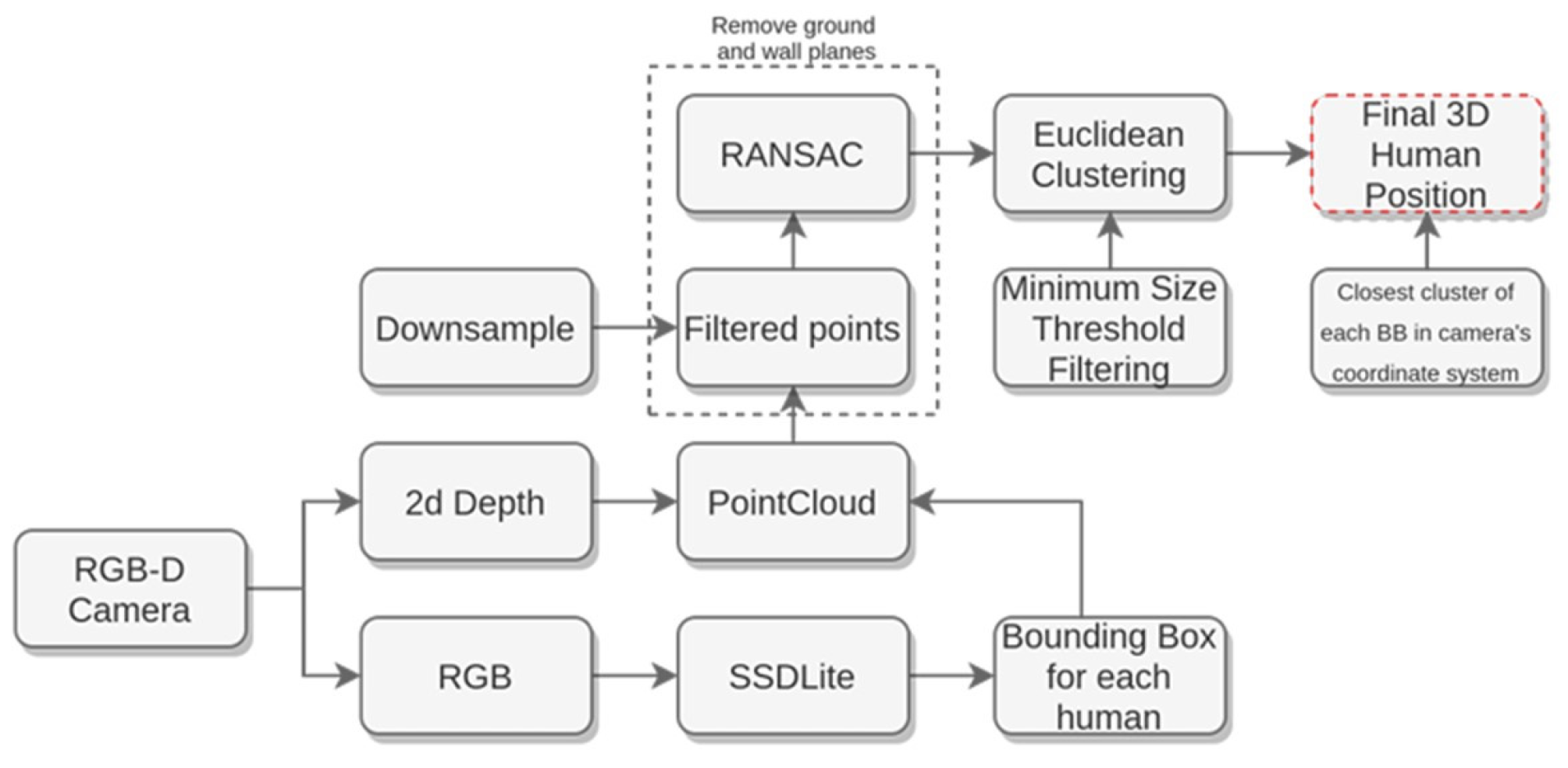
The algorithm consists of two modules: the human detection and 3D pose estimation module, shown in
Figure 3, and the human laser tracking module. In the human detection and 3D pose estimation module, the algorithm employs the SSDLite neural network [
66] to identify humans in RGB images captured by the robot’s camera. The computed bounding boxes from each image are used as pass-through filters on the produced point cloud of the depth image. Following the pass-through filtering process, a new set of enclosed points is stored in every bounding box. After clustering the human entities in these points, all the points of each person’s cluster projected on the map are averaged to obtain the estimation of their 3D position in the environment.
On the other hand, the human laser matching node clusters the laser scans to represent human legs by using geometrical features. Subsequently, the laser scan clusters are matched with the detected people by applying the global nearest neighbor method. Afterwards, the unscented Kalman filter algorithm is employed to track the detected humans through their laser scans. In this way, the sub-system is capable of tracking people beyond the camera’s field of view to the laser’s field of view that extends to 360 degrees. When tracking is achieved, the output positions of humans are fed to the costmap plugin [
67] that creates circular cost zones around them with a gradually lower cost as we move away from their centers, according to Hall’s proxemics theory [
68]. As a result, with the human-aware navigation sub-system, the robot, while navigating, is capable of redefining its path in the case of an encounter with one or more humans, thus respecting social norms.
3.3. Semantic Industrial Space Modeling Sub-System
The semantic industrial space modeling sub-system relies on a novel method that is described in detail in [
69], and it is responsible for robustly segmenting the industrial environment to assist the navigation of the robot. To perform the semantic segmentation of the industrial space, geometrical knowledge on the occupancy grid map is combined with deep learning and computer vision techniques, as shown in
Figure 4. More specifically, the sub-system relies on the fusion of data captured by the robot’s RGB-D and laser sensors during the installation process in the new environment to perform semantic space partitioning. Initially, the 2D occupancy grid map is translated into a topological representation and, through a Voronoi processing step, which conditionally partitions the edges and vertices of the diagram, a rough over-segmented spatial representation is obtained. Upon the initial over-segmentation of the environment, RGB images are combined with laser data to semantically categorize the different areas and reduce the redundant space partitions. Each of these areas, represented by a cluster of images, is fed to an autoencoder network to acquire a group of feature vectors that are then averaged to obtain one single representative vector for each area. We postulate here that using a hybrid distance metric that combines the Euclidean and cosine distances, the representative vectors that belong to the same area will be closer compared to the vectors of different areas. Using this hypothesis and an experimentally set threshold, certain areas are merged to form the final segmentation of the environment.
3.4. Object Detection Sub-System
The object detection sub-system is responsible for identifying the location and type of elevator components during the packaging stage. It relies on the collection of RGB images and the processing of these images in real time using a Transformer-based deep network. More specifically, the network architecture of the proposed object detection sub-system consists of two distinct components, as shown in
Figure 5.
The first component is a Swin Transformer [
70] that is based on a Multimanifold Multi-head Attention (MMA) [
71]. The purpose of this network is to extract hierarchical features from the image, leveraging both coarse and fine-grained information. In addition, the Swin Transformer consists of a highly attentive attention module that enables it to transform the input space into three distinct manifolds, namely Euclidean, Grassmann, and Symmetric Positive Definite, in order to more accurately model the image features. Through this attention module, the Swin Transformer is capable of paying attention to the most important features of an image, discarding irrelevant information, and improving its performance.
The second component of the proposed object detection sub-system is a standard Region of Interest (ROI) extraction mechanism that identifies candidate image regions in which objects of interest likely exist, merges regions that are too close to each other, and aligns the regions with the size of the initial image to identify their locations. Finally, the second component predicts the class of the object depicted in each region.
The output of the object detection sub-system consists of the classes and the location (in the form of bounding boxes) of the detected objects in the images, along with a confidence score that describes the certainty of the subsystem in its predictions on a scale of [0–1]. The list of recognized objects is then sent to the Q-CONPASS server and stored in the Q-CONPASS database in order to be compared against the list of ground truth objects and identify discrepancies (i.e., missing objects) before the final product is shipped to the consumers.
3.5. Ergonomic Risk Assessment Sub-System
This sub-system [
72] is responsible for estimating the risk of a worker developing work-related musculoskeletal disorders using the REBA framework. The ergonomic risk assessment sub-system, shown in
Figure 6, relies on the processing of RGB images and the extraction of 3D skeletal information using a state-of-the-art pose estimation deep network, called VIBE [
73].
The use of RGB images enables the proposed system to conduct ergonomic assessments across a wide range of work-related tasks, as cameras are not constrained by the nature of the activity. Moreover, eliminating the need for wearable sensors allows workers to carry out their duties without any physical hindrance. After the extraction of 3D skeletal information in the form of raw joint coordinates, joint-line distances that are equal to the length of the perpendicular line connecting a 3D joint to any line formed by two other joints are computed as complementary information to enhance the skeletal feature representation. The new information is then fed to a multi-stream deep network that is capable of modeling both local and global relationships among the 3D joints of different body parts and the entire body, and computing a descriptive skeletal feature representation.
To further improve the performance of the ergonomic risk assessment subsystem, distinct loss terms for the individual body parts (i.e., Reg1-Reg5) are introduced so that the predicted partial and total REBA scores are guided towards the ground truth values. The output of the ergonomic risk assessment sub-system is a set of scores that describe the risk of developing work-related musculoskeletal disorders for different body parts (i.e., neck, trunk, legs, upper and lower arms) and the entire body according to the REBA framework. These scores are aggregated and averaged per second and then sent to the DSS system via POST requests for further processing and visualization.
3.6. Decision Support Sub-System
The Decision Support Sub-system (DSS) focuses on the health and safety of the working personnel of industrial facilities through the proper processing of ergonomic risk scores. More specifically, the DSS receives as input estimated ergonomic risk scores from the ergonomic risk assessment sub-system, processes them, and outputs real-time recommendations to staff supervisors about potentially harmful movements of workers based on the REBA framework guidelines. The DSS connectivity flowchart is presented in
Figure 7 and shows that data are retrieved indirectly (i.e., through designed APIs) from the ergonomic risk assessment sub-system. A relational database is used for data persistence. The DSS has the potential to use higher-level data sources, i.e., analytical services, such as the ergonomic risk assessment sub-system, as well as lower-level sources, i.e., simple sensors, if needed.
The DSS receives input data in the form of JSON files, representing sets of ergonomic risk scores for each worker and during a specific time frame. Each set of scores corresponds to different parts of the human body and with different ranges (neck: 1–3, trunk: 1–5, legs: 1–4, upper arm: 1–6, lower arm: 1–2). The six scores, when combined, can evaluate the risk of physical strain occurring during work tasks by calculating the total score of the body (1–15, with 1 being the optimal). DSS is utilizing the total score and the relevant thresholds to support the recommendations, while score information about separate body parts can also be utilized. The maximum frequency at which the DSS can receive data is 1 sec, thus, the service is able to process data in real time.
In general, the DSS is designed to provide recommendations for optimal body posture during working hours by using sets of rules. The rules are inserted by the operator of the system and depend on the limits for safe body positions (thresholds). The user/operator is capable of setting additional threshold bands for the DSS service, e.g., regarding the frequency of a rule violation, to act like filters for the system. Rules and thresholds trigger the final recommendations. To combine the different factors of the decision-making process in a simple way, DSS allows the semantic representation of that data as nodes in a graph node editor. Ergonomic data nodes, nodes representing threshold filtering operations and time-based (windowing) operations, can be combined by the users to set up ad hoc rules.
The semantic nodes can internally encapsulate asynchronous data streams and have aggregation and correlation functionality. As a result, the operator/user can potentially adjust rules, increase rule complexity, or incorporate multiple data streams in parallel. The set-up of a visual workflow editor abstracts the lower-level changes and enhances user independence. A blank area where the users can create a graphical representation of rules using the nodes acts as the first step in representing the obtained data streams.
Internally, the designed graph is transformed into an equivalent graph of reactive programming structures (observables/operators). This feature allows the operators to adjust rules and parameters without having a technical background in IoT data stream processing. The editing interface uses open-source, client-side graph editing libraries. Basically, the DSS contains and processes the following nodes: data stream nodes (a semantic representation of data streams), aggregation/filtering/windowing nodes (that represent data stream processing functionality according to the reactive programming paradigm), and recommendation set up nodes (with which recommendations are attached to results produced by nodes of the second category). The DSS is implemented as a relational Database Management System (DBMS)-backed web application. It can be deployed locally, within the industrial facility, or hosted in the cloud. The (encapsulated) data stream processing functionality is at a lower level based on the reactive programming paradigm. Recommendations are extracted based on the frequency of high ergonomic risk movements. The higher the risk, the lower the tolerance band is set up for triggering a warning. In this way, the generated DSS recommendations are more valid as they are not based on random and sporadic measurements. Different body parts can be depicted and analyzed graphically based on the REBA score to specify which part of the body faces more strain. Average scores per worker, risk percentages, and other information are reported at any time to the supervisor. Recommendations are extracted as notifications in real time and presented on the service’s “result screen”.
4. Experimental Results
The experimental results, to validate the Q-CONPASS system, were performed under the demanding conditions of a real-life industrial environment. To this end, a scenario was designed to evaluate the functionality of the different sub-systems of the proposed system and assess whether the collected and processed visual data can lead to better production control and workers’ well-being safeguarding.
The robotic unit that was employed in the proposed Q-CONPASS system is a TurtleBot 2 equipped with various sensors and processing units, as shown in
Figure 8. More specifically, the TurtleBot 2 is equipped with a LiDAR sensor on the top of its base to autonomously navigate in an industrial environment, avoiding humans and stationary obstacles. In addition, a RealSense D435i RGB-D camera is employed to collect images from its surroundings and feed the object detection and ergonomic risk assessment sub-systems for accurate object classification and body posture estimation results, respectively. Moreover, the TurtleBot 2 is equipped with a bin for transporting various small components from warehouses to assist workers in assembling and packaging tasks. Finally, a laptop (System specifications: Intel i7-9750H 45 W/16 GB RAM/1 TB SSD/GeForce RTX 2060 6 GB GPU~100 W) is placed on the base of the robot to execute the various sub-systems of the Q-CONPASS system, while a tablet is placed on the top plate that provides an interface for users to interact with the robot and visualize the output of the Q-CONPASS sub-systems. A custom battery was developed with a capacity of 12 Ah, 14.4 V, to extend the autonomy of the robotic vehicle.
The Q-CONPASS system has been integrated into KLEEMANN’s lift cabin production line using the Business Process Management and Notation Diagram (BPMN). KLEEMANN is one of the largest lift construction companies in the European and global markets, offering all types of residential or commercial passenger and freight lifts, escalators, moving walks, accessibility and marine solutions, parking systems, and components. In the first phase, interviews with the production line supervisors were conducted to extract the business logic that is followed for the creation of elevator cabins. The initial BPMN consists of many machinery processes of raw materials (metallic plates, wood, glasses, cables) that are processed to create the cabins.
The Q-CONPASS aims to assess the production control procedures during their execution and report in real time the quality issues occurring at an early stage. The proposed BPMN of the production line, along with the way that the business logic handles each cabin order, is depicted in
Figure 9.
Special attention was paid to ensure that the proposed Q-CONPASS system is integrated into the existing production line by using only parallel processes without changing the business logic. Thus, the new BPMN diagram contains the default production process flow, and two new process flows that represent robot transportation and inspection, as well as the DSS processes.
The proposed system was developed in the framework of the Q-CONPASS project and validated in a real industrial environment (KLEEMANN’s lift cabin production line). To this end, a scenario was designed and executed to evaluate the ability of a robot to safely navigate in the environment, avoiding stationary obstacles and humans, while performing several computer vision tasks. The implemented scenario can be described with the following steps:
Step 1: The robot creates a semantic mapping of the industrial environment, allowing it to move safely between designated points.
Step 2: The robot collects and transfers consumables/materials from a warehouse (i.e., supermarket position) to the cabin assembly point.
Step 3: At the cabin assembly point, the robot inspects workers performing their tasks, assesses their ergonomic postures, and provides recommendations.
Step 4: When assembling ends, the robot moves to the supermarket to transfer missing consumables and then goes to the cabin packaging point and inspects the cabin components as they are packaged to identify missing ones.
To execute the aforementioned scenario, the Q-CONPASS system requires a process that coordinates the actions of the robot and controls their execution. Hence, a robot controller ROS node that interconnects the various subsystems and interfaces was implemented. The controller, shown in
Figure 10, acts as a State Machine and listens to commands to enable the various Q-CONPASS sub-systems. According to the developed state machine controller, a robotic vehicle can be in five possible states. The “IDLE (docked)” state demonstrates that no tasks are assigned to the robotic vehicle. The “IDLE (docked/charging)” refers to the condition in which the robot is charging, and hence, no task can be assigned to the robot. The other three states, “Cabin Assembly”, “Cabin Packaging”, and “Transfer Consumables”, are related to the corresponding business processes. It is worth noting that the “Cabin assembly” and “Cabin packaging” states concern inspection procedures during which the robotic vehicle observes the assembling of a lift cabin to assess ergonomic risk scores of the workers and the packaging of a lift cabin to identify quality control issues, respectively. On the other hand, the “Transfer Consumables” state assigns the transportation of consumables/materials from the worker to the robotic vehicle. In each system state, specific subsystems are activated to reduce computational demands. During the packaging process, the Object Detection subsystem is enabled to identify components placed on the packaging pallet. In the assembly position, the Ergonomic Risk Assessment subsystem becomes active to evaluate employees’ body posture. Significant focus was placed on developing a lightweight human recognition module for the Human-Aware Navigation subsystem. This module is designed to run entirely on the CPU, helping to reduce overall power consumption.
Initially, the scenario requires the construction of a map of the industrial environment so that the robot can safely traverse it. To this end, the ROS package gmapping is employed to produce the required map. LiDAR data are fed to the robot navigation sub-system, which is then capable of producing an occupancy grid of the industrial environment, as shown in
Figure 11. An occupancy grid splits the layout into a grid of cells with fixed resolution, and a cell can be occupied, free, or unknown depending on its value. Afterwards, minor modifications can be made in the image to remove or add obstacles. The occupancy grid can be finally saved as an image to be used by other Q-CONPASS sub-systems.
In the occupancy grid, important robot stations can be defined and annotated so that the robot can construct optimal paths between them. In this scenario, four distinct stations are defined, which are the Charging station, in which the robot can recharge its battery before running out of energy, the Super Marker station that corresponds to a warehouse, in which the robot should go to obtain consumables, the Cabin Assembly station that the robot visits to observe the assembly processes and assess the ergonomic postures of workers; and the Cabin Packaging station, in which the robot performs the quality control of the final product.
After constructing the occupancy grid, the semantic industrial space modeling sub-system is enabled to semantically segment the industrial space. This sub-system receives as input the occupancy grid and performs an initial semantic segmentation of the space, as shown in
Figure 12d. Afterwards, the semantic industrial space modeling sub-system processes input images from the different industrial areas using the RGB-D sensor and identifies whether some of these images are close to each other, leading to the merging of areas. In this case, RGB images from areas labeled as R1, R2, and R5 are shown in
Figure 12a–c, and it can be visually deduced that the images from areas R1 and R2 are much more similar to each other, compared to the image of area R5, as they depict the same area from different viewpoints. This visual comparison can be further verified using the hybrid distance of the computed area vectors, according to the method of [
69]. From
Figure 12e, it can be deduced that the hybrid distances between areas R1 and R2 and areas R2 and R3 are very small, in comparison with the distances between other areas. Given a predefined threshold of 0.17 [
69], the semantic industrial space modeling sub-system merges areas R1, R2, and R3, leading to the final semantic segmentation of the space, shown in
Figure 12f.
After the construction of the final segmented map, the human-aware navigation sub-system is employed to allow the robot to move safely along designated areas (i.e., supermarket, cabin assembly, and cabin packaging stations) and perform important tasks. The human-aware navigation sub-system is of great importance when the robot is required to move between the supermarket and the cabin assembly stations to transport small cabin components within its bin storage. In this case, the human-aware navigation sub-system enables the robot to fulfill its task while taking into consideration the safety of employees. The human-aware navigation sub-system enables the robot to follow lanes and promptly recognize humans and other moving obstacles within its field of view and create paths to keep a safe distance from them in real time, as shown in
Figure 13. During all experiments, the robotic vehicle was capable of avoiding collisions with humans, moving obstacles, and even with other moving vehicles within the facility that would have occurred without the proposed human-aware navigation sub-system. In addition, throughout the experiments, the robot was able to find a feasible path to reach all the defined goals, without obstructing the work of employees.
The next step of the implemented scenario involves the robot moving to the Cabin Assembly station to observe the employees during their work and assess their ergonomic postures to identify risks of musculoskeletal disorders. In this step, the ergonomic risk assessment sub-system is employed to analyze video sequences and extract skeleton poses that are then used to compute REBA ergonomic risk scores.
Figure 14 presents snapshots of the robot capturing the posture of a worker during the assembling of a cabin and assessing his REBA ergonomic risk score for individual body parts and the entire body. In addition,
Figure 15 depicts the temporal evolution of the REBA scores for individual body parts and the entire body as a worker performs a cabin assembling task. From this figure and the corresponding image snapshots, it can be seen that the proposed ergonomic risk assessment subsystem can accurately identify the strain in the different body parts. Specifically, when the worker stretches his arms, the ergonomic risk score for the upper arms exceeds the value of 3. In the same fashion, when the worker sits on the floor with his legs folded, the ergonomic risk score for the legs rises to a value of over 3.5, indicating increased strain in those areas. From an ergonomic perspective, the worker’s posture in the first two snapshots is suboptimal, resulting in a high-risk score for the entire body of over 9. As the worker gets up, the ergonomic risk associated with the arms and legs decreases, and the risk for the entire body drops to a value of under 7.5, indicating a medium risk to their posture. The computed REBA risk scores are then sent to the Decision Support sub-system, which informs the employee supervisor of potential risks.
An important function of the DSS is its ability to extract reports in Excel sheets, a graphical representation of the incoming data, and vivid visualization of the ergonomics monitoring, according to the needs of KLEEMANN. More specifically, the generated reports present the average and maximum REBA risk scores for each worker and the calculated risks for developing musculoskeletal disorders. It is worth noting that the score values in the report files are reversed to represent an evaluation where higher values indicate better body posture (
Figure 16). These reports can significantly assist the production line supervisor in implementing changes in the shift schedule towards improving the well-being of the employees and reducing the risk of developing musculoskeletal disorders. In addition, through the graphical representation of the ergonomic risk scores (
Figure 16), the production line supervisor can oversee the ergonomic risk and duration of the workers’ posture and take necessary precautionary measures for their health and well-being.
In general, the experiments revealed that the workers quite often perform their tasks in awkward body postures; thus, changes in the form of alternative body part movements and angles can be recommended by the system or breaks added to the shifts to reduce the risk of developing musculoskeletal disorders. Furthermore, with daily recommendations from the supervisor, the employees began to adjust and improve their body posture throughout working hours and improve their overall health.
It is worth noting that employees in the cabin assembly manufacturing cell can request consumables (e.g., bolts, nuts) at any time. The Q-CONPASS system processes these requests, instructing the supermarket employee to collect the necessary items and issue a command for the robot to retrieve them. Moreover, the GUI is accessible through the local network for all users who have the necessary credentials. With the developed GUI, employees can request the necessary consumables using their smartphones. To demonstrate this functionality, the implemented scenario included the robot traveling to the supermarket to pick up the requested consumables. Thus, the robot had to move from the cabin packaging position to the supermarket.
Figure 17a presents the path that was generated by using the assigned corridors.
Figure 17b presents the robot’s response when humans are detected and readjusts its path in order to avoid them.
Figure 17c shows the robot’s velocity while it is located inside the supermarket area, which is characterized as a dangerous zone. Dangerous zones are the areas with increased human or vehicle presence, and thus, the maximum allowed speed is even lower. When the robot exits the danger zone, its velocity increases to 0.35 m/s until to reaches its destination. The same chart highlights that the minimum human-robot distance throughout the navigation procedure was 3.6 m.
Finally, the robot goes to the Cabin packaging position after a request from the end user to monitor the packaging procedure and the object detection subsystem of the Q-CONPASS system is employed to verify that all important cabin components have been successfully packaged and identify missing ones to inform the person in charge. The proposed object detection sub-system is capable of recognizing cabin components in real time, while they are loaded into the packaging pallet, and informs the Q-CONPASS server of the objects that were detected. The end users can be notified about the missing components through the table located on top of the robot. Moreover, the GUI is accessible through the local network for all users who have the necessary credentials. With the developed GUI, employees can manually inspect the packaging of an order and use the Q-CONPASS system to confirm that all required components are included on the packaging pallet, even if the robot is not currently inspecting that specific order. This functionality enables verification of the packaging process while removing the need for printed BOM lists.
Table 1 presents the performance of the proposed object detection sub-system in comparison with other object detection approaches in a dataset developed to evaluate the Q-CONPASS system, consisting of almost 11k elevator parts, while
Figure 18 visualizes two detections of the object detection sub-system that shows the type of the detected object, along with the confidence of the sub-system on its detection.
Table 1 shows that the proposed object detection sub-system can achieve really high accuracy, overcoming other object detection approaches. From
Figure 18a,b, it can be deduced that the proposed object detection sub-system can accurately identify the correct class of the cabin component with high confidence, thus automatically and reliably overseeing that all components are in the product package. Afterwards, the Production line supervisor can see through the developed web interfaces of the Q-CONPASS system, which components of the cabin have been correctly loaded into the packaging pallet, and confirm when the packaging is completed.
Table 2 outlines the CPU and GPU utilization across various subsystems of the robot during different operational states. The Semantic Mapping Subsystem is executed only during the mapping phase, with a CPU usage of 28%. The Human-Aware Navigation Subsystem, which runs continuously during robot movement, consumes 11% of CPU power (approximately 8 watts). In this phase, the robot also consumes approximately 15 watts for its movement (motors and lidar). The Lane Follower Subsystem is triggered when the robot has difficulty localizing itself, using 23% of CPU and 38% of GPU capacity, amounting to around 40 watts. The Object Detection Subsystem activates during the “Cabin Packaging” state, fully utilizing the GPU, drawing about 120 watts. Finally, the Body Risk Assessment Subsystem is enabled in the “Cabin Assembly” state, utilizing the GPU at 99% for 1 min to process a 5-min video and generate REBA scores, resulting in an estimated energy consumption of 5 watt-hours per video. The results indicate that the “Cabin Packaging” and “Cabin Assembly” states consume a substantial amount of energy, and prolonged operation in these states can significantly reduce the robot’s autonomy.
Figure 19 visualizes the developed web interface of the Q-CONPASS system, which shows the production line supervisor, which cabin components have been recognized and loaded into the packaging pallet, thus contributing to the quality control of the final product. Also, shows the option of the developed GUI to call the AGV by pressing the button “Call the AGV for Packaging Monitoring”. In addition, the production supervisor has a tool at his disposal to confirm that the packing procedure was carried out in accordance with the plan, lowering the likelihood of a shortage in the packaged order. Moreover, a video file is recorded as evidence to document any issues that may arise during the delivery of the order to the customer.


 ,
, 


