1. Introduction
Based on the IoT analytics market survey issued in September 2021 [
1], one of the major factors driving the growth of the IoT analytics industry is the increasing number of connected devices. By 2025, according to the recent IoT analytics 2021 report, 27 billion IoT devices are expected to be connected to mobile networks; therefore, the amount of data, network traffic, devices capabilities, and the number of use cases are exponentially growing and resulting in complex solutions, trying to deal with a vast number of devices with an unpredicted number of connected things. The newly designed IoT landscape introduces a new issue regarding processing the increasing volumes of data. Initially, the overhead time required to process the data generated on the edge device to the central server may cause a delay. Thus, transmitting extensive volume data over the network and devices may cause the bandwidth to be throttled. This process may result in unaccepted latency, which would have a negative impact on the industry. Thus, distributed computational models, such as edge computing, are introduced to reposition the whole process from data storage to computation in a decentralized data center (private clouds), which brings data storage to computation closer to the IoT devices which generate the data at the edge of the network in nearby locations to avoid the resultant latency. Introducing the next generation of IoT applications, osmotic computing, a new emerging dynamic distributed computational model is proposed to solve the cost, latency, heterogeneity, and complexity of IoT applications.
Highlighting the key problem, given such a scalable application environment, is the absence of predefined infrastructure configurations (e.g., cloud instances, edge instances, gateways, and load balancers) required to achieve the target quality of service (QoS) parameters (e.g., throughput, latency, and scalability) for the IoT application performance. The osmotic computing model provides a dynamic runtime federation/management principle for the infrastructure components, enabling ecosystem resource governance from a vertical perspective across cloud, fog, and edge layers to satisfy all the IoT application targets. In detail, although all architectural concepts are presented, it is difficult to determine the management policies of how the resources will be orchestrated and deployed according to the unpredicted runtime performance loads, considering each resource’s capabilities and limitations to maintain the application performance within the accepted QoS parameters.
The main objective of this scientific research is to demonstrate the advances of dynamic orchestration provided by osmotic computing architecture, introducing osmotic message-oriented middleware, allowing the application of automatic deployment and reconfiguration concepts to smart IoT applications at runtime to utilize all the available resources. The osmotic middleware manages the application resources based on provisioning runtime data provided by the resources themselves fed into the MAPE-K model, enabling the dynamic adoption against the unpredicted variables where edge resources are limited in terms of computational and network capacities. The proposed middleware is considered a dynamic orchestration platform able to manage various IoT applications with the ability to share physical/virtual resources, maintaining the performance QoS requirements, federating heterogeneous resources across different layers, and offering the benefits of a scalable, elastic, and adaptable end-to-end IoT osmotic solution. The proposed model is evaluated using benchmarking of the performance indicators in both real and simulated environments. The paper aims to validate the impact of the proposed architecture on the application performance and QoS requirements at both infrastructure and application levels.
The rest of this research is organized as follows:
Section 2 provides background and related work. Then, a design architecture of the proposed solution is presented in
Section 3.
Section 4 discusses the implementation methodologies.
Section 5 demonstrates the experiments and the results obtained from their validation. Finally,
Section 6 concludes this article and presents a roadmap for future research guidelines.
2. Background and Related Work
Microservices are an architectural design for building a distributed computing application. Microservice architecture is a recently introduced software development methodology in which complex software is sliced to independent components or services that could require communication through well-defined contracts over standard protocols called APIs. Microservices should be loosely coupled, and each should be responsible for a single functionality. Additionally, a microservice architecture deals with services individually as isolated components, which means that a single service could be underperforming. In this case, the underperforming service could be terminated and replaced by a high-performance one. Containerization is a recent trend in software development as a competitor to the virtualization method for hosting distributed applications without the need for a guest operating system for each virtual machine. Each application is hosted on a separate container, achieving singularity as a best practice. The containers can communicate with each other using message-oriented protocols. A cloud-native application design is considered a collection of small, independent, loosely coupled components, including the API gateway, container registry, microservices message-oriented middleware. This new distributed computing software system design provides the tools to achieve elasticity, scalable, and required QoS.
To define the current state of the art, the following topics are studied, covering previous research areas used as guidelines of work for this article: virtualized microservice architectures, cloud/edge/fog Computing from the IoT perspective, and osmotic computing.
2.1. Virtualized Microservice Architecture
In recent times, microservices have become a global trend. Microservices offer several advantages, such as better scalability, flexibility, agility, and more. The shift from a monolithic architecture to microservices (Google, Amazon, and Netflix microservice architectures) was implemented by multiple tech leaders. A comparison between monolithic and microservice architectures is demonstrated in
Figure 1. Monolithic applications can be hard to maintain, especially when poorly designed. Monolithic systems have tightly coupled processes; therefore, even a small change can cause several issues related to the codebase. A single change can result in an entire program not functioning. At the same time, microservice architecture changes the application design by splitting the codebase into small partitions. Each partition should be loosely coupled and independently operational, known as a microservice. A microservice should have its database and file system storage, which should not be accessible by other microservices. Different microservices may be implemented using one or more programming language(s) and database types (e.g., relational, document, graph, or time-series database).
Software virtualization allows the creation of different virtual resource versions (e.g., virtual-based computer resources or software-based resources). These virtual computer resources can consist of computing nodes, disk storage, networks, and operational servers, in addition to applications (see
Figure 2a). Virtualization works by using hypervisors [
2] installed on the operating system, taking the physical resources shared between multiple virtual environments. Virtualization techniques are inapplicable for both cloud, fog, and edge computing environments, due to their resource-limited capabilities.
However, containerization is a unikernel/lightweight replacement to virtualization [
3]. This allows a software application to be encapsulated in a container, including its operational environment. Each container consists of a running package of software that is executed on top of a host operating system, offering a lighter solution applicable for a resource with limited capabilities (e.g., Raspberry Pi and Arduino single-board devices). A host can support multiple concurrent containers.
In a containerized microservice architecture, each microservice defines its characteristics of precise scaling [
4], resources capabilities, and its lifecycle ownership; these characteristics should be orchestrated and maintained using a virtual container individually, which quickly becomes a complex and challenging effort to be managed manually, or by using manual automation tools, such as Docker Compose [
5]. Thus, one of the container orchestration tools can be used to federate the automation of software deployment, scaling, and management (e.g., Kubernetes [
6], OpenShift [
7], Apache Mesos [
8] or Helios [
9]). Alam in [
10] and Hegyi [
11] discussed the benefits of integrating IoT and microservice architecture based on Docker Swarm as a lightweight virtualization deployment processes tool.
2.2. Cloud, Fog, and Edge Computing from IoT Perspective
Edge, fog, and cloud computing infrastructures allow organizations to benefit from various data storage assets and computational resources. Even though there are similarities between the three infrastructures, these computing resources are represented as different IT layers; each one extends the capabilities of the previous layer. Most organizations are familiar with cloud computing since it is now a de facto standard in many businesses. Cloud computing hosts data and software programs over the internet instead of using local disk drivers. Cloud computing offers organizations an extended reach to unlimited cloud resources as an alternative to the prime host servers’ resources. Fog computing provides increasing cloud computing to the edge of an enterprise’s local network, which reduces latency. It promotes intelligence down to the local area network (LAN), manipulating data in a fog node. It involves relocating computational power closer to the IoT sensors connected to the system. Edge computing can be considered the processing of sensor data away from the centralized nodes and close to the logical edge of the network. It effectively pushes the computational resources to the edge of the network.
One definition of the edge and fog architecture is the runtime discovery of the computing nodes (e.g., edge or fog nodes), where scalability is configured dynamically when required. Ref. [
12] introduced an architecture to connect IoT, edge, and cloud resources. Ref. [
13] focused on utilizing the edge and fog nodes by enabling the discovery methods on the nodes themselves. Extending the discovery methods to include the cloud resources is a different novel method from the usual edge and fog nodes residing in a private network; this was discussed in [
14], providing an approach to construct resource-sharing contracts at the runtime with the cloud providers. Another direction is to eliminate the cloud infrastructure from the ecosystem by increasing the capabilities of the edge and fog nodes, considering the heterogeneous types of applications and required computation. Introducing a distributed orchestration framework, which is only limited to edge and fog nodes, was demonstrated by [
15,
16,
17]. A new model was discussed by [
18,
19,
20,
21], where nodes are replicated in response to high loads across the edge, fog, and cloud layers. This model often fails in utilizing the resources, as there is no option to remove a node from the topology, which means that once a node is replicated, and load is back to normal, the node will no longer be required but still exists on the topology, which impacts the model economics and resources utilization.
A relation between big data and IoT cyber–physical systems (CPS) was discussed in [
22], providing a survey, stating that power consumption is still an existing problem and lacks the dynamicity of the orchestration. Ref. [
23] introduced AI (artificial intelligence) enabled networks to overcome random access and spectrum sharing depending on the model-free method to reach good system performance without relying on accurately labeled data. IoT-based smart grids addressing high bandwidth with low latency proposing an architecture using edge computing without extending the capability to either fog or cloud spectrums was discussed in [
24]. Ref. [
25] provided a distributed clustering algorithm in IoT environments based on agents to manage IoT resources, where each agent represents a single smart device.
2.3. Osmotic Computing
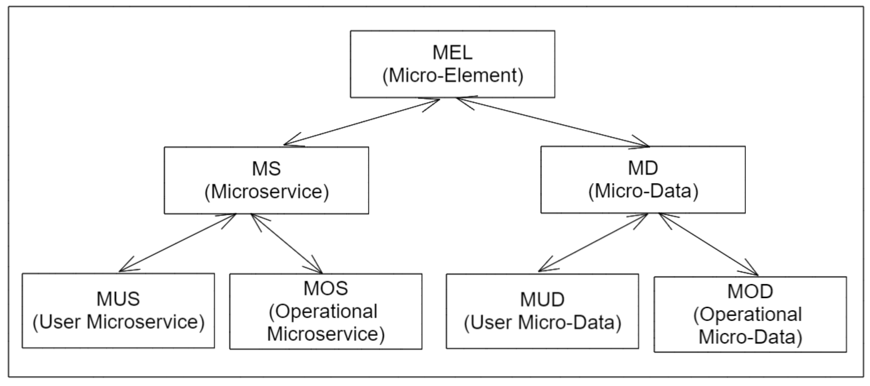
Osmotic computing introduces the concept of a membrane, which represents a virtual layer based on the infrastructure (e.g., cloud, fog, or edge resources). The micro-element is the basic functionality, or data encapsulation acts as the osmotic solvent which could migrate within their different membranes, without having any external interaction with the outside world. A micro-element can be categorized by a hierarchical representation shown in
Figure 3: (1) A microservice represents the encapsulated functionality unit; (2) micro-data represent information in different data structural formats.
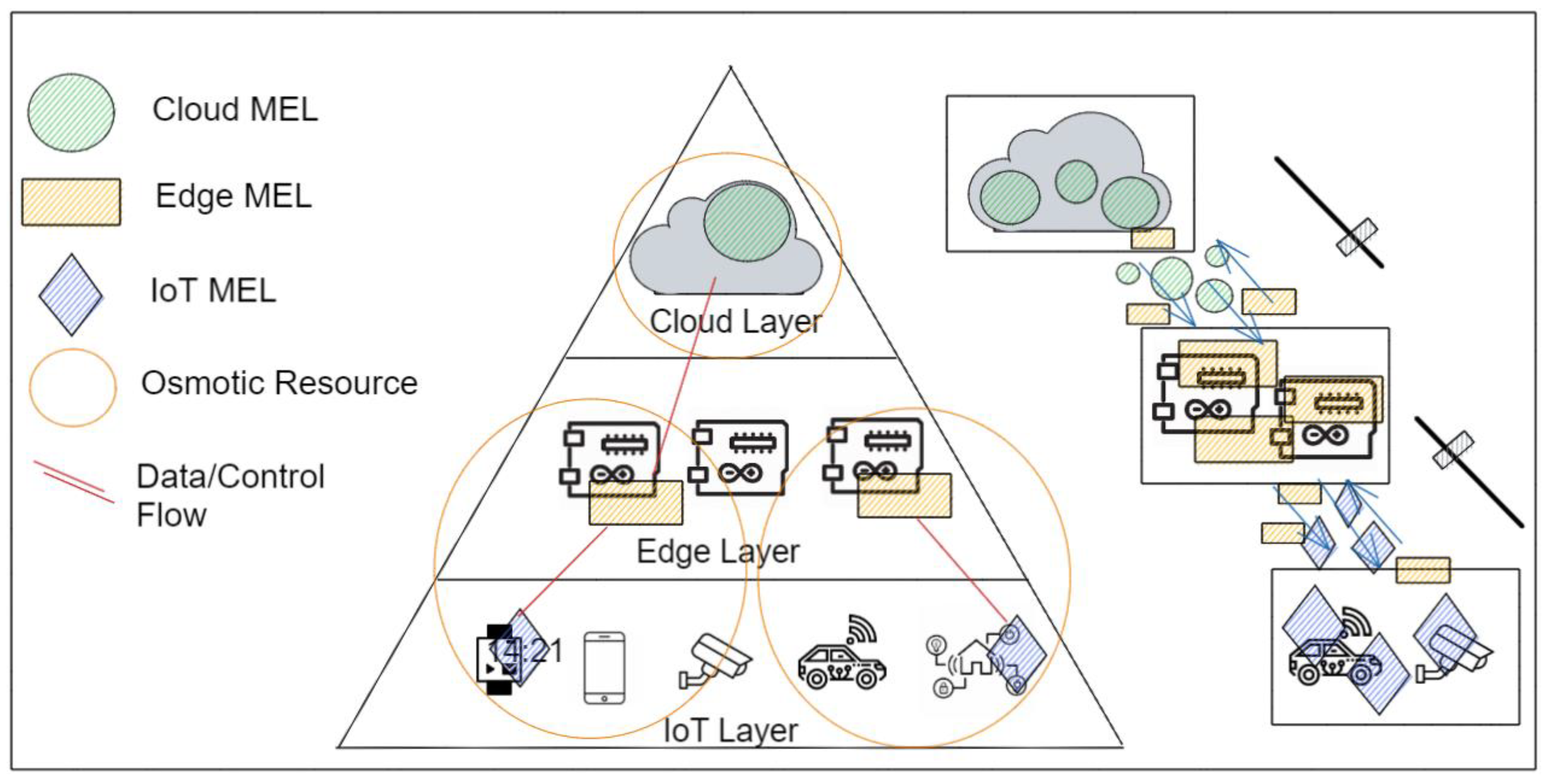
The resources federation considering different cloud, edge, and IoT systems is the main issue for osmotic computing, as shown in
Figure 4. Web services orchestration in cloud computing based on service-reputation-based selection trying to solve the rising number of requests was discussed in [
26,
27,
28]; edge/fog-based orchestration for IoT was reviewed in [
29,
30,
31]; moreover, IoT [
32] considers the continuum between orchestrating linked entities, both small and large. Cloud-computing-based service orchestration was discussed in several articles, including [
33,
34,
35,
36], where an architectural design for the adaptive management of end-to-end connected devices in a cloud infrastructure from SDN (software defined networking) technology perspective was investigated.
Moreover, a video analytics application was coordinated end to end using cloud, and edge computing deployed on optical networks was implemented in [
37], validating the feasibility of using SDNs over optical networks. A middleware was presented in [
38], discussing a minified framework and new computational models for cloud and grid resource orchestration targeted to assist researchers and analysts at the big-scale extensive development of unified computing frameworks. Multitask applications utilizing dynamic resource orchestration in varied mobile cloud computing, which realizes a processing resource provision for varied computing infrastructures, was conducted as a multi-purpose optimization problem depending on different metrics [
39]. A distributed virtual machines (VMs) cloud computing orchestration framework that provides a self-adaptive framework to create VMs migrations to select hosts to be running or stopped, when necessary, was implemented in [
40]. Additionally, polyphony was presented in [
41]; polyphony is a robust, scalable, and flexible framework that efficiently controls a large set of computing resources to perform parallel computations which can employ resources on the cloud and additional capacity on local machines, as well as saving resources on the supercomputing center. Ref. [
42] presented the concept of orchestration as a service engine depending on a temporal reconfiguration method that attempts to partition the cloud server resources between BPEL operations, using a temporal segmentation algorithm. A service-level agreement (SLA) based orchestration (service level agreement) approach for cloud computing services, which aims at maximum performance, was presented in [
43]. In [
44], the problem of confidentiality control in the cloud via SLAs and a policy orchestration service ensure that service providers apply valid proposals through proper monitoring. The review of container-based deployments in the cloud, considering the automated deployment challenges in helping IT staff handle large-scale cloud data centers, was provided in [
45]. The SINC project focuses on creating and managing end-to-end slices of different resources from different, distributed infrastructures [
46] over the entire IoT network. Ref. [
47] presented a classification of the recent distributing schemes that have been introduced for IoT, fog, cloud.
3. System Design
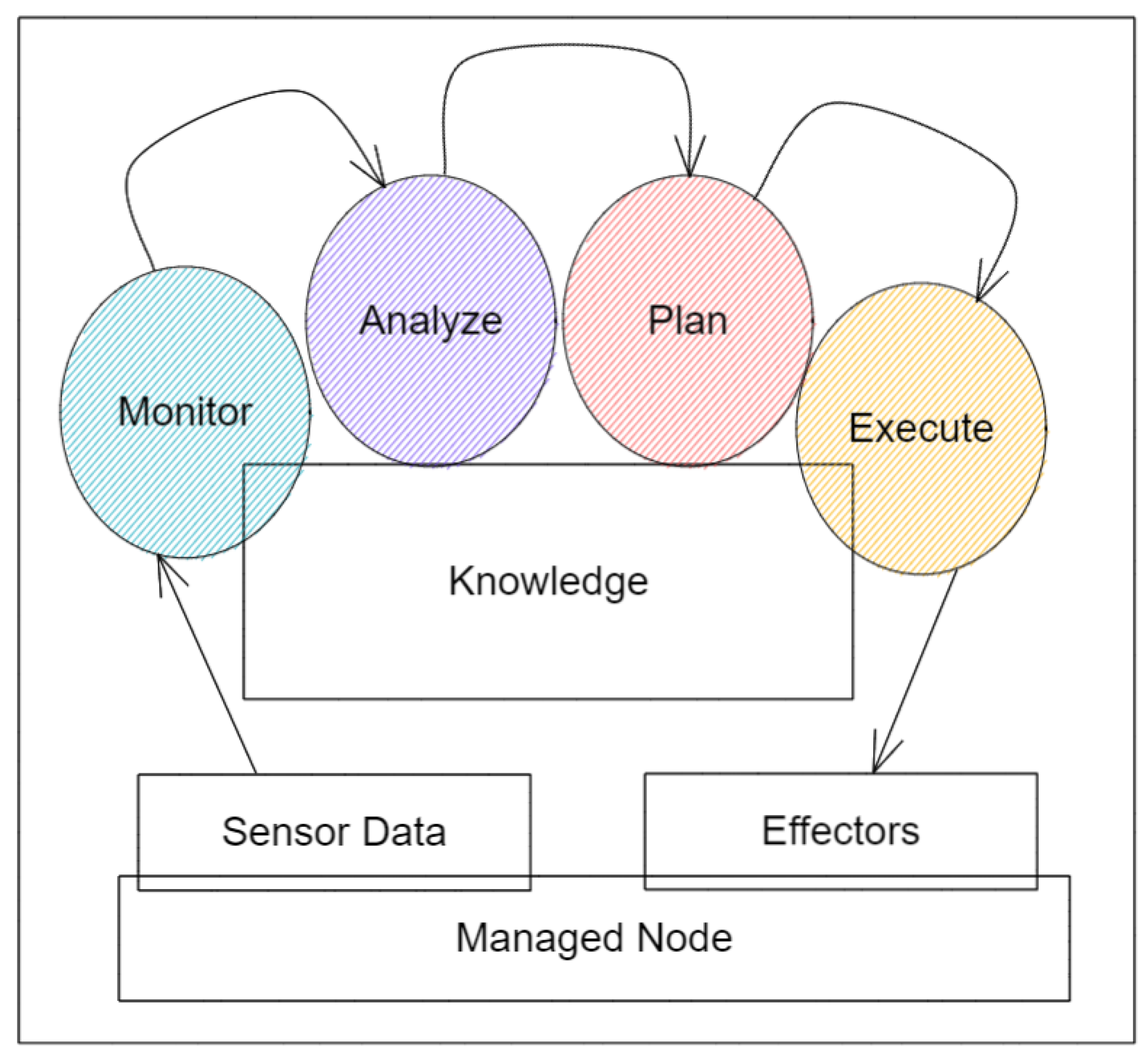
In this paper, we designed an osmotic computing middleware that enables dynamic resource orchestration, offering an osmotic platform to discover the definition and deployment required to maintain a scalable, elastic, and adaptable end-to-end IoT osmotic solution. The presented osmotic computing middleware architecture is based on the MAPE-K reference control model (see
Figure 5), following four principal actions, (1) monitor, (2) analyze, (3) plan, and (4) execute using a central shared knowledge, applied in various self-adaptive computational [
48]. The proposed architecture, divided into multiple phases, is a MAPE-K continuous feedback-driven engine based on resource-continuous provisioning to develop self-adaptive software systems. The main actors of the model are described as follows.
Monitor is responsible for the data gathering, which is input for the entire model.
Analyzer is responsible for discovering data analytics and insights based on the indications provided by the monitor process and stored knowledge data.
Planner structures the actions needed to achieve the target system requirements according to the supported adaptation mechanisms, including creating or selecting action plans to implement the managed resources’ required modifications (e.g., MELs).
Executor changes the managed resource’s behavior based on the planner’s actions through defined connections to the resources’ layers.
All four of the main actors share a knowledge base that stores data, which consists of historical data logs.
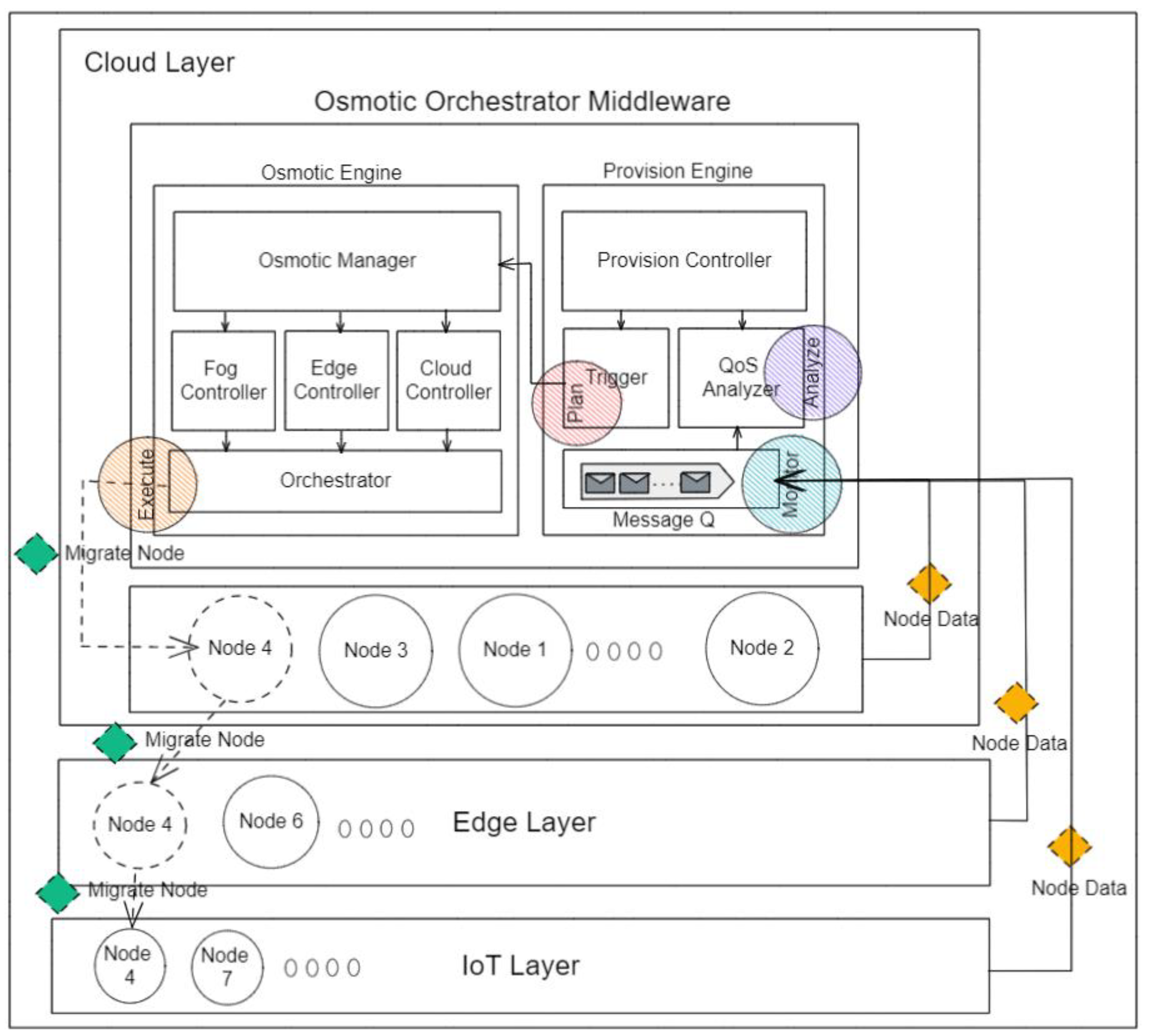
Following this behavior, in the proposed architecture (see
Figure 6), MELs are represented as lightweight containerized microservices running on managed resources deployed across cloud, fog, and edge computing nodes. In a transient IoT device scenario from one physical location to another (e.g., moving vehicle), the current running MEL on the edge node is stopped, and a new instance is deployed on a nearby edge node.
The managed node structure (as shown in
Figure 7) is a virtual containerized node; its base layer is the container engine, which is the primary channel for virtualization and hosts the container image containing the required libraries and configurations for the MEL. A single managed node can host multiple MELs belonging to one or many applications as isolated virtual services, keeping data and services completely protected unless the MEL configuration explicitly opens partial slices for sharing based on the MEL logic. The provisioning agent is responsible for sending analytics, including the node and MEL’s infrastructure and application performance matrices, to the provisioning engine for enabling self-adoptable IoT applications.
The provisioning engine consists of a message queue, which receives all the nodes’ data of the MAPE-K monitor, which is consumed by the QoS analyzer, which represents the MAPE-K analyzer, to perform continuous runtime provision to both the running nodes and MELs; whenever a change request is required, the analyzer instantly reports to the provisioning trigger, which acts as the MAPE-K planner, plans the action, and breaks it down into optimized deployment micro-actions to be sent to the orchestration engine to handle across the cloud, fog, and IoT layers. The optimized actions produced by the provisioning engine contain the information needed for the deployment to create a new node or terminate an existing node. In the case of creating or migrating a new node, the actions include metadata to describe the node characteristics (1) type (2) configuration (e.g., CPU, memory, and storage), (3) target layer (e.g., cloud, fog, or edge), and (4) availability zone (e.g., Data-Center-1, Data-Center-2, or U.S. East (Ohio)).
The osmotic engine is called by provisioning the engine trigger passing required action. Then, the osmotic manager uses the node configuration to pull the corresponding MEL resource and set the required hardware characteristics to add both provisioning and osmotic agents. Then the node configuration is sent to the other cloud, fog, or edge controllers responsible for translating the configurations into create, terminate, and migrate commands for the orchestrator to execute directly to the cloud, fog, or/and edge layers. Required actions may include micro-actions targeting one or more nodes on different layers.
In this architecture, the network topology of the nodes is not predefined and is subjective to be changed according to the runtime constraints to manage the system QoS requirements. Thus, the problem of dynamic scheduling is translated to a resource assignment problem to utilize the resource provisioning data to figure out an optimal assigning solution. For this purpose, we use the optimized dynamic Hungarian algorithm [
49] to answer the MELs scheduling issue in the complexity of
O(
n2) (see Equation (1)) because it is valid to optimally solve the assignment in conditions with changing edge costs or weights.
Optimized dynamic Hungarian algorithm.
In depth, the MELs topology is represented by a bigraph in which vertices can be divided into two disjoint and independent sets, V and U, and E, a set of weighted edges between the two sets; the problem is defining which subset of the edges have a maximum sum of weights, given that each node vi ∈ V or ui ∈ U has at most one edge eii ∈ E. The problem may be considered a minimization problem by converting edge weights wij to a set of non-negative edge costs, cij = W − wij, where W is at least as large as the maximum of all the edge weights. The algorithm generates dual variables αi to each node vi and dual variables βj to each node vj. It utilizes the fact that the dual of the minimization version of the assignment issue is feasible when αi + βj ≤ cij. The Hungarian algorithm maintains reasonable values for all the αi and βj variables from initialization through termination. An edge in the bipartite graph is called admissible when αi + βj = cij. If the affected node is unmatched, then the cardinality of the matching is decreased by one while in the initialization phase. If an increasing route is discovered, the current set of matches increases by reversing the matched and unmatched edges along this route. Because there is one more unmatched edge than matched edges, this reversing increases the number of the matching elements by one, completing a single round of the algorithm. If an increasing route is not found, additional edges are included by changing the dual variables to bring them into the equality subgraph, making them acceptable, and the search continues.
The MELs assignment represents the core osmotic orchestration logic, depending on the data generated from each node and each running MEL. Both application and node performance analytics are combined to determine the edge wight to optimize the topology of the osmotic topology. The algorithm execution yields the selected node to deploy, migrate, or terminate a MEL called a change request. Then, the osmotic engine handles the change request by determining the required prerequisites, including the MEL image, manifests, and configurations for the layer controllers to execute through the orchestrator. Once a MEL is deployed, its provisioning data are pushed to the provisioning engine queue by the node provisioning agent on a periodical timeframe to complete the MAPE-K feedback loop, evaluating the new topology performance.
4. Implementation
The osmotic middleware is designed as decoupled interacting components fulfilling the SOLID design principles to create more maintainable, understandable, and flexible software. The proposed middleware architecture (see
Figure 6) is implemented to be hosted on either public or private clouds (see
Figure 8). The interaction between the osmotic middleware components (e.g., provisioning engine and osmotic engine) is accomplished through either direct reference or HTTP methods communication (e.g., Get, Post, Put, and Delete), inheriting a message-oriented architecture, which assures system-to-system communication aiming for a zero-failure solution.
The osmotic orchestrator middleware uses Java Boot Spring as interacting microservices representing different system components. The Boot Spring framework uses Tomcat as an embedded server for self-hosted microservice implementation. HTTP RESTful API requests are used for internal service-to-service communication; data objects are translated into the JavaScript Object Notation (JSON) standard interchange data format.
The osmotic manager is the main executor component, where the provisioning change request sent by the trigger is translated from JSON instructions into deployment request(s). The deployment request of the MEL containers is initiated by accessing the MySQL database through the resource manager to obtain the prerequisites list from preparing the requested MEL container; the list consists of the keys for the MEL image identifier, a set of configurations for target node data, and required manifests. The MEL image identifier, which contains the image name, is used to pull the required image from the private docker images registry, which is responsible for storing all different MELs images into the solution. The configuration list is used to access the configuration file repository for node accessing parameters and required tokens. Manifests are stored in a separated file repository containing Docker Compose YAML scripts, which define the container services, networks, and volumes. Then, deployment requests are sent to the corresponding cloud, fog, and/or edge controllers to be deployed via a Kubernetes Cluster.
The assigned controller translates deployment requests to a set of deployment commands sent to the Kubernetes Cluster for execution on the targeted node. The communication between the controller and Kubernetes Cluster is accomplished using the exposed Kubernetes exposed APIs implementing kubectl CLI (command–line interface). The deployment request is translated to a set of deployment commands sent to the Kubernetes Cluster as HTTP asynchronous API requests. Whenever a callback is received, the response is processed, and the topology is updated then stored in the MySQL database. Additionally, the new topology is sent to the provisioning engine for enhanced accurate monitoring.
Managed nodes are virtual containers running on the docker engine facilitating hosting on a different cloud, fog, and edge layers. The docker engine enables the running of containerized applications, including MELs as a microservice self-managed application and node agents (e.g., osmotic and provisioning agents), providing all hardware capabilities (e.g., CPU, memory, storage, and connectivity) which is required for running the containerized applications. Docker defines an abstraction for machine-specific settings that support different operating systems (e.g., Windows, Ubuntu, Debian, CentOS, and Raspbian). This abstraction allows a wide range of devices with different hardware specifications to be supported (e.g., Arduino, Raspberry Pi, x86_64, and amd64).
Node agents support the osmotic middleware functions on the managed node deployed side. Osmotic agents manage the running containers, either adding a new container or stopping/removing a running one acting as an interface between the osmotic middleware and node’s installed docker engine. The osmotic agent is implemented as an open-source Python command executer with an open communication channel with the osmotic orchestrator. The provisioning agent is responsible for sending the managed node, running containers, and applications’ performance matrices to the provisioning message queue, allowing non-blocking communication to the provisioning engine.
The provisioning engine receives the pushed messages sent by the provisioning agents through the message queue, which is implemented as MQ Telemetry Transport (MQTT), which is designed as an enormously lightweight publish/subscribe messaging transport that is ideal for connecting remote devices with a small code footprint and minimal network bandwidth. The QoS analyzer is subscribed to the MQTT queue, listening to all incoming messages. Once a message is received, it is stored in InfluxDB, an open-source time-series database (TSDB) built to handle large volumes and multiple sources of time-stamped data produced by applications, sensors, and resources. The data stored in InfluxDB have time-series data related explicitly to managed nodes, containerized applications (MELs), and performance indicators. Then the QoS analyzer evaluates the whole solution topology. Whenever a load is detected, the most recent network topology is pulled from the osmotic engine, followed by a change request creation, which contains a specific redeployment/reconfiguration plan, and sent to the trigger controller, which is responsible for running the implementation optimized dynamic Hungarian algorithm to obtain the optimal node to host any new required MELs. The change request may include steps targeting multiple nodes and MELs.
5. Validation of the Solution
For the osmotic middleware architecture validation, a microservice-based vehicle monitor application is implemented with a simple workflow that enables real-time vehicle monitoring assistance. The application is divided into three MELs: (1) monitor—constantly sends its GPS location and speed; (2) update—checks for car software updates; and (3) break—sends an update whenever car speed is decelerating. All three MELs update a car status with speed and location; this application is considered a minimum valuable prototype only used for osmotic middleware testing.
Vehicle monitor MELs are implemented with Net Core 5.0. Kubernetes APIs are used for service discovery in the vehicle monitor application, which queries the API server for Endpoints, that receive an applicable updated list whenever the set of managed nodes in the layer (cluster) changes. The vehicle’s data are simulated using JMeter and with periodic requests. A test plan is configured with 1000 threads (simulating 1000 vehicles), for a duration of 10 min (600 s). Waiting time is implemented to confirm that the system processes the load, keeps its performance active, and does not fail. There is an interarrival distributed time gap between API calls. A timer randomization function manages it with Gaussian configuration with a variation of 500 ms and a fixed delay offset of 1000 ms.
Table 1 shows the specifications of the infrastructure used to set up the test environment. Both fog and cloud nodes are EC2 instances hosted on Amazon Web Services (AWS, Seattle, WA, USA). Moreover, the osmotic middleware is a t2.2xlarge EC2 instance hosted on AWS. Edge nodes are Raspberry Pi 4 model B with Broadcom BCM2711, 4 GB LPDDR4, Quad core Cortex-A72 (ARM v8) 64-bit SoC @ 1.5 GHz, and 5.0 GHz IEEE 802.11ac wireless. Edge nodes and IoT devices are set up at the same laboratory connected to a Wi-Fi router with 20 Mbps. For the IoT devices, a simple mobile application is implemented and installed on an iPhone 12 Pro Max device connected to the same Edge Wi-Fi router.
5.1. Experiment 1—Latency Measurements
Regarding the latency measurements, using our test environment infrastructure in
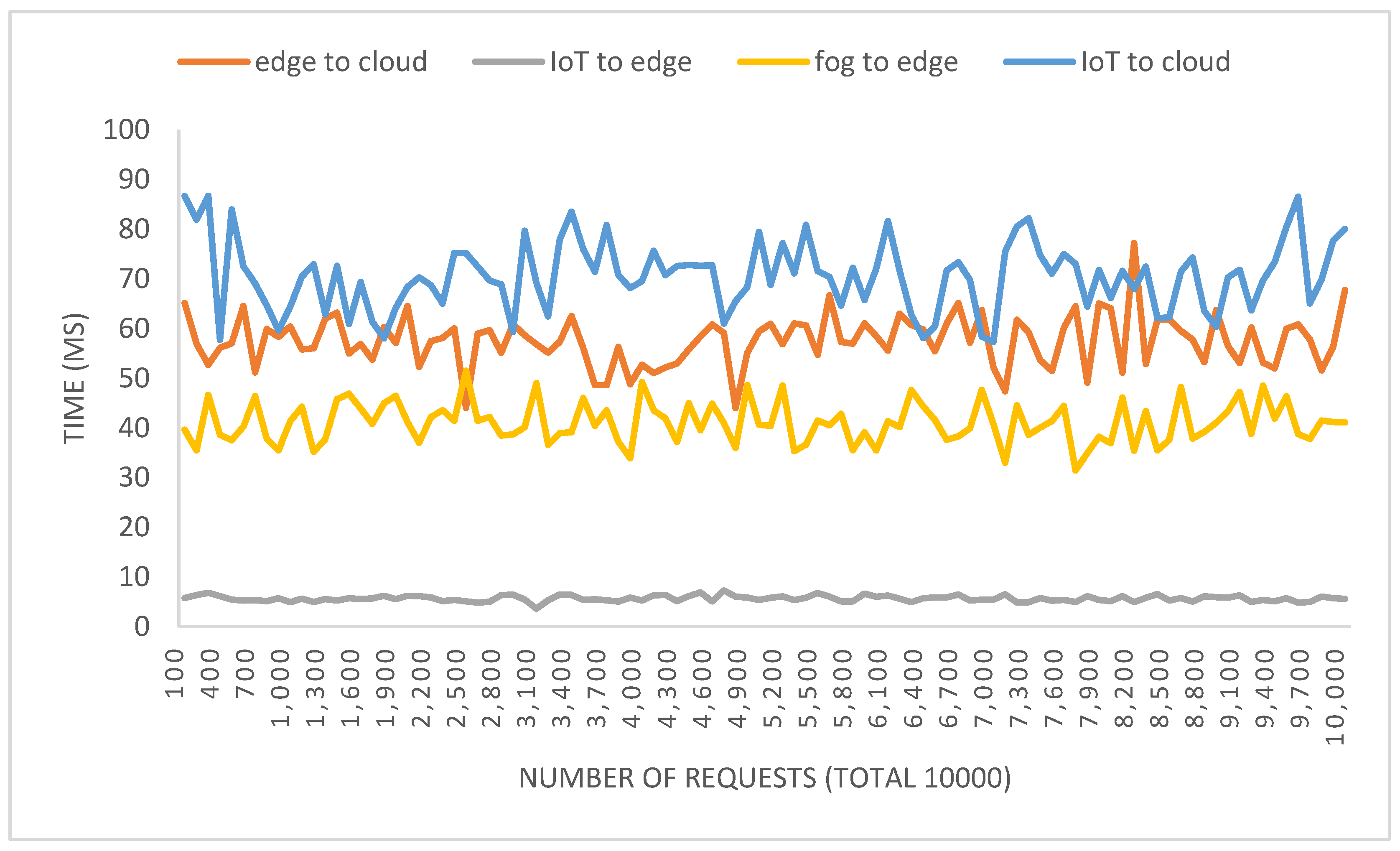
Table 1, the following scenarios are designed to measure both the latency and packet loss between the layers described as (1) edge to cloud, (2) IoT to edge, (3) fog to edge, and (4) IoT to cloud. The test scenarios are executed using the standard ping command, performing 1000 ping commands calculating both average round trip time (RTT) and packet loss rate to simulate the real-time load between actual nodes.
The results obtained from running the abovementioned scenarios are shown in
Figure 9. The average RTT from the edge node to the cloud layer is 56.89 ms, with a packet loss rate of 2.9%. In the second scenario, IoT node to edge node shows an average RTT of 5.67 ms and a packet loss rate of 0.0%. Then, from fog node to edge, the average RTT is 40.42 ms and packet loss rate of 0.17%. Finally, IoT device to cloud shows the highest average RTT 70.37 ms, and the packet loss rate is 3.6%.
This experiment measures the communication latency between the layers and assures that all layers are connected and reachable on the solution topology. The IoT to edge communication has the lowest average RTT, which means this will be the fast communication channel on our test environment infrastructure, making the edge layer the perfect candidate for deploying nodes that require minimized latency.
5.2. Experiment 2—Response Time Measurements
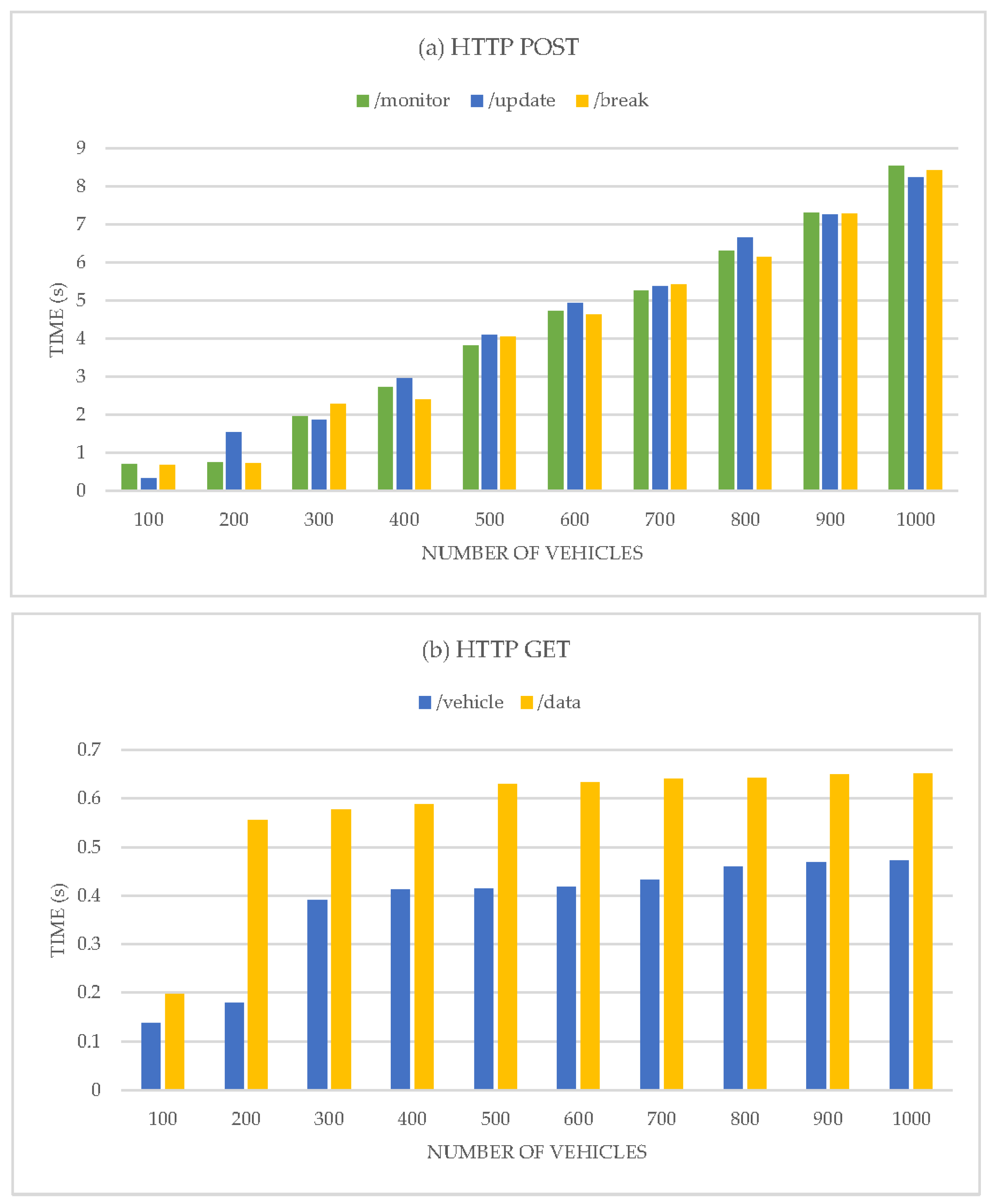
In this experiment, the average response time is tested to evaluate how the system operates under different request loads to guarantee that it will maintain its performance level within the accepted QoS requirements, compared to a single node application hosting different MELs, the same node eliminating the orchestration impact to allow osmotic middleware to be measured without the overload introduced by the osmotic operations. For this experiment, the osmotic middleware stopped the functionality of adding and migrating managed nodes. Simulated requests are periodically sent using JMeter from the IoT devices to different MEL’s microservices. As shown in
Figure 10, the average response time for the HTTP POST request is 4.21 s, which is acceptable due to the operation nature, where the single node application average response time is 3.76 s.
It was also observed that when the number of parallel requests increases, the MELs show accumulatively slower average response time, which is also acceptable, as the numbers are still within QoS requirements values. The same applies to HTTP GET requests; the average response time is 0.42 s which is acceptable compared to 0.27 s for the single node application. The overall results show a satisfactory average response time maintained under the QoS requirements. The optimization of the average response time is not a subject of this research, as code enhancements can accomplish it, so it is measured to confirm that the performance of the middleware does not break the QoS requirements of the solution, which is obtained from the single node application.
5.3. Experiment 3—Orchestration Measurements
This experiment targets to measure the orchestration processes’ performance; the Kubernetes dashboard is installed for visual monitoring for the three clusters (one cluster per layer). Hence, the following scenarios are conducted: (1) orchestration elasticity and (2) MELs/node fault tolerance. The vehicle application is simulated to send a mass request load to the osmotic middle to monitor the existing MELs performance and test the ability to add new MELs to the nodes. Therefore, a load is created with 100,000 requests to the MELs to monitor how the osmotic middleware will respond in terms of this load.
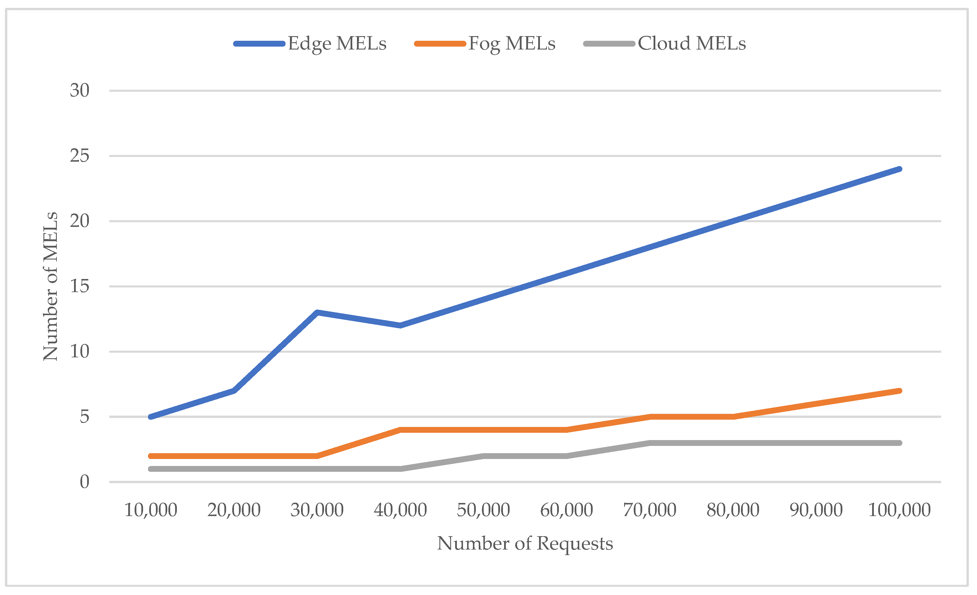
For Experiment [3A], as shown in
Figure 11, the osmotic middleware creates new MELs to handle the growing load with increasing requests. First, the new deployment plan includes edge MELs as a response to the first batch of requests (30,000 requests), which is proven to be expected as shown in previous experiments; the edge node is recognized for its superior average response time. After the first batch, the middleware increases the number of fog MELs with two additional MELs to manage the system overloading. As the requests increase, the middleware decides to increase the cloud nodes with one extra node. It is observed that one MEL decreases the number of edge MELs; this is a MEL migration change request to promote MEL from one layer to another. It is known that migrating a MEL is a complicated request that stops the MEL container and restores it on a different cluster, which adds overhead time to the total processing time.
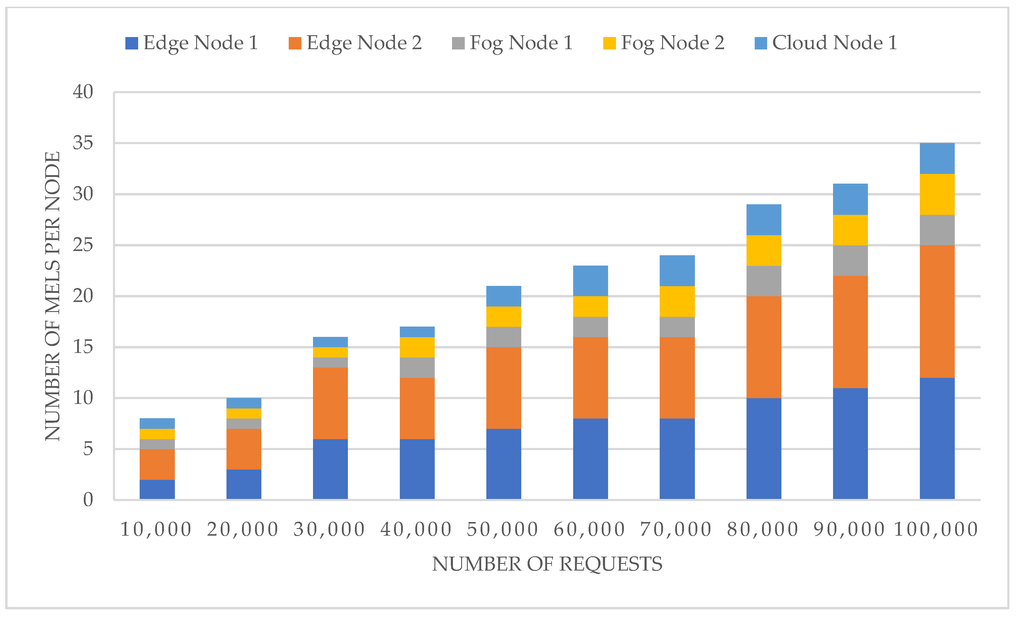
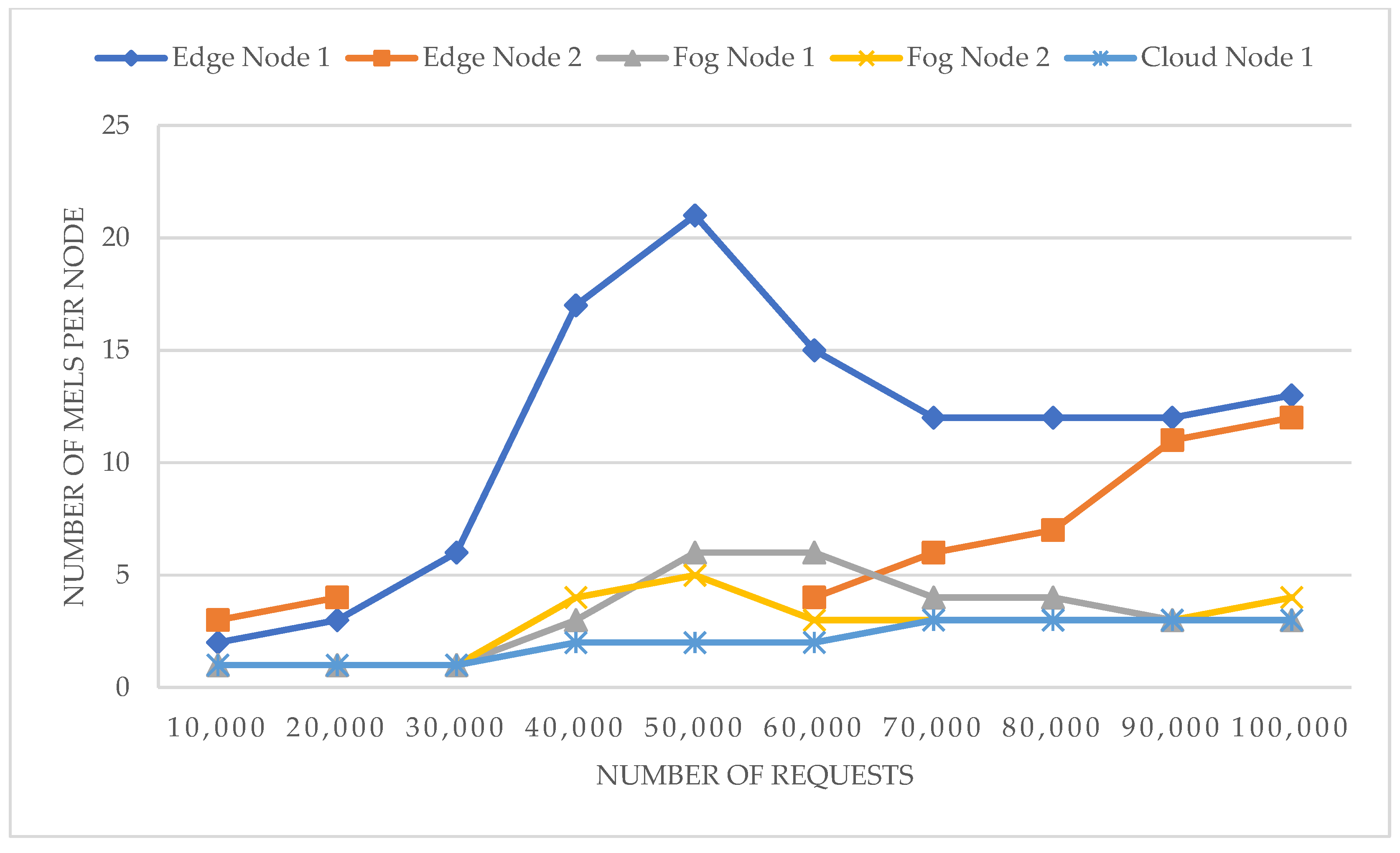
The validation of the MELs re/deployment node selection is conducted on the same experiment, monitoring where the MELs are deployed in terms of node selection. As shown in
Figure 12, the load balance is maintained through rational distribution of the MELs over the participating nodes across the edge, fog, and cloud clusters. The osmotic middleware maintains node utilization as the primary factor of the load distribution, which ensures that the system can handle the mass request load to preserve the QoS requirements.
As shown in
Figure 13 a new experiment is conducted to test the osmotic middleware’s ability to recover in case of a node failure. The experiment is conducted by disconnecting a running edge node to monitor the system recovery. After initiating requests, an edge node (edge node 2) is disconnected by removing it from the network. The osmotic middleware detects the failed node and assigns new MELs to operational nodes, preventing DOS (denial of service error). Meanwhile, the number of assigned MELs is increased severely on the other nodes in an effort to compensate for the performance drop, managing to maintain the system’s QoS requirements. Then, the node is reconnected, allowing the osmotic middleware to start assigning MELs to it. The reconfiguration deployment plan is achieved, allowing MELs redistribution from the other nodes, allowing the osmotic middleware to optimize the MELs distribution over the connected nodes. This experiment ensures that the osmotic middleware can recover any node failure through reconfiguring the system topology, allowing the failing nodes to be reconnected and managed to maintain a balanced distribution during and after the failure recovery process.
5.4. Discussion
Table 2 represents important measurements achieved while performing Experiments 1 and 2 mentioned above. The obtained values show that the proposed model is efficient, where the layers are connected through suitable channels with measured accepted latency. It is to be highlighted that the latency varies between different layers, indicating a faster RTT and reduced packet loss rate from the edge, fog, and cloud, respectively. The software used for testing is not optimal, which is not the focus of this research, as the latency could be enhanced by optimizing the MEL’s microservices and IoT application or even strengthening the nodes capabilities expected from a commercial application.
The proposed middleware demonstrates robustness and elasticity while handling 100 K requests, providing dynamic orchestration of the system via a self-managed reconfiguration, as shown in
Table 3.
The load distribution for the nodes is shown in
Table 4. It shows a balanced distribution for the nodes based on the provisioning data by utilizing the optimized dynamic Hungarian algorithm to choose the selected target node for deployment. Additionally, cost efficiency is indicated while terminating the unutilized MELs, offering fewer computation, memory, and power consumption, as these factors are vital when optimizing any distributed system.
Table 5 demonstrates osmotic middleware resilience, showing how the middleware utilizes dynamic orchestration in case of node failure. The failed node is automatically removed from the topology, executing a new load redistribution and maintaining overall system performance. Due to the limited resources, edge nodes are potentially vulnerable to failure due to the lack of a stable power supply, as they are usually hosted either on-site or on a local data center; hence, a failure recovery module is presented by the osmotic middleware.
6. Conclusions
In this paper, osmotic middleware was presented, inheriting the principles of osmotic computing and utilizing edge, fog, and cloud resources, providing a managing platform for various end-to-end IoT applications. The osmotic middleware implements the MAPE-K reference model for establishing the orchestration of the provisioning data feedback stored on the shared knowledge database. The optimized dynamic Hungarian algorithm was chosen to solve the node selection for dynamic orchestration to manage a balanced load distribution. The proposed model addressed multiple QoS attributes, including efficiency, robustness, elasticity, and cost efficiency.
The osmotic middleware was evaluated using a real-time application and a simulated load. The conducted experiments validated the system with regard to latency, average response time, and the orchestration processes performance indicators. This osmotic middleware is proven to provide a self-maintained adaptable end-to-end IoT system through feedback loops from the nodes provisioning for both infrastructure and application performance matrices. Moreover, the system is demonstrated to achieve three main characteristics: container-based execution, dynamic on-demand resource orchestration, and provisioning-based load distribution.
Our future work will concentrate on leveraging the present osmotic middleware design to implement blockchain technologies, addressing the security and privacy issues introduced by the decentralized computational model, especially those emerging with the IoT spectrum as personal/sensitive data are transferred among different layers. Moreover, dynamic orchestration comes with the cost of compromising the system integrity by attack threats, including fake MELs injection, which are to be also prevented by integrating osmotic middleware with permission blockchains.
In addition, we will perform a comprehensive review of the possibilities for an artificial-intelligence-based method for decision reasoning in the deployment plan, targeting the optimization of the designated parameters (e.g., reducing latency), which would reduce the provisioning data sent by the agent to the provisioning engine advances, with less network overhead and better performance. The provisioning data will also be used to predict and mitigate node failure situations.


