
Low Temperature Plasma Nitriding of Inner Surfaces in Stainless Steel Mini-/Micro-Pipes and Nozzles


Abstract
:1. Introduction
2. Experimental Procedure
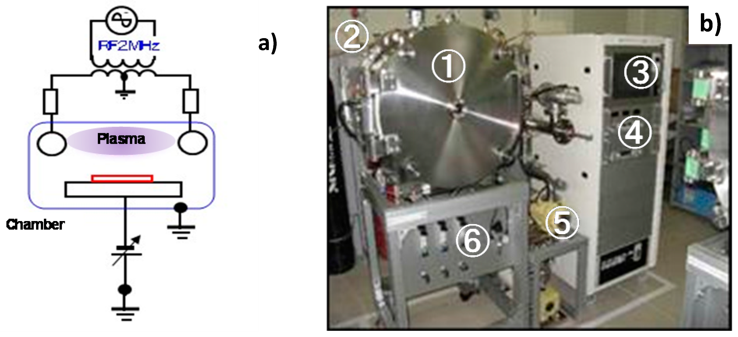
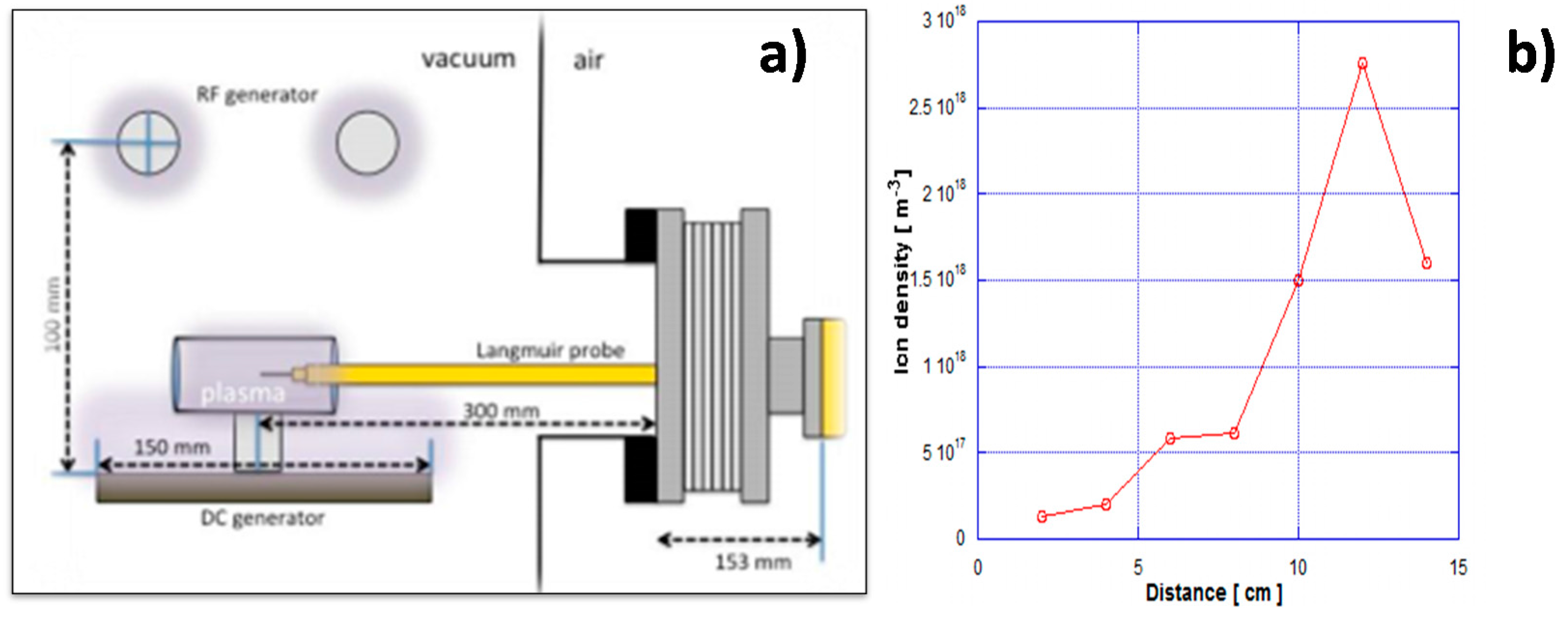
2.1. RF-DC Plasma Generation System
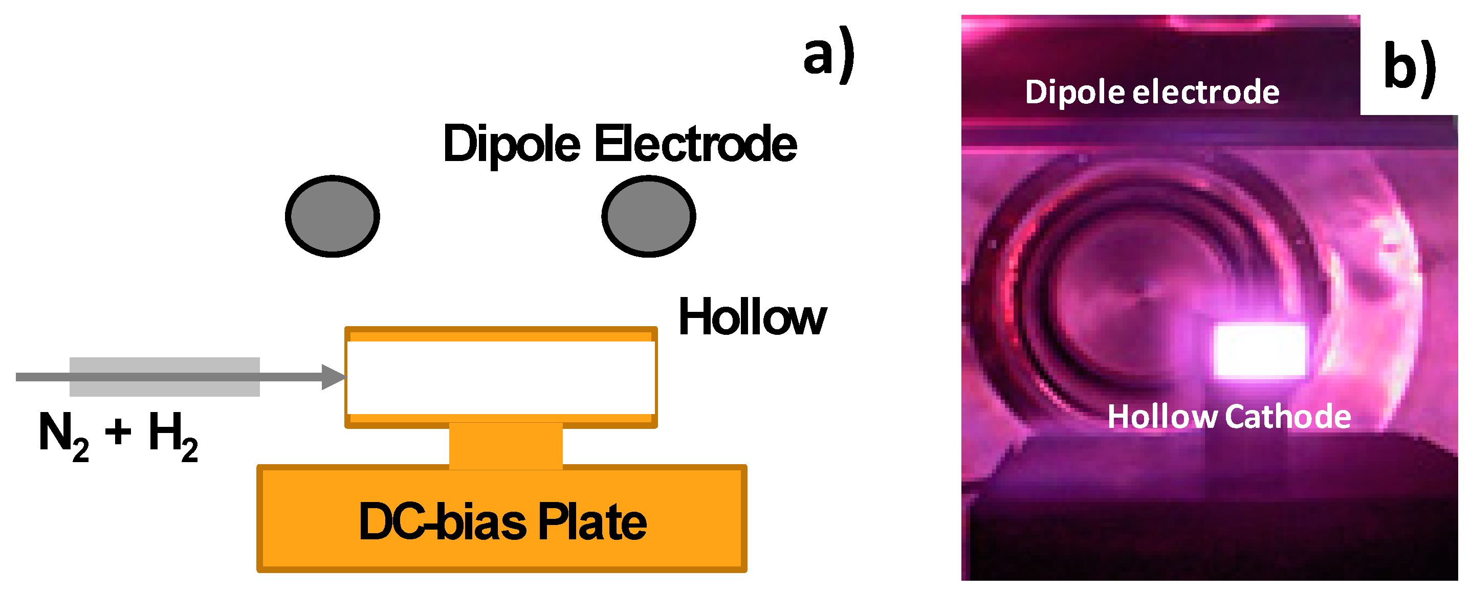
2.2. Hollow Cathode Device
2.3. Specimen
3. Experimental Results
3.1. Plasma Nitriding of AISI316 Stainless Steel Pipe
3.2. Plasma Nitriding of AISI304 Mini-Pipe
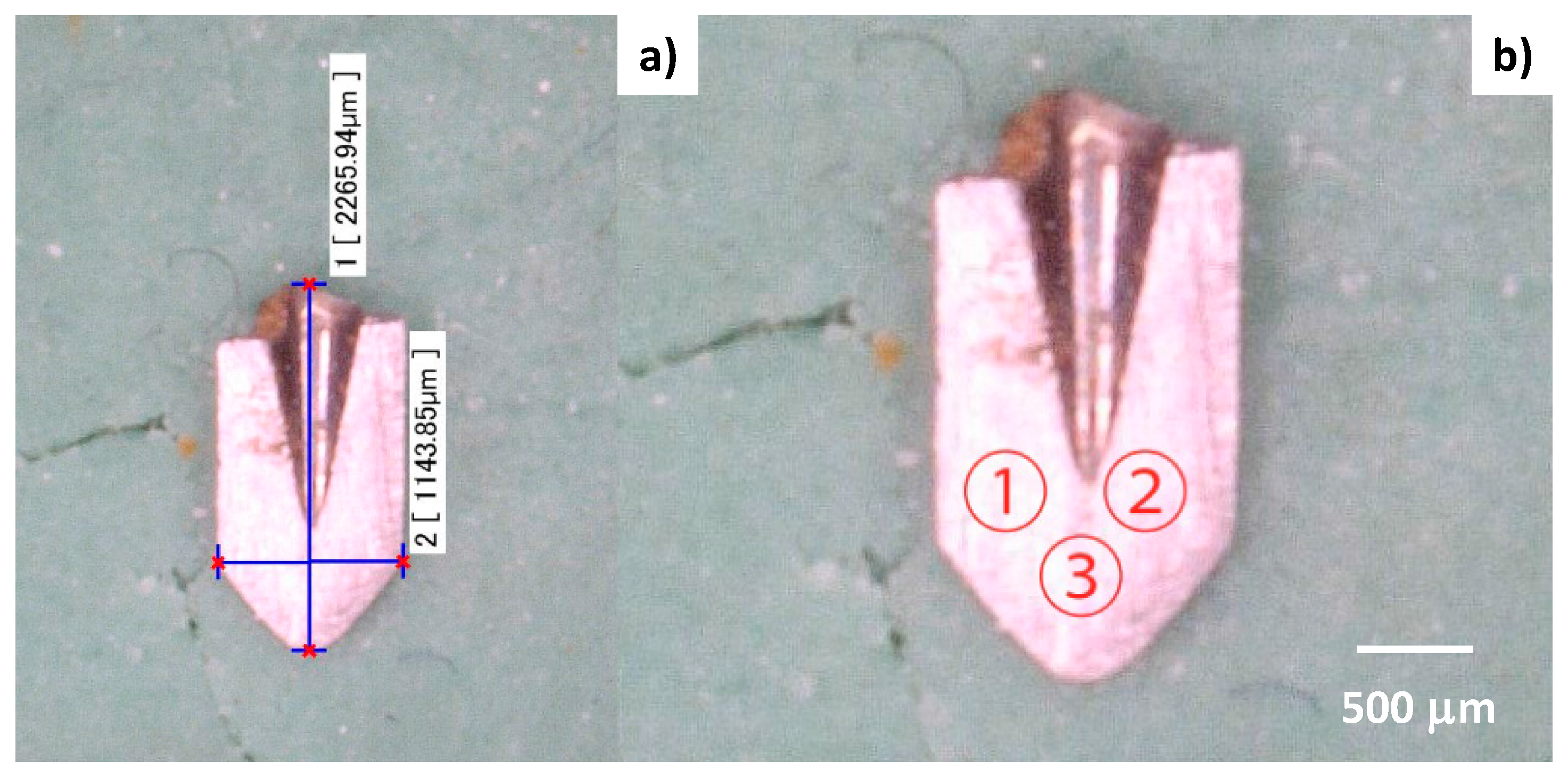
3.3. Plasma Nitriding of the Mini-Nozzle
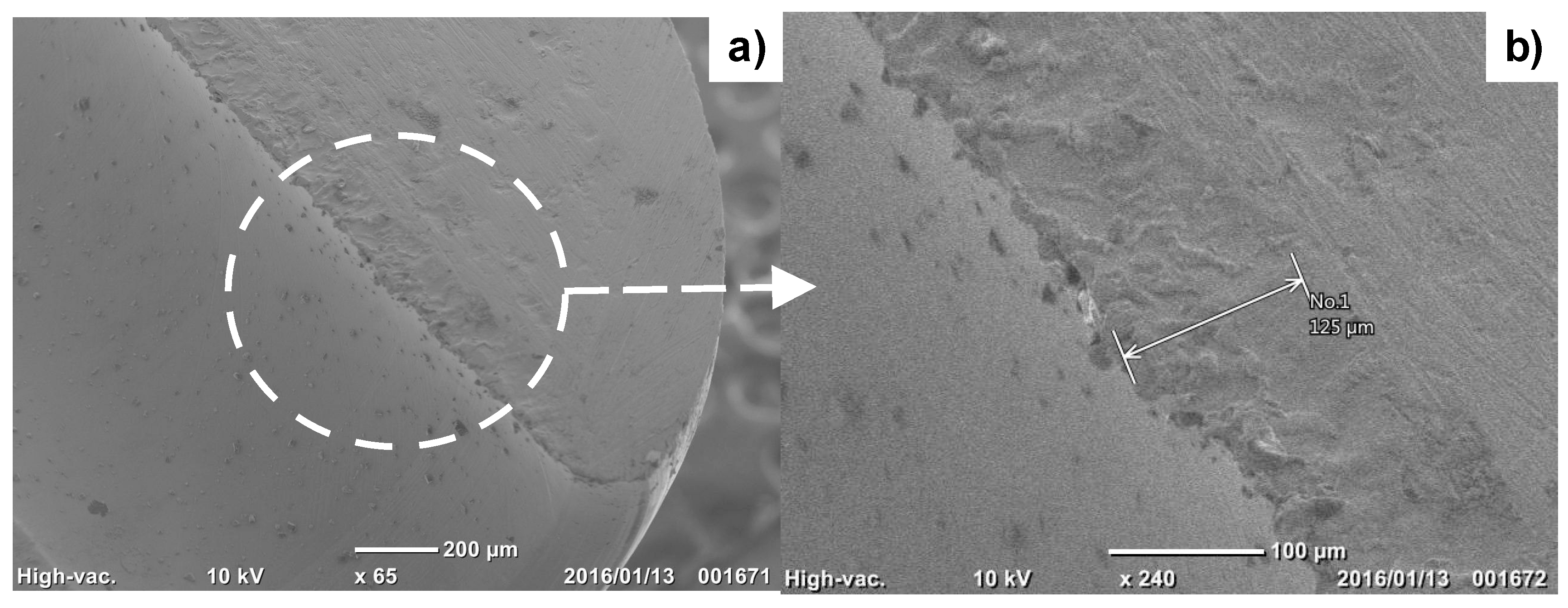
3.4. Plasma Nitriding of Micro-Nozzle
4. Discussion
5. Conclusions
Acknowledgments
Author Contributions
Conflicts of Interest
References
- TecDia. Catalogue of Nozzles. 2016. Available online: http://www.tecdia.com/jp/products/precision/dispenser/index.php (accessed on 10 May 2017).
- Resigen, U.; Scheik, S. Multi-dimensional line dispensing of unfilled adhesives. Microsyst. Technol. 2008, 14, 1895–1901. [Google Scholar] [CrossRef]
- Katoh, T.; Aizawa, T.; Yamaguchi, T. Plasma assisted nitriding for micro-texturing martensitic stainless steels. Manuf. Rev. 2015, 2, 2. [Google Scholar] [CrossRef]
- Aizawa, T.; Fukuda, T.; Morita, T. Low temperature high density plasma nitriding of stainless steel molds for stamping of oxide glasses. Manuf. Rev. 2016, 3, 2. [Google Scholar] [CrossRef]
- Windajanti, J.M.; Aizawa, T.; Djoko, H.S. High density plasma nitriding of pure titanium. In Proceedings of the 10th SEATUC Conference 2016, Tokyo, Japan, 22–24 February 2016. [Google Scholar]
- Aizawa, T.; Muraishi, S.; Sugita, Y. High density plasma nitriding of Al-Cu alloys for automotive parts. J. Phys. Sci. Appl. 2014, 4, 255–261. [Google Scholar]
- Kim, S.K.; Yoo, J.S.; Priest, J.M.; Fewell, M.P. Characteristics of martensitic stainless steel nitrided in a low-pressure RF plasma. Surf. Coat. Technol. 2003, 163, 380–385. [Google Scholar] [CrossRef]
- Farghali, A.; Aizawa, T. Phase transformation induced by high nitrogen content solid solution in the martensitic stainless steels. Mater. Trans. 2017, 58, 697–700. [Google Scholar] [CrossRef]
- Samandi, M.; Shedden, B.A.; Smith, D.I.; Collins, G.A.; Hutchings, R.; Tendys, H. Microstructure, corrosion and tribological behavior of plasma immersion ion-implanted austenitic stainless steel. Surf. Coat. Technol. 1993, 59, 261–266. [Google Scholar] [CrossRef]
- Blawert, C.; Mordike, B.L.; Jiraskova, Y.; Schneeweiss, O. Structure and composition of expanded austenite produced by nitrogen plasma immersion ion implantation of stainless steels X6CrNiTi1810 and X2CrNiMoN2253. Surf. Coat. Technol. 1999, 116, 189–198. [Google Scholar] [CrossRef]
- Farghali, A.; Aizawa, T. High nitrogen concentration on the fine grained austenitic stainless steels. In Proceedings of the 11th SEATUC Conference, Ho Chi Minh City, Vietnam, 13–14 March 2017. [Google Scholar]
- Aizawa, T.; Sugita, Y. High density RF-DC plasma nitriding of steels for die and mold technologies. Res. Rep. SIT 2013, 57, 1–10. [Google Scholar]
- Anzai, M. Surface Treatment for High Qualification of Dies and Molds; Nikkan-Kougyo Shinbun: Tokyo, Japan, 2009. [Google Scholar]
- Dong, H. S-phase surface engineering of Fe-Cr, Co-Cr and Ni-Cr alloys. Int. Mater. Rev. 2010, 55, 65–98. [Google Scholar] [CrossRef]
- Santjojo, D.J.; Istiroyah; Aizawa, T. Dynamics of nitrogen and hydrogen species in a high rate plasma nitriding of martensitic stainless steel. In Proceedings of the 9th SEATUC Conference, Nakhon Ratchasima, Thailand, 27–30 July 2015. [Google Scholar]
- Yunata, E.E. Characterization and Application of Hollow Cathode Oxygen Plasma. Ph.D. Thesis, Shibaura Institute of Technology, Tokyo, Japan, 2016. [Google Scholar]
- Czerwiec, T.; Michel, H.; Bergmann, E. Low-pressure, high-density plasma nitriding: Mechanisms, technology and results. Surf. Coat. Technol. 1998, 108–109, 182–190. [Google Scholar] [CrossRef]
- Aizawa, T.; Sugita, Y. Distributed plasma nitriding systems for surface treatment of miniature functional products. In Proceedings of the 9th 4M/ICOMM, Milan, Italy, 31 March–2 April 2015; pp. 449–453. [Google Scholar]
- Ferreira, L.M.; Brunatto, S.F.; Cardoso, R.P. Martensitic stainless steels low-temperature nitriding: Dependence of substrate composition. Mater. Res. 2015, 18, 622–627. [Google Scholar] [CrossRef]


| Pipe and Nozzle | Length | Outer Diameter at Outlet | Thickness at Outlet | Inner Diameter at Outlet | Surface Roughness Rz | Outlook | Material Supplier |
|---|---|---|---|---|---|---|---|
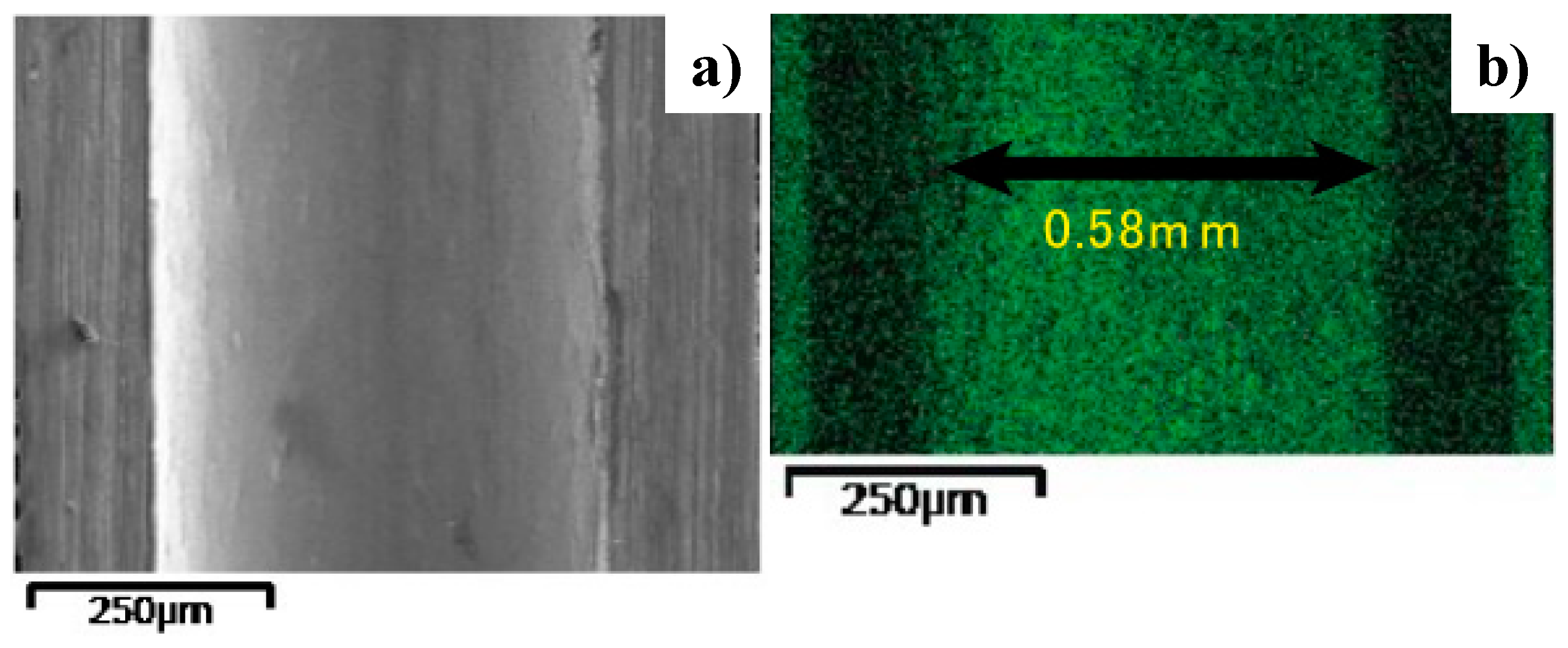
| AISI304 Micro-Pipe | 30.0 mm | 0.88 mm | 0.15 mm | 0.58 mm | 0.5 μm | 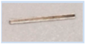 | TECDIA Co., Ltd. |
| AISI316 Pipe | 55.5 mm | 21.5 mm | 2.3 mm | 16.9 mm | 1.5 μm |  | Tokai Engineering Service, Co., Ltd. |
| AISI316 Mini-Nozzle | 25.0 mm | 2.8 mm | 0.86 mm | 1.08 mm | 1.2 μm |  | Tokai Engineering Service, Co., Ltd. |
| AISI304 Micro-Nozzle | 5.5 mm | 1.9 mm | 0.5 mm | 1.0 mm | 0.5 μm | 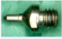 | TECDIA Co., Ltd. |
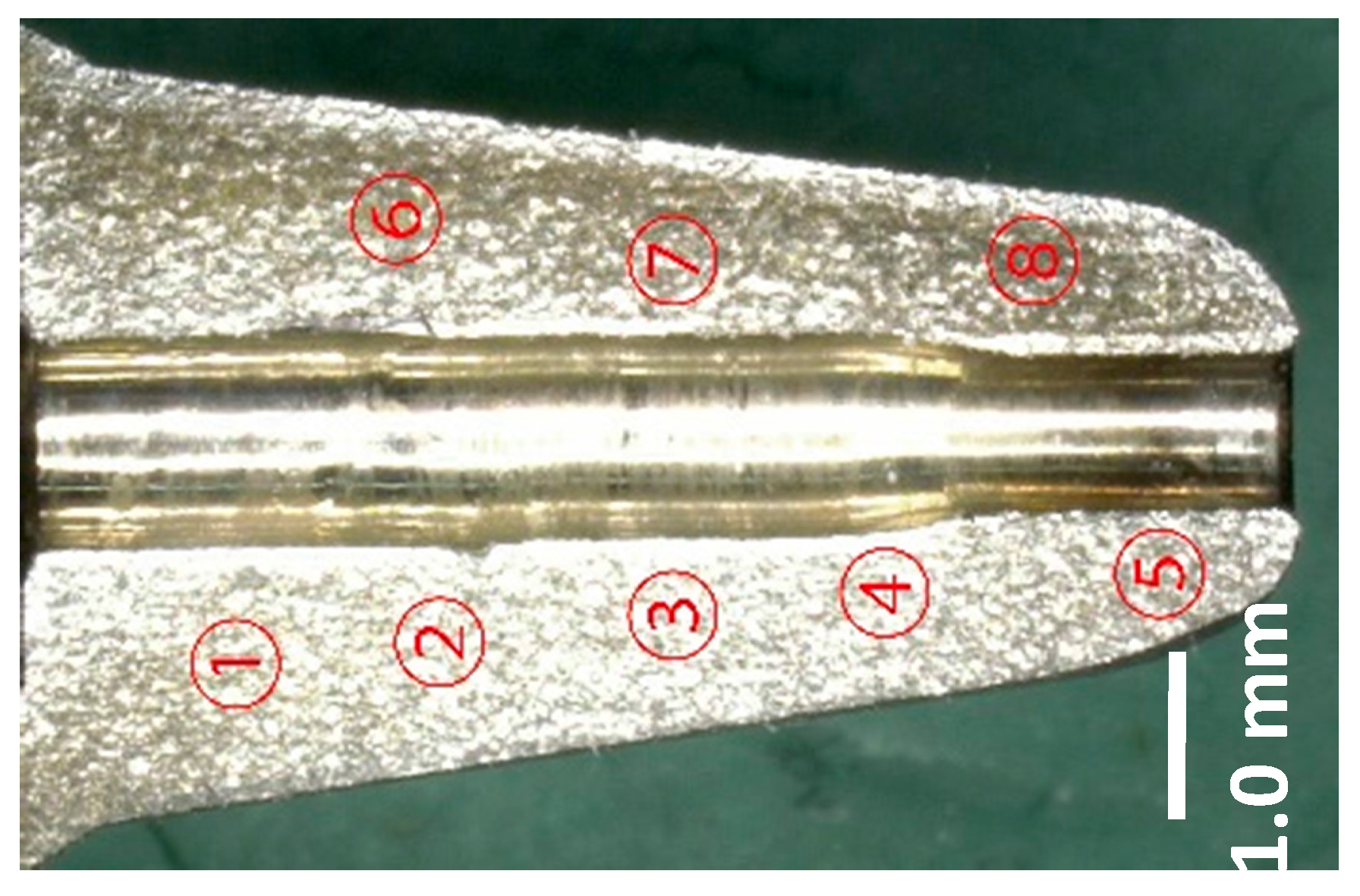
| Position in Figure 4 | Micro-Vickers Hardness |
|---|---|
| #1 | 530 HV ± 15 HV |
| #2 | 390 HV ± 20 HV |
| #3 | 660 HV ± 10 HV |
| #4 | 750 HV ± 15 HV |
| #5 | 820 HV ± 20 HV |
| #6 | 380 HV ± 10 HV |
| #7 | 690 HV ± 20 HV |
| #8 | 600 HV ± 15 HV |
| Position in Figure 6 | Micro-Vickers Hardness |
|---|---|
| #1 | 960 HV ± 30 HV |
| #2 | 880 HV ± 20 HV |
| #3 | 1020 HV ± 15 HV |
© 2017 by the authors. Licensee MDPI, Basel, Switzerland. This article is an open access article distributed under the terms and conditions of the Creative Commons Attribution (CC BY) license (http://creativecommons.org/licenses/by/4.0/).
Share and Cite
Aizawa, T.; Wasa, K. Low Temperature Plasma Nitriding of Inner Surfaces in Stainless Steel Mini-/Micro-Pipes and Nozzles. Micromachines 2017, 8, 157. https://doi.org/10.3390/mi8050157
Aizawa T, Wasa K. Low Temperature Plasma Nitriding of Inner Surfaces in Stainless Steel Mini-/Micro-Pipes and Nozzles. Micromachines. 2017; 8(5):157. https://doi.org/10.3390/mi8050157
Chicago/Turabian StyleAizawa, Tatsuhiko, and Kenji Wasa. 2017. "Low Temperature Plasma Nitriding of Inner Surfaces in Stainless Steel Mini-/Micro-Pipes and Nozzles" Micromachines 8, no. 5: 157. https://doi.org/10.3390/mi8050157
APA StyleAizawa, T., & Wasa, K. (2017). Low Temperature Plasma Nitriding of Inner Surfaces in Stainless Steel Mini-/Micro-Pipes and Nozzles. Micromachines, 8(5), 157. https://doi.org/10.3390/mi8050157