
Design and Experimental Research of a Novel Stick-Slip Type Piezoelectric Actuator


Abstract
:1. Introduction
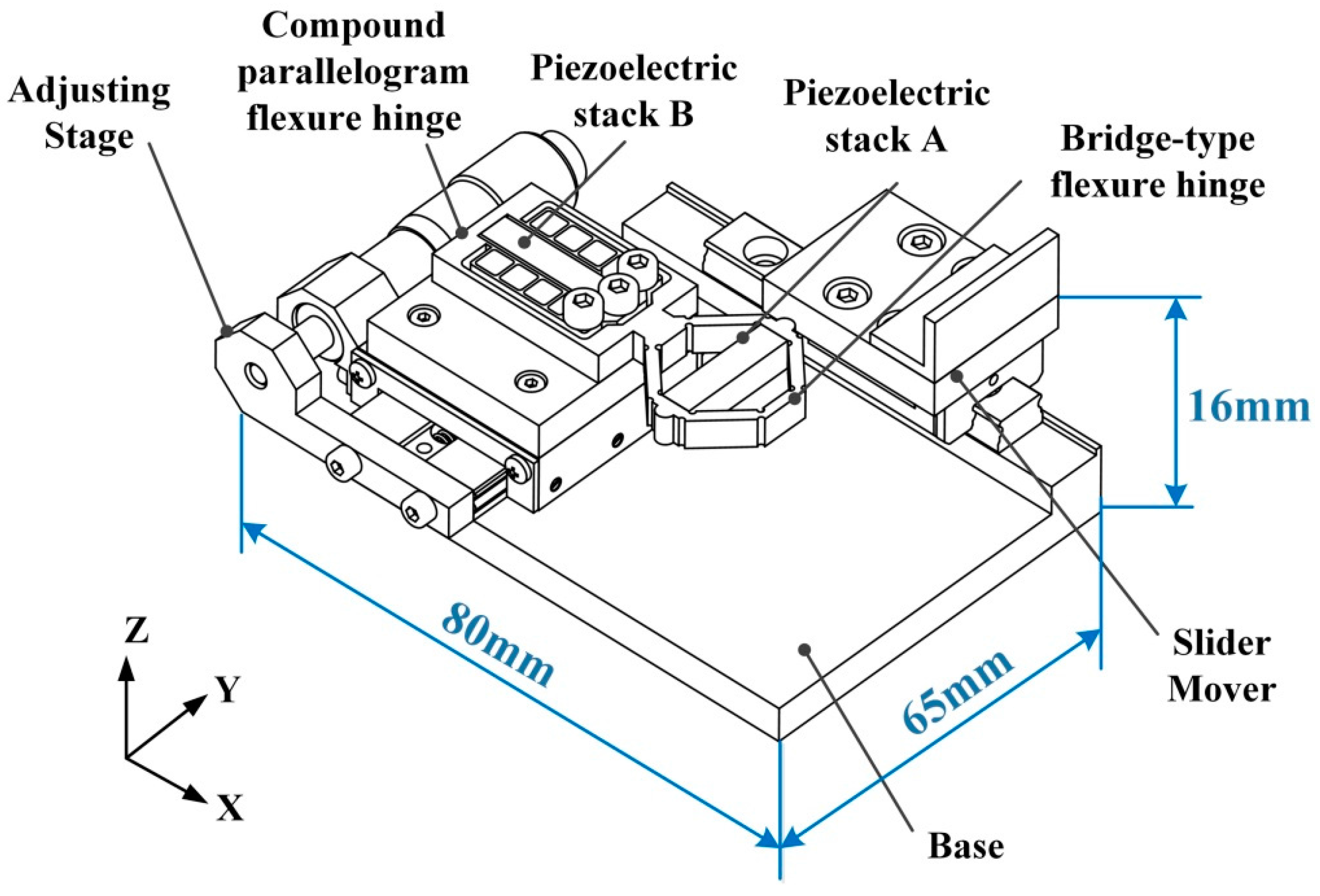
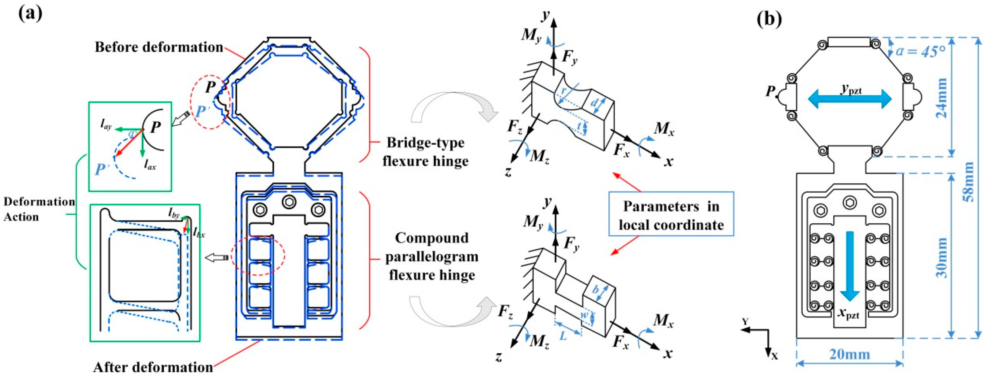
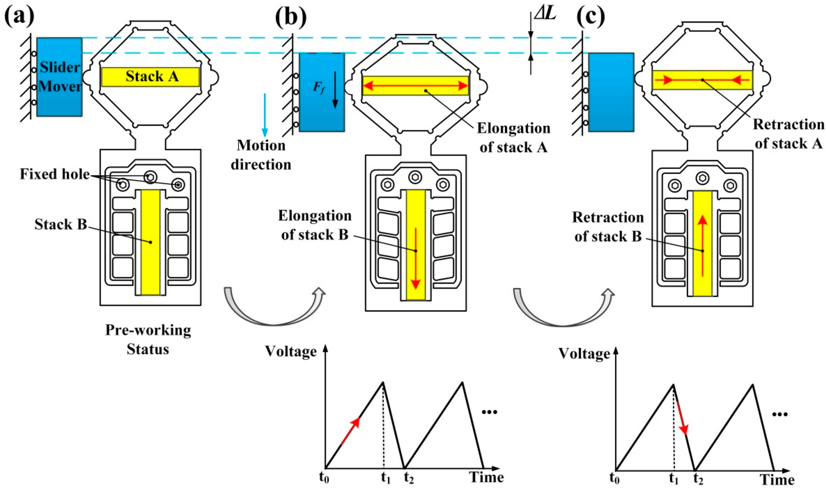
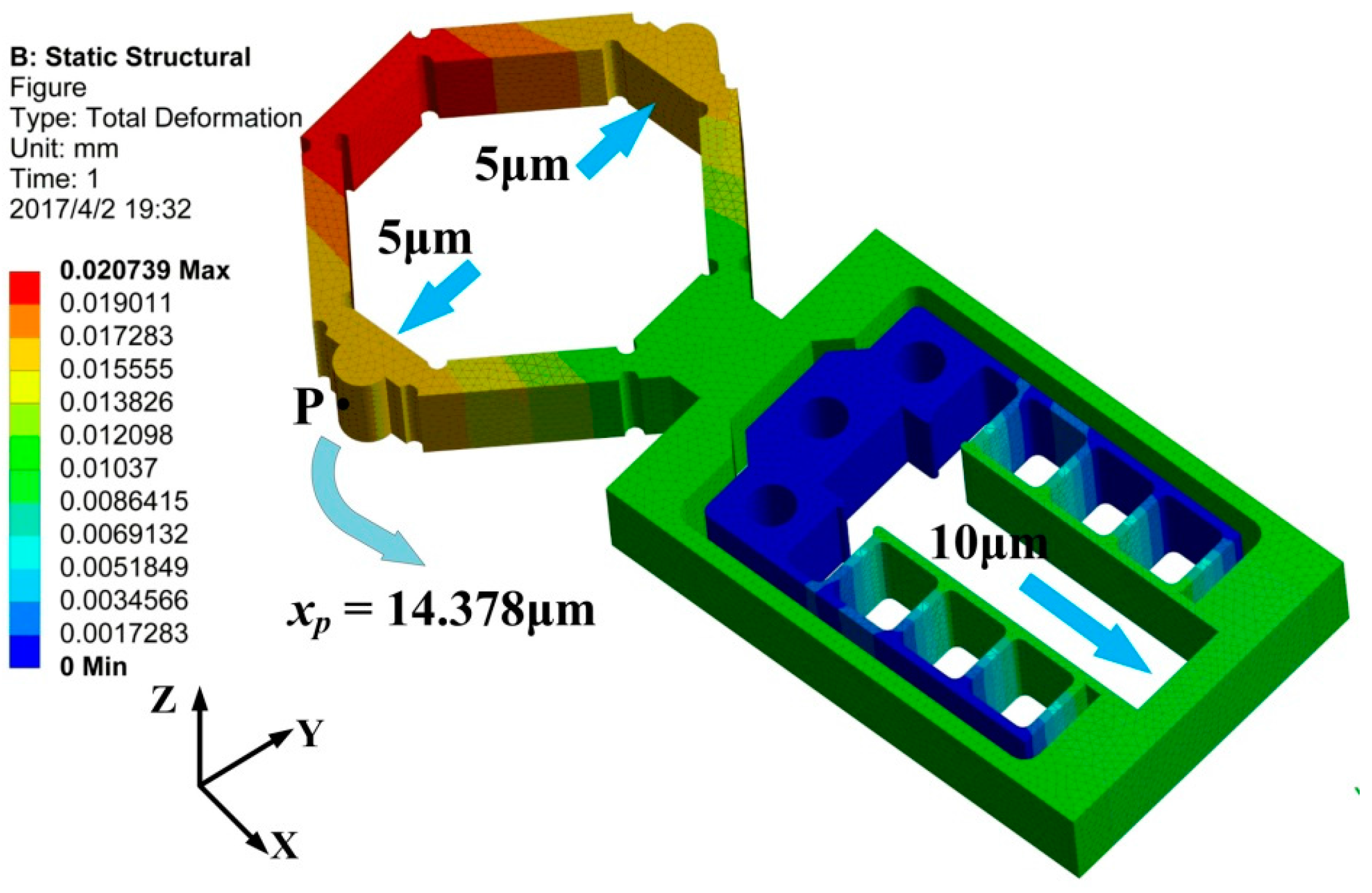
2. Design and Analysis
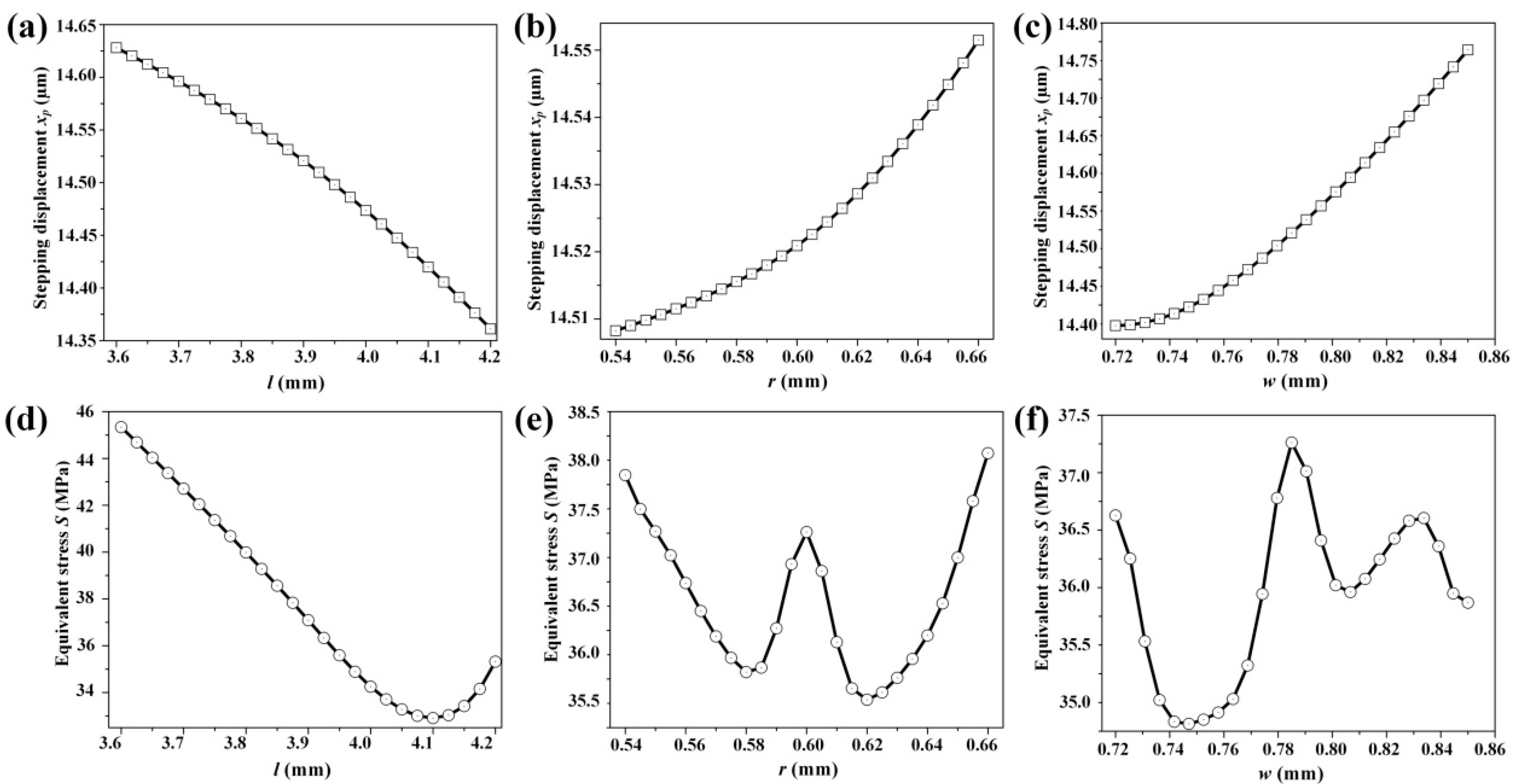
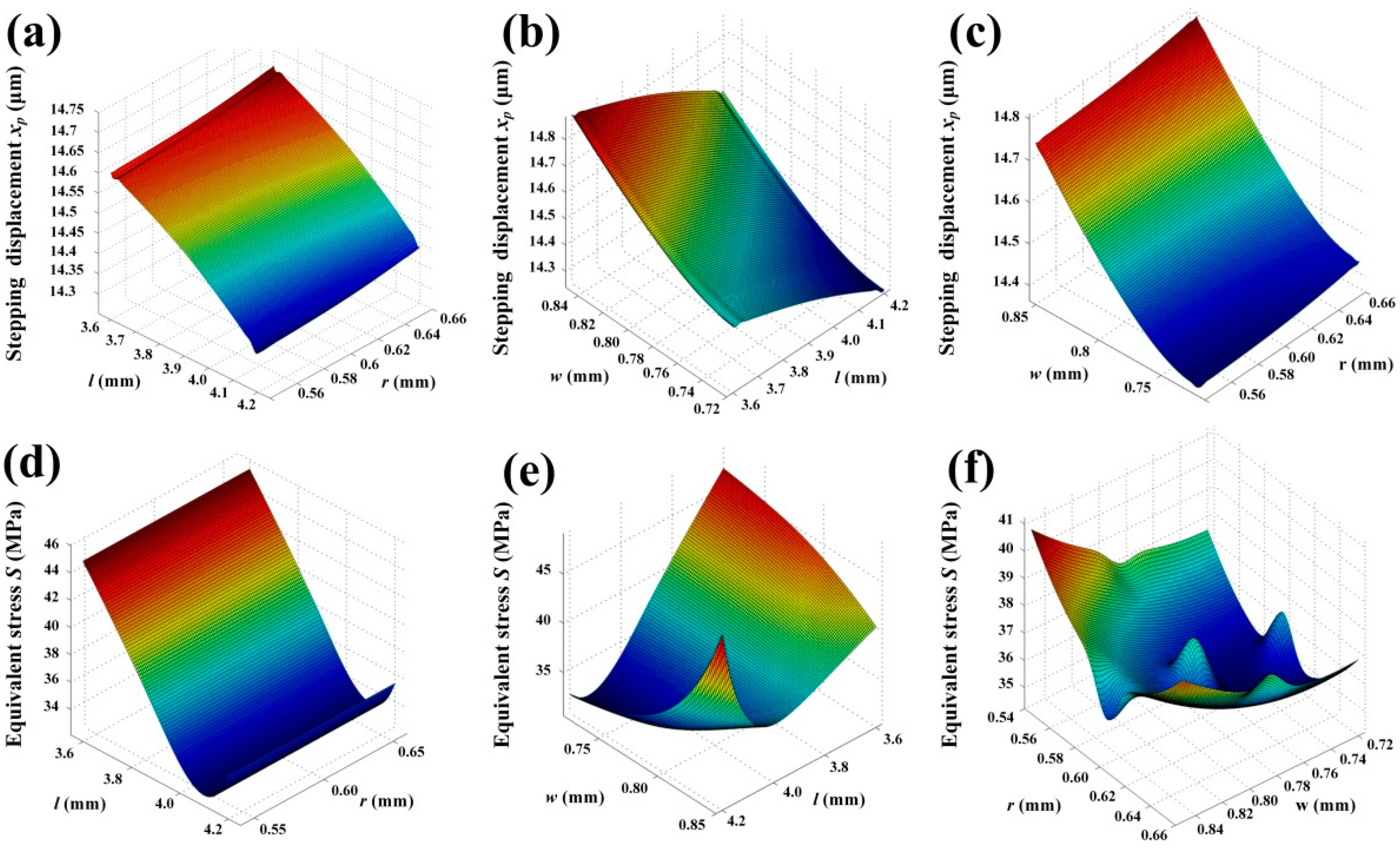
3. Optimization
4. Experiment
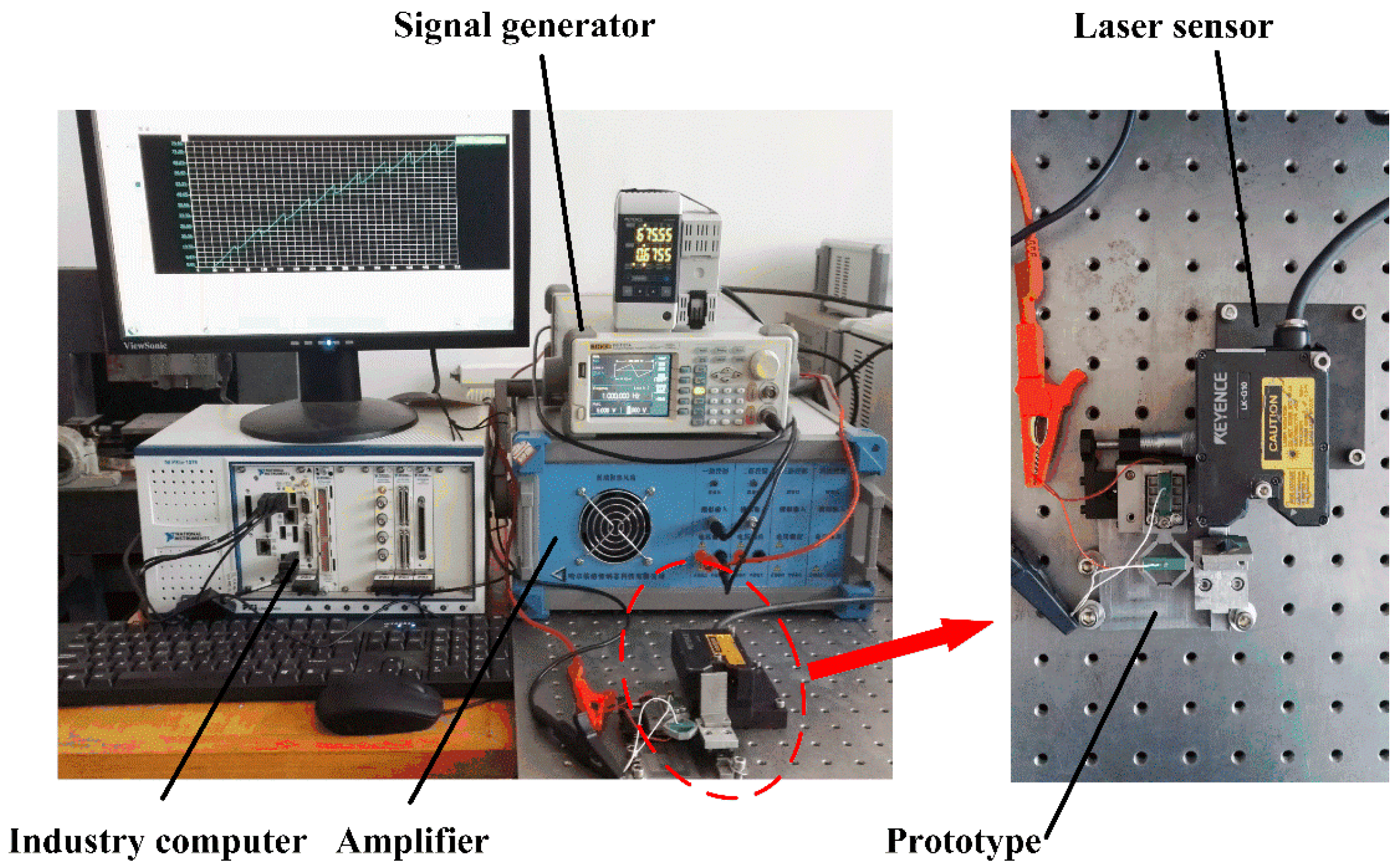
4.1. Experimental Setup
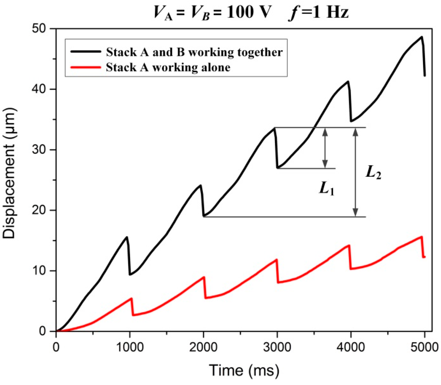
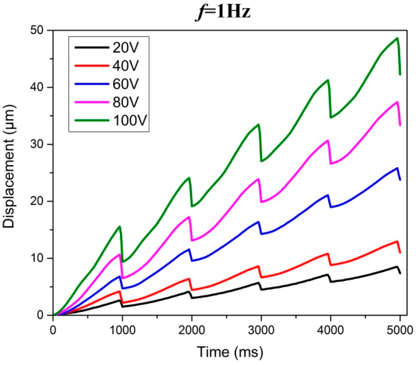
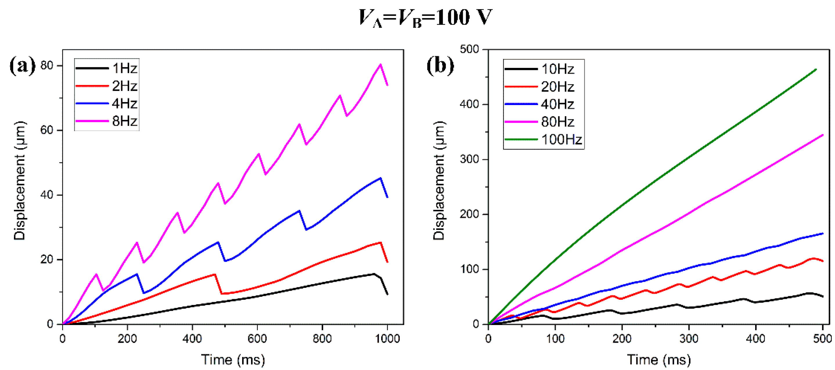
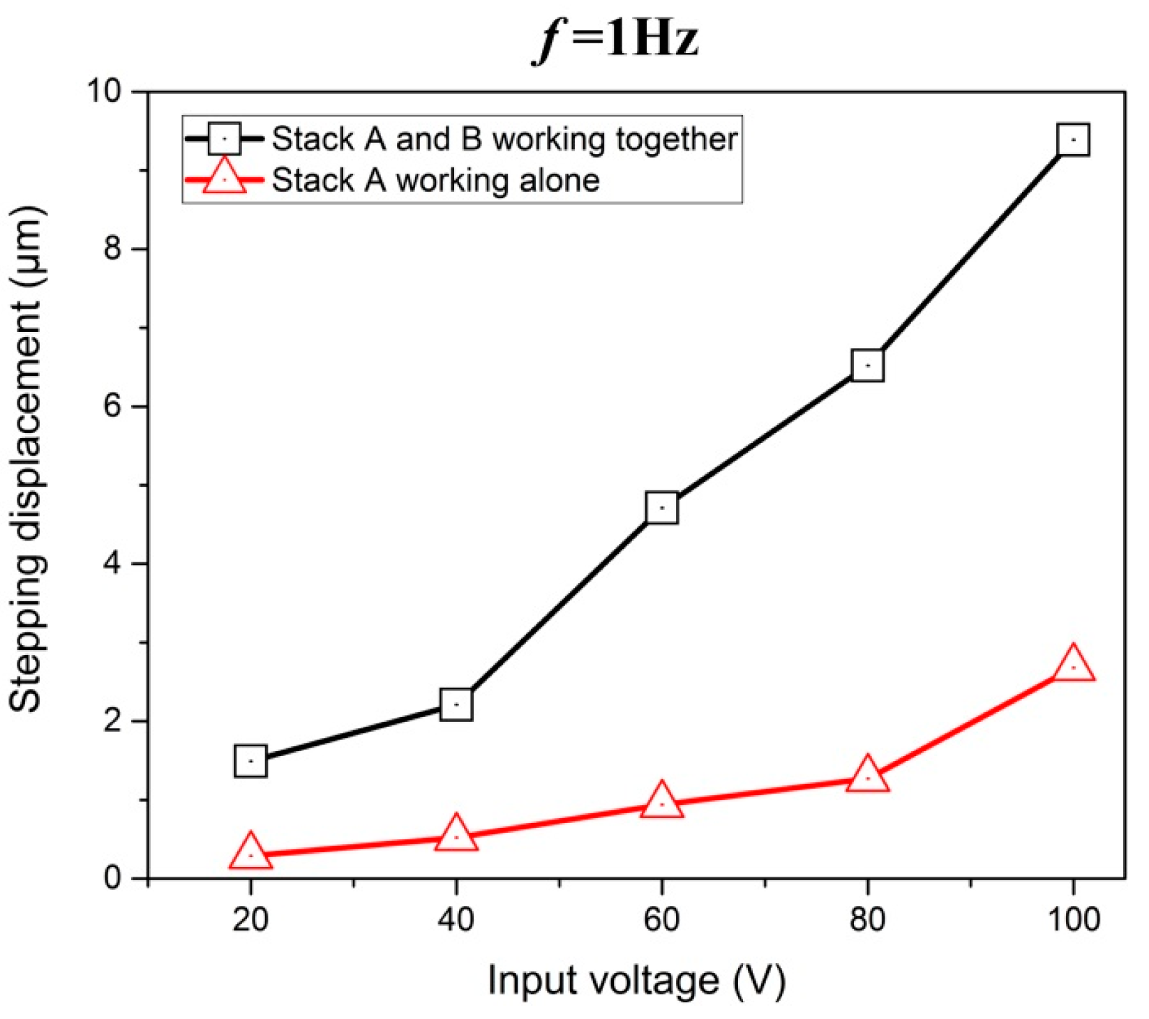
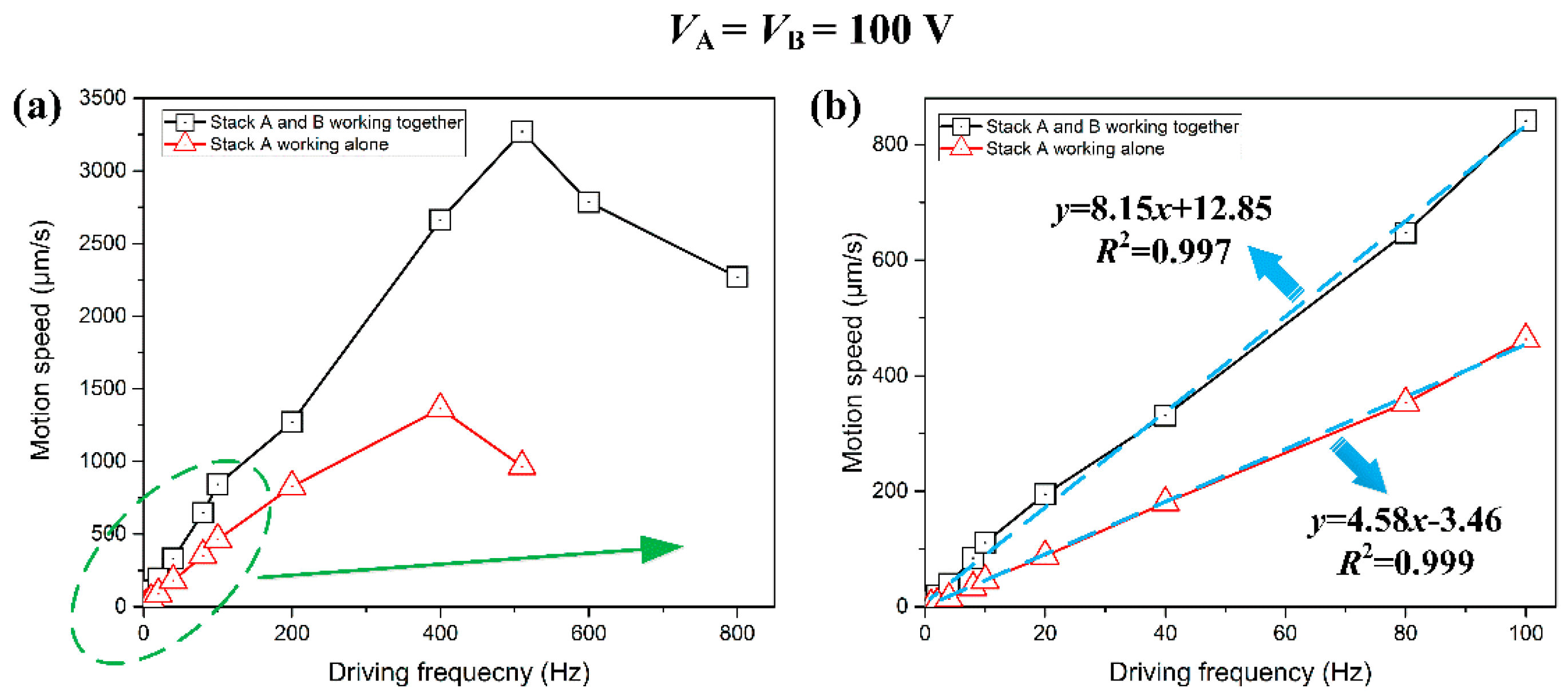
4.2. Motion Performance Tests
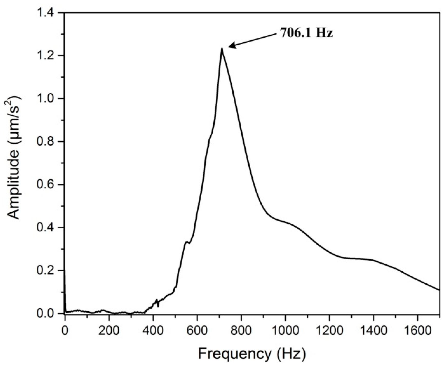
4.3. First Resonance Frequency Tests
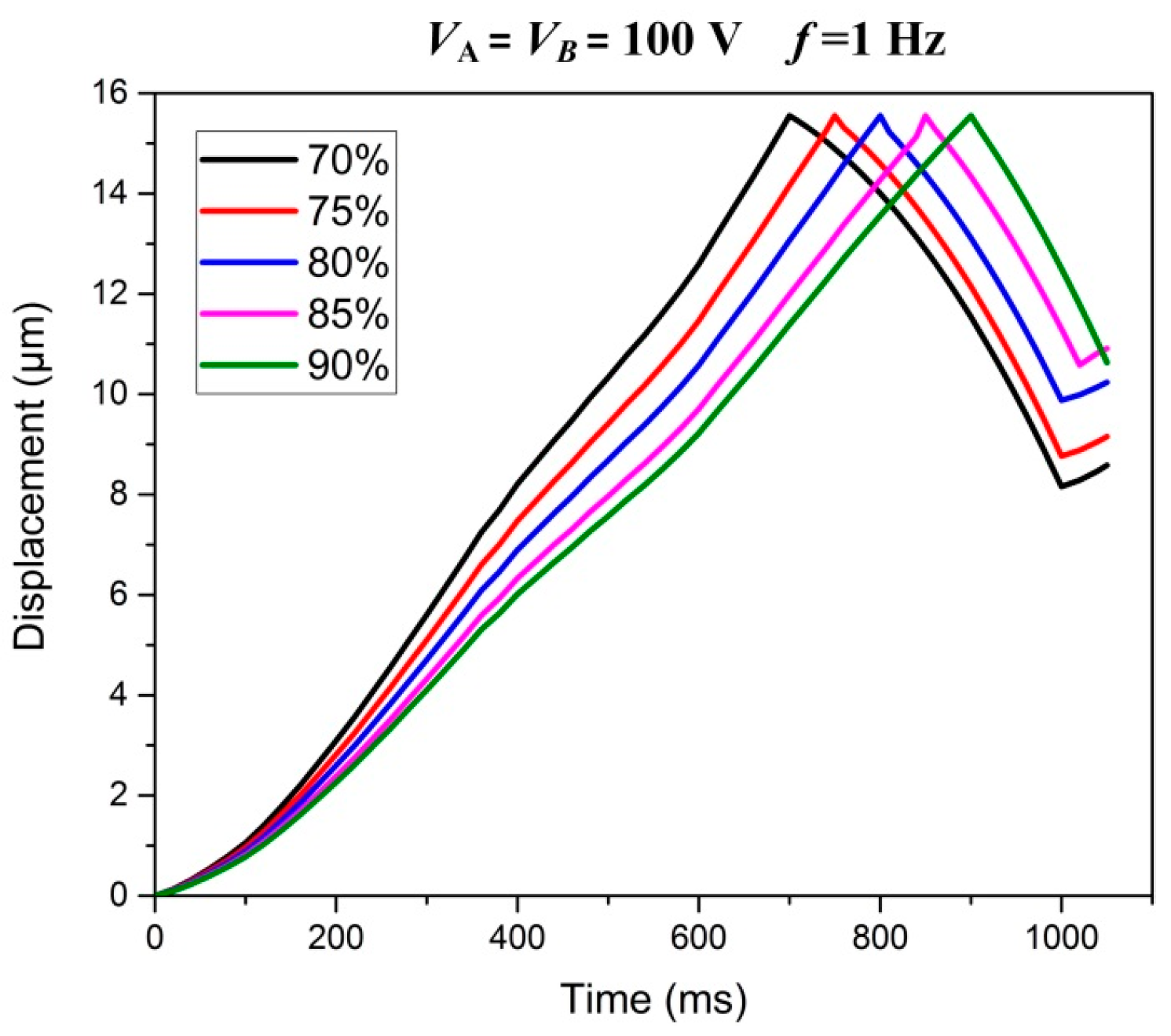
4.4. Electrical Loading Rates Tests
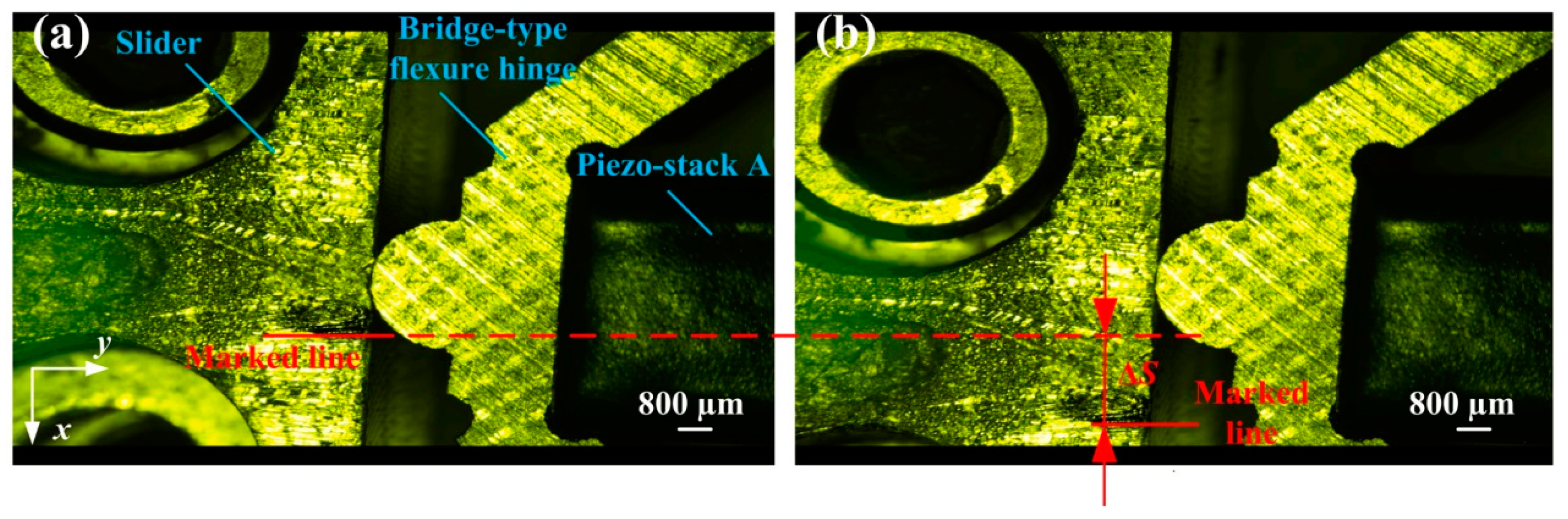
4.5. In Situ Observation of the Stick-Slip Process
5. Conclusions
Supplementary Materials
Acknowledgments
Author Contributions
Conflicts of Interest
References
- Yong, Y.K.; Moheimani, S.O.R.; Kenton, B.J.; Leang, K.K. Invited Review Article: High-speed flexure-guided nanopositioning: Mechanical design and control issues. Rev. Sci. Instrum. 2012, 83, 802–843. [Google Scholar] [CrossRef] [PubMed]
- Tian, Y.; Zhang, D.; Shirinzadeh, B. Dynamic modelling of a flexure-based mechanism for ultra-precision grinding operation. Precis. Eng. 2011, 35, 554–565. [Google Scholar] [CrossRef]
- Polit, S.; Dong, J. Development of a High-Bandwidth XY Nanopositioning Stage for High-Rate Micro-/Nanomanufacturing. IEEE/ASME Trans. Mechatron. 2011, 16, 724–733. [Google Scholar] [CrossRef]
- Hou, X.; Lee, H.P.; Ong, C.J.; Lim, S.P. Development and numerical characterization of a new standing wave ultrasonic motor operating in the 30–40 kHz frequency range. Ultrasonics 2013, 53, 928–934. [Google Scholar] [CrossRef] [PubMed]
- Lim, K.J.; Lee, J.S.; Park, S.H.; Kang, S.H.; Kim, H.H. Fabrication and characteristics of impact type ultrasonic motor. J. Eur. Ceram. Soc. 2007, 27, 4159–4162. [Google Scholar] [CrossRef]
- Fernandez, J.M.; Perriard, Y. Comparative analysis and modeling of both standing and travelling wave ultrasonic linear motor. In Proceedings of the 2003 IEEE Symposium on Ultrasonics, Honolulu, HI, USA, 5–8 October 2003; Volume 2, pp. 1770–1773. [Google Scholar]
- Park, K.H.; Lee, J.H.; Kim, S.H.; Kwark, Y.K. High speed micro positioning system based on coarse/fine pair control. Mechatronics 1995, 5, 645–663. [Google Scholar] [CrossRef]
- Wu, Z.; Li, Y. Design, Modeling, and Analysis of a Novel Microgripper Based on Flexure Hinges. Adv. Mech. Eng. 2014, 8, 1–11. [Google Scholar] [CrossRef]
- Li, C.; Gu, G.; Zhu, L.; Su, C. Odd-harmonic repetitive control for high-speed raster scanning of piezo-actuated nanopositioning stages with hysteresis nonlinearity. Sens. Actuators A 2016, 244, 95–105. [Google Scholar] [CrossRef]
- Park, J.; Keller, S.; Carman, G.P.; Hahn, H.T. Development of a compact displacement accumulation actuator device for both large force and large displacement. Sens. Actuators A 2001, 90, 191–202. [Google Scholar] [CrossRef]
- Peng, Y.; Peng, Y.; Gu, X.; Wang, J.; Yu, J. A review of long range piezoelectric motors using frequency leveraged method. Sens. Actuators A 2015, 235, 240–255. [Google Scholar] [CrossRef]
- Den Heijer, M.; Fokkema, V.; Saedi, A.; Schakel, P. Improving the accuracy of walking piezo motors. Rev. Sci. Instrum. 2014, 85, 31–736. [Google Scholar] [CrossRef] [PubMed]
- Chen, T.; Wang, Y.; Yang, Z.; Liu, H.; Liu, J.; Sun, L. A PZT Actuated Triple-Finger Gripper for Multi-Target Micromanipulation. Micromachines 2017, 8, 33. [Google Scholar] [CrossRef]
- Breguet, J.-M.; Clavel, R. Stick and slip actuators: Design, control, performances and applications. In Proceedings of the 1998 International Symposium on Micromechatronics and Human Science (1998 MHS’98), Nagoya, Japan, 25–28 November 1998. [Google Scholar]
- Pan, P.; Yang, F.; Wang, Z.; Zhong, B.; Sun, L.; Ru, C. A Review of Stick—Slip Nanopositioning Actuators. In Nanopositioning Technologies; Springer International Publishing: Basel, Switzerland, 2016; pp. 1–32. [Google Scholar]
- Zhang, Y.; Zhang, W.; Hesselbach, J.; Kerle, H. Development of a two-degree-of-freedom piezoelectric rotary-linear actuator with high driving force and unlimited linear movement. Rev. Sci. Instrum. 2006, 77, 465–481. [Google Scholar] [CrossRef]
- Stieg, A.Z.; Wilkinson, P.; Gimzewski, J.K. Vertical inertial sliding drive for coarse and fine approaches in scanning probe microscopy. Rev. Sci. Instrum. 2007, 78, 036110. [Google Scholar] [CrossRef] [PubMed]
- Li, J.; Zhou, X.; Zhao, H.; Shao, M.; Hou, P.; Xu, X. Design and experimental performances of a piezoelectric linear actuator by means of lateral motion. Smart Mater. Struct. 2015, 24, 065007. [Google Scholar] [CrossRef]
- Hao, G.; Kong, X. Conceptual Design and Modelling of a Self-Adaptive Compliant Parallel Gripper for High-Precision Manipulation. In Proceedings of the ASME 2012 International Design Engineering Technical Conferences and Computers and Information in Engineering Conference, Chicago, IL, USA, 12–15 August 2012; pp. 161–167. [Google Scholar]
- Hao, G.; Hand, R.B. Design and static testing of a compact distributed-compliance gripper based on flexure motion. Arch. Civ. Mech. Eng. 2016, 16, 708–716. [Google Scholar] [CrossRef]
- Hao, G.; Li, H. Nonlinear Analytical Modeling and Characteristic Analysis of a Class of Compound Multi-beam Parallelogram Mechanisms. J. Mech. Robot. 2015, 7, 041016. [Google Scholar] [CrossRef]
- Hao, G.; Kong, X.; Reuben, R.L. A nonlinear analysis of spatial compliant parallel modules: Multi-beam modules. Mech. Mach. Theory 2011, 46, 680–706. [Google Scholar] [CrossRef]
- Khuri, A.I.; Mukhopadhyay, S. Response surface methodology. Wiley Interdiscip. Rev. Comput. Stat. 2010, 2, 128–149. [Google Scholar] [CrossRef]
- Hunstig, M. Piezoelectric Inertia Motors—A Critical Review of History, Concepts, Design, Applications, and Perspectives. Actuators 2017, 6, 7. [Google Scholar] [CrossRef]
- Luo, Q.; Tong, L. Design and testing for shape control of piezoelectric structures using topology optimization. Eng. Struct. 2015, 97, 90–104. [Google Scholar] [CrossRef]


| Parameters | α | r | b | w | t | d | l |
|---|---|---|---|---|---|---|---|
| Value | 45° | 0.6 mm | 6 mm | 0.8 mm | 0.8 mm | 6 mm | 4 mm |
| Parameter | Mechanical Properities |
|---|---|
| Young’s modulus E | 72,000 (MPa) |
| Poisson’s ratio ν | 0.33 |
| Yield stress σs | 505 (MPa) |
| Density ρ | 2810 (kg/m3) |
| Candidate Points | l (mm) | w (mm) | r (mm) | Displacement xp (μm) | Stress S (MPa) | Improvement of xp and S |
|---|---|---|---|---|---|---|
| Candidate 1 | 3.6765 | 0.8491 | 0.5909 | 14.85 | 38.56 | 2.99%, 4.95% |
| Candidate 2 | 3.7341 | 0.8473 | 0.6107 | 14.63 | 37.82 | 1.75%, 6.78% |
| Candidate 3 | 3.7917 | 0.8482 | 0.6054 | 14.79 | 39.18 | 2.86%, 3.42% |
© 2017 by the authors. Licensee MDPI, Basel, Switzerland. This article is an open access article distributed under the terms and conditions of the Creative Commons Attribution (CC BY) license (http://creativecommons.org/licenses/by/4.0/).
Share and Cite
Zhou, M.; Fan, Z.; Ma, Z.; Zhao, H.; Guo, Y.; Hong, K.; Li, Y.; Liu, H.; Wu, D. Design and Experimental Research of a Novel Stick-Slip Type Piezoelectric Actuator. Micromachines 2017, 8, 150. https://doi.org/10.3390/mi8050150
Zhou M, Fan Z, Ma Z, Zhao H, Guo Y, Hong K, Li Y, Liu H, Wu D. Design and Experimental Research of a Novel Stick-Slip Type Piezoelectric Actuator. Micromachines. 2017; 8(5):150. https://doi.org/10.3390/mi8050150
Chicago/Turabian StyleZhou, Mingxing, Zunqiang Fan, Zhichao Ma, Hongwei Zhao, Yue Guo, Kun Hong, Yuanshang Li, Hang Liu, and Di Wu. 2017. "Design and Experimental Research of a Novel Stick-Slip Type Piezoelectric Actuator" Micromachines 8, no. 5: 150. https://doi.org/10.3390/mi8050150
APA StyleZhou, M., Fan, Z., Ma, Z., Zhao, H., Guo, Y., Hong, K., Li, Y., Liu, H., & Wu, D. (2017). Design and Experimental Research of a Novel Stick-Slip Type Piezoelectric Actuator. Micromachines, 8(5), 150. https://doi.org/10.3390/mi8050150