1. Introduction
Adaptive liquid lenses have potential applications in imaging, optoelectronic, biometrics, and lab-on-chip devices. Various mechanisms were demonstrated [
1,
2,
3,
4,
5,
6,
7,
8,
9,
10,
11,
12,
13,
14,
15,
16,
17]. In contrast to other liquid lenses, a liquid lens based on the dielectrophoretic effect [
8,
9,
10,
18] is particularly attractive due to the advantages of easy fabrication, compact structure, direct voltage actuation, and low power consumption. Different from an electrowetting lens [
1,
2,
3,
4], a dielectric liquid lens may not use water as its critical liquid. Therefore, some dielectric liquids with good physical properties can be chosen for improving the lens characteristics without the issues of thermal evaporation and microbubble production.
Like other liquid lenses, a dielectric liquid lens has its own limitations as well as its strengths. For the previously demonstrated liquid lenses, they mainly face the challenge of a high driving voltage when a broad dynamic focus is changed. For a micro-sized lens, the driving voltage is usually higher than 100
Vrms [
9,
19]. To lower the driving voltage, several efforts have been done. One method is to actuate a dielectric liquid lens using a fringing field. Since the fringing field is independent on the cell gap, the liquid lens is scalable. To generate such an electric field, either zone-patterned [
8,
10] or radial-patterned electrodes [
20] can be adopted. In contrast to the former electrode, the latter can provide a continuous field in a radial direction. This field can effectively actuate a liquid lens. However, the lens still needs to be optimized in order to further reduce the driving voltage.
Based on previously-patterned electrodes used for an optical switch [
21], here we demonstrated a liquid lens. This patterned electrode can help us improve the performances of our liquid lens. In contrast to a previous liquid lens [
20], our liquid lens has the following differences: (1) the width of the electrode strip is unchanged, (2) the gap of adjacent electrode stripes is linearly changed, (3) the number of electrode stripe is largely increased, (4) converging focus rather than diverging focus. Due to the large number of electrode stripes, a low driving voltage can cause a broad dynamic range. The response time is reasonably fast during focus change. Moreover, our lens exhibits the advantages of scalable aperture size, good mechanical stability, and low power consumption.
4. Results and Discussion
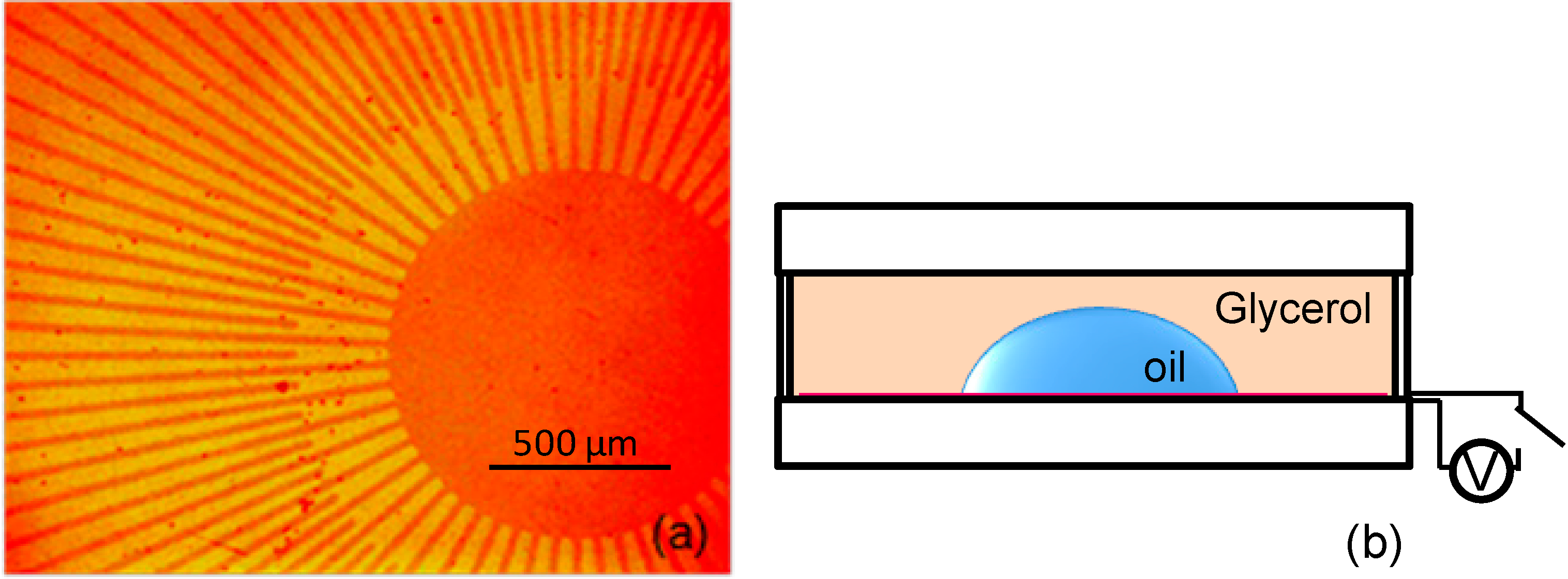
The refractive index of the oil droplet (
n1 ~ 1.67) is larger than that of the surrounding glycerol (
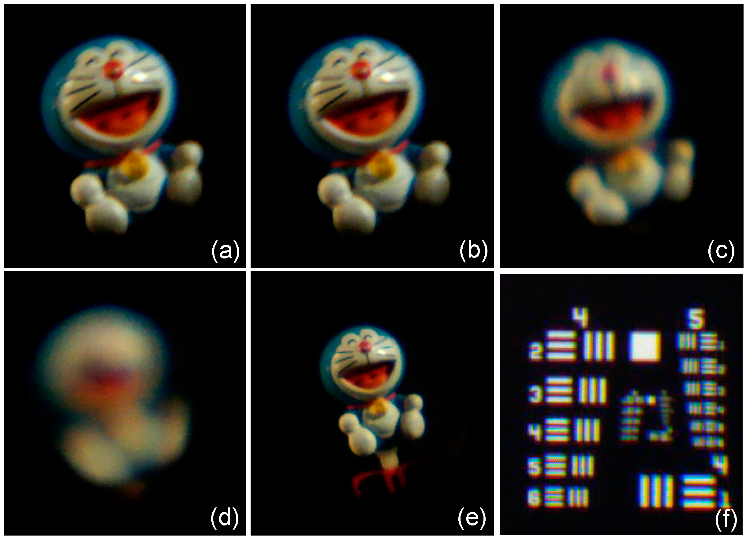
n2 ~ 1.47), so the liquid lens is a converging lens. To characterize the performance of the lens, we observe the image of an object through the lens when it is actuated by a voltage. A Doraemon toy is chosen as the object. The object is placed under the lens cell at ~13 cm. A digital camera is placed above the lens cell to record the image. In the relaxed state (
V = 0), a clear image is observed in white light, as shown in
Figure 3a. The image is inverted in contrast to the position of the object. To actuate the liquid lens, a voltage (500 Hz) is applied to the electrode. When the voltage exceeds
V = 18
Vrms, the image becomes slightly blurry, as shown in
Figure 3b. This voltage is the threshold voltage of the liquid lens. The blurry image implies that the focal length of the liquid lens is changed. The focal length of the liquid lens is expressed by:
where
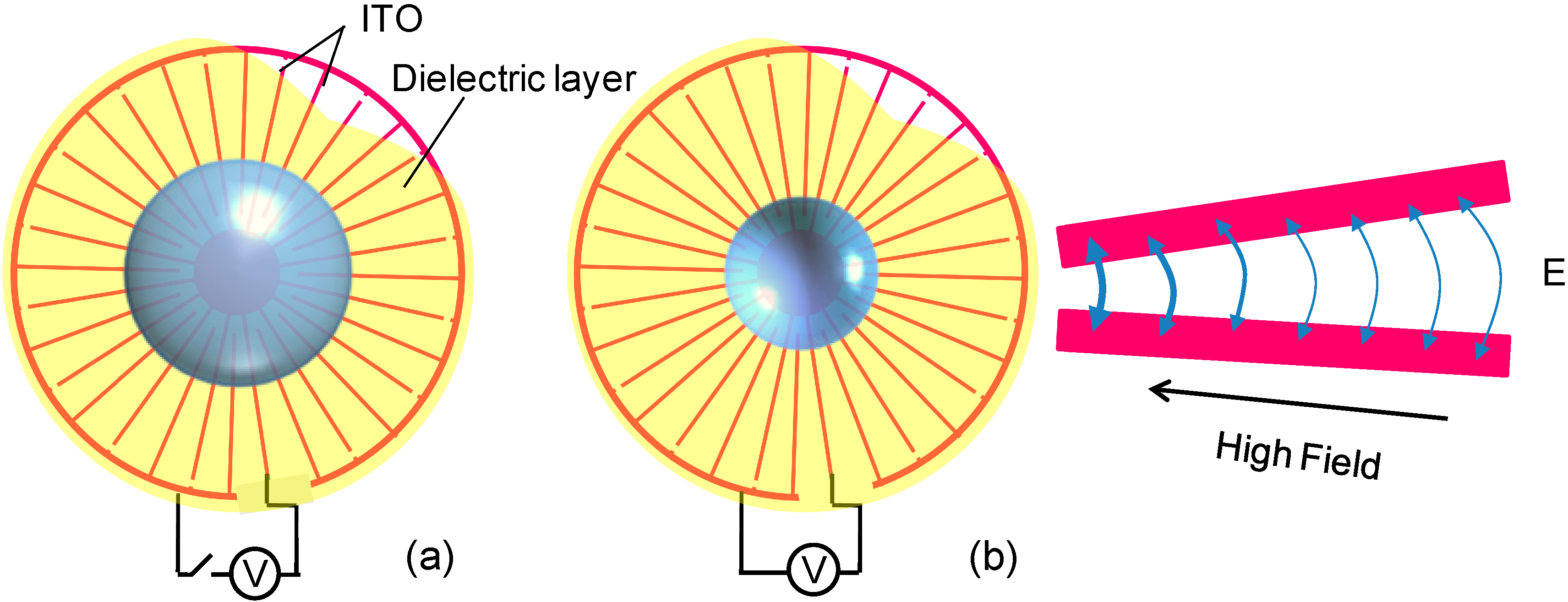
r is the radius of the droplet curvature. According to
Figure 1b, the radius
r of the droplet curvature is decreased when the droplet is actuated. As a result, its focal length
f is reduced.
Figure 3.
Image of a toy observed through the liquid lens at various voltages. (a) V = 0, (b) V = 18 Vrms, (c) V = 30 Vrms, (d) V = 45 Vrms, and (e) refocus at V = 45 Vrms, (f) image of resolution target at V = 0.
Figure 3.
Image of a toy observed through the liquid lens at various voltages. (a) V = 0, (b) V = 18 Vrms, (c) V = 30 Vrms, (d) V = 45 Vrms, and (e) refocus at V = 45 Vrms, (f) image of resolution target at V = 0.
When the voltage is increased gradually, the image becomes much more blurry.
Figure 3c,d show the images when
V = 30
Vrms and 45
Vrms, respectively. When
V = 45
Vrms, the image is highly blurry and could not be recognized completely due to the large defocus. To get a clear image at
V = 45
Vrms, the lens cell is shifted toward the camera. A refocused image with reduced size is observed, as shown in
Figure 3e. To estimate the resolution of the lens, a resolution target is used to replace the toy. In the relaxed state, our eye can distinguish group 5 and element 3 of the target. The corresponding resolution of the lens is ~40 lp/mm. To record the image with a CCD, a glass lens is used in order to sufficiently magnify the image. The image of the resolution target is shown in
Figure 3f. It could resolve group 5 and element 2, and the corresponding resolution is ~36 lp/mm. Due to the aberration of the added glass lens, the observed resolution degrades slightly.
Suppose the lens has no aberration, so the resolution of the lens is limited by diffraction. The limiting resolution can be expressed by [
24,
25]:
where
d is the diameter of the lens aperture,
s is the distance of the object, and λ is the wavelength of light. For
s = 13 cm, λ = 0.5 μm, and the diameter of the lens aperture
d ~ 2.3 mm, the diffraction-limited resolution is calculated to be ~44 lp/mm. As a comparison, the observed resolution (~40 lp/mm) by an eye is lower than that of the diffraction-limited resolution due to the lens aberration. Since this resolution is close to the diffraction-limited resolution, the diffraction limit plays the main role rather than the spherical aberration. When the diameter of the lens
d is decreased, the shape of the droplet becomes contracted. To get a clear image, the object distance
s should be decreased. As a result, the observed resolution is insensitive to the shape change of the liquid lens.
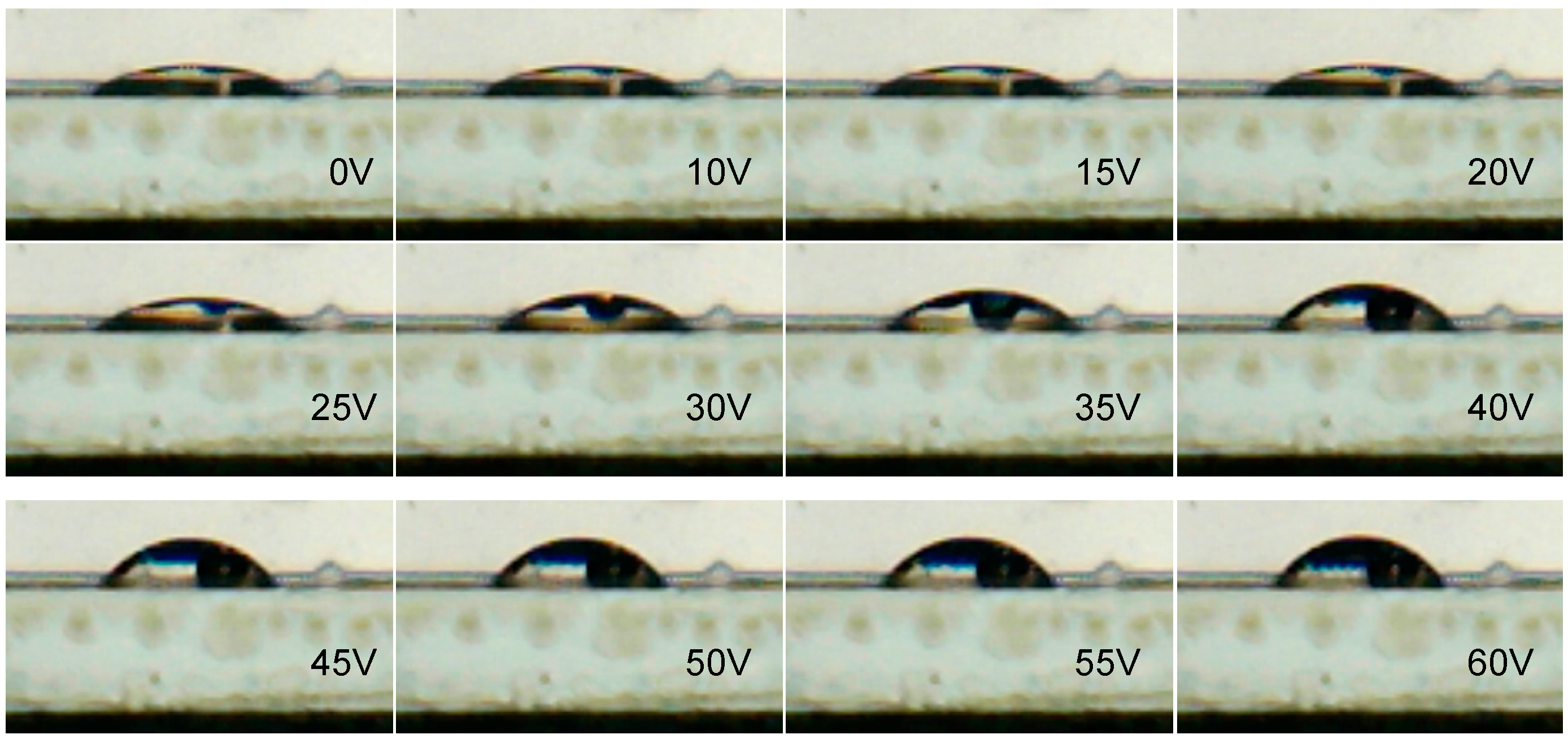
Due to the low surface tension, the droplet has a contact angle on the Teflon surface. The contact angle θ is defined geometrically as the angle formed by the droplet at the three-phase boundary where the droplet, the glycerol, and the Teflon layer intersect. When the droplet is reshaped by a voltage, its contact angle is changed. To measure the voltage-dependent contact angle, one simple method is to monitor the shape of liquid droplet. The digital camera is used to record the side-view surface profile of the droplet. The voltage-dependent shape change of the droplet is shown in
Figure 4. In relaxed state, the radius of the droplet curvature is the largest. When a voltage applied to the electrode exceeds 18
Vrms, the shape of the droplet begins to change. As the voltage increases gradually, the droplet bulges more and more. When the voltage is higher than 45
Vrms, the shape of the droplet does not change obviously. The liquid lens driven with a relatively low voltage is mainly due to two factors: (1) the gap of adjacent stripes is linearly decreased and (2) the voltage is increased. The two factors can largely increase the fringing field or the generated dielectric force, causing the liquid droplet to be deformed effectively. To visually observe the shape change of the droplet, a gated square-wave of 45
Vrms pulse is applied to the electrode. A dynamic video (Media 1) is recorded as given in
Figure 4. The shape change of the droplet is relatively fast.
Figure 4.
Voltage-dependent shape change of the liquid droplet. A dynamic video showing the shape change of the droplet is given at V = 45 Vrms.
Figure 4.
Voltage-dependent shape change of the liquid droplet. A dynamic video showing the shape change of the droplet is given at V = 45 Vrms.
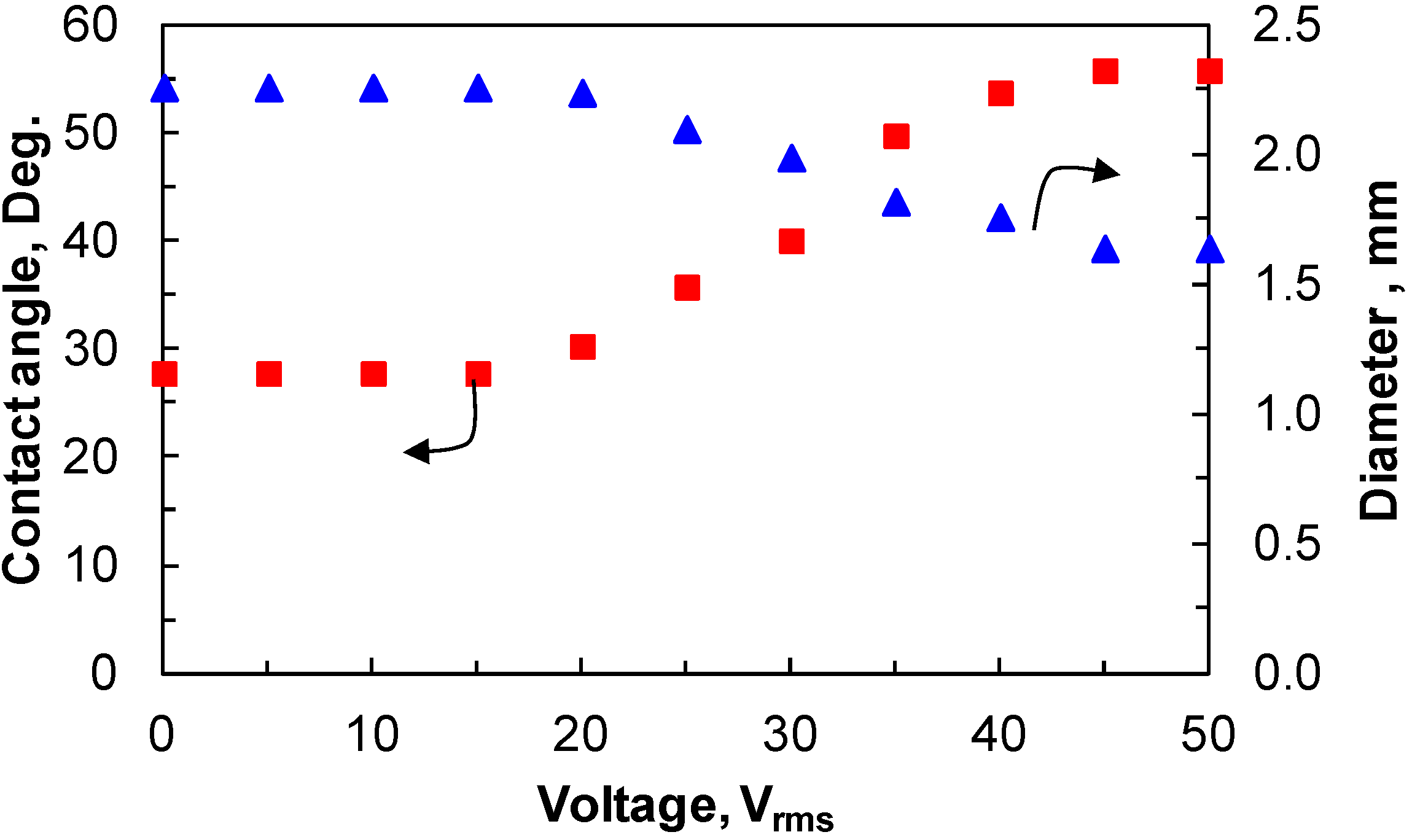
According to the shape change of the droplet shown in
Figure 4, the contact angle θ of the droplet and the diameter of the droplet aperture at various voltages are measured. The results are given in
Figure 5. When
V = 0, θ is measured to be ~27.8°. The contact angle varies from 27.8° to 55.8° when the voltage changes from 0 to 45
Vrms. When the voltage exceeds 45
Vrms, the contact angle increases slightly. When contact angle increases, the diameter of the droplet aperture decreases due to the fixed volume. The diameter varies from ~2.3 to ~1.7 mm when the voltage changes from 0 to 50
Vrms.
Figure 5.
The contact angle and the diameter of the droplet aperture changed with voltages.
Figure 5.
The contact angle and the diameter of the droplet aperture changed with voltages.
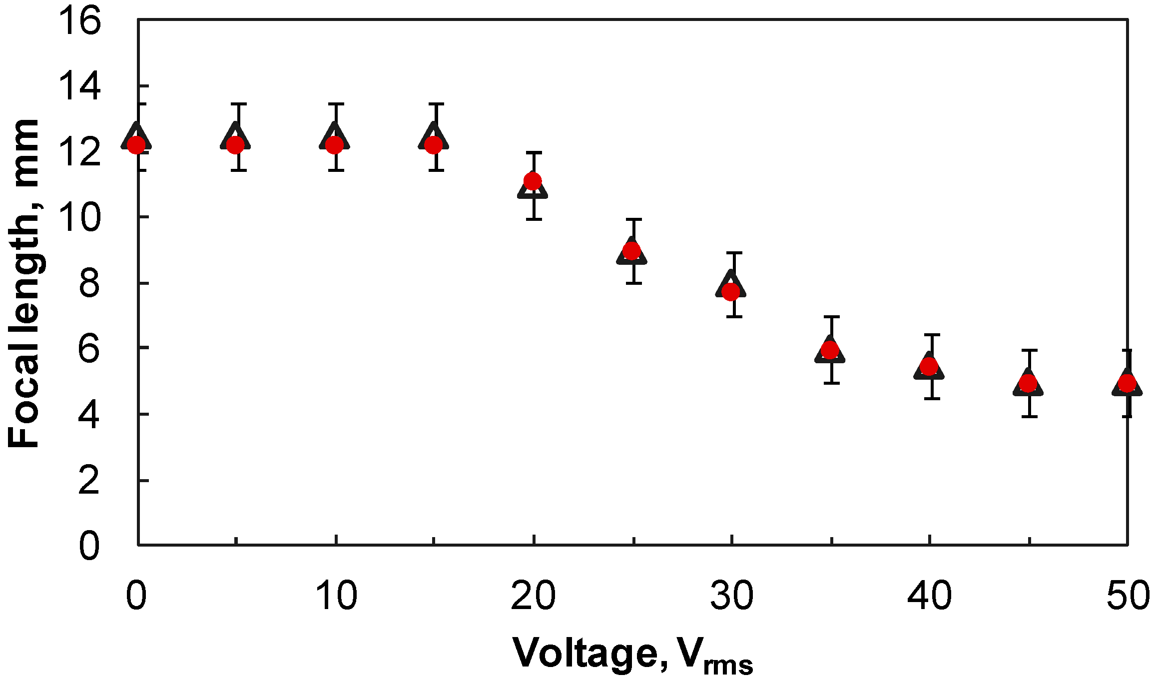
To measure the focal length of the liquid lens, a collimated He-Ne laser beam (λ ~ 633 nm) is used to illuminate the liquid lens. The beam passing through the lens is focused at a spot. The distance from the focal spot to the lens is the focal length.
Figure 6 shows the focal length changed with different voltages (triangles). Due to the thin waist of the laser beam, it is difficult to precisely locate the focal point. As a result, error bars are given.
Using the measured contact angle (
Figure 4), it is convenient to theoretically calculate the focal length of the liquid lens as well. The relationship of the contact angle and the focal length of the lens can be expressed by [
3]:
where
V is the volume of the droplet. From Equation (4), changing the contact angle θ will vary the focal length
f of the liquid lens or vice versa.
The calculated focal length is also given in
Figure 6 (dots). When the voltage changes from 0 to 50
Vrms, the focal length varies from ~12 to ~5 mm. The calculated focal length and the measured focal length overlap well in the range of error bars.
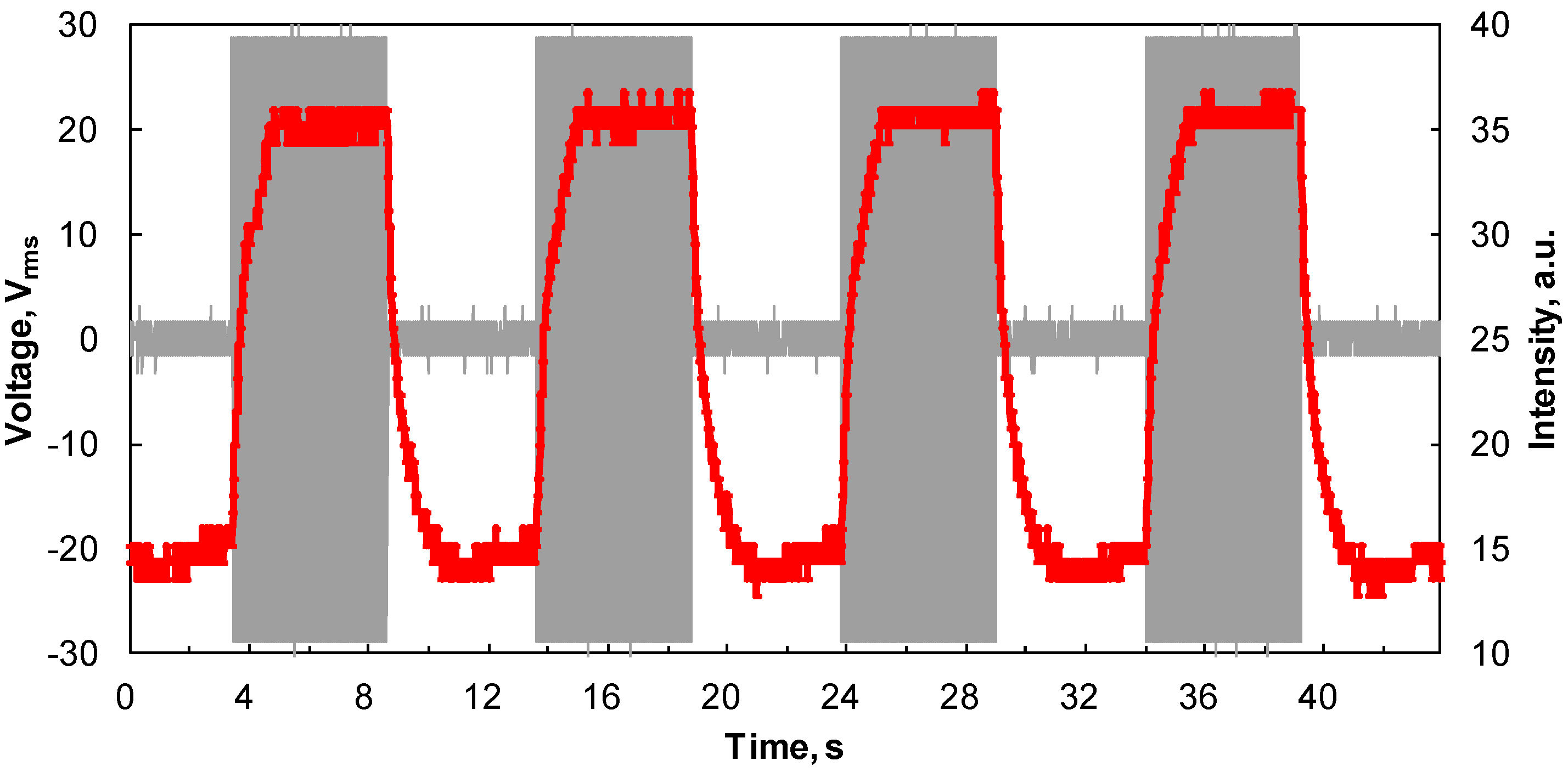
For dynamic actuation, the response time of the liquid lens is measured as well. To measure the response time, a He-Ne laser beam is used to illuminate the liquid lens. A photodiode detector is placed behind the lens cell to receive the laser beam. In the relaxed state, part of the beam is received by the detector when it is placed in a defocusing position. A digital oscilloscope is connected to the detector. The beam intensity change with time is analyzed by the oscilloscope. When a voltage is applied to the lens cell, the beam is focused at the position of the detector, and more light is received by the detector.
Figure 7 shows the time dependent light intensity when a gated square-wave of 28
Vrms pulse is applied to the cell. The duration time is 5 s. It takes ~1 s for the droplet to reshape to a stable state and ~1.5 s for the reshaped droplet to recover to its original state. The driving cycle with four periods shows that the liquid lens has good mechanical stability. For one driving cycle, the power consumption of the lens is about hundred micro-watts.
Figure 6.
The measured focal length (triangles) and the calculated focal length (dots) of the liquid lens changed with voltages.
Figure 6.
The measured focal length (triangles) and the calculated focal length (dots) of the liquid lens changed with voltages.
Figure 7.
Dynamic response of the liquid lens impacted by voltage pulses.
Figure 7.
Dynamic response of the liquid lens impacted by voltage pulses.
Like previous liquid lenses, the size of the liquid droplet is insensitive to the driving voltage because of the fringing field actuation on one side of the substrate. Therefore, the size of the liquid lens is scalable. The driving voltage can be further reduced by increasing the number of ITO stripes. The densities of the two liquids match well, so the gravity effect is negligible when the lens cell is placed in a vertical direction. The liquid lens is also mechanically stable with no shocking or vibrating effects. The droplet can be fixed on the Teflon surface due to the adhesive force. Since the radial-interdigitated electrode provides a circularly-symmetrical electric field, the droplet can be uniformly reshaped without distortion. Due to this reason, our lens can present high resolution (~40 lp/mm) during the focus change. Owing to the radial-interdigitated electrode, the generated dielectric force can effectively reshape the liquid droplet. This is the reason why our liquid lens needs a relatively low driving voltage (<45 Vrms) for a large dynamic range. The response time is reasonably fast when a limited focus change is required.

