1. Introduction
The achieving of autonomy is very important for disabled people, as it means improving the quality of their lives. Ambient assistive living, environmental control systems and supporting devices like the assistive robot FRIEND (
Functional
Robot arm with user-fr
IENdly interface for
Disabled people) [
1] are designed to restore the autonomy of disabled users in All Day Living (ADL) scenarios and in professional life. To ensure economic feasibility, the support systems have to provide user independence from care personal for several hours. The user needs then complete control over the Human Machine Interface (HMI), which itself depends completely on the remaining mental and physical capabilities of the user. Additionally, a gradual or sudden change in motion capabilities may happen depending on the disability. HMI concepts that are helpful at a specific point in time, like systems that use head motion capabilities, may later become insufficient. That holds, e.g., for patients with muscular dystrophy, multiple sclerosis or amyotrophic lateral sclerosis (ALS) where motion based communication capabilities may decrease over time. Steady-state Visual Evoked Potential Brain Computer Interfaces (SSVEP-BCI) and Motion imagination Event-related (de)-synchronization (ERD/ERS) BCI are then becoming important.
Depending on the disability of the user, many HMI methods to issue commands are possible [
2], however all have some disadvantages. Often BCI is mentioned as a specific HMI for a large class of disabled users, esp. for users with very limited motion capabilities. The feasibility of an SSVEP-BCI to control FRIEND has been shown in [
3] and was demonstrated also on several exhibitions and conferences (CEBIT Hannover 2008, RehaCare Duesseldorf 2008, ICORR 2007).
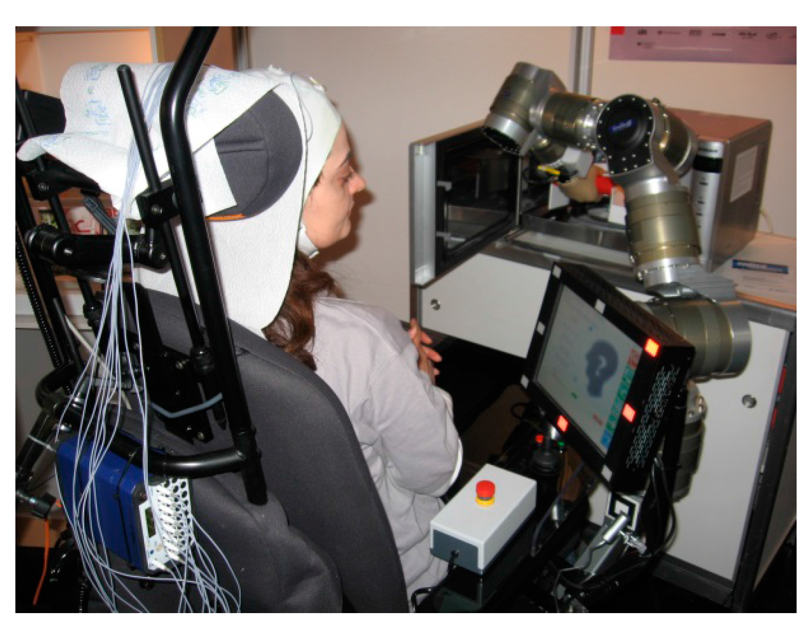
Figure 1 shows control of FRIEND with a SSVEP-BCI in an All Day Living laboratory experiment (ADL) [
2]. The control of different assistive devices like an internet radio, the assistive robot FRIEND, and other environmental systems serve here as use cases for BCI application. However, BCI use is time consuming and has an error rate that cannot be neglected, which is the reason to design a new hybrid BCI and research its capabilities.
Figure 1.
Control of FRIEND with a SSVEP-BCI in an ADL-test bed. SSVEP Diodes are located at the frame of the screen.
Figure 1.
Control of FRIEND with a SSVEP-BCI in an ADL-test bed. SSVEP Diodes are located at the frame of the screen.
To simplify preparation, improve the comfort of the user, extend the user group, and enable research for optimized HMI, a new electroencephalography (EEG)-cap was designed and integrated with an SSVEP-BCI, an ERD/ERS-BCI, an eye-tracker, and an environmental camera. The integration of signal processing for both BCI methods with image processing for an eye tracker and environmental camera in one software package is also accomplished and improves software development capabilities in research and future application of sBCI.
In a first setup, we tested the control of an internet radio, a microwave, and a fridge with six healthy participants. Signal processing for the BCI signals is carried out with a Bremen-BCI software package, which was described [
4,
5,
6] including results of European Project BRAIN [
7]. In this paper, we are reporting first test results. The BCI tests aim mainly on feasibility of the sBCI concept and on a comparison with BCI results which we achieved with a standard EEG cap.
We focus here on the sequential use of the sBCI components whereby the eye tracker or the ERD/ERS-BCI acts as a selector for systems in the environment and the SSVEP-BCI enables the control of the selected device. Five subjects used the eye tracker and one subject who was trained in ERD/ERS–BCI used that one for selection. In both cases, the SSVEP-BCI facilitated the control of the selected device. All participants succeeded in performing five requested tasks with a good performance: the subjects who used eye tracker spent 3.9 s on average on the selection of the target device; however, 20 s on average were needed with ERD/ERS-BCI; a peak information transfer rate (ITR) of 73.9 bit/min was achieved with the SSVEP-BCI; a mean ITR of 41.2 bit/min and an accuracy of 96.3%.
The paper is organized as follows: In
Section 2, we consider two use cases for BCI—control of home appliances and control of an Internet radio.
Section 3 discusses the state of art in EEG-based BCI. In
Section 4, we discuss the layout of the sBCI system and design decisions.
Section 5 describes the user interface and control methods chosen so far.
Section 6 gives details about the subjects, the data acquisition and the results. The paper closes in
Section 7 with a discussion of the results and the lessons learned.
2. Use Cases and General Design Decisions for sBCI
The use cases are inspired by the support of users with tetraplegia in an ADL scenario. Simple devices like a fridge or microwave and more complex ones like an internet radio have to be operated. Typically, the user has to select a device and then issue commands to the selected device. For a fulfillment rate of the initialized tasks larger than 80%, the user has to support the automation system. The user can interrupt it if a problem in task execution arises and issue corrective commands. After the problem is solved, control is handed back to the automation system.
2.1. Use Case 1: Control of Simple Home Appliances
Here we consider an ADL scenario. The user sits in a wheelchair with a robot arm and would like to drink. The user may first select the fridge and then send an “open” command to the actuator that opens the door of the fridge.
Once the door is open, the user chooses the robot arm and issues a high level command “grasp bottle”. The robot arm which is mounted on the wheelchair performs an autonomous picking up of the object in the fridge. The control of the robot arm is realized as a combination of vision-based object recognition and advanced path planning as described in [
1].
2.2. Use Case 2: Operation of Complex Devices
For a device like an internet radio, a sequence of inputs and commands has to be generated to start a specific task. It may also be necessary to intervene in task execution to support the automation algorithms. Typical commands after choosing the internet radio are: (a) turn radio on/off; (b) select channel; (c) set volume up/down; (d) operate playback functions (pause, resume fast forward/backward etc.). The user has to select the HMI and then issue one or more commands.
2.3. General Design Requirements
General requirements for a BCI that is used by a disabled user as an HMI are: (a) preparation of the user should be possible within 5 min, (b) wearing comfort has to allow uninterrupted usage for several hours, (c) the user must be able to switch the system or components on and off without external support.
3. State of Art for EEG-Based BCI
The BCI system establishes a direct communication channel between the human brain and a control or communication device. BCIs detect the human intention from various electrophysiological signal components, such as steady-state visual evoked potentials (SSVEPs) [
8,
9], P300 potentials [
10] and sensorimotor rhythms (SMR) and translate it into commands. The brain signals are recorded from the scalp using electroencephalography (EEG). The movement-related modulation of mu (7–13 Hz) and beta (13–30 Hz) sensorimotor rhythm induced by the imagination of limb movements [
11,
12] has gained considerable interest as a more natural paradigm for the non-invasive BCIs. Compared to those BCIs based on evoked potentials such as SSVEP and P300, motor imagery BCIs do not need external stimulation. SMR modulation patterns in the form of event-related de-synchronization (ERD) and event-related synchronization (ERS) are independent in terms of any stimulation and allow the user to freely decide when they wish to generate a control signal. Nevertheless, ERD/ERS-BCIs are generally even more demanding in the usage and more complex in the implementation. ERD/ERS-BCIs require extensive user training and adaptive signal processing algorithms tailored to the mental states (fatigue, workload and emotion) and learning rates of each subject [
13,
14], although advanced signal processing methods and well-designed training interfaces are used in BCI research. However, the output of the ERD/ERS-based BCI systems is still less reliable and the interaction speed is much lower in comparison to other paradigms and still far away from mainstream interaction modalities such as joysticks or mice. Currently, the SSVEP approach provides the fastest and most reliable paradigm for non-invasive BCI system implementation and requires little or no training. Steady-state visual evoked potentials are brain responses elicited by presenting repetitive visual stimulation above 5 Hz. Exposing the user to flickering lights in frequencies between 5 and 20 Hz evokes SSVEPs with comparatively large amplitude [
15] but it is inconvenient and tiring for the user. Moreover, during the non-control state (NC state), when the user does not want to generate any command, the continuing flickering could induce false positive classifications if the BCI system mistakenly declares the NC state as an intentional control state.
As explained in the next chapter, the requirements for control of complex devices lead to the development of a BCI with hybrid architecture (hBCI). A hybrid BCI (hBCI) is usually defined as a BCI combined with at least one other interface system or device. Such a system or device might be a BCI channel relying on other brain patterns, the output of an external assistive device (chin-joystick, switch,
etc.) or other bio signals (heart rate, eye gaze, muscular activities,
etc.) [
16]. Recently multimodal interfaces have demonstrated promising results towards more reliability, flexibility and faster interaction. Some of them are based on multiple brain signals [
17,
18,
19,
20,
21]. Others combine brain and additional bio signals [
22,
23]. A multimodal interface including eye tracking to determine the object of interest and a brain-computer interface to simulate the mouse click is presented in [
24,
25]. Eye movements are detected with a remote eye tracker that is mounted opposite of the user and uses an infrared camera to observe gaze direction. A limitation of such a remote system is that it can only be used with screen-based interfaces.
A further important issue in non-invasive BCI research is to make the EEG acquisition system more comfortable and suitable for daily use. Basically, two trends of development can be identified for this design aspect. Firstly, minimizing the number of electrodes in order to reduce hassle and setup time and, secondly, the development of dry [
26,
27,
28] or water-based electrodes [
29]. Several commercial non-medical EEG headsets following these trends have been released over the last few years. The commercially available BCI headsets promise ease of use, low cost, short setup time, as well as mobility. The headsets are wireless and vary in the number of electrodes: NeuroSky’s MindSet and MindWave (
http://www.neurosky.com) use a single EEG electrode positioned on the user’s forehead; ENOBIO [
30] provides four channels of bioelectric signals; Emotiv’s EPOC headset [
31] measures electrophysiological signals using 14 saline non-dry sensors placed over the user’s head. However, the data acquired by such consumer devices contains neither event related potentials nor sensorimotor rhythms. These commercial-graded systems focus on gaming, entertainment, and biofeedback training based on the attention level and meditation. Based on this state of art analysis, the system layout and design decisions are discussed in the next chapter.
4. System Layout and Design Decisions
The capacity of EEG based BCIs must be carefully reflected in order to integrate a BCI with the ambient intelligence environment and control strategy of assistive systems for a disabled user. A detailed analysis of the support tasks carried out for FRIEND and other devices in the environment of the disabled user lead to the following principal actions that had to be carried out with a BCI:
Start and stop the BCI completely or only a specific BCI mode;
Selection of a specific support device (e.g., robot, gripper, microwave, fridge or radio);
Selection of a specific action of the selected device (e.g., open fridge, grasp bottle, open/close gripper, chose moving direction of robot arm, move arm a specific distance in chosen direction);
Switch to the HMI screen;
Navigate within the HMI screen (left, right, up, down);
Start a specific action;
Stop a running action.
In this paper, a new EEG head cap for BCI in combination with an eye tracking system is introduced. We will mainly focus on the sequential hybrid BCI, where the eye tracker or ERD/ERS-BCI acts as a selector and the SSVEP-BCI generates the control commands.
The sBCI system includes a lightweight, ergonomically designed headset which integrates multi-channel EEG equipment, an eye tracker system with environmental observation and an integrated visual stimulator for SSVEP-BCI. The full integration of the SSVEP stimulator, SSVEP electronic and BCI software with the eye tracker was the main reason to design an eye tracker instead of using a commercially available one. An EEG amplifier Porti 32 (Twente Medical Systems International, Oldenzaal, The Netherlands) connected to a standard notebook is used to measure the brain activity, while an LED pattern generator produces flicker frequencies. A programmable remote controller sends the control commands to the controlled devices. The universal structure of the sBCI interface allows the easy integration of additional devices and further functionalities into one common graphical user interface. The following sections describe the system layout and design criteria.
4.1. Gaze-Controlled Interface
An overview about eye tracking technology can be found in [
32]. The sBCI system described here is from a Video-Occulography (VOG) type. It uses a mobile head mounted eye tracker, which is specifically developed for use with the BCI-headset and SSVEP-BCI. Wearable eye trackers which were available on the market did not allow a seamless integration into the sBCI multimodal headset. The provided software is also not open source and the integration into a single hybrid system is rather difficult, especially if additional information (e.g., the pupil diameter) is required. The sBCI eye tracking system detects the user’s intention to interact with a specific device in its environment. For this, three cameras are used. Two cameras are for tracking of left and right eye, the remaining one is for monitoring the environment.
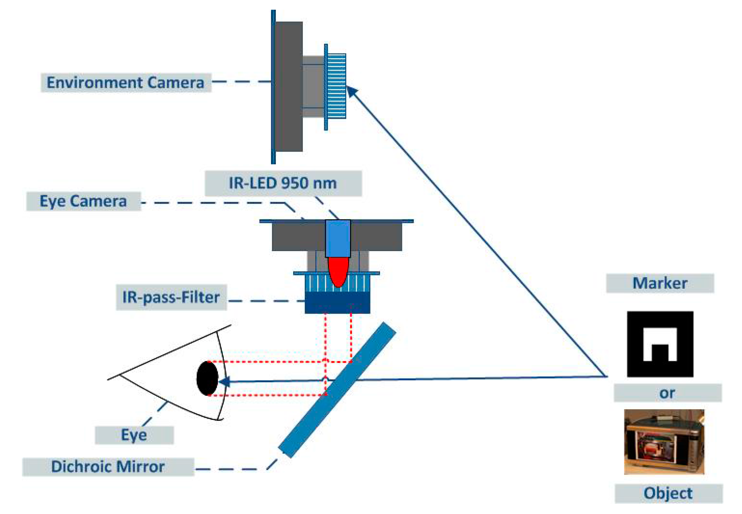
Figure 2 shows the principal layout, with one of the eye cameras and the environmental camera of the tracking system DeLock USB CMOS Cameras 95,852, 1.3 Megapixel are used in all cases. The resolution of the DeLock cameras is set to 1280 × 1024 pixels for environmental images and to 640 × 480 pixels for eye tracking. The user’s eyes are illuminated by Infrared (IR)-LEDs (LD271, OSRAM Opto Semiconductors GmbH, Regensburg, Germany)
Pmax = 2.7 mW) through a dichroic mirror (Edmund Optics NT62-630, Barrington, NJ, USA).
The eye cameras are mounted in parallel to the IR-LEDs and have modified lenses without the mandatory IR blocking filter. Instead, two IR pass filters (LUXACRYL-IR 1698) in front of the lenses suppress most of the visible environmental light. The light of the IR-LEDs in combination with the two infrared filters in front of the eye cameras give a stable illumination of the eyes. This significantly eases the process of detecting the pupils and estimating the gaze direction.
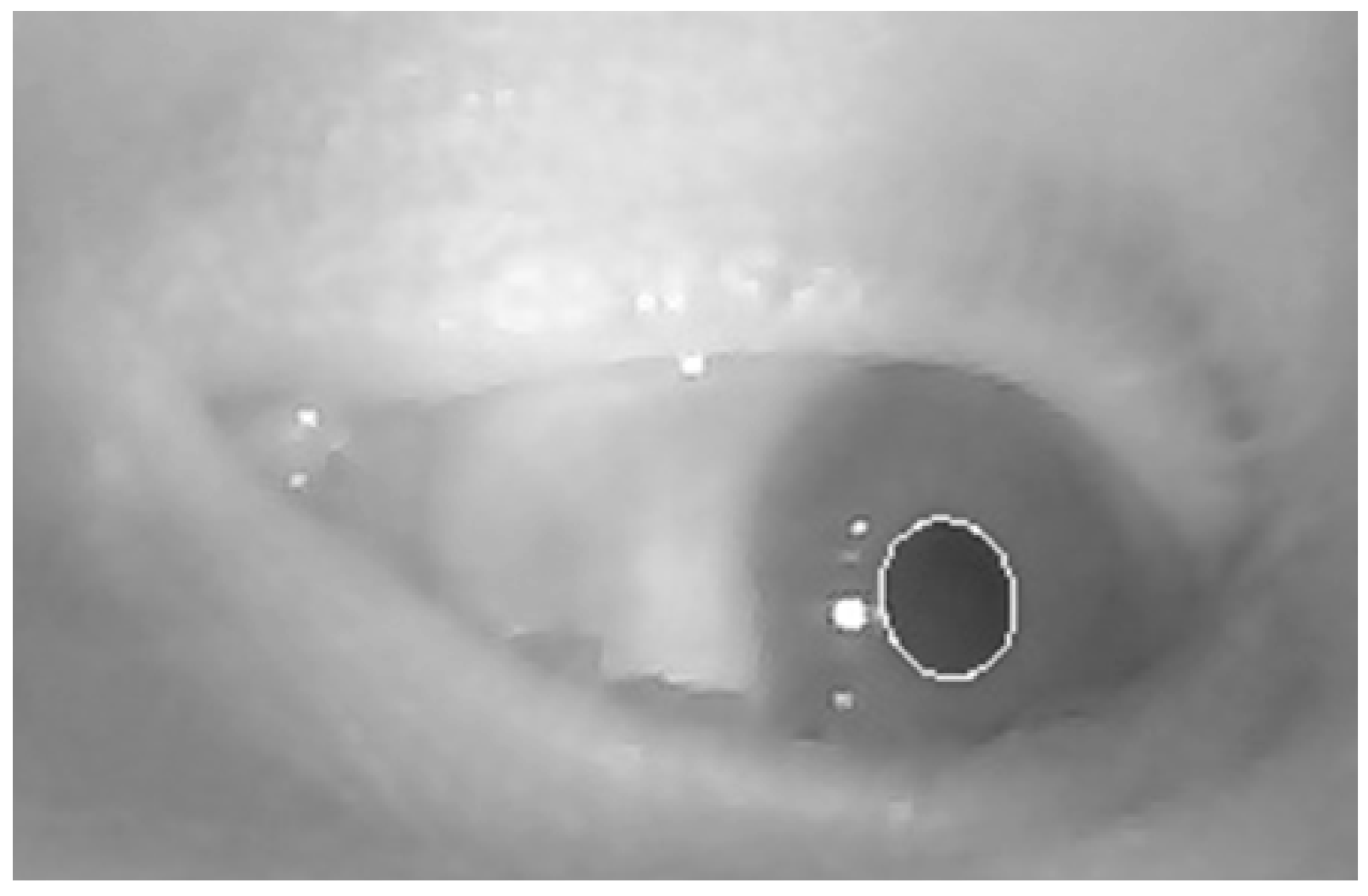
Figure 3 shows the characteristic image of an eye camera and the result of pupil recognition.
The dichroic mirrors allow mounting the eye cameras outside the user’s field of vision. It reflects the IR light coming from the LEDs into the user’s eyes and back into the eye cameras while being fully transparent for visible light. Additionally, the mirror holders can be used for the SSVEP stimuli LEDs. Based on the estimation of the gaze direction, the object of interest is determined. The object recognition may follow different approaches. The object may be recognized in the image of the environmental camera by using specific colors that are not immediately recognizable as marker, by using SIFT (Scale Invariant Feature Transform) or a comparable algorithm to recognize known objects or by specific markers, e.g., chosen from ARToolKit [
33].
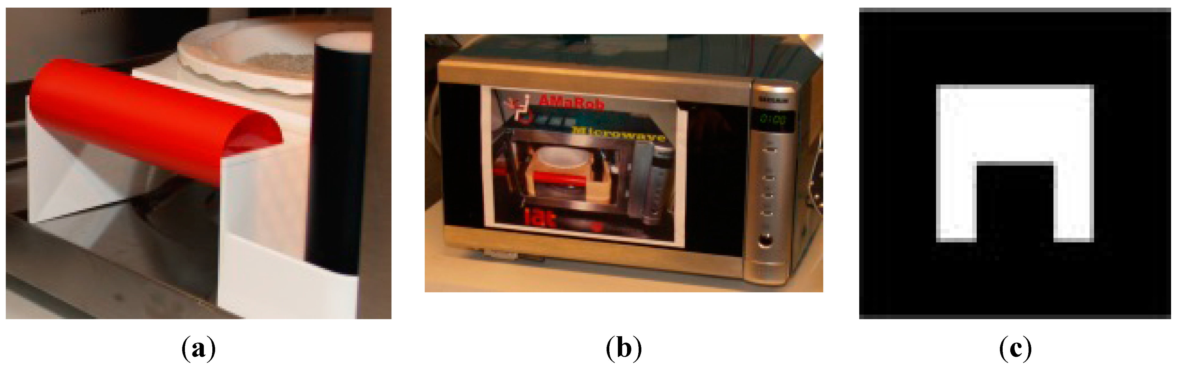
Figure 4 shows typical markers of the different categories. Based on the estimation of the gaze direction the object of interest is determined.
Figure 2.
Layout of eye tracker and environmental camera to recognize gaze direction and objects to be controlled.
Figure 2.
Layout of eye tracker and environmental camera to recognize gaze direction and objects to be controlled.
Figure 3.
Eye and pupil detection (large white circle) shown in eye camera image.
Figure 3.
Eye and pupil detection (large white circle) shown in eye camera image.
Figure 4.
Marker layout used to distinguish between home devices, object with specific color and size as marker (a), object to be recognized by SIFT (b) and artificial ARToolKit marker (c).
Figure 4.
Marker layout used to distinguish between home devices, object with specific color and size as marker (a), object to be recognized by SIFT (b) and artificial ARToolKit marker (c).
Although very powerful SIFT algorithms have been developed for object recognition [
34,
35] the recognition approach in this paper is based on specific ARToolkit markers which are detected in the live video stream [
36]. This decision was made to decouple sBCI and SIFT related research projects and to be able to show the feasibility of BCI usage in complex control tasks without image processing overhead. The ARToolKit allows extracting the 3D position of the marker in the world coordinate system while knowing the exact marker dimensions.
To determine the gaze direction, it is necessary to extract the pupil centers from both eye camera images. The following standard image processing methods are used:
Calculating the histogram;
Finding first distinctive maximum;
Threshold the image based on that maximum;
Erode and dilate the image with a circle element;
Use edge detection and calculate best fitting ellipse (regarding its roundness and size).
Before using the eye tracker system, a calibration is required. The eye tracker calibration specifies the relationship between both eye cameras and the scene camera. Each subject is instructed to fixate upon a calibration marker shown in front of him/her for a short time while changing the head position and the viewing angle. Simultaneously, the eye tracker records the pupil centers and marker coordinates for each fixation. The marker coordinates and the pupil centers are grouped into a constraint matrix that is used to compute a transformation matrix via singular value decomposition. After calibration, this matrix can be used to transform the pupil centers to gaze coordinates relative to the scene image. The gaze coordinates are then used to determine the object in the environment where the user is concentrating on. This object can then be selected as the one to where future input commands are directed.
For the selection procedure, the eye tracker or the ERD/ERS-BCI can be used. A recognized object may be considered to be selected if the user looks at it for more than a predefined fixation interval. To achieve a fast object selection while avoiding unwanted selection actions, the selection interval should be chosen carefully. Best results are achieved with a selection time between 1.5 and 3 s. Usage of ERD/ERS for selection is described in the next section.
4.2. sBCI-Headset
The primary goal of the sBCI newly developed head set was an easily applicable, convenient, wearable, and appealing multi-sensor device, which allows easy data fusion of BCI paradigms with other input modalities like eye tracking. The sBCI, shown in
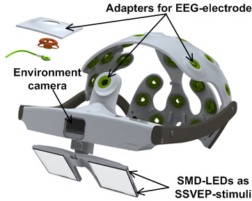
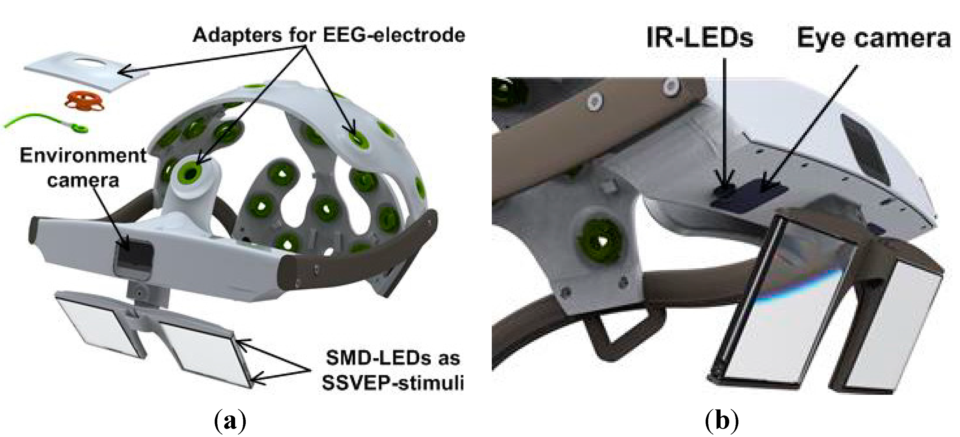
Figure 5, includes a hard case cap with adapters for up to 22 EEG-electrodes, two eye cameras, one camera for environment monitoring, and a miniature SSVEP stimulator with four surface-mounted (SMD) LEDs allowing a 4-way SSVEP interaction.
The EEG-electrodes are placed at the pre-defined positions according to the extended international 10-10 system of EEG measurement. The electrodes which are integrated in the headset are commercially available conventional Ag-AgCl EEG gel electrodes. The electrode assembly with the holder and spiral spring provides many degrees of freedom for good adaptation on the user’s head and also offers the possibility of gel injection and abrading the skin for reducing the impedance. The CAD-models of the headsets are developed with the help of 3D-models of adult heads and manufactured by using a rapid prototyping technology. The sBCI-headset is built in three different sizes based on head circumferences in order to fit the heads to a large number of users.
Figure 5.
sBCI headset which includes a hard case cap with 22 EEG electrode positions (a) two eye cameras, one camera for observation of the environment and four SSVEP-stimuli at the edges of the infrared mirrors (b).
Figure 5.
sBCI headset which includes a hard case cap with 22 EEG electrode positions (a) two eye cameras, one camera for observation of the environment and four SSVEP-stimuli at the edges of the infrared mirrors (b).
4.3. Brain Computer Interface
4.3.1. SSVEP-BCI
Eight EEG electrodes are used to record neural activity from the occipital region of the scalp. The visual stimulation is provided using four LEDs in SMD 0805 size (surface mounted device, 2.0 × 1.25 mm). The flicker frequency and brightness of the LEDs is controlled by a dedicated LED controller. This device uses a PIC18F4550 microcontroller (Microchip, Chandler, AZ, USA) as a communication interface and master timing generator and eight PIC16F690 microcontrollers as independent brightness controllers for up to eight output channels. The flicker frequency is adjustable from 0.2 to 1000 Hz with a timing resolution of 50 μs. The brightness can be set between 0% and 100% with a resolution of 1%. All brightness and timing parameters are controlled by software and can be adjusted at runtime from a host computer via USB interface. The LED controller is configured by software specially written for this purpose which allows easy access to the complete controller functionality. The four stimuli LEDs are placed at the corners of the eye tracker’s dichroic infrared mirrors, as shown in
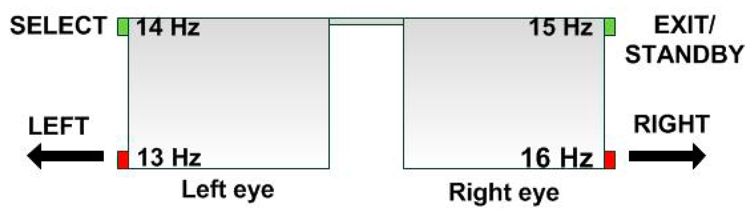
Figure 6. To simply the navigation among LEDs for the user, two different colors are used: green LEDs are placed on the top and red LEDs at the bottom of the mirrors. The LED controller also allows a different assignment of frequencies to the four LED positions. This arrangement of LEDs allows focusing on a stimulus while simultaneously observing the environment and/or the controlled device.
The distance between the lights and the user’s eye is about 3 cm. The chosen stimulation frequencies are: 13 Hz (LED on left-bottom), 14 Hz (LED on left-top), 15 Hz (LED on right-top) and 16 Hz (LED on right-bottom). With the LED controller, it is easy to change frequencies of all LED as well as the on/off intervals in future consideration. The signal processing module uses the Minimum Energy Combination (MEC) for spatial filtering, signal power estimation, and normalization for each stimulation frequency [
4]. The spatial filter re-adjusts the input channels in order to minimize background activity and noise. The next step of signal processing is the estimation of power in each stimulation frequency based on a 2 s data window. Spatial filtering and power estimation is executed every 125 ms. The power values are normalized to convert the absolute values into relative probabilities. The probability in a stimulus frequency has to exceed a predefined threshold in order to be classified. After classification of a nonzero class, an idle period of 2 s is introduced, in which no further classification is made.
Figure 6.
Location of four flickering LEDs at the dichroic infrared mirrors and possible meaning in a specific application.
Figure 6.
Location of four flickering LEDs at the dichroic infrared mirrors and possible meaning in a specific application.
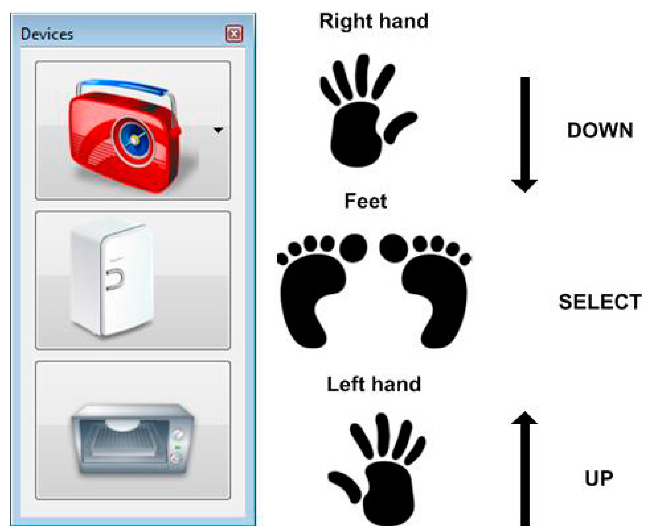
4.3.2. ERD/ERS-BCI
Motion imagination (MI) causes characteristic changes in EEG signals (ERD/ERS) which can be measured as power changes in specific frequency bands. The topography and time course of the changes depend on several factors, including the type of MI, the contents of the imagery, the subject training and experience. Before the ERD/ERS-BCI can be efficiently used, the user has to undergo a calibration procedure performed in a cued paradigm. Three types of motion imagination are used as intentional control (IC) states: left hand (LH), feet (F) and right hand (RH). The data recorded during the calibration session was used to adapt the classifier to the individual user. This is ensured by identification of individual frequency bands for μ and β rhythms, estimation of spatial filters using the Common Spatial Pattern (CSP) algorithm [
37], extraction of features and training of two-stage classifiers. As first, logistic regression classifier is trained to discriminate between non-control (NC) and IC states. If the data represents a potential IC state, it is passed to the second stage classification procedure, which performs the discrimination between three IC states [
7]. In the operational phase, the participants used the asynchronous ERD/ERS-BCI to scroll through the device submenu and select a device of interest. The EEG subject-specific features extracted from the 2 s long sliding window were exploited as inputs to the created classifier. The classifier output, which is updated every 125 ms, is passed on the circular buffer containing the classifier outputs for the last 5 s. The control signal is forwarded to the sBCI interface if six uniform IC classifications were collected. After the execution of each command, an idle period of 2 s is introduced.
5. User Interface and Control Method
In order to consider feasibility of the sBCI system for the control of complex systems, a test bed is designed which contains the HMI for the operation of an internet radio, a fridge and a microwave. The internet radio is used as a complex device while the fridge and microwave are two examples for simple devices which are used together with FRIEND in an ADL scenario. The control of the internet radio with sBCI has a similar complexity as the control of an assistive robot. A robot can be used in a study only after additional safety measures are introduced in order to avoid endangering of the user. Ensuring user safety requires extensive study of failure modes of sBCI and the development of a safety concept [
38]. The safety study would exceed the content of this publication.
The user interface takes the classification from the BCI and gaze commands from the eye tracker as an input and sends commands to the selected devices. Depending on the subject’s abilities and preferences, either the eye tracker or the ERD/ERS-based BCI can be set up to select the target device. The SSVEP-BCI facilitates the control of the selected device.
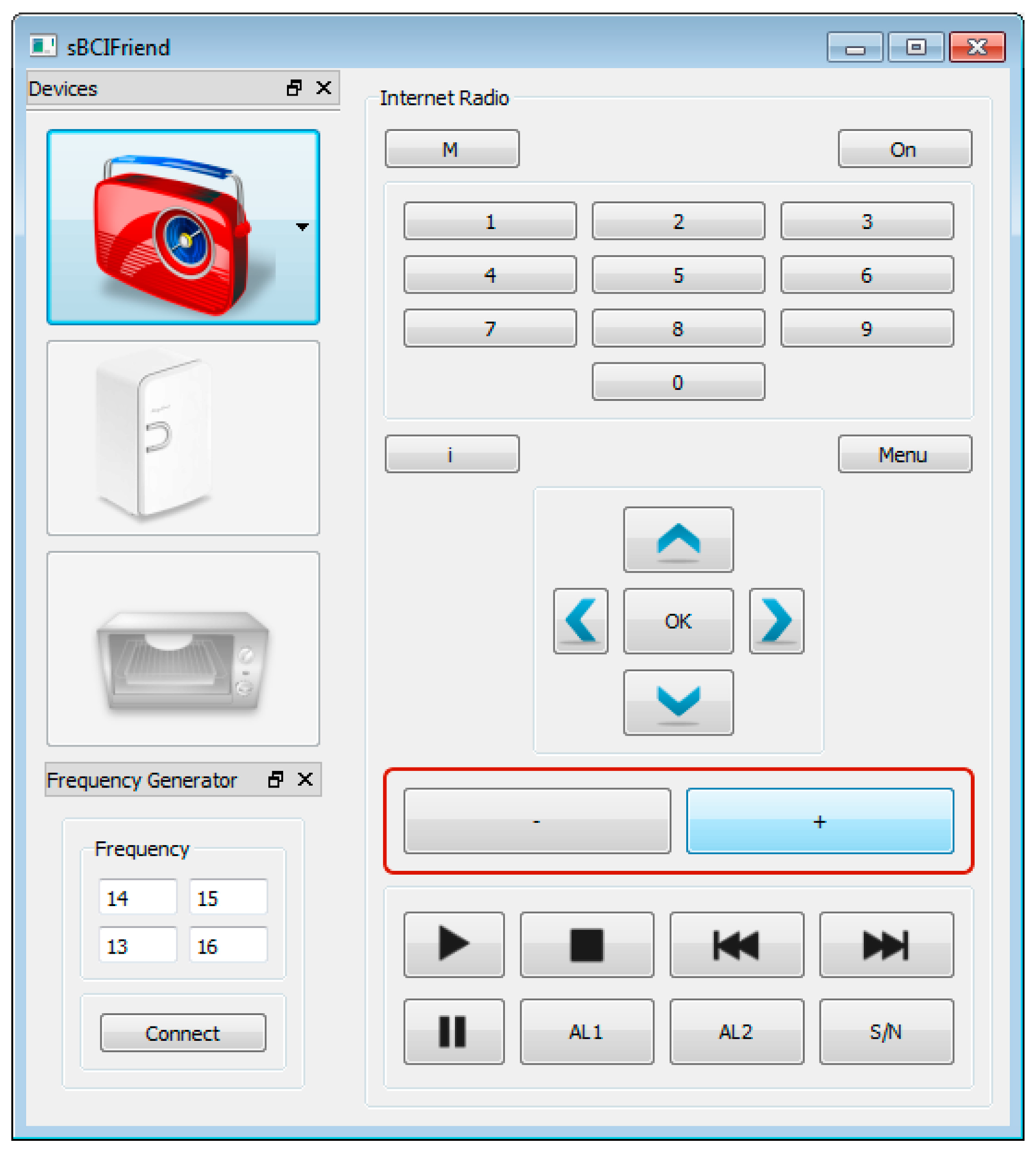
Figure 7 shows the graphical user interface (GUI) for the internet radio. It gives access to the main functionalities and informs the user about the currently selected position inside the hierarchical structure of the interface. sBCI user interface presently contains three external home devices: internet radio (Grundig Cosmopolit 7), fridge and microwave. The interface is similar for all devices and is divided in two parts: The left side allows the device selection while the right side changes dynamically and gives access to the respective functionalities of the chosen device. All icons of this interface originate from
www.iconarchive.com. Each command coming from the BCI or the eye tracker is accompanied by an audible and visual feedback to the user.
The following devices and main functionalities are currently implemented:
Internet radio: On/off, channel selection from 0 to 9, music source selection (internet radio, FM radio, music archive), menu configuration (right, up, left, down, and OK), volume up/down and standard playback functions (pause, resume and end playback, select previous or next track).
Fridge: open and close door.
Microwave: Cooking time selection, start cooking and release door.
Figure 7.
GUI for the internet radio.
Figure 7.
GUI for the internet radio.
5.1. Gaze-SSVEP Interface
The combined control interfaces of the headset allow the user to select a specific device with the eye tracker by simply focusing on it for a predefined selection time. After selection, the device is operated using the SSVEP-BCI. When the user has selected a specific device with the eye tracker, several buttons appear on the GUI showing different functionalities which are related to this device, as shown in
Figure 8. The SSVEP stimuli start flickering and the SSVEP-BCI automatically starts analyzing the EEG signals.
The hierarchical menu structure of the interface implies a two-level control:
Level 1: All functionalities of a specific device are grouped together in sub-menus. This level enables the navigation through the functionalities’ sub-menus (13 and 16 Hz), offering access to the sub-menu actions (14 Hz) and stopping the SSVEP processing and returning to the primary BCI-system by using the standby-command (15 Hz) (see
Table 1). Furthermore, the first level enables the direct access to several sub-menus in order to accelerate navigation.
Level 2: The sub-menu provides the user several buttons related to the different actions. The user can navigate through the available actions (13 and 16 Hz), execute the action by using the select-command (14 Hz), or quit this menu level (go back to level 1) (15 Hz).
To turn down the volume on the radio, the user has to produce the command sequence shown in
Table 2. A two-level menu structure has great advantages, especially for devices with a large number of functionalities, e.g., the internet radio or the microwave or the robot arm. There is no need to have the same menu for the fridge application because only the door can be chosen for a control command. However, to avoid inconsistencies in the user interface, the same hierarchical structure has been applied to all considered devices.
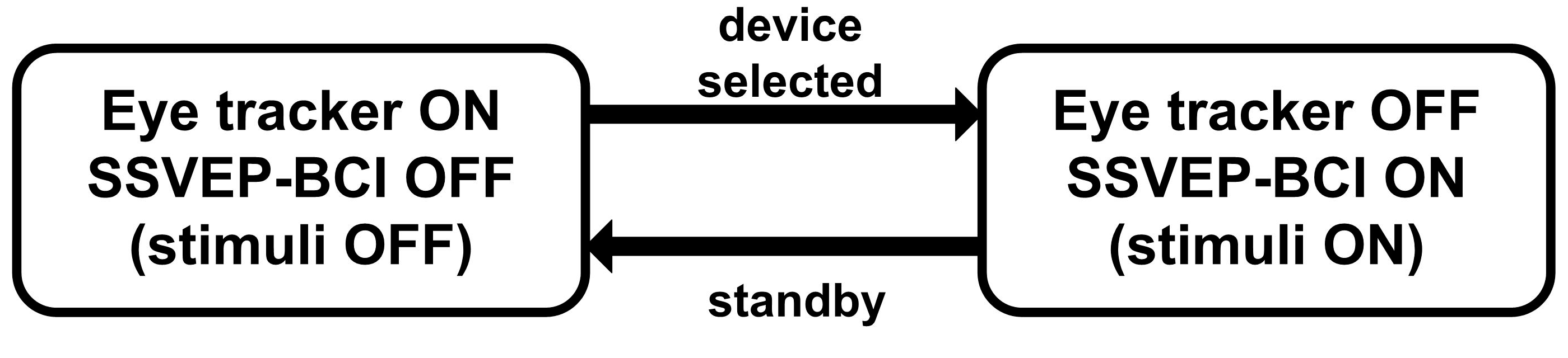
Figure 8.
Hybrid Gaze-SSVEP BCI with sequential processing. The eye tracker acts as a selector which activates the SSVEP system.
Figure 8.
Hybrid Gaze-SSVEP BCI with sequential processing. The eye tracker acts as a selector which activates the SSVEP system.
Table 1.
Quick access to submenus.
Table 1.
Quick access to submenus.
| Device | “Left” (13 Hz) | “Select” (14 Hz) | “Exit/Stand-by” (15 Hz) | “Right” (16 Hz) |
|---|
| Internet radio | Volume | Channel | Mode | Menu |
| Fridge | Door | Door | Door | Door |
| Microwave | Timer | Timer | Operation | Operation |
Table 2.
Turn down the volume on the radio.
Table 2.
Turn down the volume on the radio.
| Number | Frequency | Action | Audit. Feedback | Command |
|---|
| 1 | 13Hz | Volume (level 1) | Volume | - |
| 2 | 14 Hz | Select (level 1) | Increase | - |
| 3 | 13Hz | Left (level 2) | Decrease | - |
| 4 | 14 Hz | Select (level 2) | Select | Turn Down |
| 5 | 15 Hz | Exit (level 2) | Volume | - |
| 6 | 15 Hz | Standby (level 1) | Standby | - |
6. Subject and Data Acquisition and Results
A preliminary evaluation of the sBCI-SSVEP and a comparability test of the sBCI-ERD/ERS system is carried out in order to prove the feasibility of the concept and compare sBCI results with previous ones that use the same software packages. A total of six able-bodied subjects were recruited. All participants used the sBCI-SSVEP system. Five participants (subjects A–E, aged 30.8 ± 7.4; 3 female and 2 male) used the eye tracker system to select a target device. One participant for the comparability test (subject F, 31 years old, female) used the ERD/ERS-BCI as the primary system of the sBCI. Subject F has been trained regularly for 12 months on the ERD/ERS-BCI. She also attended the study published in [
7] but was the only trained subject available at the time of the sBCI study. In all cases the SSVEP based BCI was used to control the selected device. All subjects had normal or corrected to normal vision. According to self-reports, none of the participants had a previous history of neurological and psychiatric diseases that may have influenced the experimental results. The subjects were sitting in a comfortable chair. The markers were placed on physical devices at a distance of about 3 m from the subject. 8 channels (Pz, PO3, PO4, PO7, Oz, PO8, O9, O10) were used for SSVEP detection, and 14 channels (FC3, FCz, FC4, C5, C3, C1, Cz, C2, C4, C6, CP3, CPz,CP4, Pz) covering the sensorimotor area were passed to the ERD/ERS signal processing modules. All channels were grounded to the AFz which was placed on the forehead. The impedance was kept below 5 kΩ. An EEG amplifierPorti32 (Twente Medical Systems International, Oldenzaal, The Netherlands) was used to capture the EEG data. The Porti32amplifier records unipolar inputs, configured as the reference amplifier,
i.e., all channels are amplified against the average of all connected inputs. The signals were high-pass filtered at 0.1 Hz and digitized with a sampling rate of 256 Hz. To reduce power line noise, a 50 Hz notch filter was applied. The hybrid sBCI system was realized using the BCI 2000 general software framework [
39]. The signal processing module implemented the methodology presented in
Sections 4.3.1 and
Sections 4.3.2 using the Matlab interface of BCI2000. The user interface (GUI) and gaze detection software were implemented as external modules in C++. The BCI2000 was configured to stream its output to external modules via UDP (User Datagram Protocol) in real time.
6.1. Experimental Protocol
Each experiment starts with an Eye tracker calibration or an ERD/ERS calibration.
(1) Eye tracker calibration: Eye tracker calibration is required to establish mapping between the eye cameras and the environmental camera for a particular user. During a short fixation interval, the system records the 2D pupil center and the corresponding 3D coordinates of the marker. The participants were asked to fixate the marker (placed ca. 3 m away) from nine different points of view. This procedure was repeated for two further distances (ca. 2.5 m and 2 m) in order to maintain accurate gaze detection even if the markers were not in the same plane.
(2) ERD/ERS calibration: Before the ERD/ERS system could be used to select a target device, the classifier needs to be trained in the participant’s EEG patterns. During the calibration phase, a total number of 120 trials consisting of 40 randomly distributed trials for each motor imagery were conducted. The user was instructed to perform one of the three imagery movements (left Hand, right Hand, Foot-motion imagination) which were indicated on the screen. Motion imagination was expected for 4 s at an interval of 5 s. During this calibration session, the subject was not provided with any feedback.
After the calibration phase, five tasks covering all three devices (
Table 3) were introduced to the subjects. Each subject was free to familiarize with the hybrid interface before the actual experiment started. Additionally, a short introduction to the SSVEP interaction technique was given.
Table 3.
Tasks.
| Number | Task |
|---|
| 1 | Internet radio: Switch the 5th channel |
| 2 | Internet radio: Increase volume by three steps |
| 3 | Fridge: Open and close door |
| 4 | Microwave: Choose cooking time 11:10 min and start |
| 5 | Microwave: Activate door release |
Five subjects who used the eye tracker as a primary system were asked to select a target device by gazing at the marker. To evaluate the time needed for selection, users were required to gaze at each marker five times until the SSVEP stimuli started flickering. The time period between moving the head in the direction of the marker and triggering a selection event was measured. The ERD/ERS user imagined motions until the SSVEP stimuli started flickering and repeated this also five times. Each task starts with the selection of a device using either the eye tracker or an ERD/ERS-BCI and ends with turning off the SSVEP-LEDs.
6.3. Results
All six participants succeeded in performing the five requested tasks with good performance. None of them reported any pain or discomfort while wearing the sBCI-headset.
The performance of the SSVEP-BCI is presented in
Table 4. All six subjects were able to use the hierarchical SSVEP-interface to complete the assigned tasks. For each task, two measures of performance were available: ACC
SSVEP and ITR
SSVEP. The information transfer rate was calculated according to Equation (1). The subjects achieved a mean ITR of 41.2 bit/min and a mean accuracy of 96.3%.
Table 5 shows the time that was needed to select a target device by subjects A–E who used the eye tracker.
Five participants who used eye tracker as a selection device gazed at each marker five times to activate the corresponding device. The values shown in
Table 5a are the averaged values across these five selections. The best result was achieved by subject D who required only averaged 2.29 s to perform a selection. In contrast to this result, subject B needed 6.94 s on average. The most suitable reason for this difference was identified as a shortcoming of the image processing software. Excessive eye makeup of subject B seems to disturb the results of pupil detection.
Table 6 shows the results of the comparability test for the sBCI-ERD/ERS system.
Table 4.
SSVEP-BCI: Information Transfer Rate (ITR)SSVEP (bit/min) and Accuracy (ACC)SSVEP (%) achieved during operation with the selected device.
Table 4.
SSVEP-BCI: Information Transfer Rate (ITR)SSVEP (bit/min) and Accuracy (ACC)SSVEP (%) achieved during operation with the selected device.
| Subject | Task 1 | Task 2 | Task 3 | Task 4 | Task 5 | Mean |
|---|
| Subject | ITRSSVEP | ACCSSVEP | ITRSSVEP | ACCSSVEP | ITRSSVEP | ACCSSVEP | ITRSSVEP | ACCSSVEP | ITRSSVEP | ACCSSVEP | ITRSSVEP | ACCSSVEP |
|---|
| A | 55.4 | 100 | 52.1 | 100 | 58.4 | 100 | 25.8 | 89 | 73.9 | 100 | 53.1 | 98 |
| B | 34.4 | 100 | 33.1 | 88 | 41.5 | 100 | 25.2 | 93 | 52.2 | 100 | 37.3 | 96 |
| C | 69.7 | 100 | 64.0 | 100 | 64.0 | 100 | 40.9 | 100 | 64.9 | 100 | 60.7 | 100 |
| D | 9.4 | 82 | 17.4 | 100 | 34.3 | 100 | 7.5 | 91 | 9.2 | 88 | 15.6 | 92 |
| E | 57.9 | 100 | 33.3 | 88 | 54.2 | 100 | 32.4 | 93 | 64.9 | 100 | 48.6 | 96 |
| F | 29.5 | 100 | 23.6 | 100 | 43.9 | 100 | 28.9 | 90 | 34.2 | 89 | 32.0 | 96 |
| Mean | 42.7 | 97 | 37.3 | 96 | 49.4 | 100 | 26.8 | 92.7 | 49.9 | 96.2 | 41.2 | 96.3 |
Table 5.
Selection time using eye tracker.
Table 5.
Selection time using eye tracker.
| Subject | Timemicrowave (s) | Timefridge (s) | Timeradio (s) | Timemean (s) |
|---|
| A | 4.77 | 3.62 | 2.80 | 3.73 |
| B | 4.89 | 7.38 | 8.54 | 6.94 |
| C | 3.32 | 2.44 | 3.42 | 3.06 |
| D | 2.10 | 2.37 | 2.40 | 2.29 |
| E | 3.14 | 3.97 | 3.50 | 3.53 |
| Mean | 3.56 | 3.96 | 4.13 | 3.90 |
Table 6.
Selection time using ERD/ERS-BCI.
Table 6.
Selection time using ERD/ERS-BCI.
| Subject | Timemicrowave (s) | Timefridge (s) | Timeradio (s) | Timemean (s) |
|---|
| F | 36 | 10.5 | 8.75 | 20 |
Subject F who used ERD/ERS-BCI as selection system selected each device according to the five requested tasks: internet radio twice, fridge once, and microwave twice. Subject F spent an average of 20 s on the selection task. The average selection speed was 6.05 s per command. In the study published in [
34], subject F achieved 8.81 s per command.
The results allow the assumption that the change to the new electrode cap induces no negative influence. The accuracy of the ERD/ERS-BCI for each assigned task achieved 100%.
The results suggest also that the combination of eye-tracker and SSVEP-BCI is the preferable solution. Readers should remember, however, that this can finally be judged only in relation to the capabilities of the disabled user. First trials with the eye tracker in an environment with varying illumination show a decrease in accuracy. The recognition time may increase and reliability may decrease further if the eye tracker is used with real objects and SIFT as recognition methods instead of ARToolkit markers. ERD/ERS-BCI as a self-paced BCI is much slower than the eye tracker but is important to switch the whole system or components on and off. In a forthcoming study with more participants who also will be trained for motion imagination, statistically sound results will be researched.
7. Discussion and Conclusions
A multimodal, hybrid BCI is designed which combines an eye tracker, an SSVEP-BCI, and a multiclass ERD/ERS-based BCI and offers the possibility for a detailed study in which different combinations of the system are researched and evaluated in relation to the disability of the user. For easy evaluation of this hybrid system, a multimodal sBCI-headset was designed. The proposed multimodal BCI system was used to control three devices that play an important role in future ADL application. The benefits of using two BCI modalities include the possibility to activate the eye- tracker and SSVEP-based control only on demand, i.e., both can independently be turned off during inactive periods. Thus, the hybrid setup of the system minimizes the number of involuntary selections and increases the convenience of the whole interface.
The multimodal sBCI-headset is a sensing system which integrates multi-channel EEG equipment, an eye tracking system and a visual stimulator for the SSVEP-BCI. During the designing phase of the headset, all effort has been made to optimize the long term wearing comfort, while maintaining the ergonomic and aesthetic appearance and also the quality of EEG-signals. Despite the substantial investment of time and resources, it was not possible to successfully develop a one-size helmet that fits onto any adult’s head. All one-size prototypes of the sBCI-headset have failed the long term comfort tests. Consequently, the sBCI-headset is provided in three different sizes based on head circumference (Small: 56 cm, Medium: 58 cm, Large: 60 cm) in order to fit the head to the majority of adult users. Small distances up to 5 mm between the hard case cap and the skin were easily bridged by the soft springs of the electrode holders. Using such holders yields a double benefit. The wearing comfort is increased and the electrode-skin coupling enhanced.
A preliminary test with six able-bodied volunteers using the newly designed sBCI-headset was performed. Two fusion techniques were evaluated: Gaze-SSVEP and an ERD/ERS-SSVEP, called a physiological and pure interface [
41], respectively. The performance measurements show that the sBCI system provides an effective environmental control method for all six subjects. The two fusion techniques are compared with a limited data set only. The eye tracker as the selection device is in the set up obviously much faster than an ERD/ERS-BCI (3.9 s
vs. 20 s) and achieves a high accuracy. However, the accuracy of the device selection is until now only tested with ARToolKit markers. While there is a limited accuracy of the ERD/ERS-BCI the probability to select an undesired device with an ARToolKit marker was close to zero. But usage of markers requires preparation of the users’ environment and limits the usage to such a prepared environment. To avoid markers, they will be replaced by object recognition based on SIFT features. That may decrease recognition speed and recognition accuracy especially if no constant illumination can be guaranteed. A statistically sound comparison of all features and possible combinations is in preparation.
The participants instantaneously accepted the multimodal BCI system based on eye gaze and SSVEP-BCI because both systems require little to no training. The ERD/ERS-based BCI system which requires training to learn operation via motor imagery could only be used by one trained user. The results can therefore not be compared with each other. However, as mentioned before, the ERD/ERS system is necessary to switch the eye-tracker and SSVEP-BCI on/off by disabled users without the need for additional support. The full integration of sBCI and the usage of the full potential of the new hardware requires a careful design and integration of the control strategy in an ambient assistant environment. The user should be able to operate all devices intuitively and without remembering specific sequences for each object.
One of our future pieces of work will focus on further improvement of the eye tracker hardware components, primarily the cameras. With the cameras used presently, the determination of the focus point is not precise enough to distinguish between two objects that are close to the line of sight but at different distances. The interaction technique based on dwell time can benefit from high resolution images, while reducing the selection time. We are also working on integration of fast SIFT object recognition method [
37] and an easy to train object database in order to overcome the need of artificial markers.
Additionally, we will use sBCI to research optimal control modes for complex devices, to determine optimal blinking frequency and duty cycle, and research whether the measurement of error potential improves the robustness and how it can be used together with the eye tracker.
Interested research institutes may acquire the system (one cap, electrode holder, SSVEP diodes incl. control unit and eye tracker incl. cameras but without EEG electrodes, EEG amplifier and control PC) from a vendor for a budget price of approximately €8,000.
Acknowledgments
The authors especially thank Riad Hamadmad (evado design for business, Bremen, Germany) for designing and assembling the sBCI-headset. Our thanks go also to the Annastift Hospital (Department of Paediatric Orthopaedics and Neuro-Orthopaedics) in Hannover, Germany, especially to Hannelore Willenborg, for the opportunity to generate 3D-models of adult heads. We thank also the AiF (Arbeitsgemeinschaft industieller Forschungsvereinigungen) for providing the grant for research project (16136BG).
Author Contributions
Tobias Tetzel, Ulrich Krebs designed and developed sBCI hardware and developed image processing for eye tracker. Tatsiana Malechka, Diana Valbuena conceived, designed and performed the experiments and analyzed the data. Axel Graeser wrote the research proposal and supervised the research. Tatsiana Malechka, Tobias Tetzel and Axel Graeser wrote the paper.
Conflicts of Interest
The authors declare no conflict of interest.
References
- Gräser, A.; Heyer, T.; Fotoohi, L.; Lange, U.; Kampe, H.; Enjarini, B.; Heyer, S.; Fragkopoulos, C.; Ristić-Durrant, D. A Supportive FRIEND at work: Robotic workplace assistance for the disabled. Robot. Autom. Mag. 2013, 20, 148–159. [Google Scholar]
- Gräser, A. Assistenzsysteme zur Unterstützung Behinderter Personen, Automatisierungstechnische Praxis (atp); Oldenbourg Verlag: Oldenbourg, Germany, 2000; Volume 42, pp. 43–49. (In German) [Google Scholar]
- Grigorescu, S.M.; Lüth, T.; Fragkopoulos, C.; Cyriacks, M.; Gräser, A. A BCI-controlled robotic assistant for quadriplegic people in domestic and professional life. Robotica 2011, 30, 419–431. [Google Scholar]
- Friman, O.; Volosyak, I.; Gräser, A. Multiple channel detection of steady-state visual evoked potentials for brain-computer interfaces. IEEE Trans. Biomed. Eng. 2007, 54, 742–750. [Google Scholar]
- Volosyak, I.; Cecotti, H.; Valbuena, D.; Gräser, A. Evaluation of the Bremen SSVEP based BCI in real world conditions. In Proceedings of the 11th International Conference on Rehabilitation Robotics, Kyoto, Japan, 23–26 June 2009; pp. 322–331.
- Volosyak, I.; Valbuena, D.; Luth, T.; Graeser, A. Towards an SSVEP Based BCI With High ITR. Available online: http://elib.suub.uni-bremen.de/edocs/00102056-1.pdf (accessed on 25 February 2015).
- Kus, R.; Valbuena, D.; Zygierewicz, J.; Malechka, T.; Gräser, A.; Durka, P. Asynchronous BCI based on motor imagery with automated calibration and neurofeedback training. IEEE Trans. Neural Syst. Rehabil. Eng. 2012, 1, 1–13. [Google Scholar]
- Wang, Y.; Wang, R.; Gao, X.; Hong, B.; Gao, S. A practical vepbased brain-computer interface. IEEE Trans. Neural Syst. Rehabil. Eng. 2006, 14, 234–239. [Google Scholar]
- Volosyak, I.; Valbuena, D.; Lüth, T.; Malechka, T.; Gräser, A. BCI Demographics II: How many (and what kinds of) people can use an SSVEP BCI? IEEE Trans. Neural Syst. Rehabil. Eng. 2011, 19, 232–239. [Google Scholar]
- Sellers, E.W.; Krusienski, D.J.; McFarland, D.J.; Vaughan, T.M.; Wolpaw, J.R. A P300 event-related potential brain-computer interface (BCI): The effects of matrix size and inter stimulus interval on performance. Biol. Psychol. 2006, 73, 242–252. [Google Scholar]
- Pfurtscheller, G.; da Silva, F.H.L. Event-related EEG/MEG synchronization and desynchronization: Basic principles. Clin. Neurophysiol. 1999, 110, 1842–1857. [Google Scholar]
- Neuper, C.; Pfurtscheller, G. Event-related dynamics of cortical rhythms: Frequency-specific features and functional correlates. Int. J. Psychophysiol. 2001, 43, 41–58. [Google Scholar]
- Shenoy, P.; Krauledat, M.; Blankertz, B.; Rao, R.; Müller, K. Towards adaptive classification for BCI. J. Neural Eng. 2006, 3, 13–23. [Google Scholar]
- Vidaurre, C.; Scherer, R.; Cabeza, R.; Schlögl, A.; Pfurtscheller, G. Study of discriminant analysis applied to motor imagery bipolar data. Med. Biol. Eng. Comput. 2007, 45, 61–68. [Google Scholar]
- Pastor, M.A.; Artieda, J.; Arbizu, J.; Valencia, M.; Masdeu, J.C. Human cerebral activation during steady-state visual-evoked responses. J. Neurosci. 2003, 23, 11621–11627. [Google Scholar]
- Pfurtscheller, G.; Allison, B.Z.; Brunner, C.; Bauernfeind, G.; Escalante, T.S.; Scherer, R.; Zander, T.O.; Mueller-Putz, G.; Neuper, C.; Birbaumer, N. The hybrid BCI. Front. Neurosci. 2010, 2, 1–11. [Google Scholar]
- Brunner, C.; Allison, B.Z.; Krusienski, D.J.; Kaiser, V.; Putz, G.R.M.; Pfurtscheller, G.; Neuper, C. Improved signal processing approaches in an offline simulation of a hybrid brain-computer interface. J. Neurosci. Methods 2010, 188, 165–173. [Google Scholar]
- Allison, B.Z.; Brunner, C.; Kaiser, V.; Müller-Putz, G.R.; Neuper, C.; Pfurtscheller, G. Toward a hybrid brain-computer interface based on imagined movement and visual attention. J. Neural Eng. 2010, 7, 026007. [Google Scholar]
- Ortner, R.; Allison, B.; Korisek, G.; Gaggl, H.; Pfurtscheller, G. An SSVEP BCI to control a hand orthosis for persons with tetraplegia. IEEE Trans. Neural Syst. Rehabil. Eng. 2010, 19, 1–5. [Google Scholar]
- Pfurtscheller, G.; Solis-Escalante, T.; Ortner, R.; Linortner, P. Selfpaced operation of an SSVEP-based orthosis with and without an imagery-based “brain switch”: A feasibility study towards a hybrid BCI. IEEE Trans. Neural Syst. Rehabil. Eng. 2010, 18, 409–414. [Google Scholar]
- Ferrez, P.W.; del Millan, J. Error-related EEG potentials generated during simulated brain-computer interaction. IEEE Trans. Biomed. Eng. 2008, 55, 923–929. [Google Scholar]
- Scherer, R.; Müller-Putz, G.R.; Pfurtscheller, G. Self-initiation of EEG-based brain-computer communication using the heart rate response. J. Neural Eng. 2007, 4, L23–L29. [Google Scholar]
- Leeb, R.; Sagha, H.; Chavarriaga, R.; Millan, J.D.R. A hybrid brain-computer interface based on the fusion of electroencephalographic and electromyographic activities. J. Neural Eng. 2011, 8, 025011. [Google Scholar]
- Vilimek, R.; Zander, T.O. BC(eye): Combining Eye-Gaze Input with Brain-Computer Interaction. In Universal Access in Human-Computer Interaction. Intelligent and Ubiquitous Interaction Environments; Lecture Notes in Computer Science Volume 5615; Springer: Berlin, Germany, 2009; pp. 593–602. [Google Scholar]
- Zander, T.; Gaertner, M.; Kothe, C.; Vilimek, R. Combining eye gaze input with a brain-computer interface for touchless human-computer interaction. Int. J. Hum. Comput. Interact. 2011, 27, 38–51. [Google Scholar]
- Liao, L.; Chen, C.; Wang, I.; Chen, S.; Li, S.; Chen, B.; Chang, J.; Lin, C. Gaming control using a wearable and wireless EEG-based brain-computer interface device with novel dry foam-based sensors. J. NeuroEng. Rehabil. 2012, 9, 1–5. [Google Scholar]
- Dias, N.; Carmo, J.; da Silva, A.F.; Mendes, P.; Correia, J. New dry electrodes based on iridium oxide (IrO) for non-invasive biopotential recordings and stimulation. Sens. Actuators A Phys. 2010, 164, 28–34. [Google Scholar]
- Ruffini, G.; Dunne, S.; Farr’es, E.; Cester, I.; Watts, P.; Ravi, S.; Silva, P.; Grau, C.; Fuentemilla, L.; Marco-Pallares, J.; et al. Enobio dry electrophysiology electrode; first human trial plus wireless electrode system. In Proceeding of 29th Annual International Conference of the IEEE Engineering in Medicine and Biology Society, Lyon, France, 22–26 August 2007; pp. 6689–6693.
- Volosyak, I.; Valbuena, D.; Malechka, T.; Peuscher, J.; Gräser, A. Brain-computer interface using water-based electrodes. J. Neural Eng. 2010, 7, 066007. [Google Scholar]
- Cester, I.; Dunne, S.; Riera, A.; Ruffini, G. ENOBIO: Wearable, wireless, 4-channel electrophysiology recording system optimized for dry electrodes. In Proceedings of the Health Conference, Valencia, Spain, 21–23 May 2008.
- Ranky, G.; Adamovich, S. Analysis of a commercial EEG device for the control of a robot arm. In Proceedings of the IEEE 36th Annual Northeast Bioengineering Conference, New York, NY, USA, 26–28 March 2010.
- Singh, H.; Singh, J. Human eye tracking and related issues: A review. Int. J. Sci. Res. Publ. 2012, 2, 1–9. [Google Scholar]
- ARToolKit. Available online: http://www.hitl.washington.edu/artoolkit/ (accessed on 25 February 2015).
- Alhwarin, F. Fast and Robust Image Feature Matching Methods for Computer Vision Applications; Shaker Verlag: Aachen, Germany, 2011. [Google Scholar]
- Alhwarin, F.; Ristic-Durrant, D.; Graeser, A. VF-SIFT: very fast sift feature matching. Lect. Notes Comput. Sci. 2010, 6376, 222–231. [Google Scholar]
- Kato, H.; Billinghurst, M. Marker tracking and HMD calibration for a video-based augmented reality conferencing system. In Proceedings of 2nd IEEE and ACM International Workshop on the Augmented Reality, San Francisco, CA, USA, 20–21 October 1999; pp. 85–94.
- Dornhege, G.; Blankertz, B.; Curio, G.; Muller, K.-R. Boosting bit rates in noninvasive EEG single-trial classifications by feature combination and multiclass paradigms. IEEE Trans. Biomed. Eng. 2004, 51, 993–1002. [Google Scholar]
- Fotoohi, L.A. Graeser: Building a safe care-providing robot. In Proceedings of the 12th IEEE International Conference on Rehabilitation Robotics-ICORR’11, Zurich, Switzerland, 29 June–1 July 2011.
- Schalk, G.; McFarland, D.; Hinterberger, T.; Birbaumer, N.; Wolpaw, J. BCI2000: A general-purpose brain-computer interface (BCI) system. IEEE Trans. Biomed. Eng. 2004, 51, 1034–1043. [Google Scholar]
- Wolpaw, J.; Birbaumer, N.; McFarland, D.; Pfurtscheller, G.; Vaughan, T. Brain-computer interfaces for communication and control. Clin. Neurophysiol. 2002, 113, 767–791. [Google Scholar]
- Allison, B.; Leeb, R.; Brunner, C.; Müller-Putz, G.; Bauernfeind, G.; Kelly, J.; Neuper, C. Toward smarter BCIs: Extending BCIs through hybridization and intelligent control. J. Neural Eng. 2012, 9, 013001. [Google Scholar]
© 2015 by the authors; licensee MDPI, Basel, Switzerland. This article is an open access article distributed under the terms and conditions of the Creative Commons Attribution license (http://creativecommons.org/licenses/by/4.0/).


