1. Introduction
Formation of liquid droplets in another immiscible fluid is important in emulsion, particularly when the droplet size and size distribution can be controlled on a micro- or nano-scale [
1]. This technique for the emulsification process has been widely applied in several industries, including cosmetics, foods, paints and drugs [
2]. The benefit of small-droplet emulsions in the oral administration of drugs has been also reported [
3] and the absorption of the emulsion in the gastrointestinal tract has been correlated to their droplet size. Small-droplet emulsions are also used as ocular delivery systems to sustain the pharmacological effect of drugs in comparison with their respective solutions [
4]. Cationic small-droplet emulsions were evaluated as DNA vaccine carriers to be administered by the pulmonary route [
5]. They are also interesting candidates for the delivery of drugs or DNA plasmids through the skin after topical administration [
6]. It is known that the quality of the emulsification process is determined by the formation of homogeneous emulsions. Compared to a large-scale stirring process, microfluidic devices improve the quality of emulsion since they generate more uniform droplets. For example, the formation of micro-droplets from membrane emulsification has been reported [
7,
8]. Microporous membranes with a mean pore size ranging from 0.4 to 6.6 μm were used to generate an oil-in-water (o/w) emulsion. This method generated droplets three times larger than the pore size. Another “microchannel array” method also generated monodispersed emulsion droplets [
9]. When the dispersed-phase liquid passed through the terrace/microchannel, the emulsification exploits the interfacial tension, which is the dominating force on a micrometer scale, as the driving force for droplet formation. The model based on the droplet formation mechanism and experimental observation in the microchannel array system was also reported for predicting droplet diameters [
10]. These microchannel devices could generate micro-droplets successfully. However, it remains a difficulty of fine-tuning the size of micro-droplets. Consequently, a flow-focusing technique capable of controlling the size of micro-droplets in emulsion was reported [
11]. It enabled the break-up of the pre-focused flow forming droplets in immiscible liquids [
11,
12,
13]. Moreover, through the tuning of velocity ratio between the center and the sheath flows, the size of the micro-droplets could be well controlled. Alternatively, an axisymmetric flow-focusing device with co-axial tubing was also proposed [
14,
15,
16,
17]. It prevented droplets from adhering or wetting onto the wall in microchannels. The typical diameter of the droplets at the exit orifice ranges from 20 to 200 μm, which allows a wide range adjustment of the droplet size. Note that the variation of the droplet size in these emulsions ranges from 3% to 10%.
Other techniques, such as T-junction channels [
18,
19,
20,
21] and tunable micro-choppers [
22,
23,
24], have also been demonstrated for single or even double emulsions. For instance, T-shaped channels force two flows of immiscible liquids to merge in such a way that one liquid forms droplets dispersed in another liquid [
18]. Furthermore, double T-junction channel layouts can successfully generate both water-in-oil-in-water (w/o/w) and oil-in-water-in-oil (o/w/o) double emulsion droplets in one chip [
25]. Typical diameters of the droplets generated by using the T-shaped channel range from 10 to 250 μm, and droplets produced at each junction could have narrow size distributions with the coefficients of variation (CVs) less than 3%.
In order to fine-tune the size of the emulsion droplets, several types of active emulsion chips were proposed in the literature. For instance, by using the combination of flow focusing or T-junction structures and a controllable chopper, the emulsion droplets can be formed by either a horizontal [
22] or a vertical chopping device [
24,
26]. Furthermore, a microfluidic device with a T-channel equipped with a normally-open valve has been demonstrated to generate emulsion droplets with tunable sizes [
21]. For the droplets formed by the flow focusing method, the width of the sample stream can also be fine-turned by using syringe pumps [
26] or moving-wall structures [
24] such that the size of the droplets can be adjusted accordingly. However, the minimum diameter of the droplets utilizing the tunable choppers was just 10 μm. Therefore, there still remains a great need to fabricate a microfluidic device for the generation of size-tunable micro-droplets with a smaller diameter. In addition, many formations of emulsion performed by thermal [
27], magnetic [
28], electrostatic [
29], optic [
30] and many other control methods have also been presented. Briefly, the control schemes of these methods may be relatively complicated. Furthermore, the power consumption of these devices may be relatively high and they also required the peripheral apparatus. In this study, a new technique using flow-focusing channels and a normally-closed (NC) micro-valve with a suction membrane to generate uniform micro-droplets with tunable sizes is demonstrated. Briefly, NC valve restricted volumetric flow to decrease the droplet size. It is well documented that a flow-focusing configuration can be used to provide a stable and continuous stream for generating the emulsion droplets [
31]. It has been reported that the diameter of the pre-focused stream depends on the dimensions of the center channel [
23,
26]. Accordingly, the size of the micro-droplets depends on the dimensions of the center channel. Recently, flow focusing techniques were adopted to generate smaller droplets by fabricating an extremely small center channel for a dispersed-phase liquid [
32]. However, this usually involves a delicate fabrication process. The NC micro-valve acting as a nano-channel for sample concentration has been demonstrated in our previous study [
33]. In this study, it is used as a center channel with extremely small opening dimensions such that smaller droplets can be generated. To the best of our knowledge, it is the first time that the combination of the flow-focusing channel and a NC mico-valve can be used for generating size-tunable, uniform micro-droplets in liquids. With this approach, a flow-focusing configuration is first used to form a stable and continuous stream for generating the emulsion droplets. Then, without changing the setup of the syringe pumps, the local velocity of the dispersed-phase liquids could be fine-tuned in the central microchannel using the deflection of the suction membrane located on the NC micro-valve, and therefore, changing the size of the emulsion micro-droplets. It is demonstrated that the developed chip is capable of generating the size-tunable droplets by using a NC valve to locally vary the velocity of the dispersed-phase liquid. The droplet size was dependent on the varied velocity of the dispersed-phase liquid caused by the deflection of the suction membrane. Compared to the previous studies using the active choppers [
22] or the moving walls [
24,
26], the NC micro-valve could also precisely control the velocity of the dispersed-phase liquid without leakage to generate droplets with a smaller size. Furthermore, the size of the micro-droplets could be precisely controlled by the pneumatic deflection of the suction membrane. Experimental data show that this microfluidic device could successfully generate micro-droplets in liquids with controllable droplet sizes. The development of this microfluidic device may provide a promising approach for the generation of smaller micro-droplets for a variety of industrial applications.
3. Results and Discussion
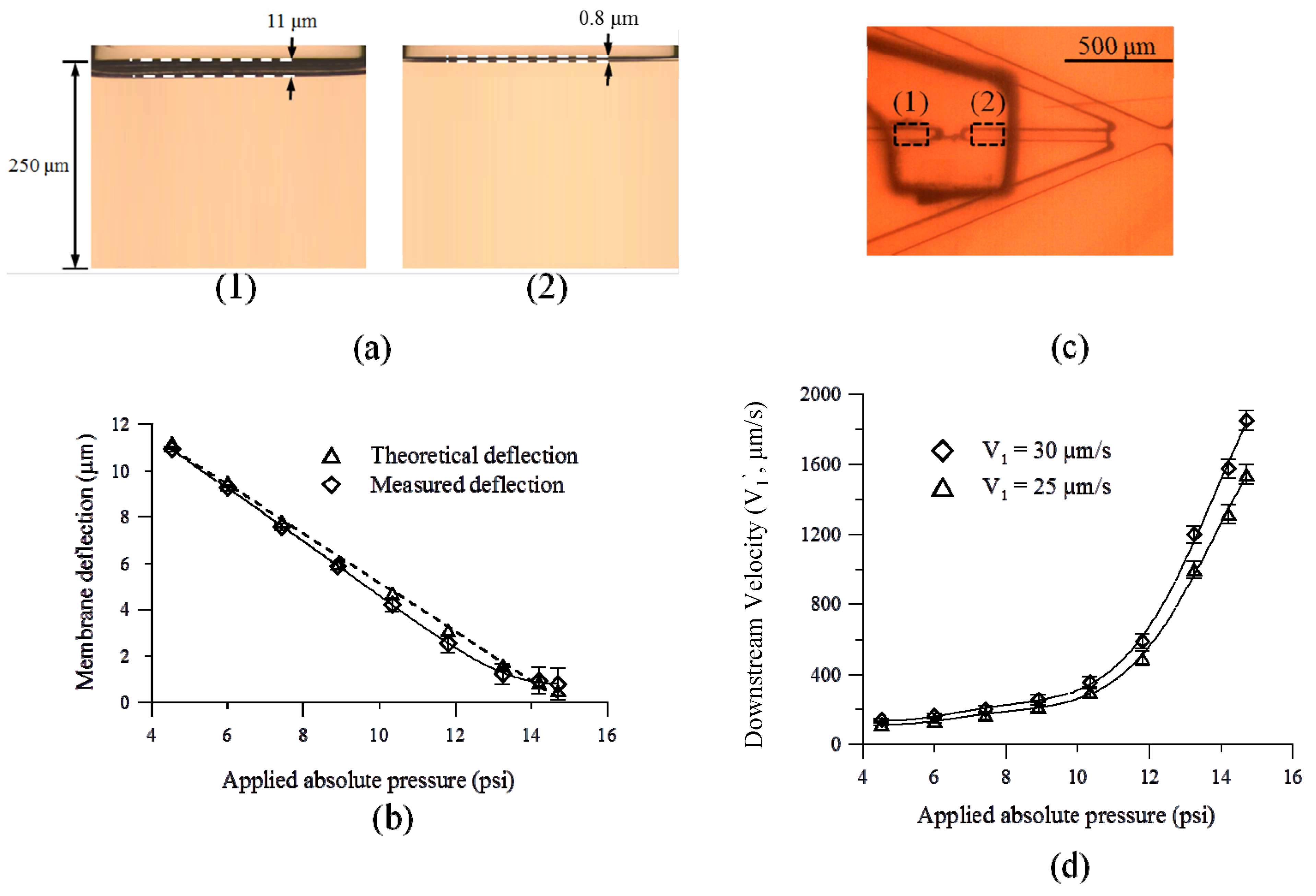
The microfluidic device was used to generate micro-droplets with sizes ranging from 5.5 to 55 μm. The membrane deflection of the NC micro-valve was first characterized. The deflection of the membrane was measured via a side-view image by using a camera (FinePix S5 Pro, Fujifilm, Tokyo, Japan) with a high magnification lens, as shown in
Figure 4a.
Figure 4b shows the relationship between the membrane deflections and the applied absolute pressure. In addition, the theoretical deflection of the suction membrane can be calculated using the following formula [
35]:
where
P is the applied “absolute” pressure,
a is the equivalent diaphragm radius of 500 μm,
E is the Young’s modulus (about 0.8 MPa for PDMS),
h is the diaphragm thickness of 100 μm,
ν is the Poisson’s ratio (0.5 for PDMS), and
y is the center deflection of the diaphragm. In the Formula (1), the applied “absolute” pressure with a unit of Pa, P, was defined as the total of the atmospheric pressure and the gauge pressure. Note that the gauge with the vacuum pressure was used in this approach, and the applied absolute pressure was used with a unit of psi in this study. The dimensions of the suction membrane are 50, 100, and 100 μm in width, length and thickness, respectively. The dotted line in
Figure 4b is the theoretical deflection of the membrane, which is calculated from Formula (1). As expected, a larger membrane deflection is generated at lower applied absolute pressures (a larger suction force). In addition, the measured deflection of the membrane is in agreement with the calculations. In this study, a maximum measured deflection of 11 μm is generated at an applied absolute pressure of 4.5 psi. Therefore, droplets with smaller diameters can be generated since the velocity of the dispersed-phase liquid is varied by tuning the deflection of the suction membrane. Note that an initial membrane defection of 0.8 μm exists when the syringe pumps are activated.
As described above, the downstream velocity of the dispersed-phase liquid can be varied by fine-tuning the deflection of the suction membrane to generate droplets with smaller diameters.
Figure 4c shows the regions of the microfluidic chip where the upstream and downstream flow velocities were measured. Note that the motion of 10-μm polystyrene beads flowing through a 100-μm distance was recorded by a high-speed CCD camera with an image acquisition rate of 1000 Hz to measure the downstream velocity of the dispersed-phase liquid (
V1’) before the micro-droplets were produced. The flow velocities 200-μm upstream and downstream of the NC micro-valve, respectively, were measured. The time that the beads flowed through a 100-μm distance would be measured and averaged. Then, the upstream and downstream velocities were calculated accordingly. Here, the downstream flow velocity was measured before the micro-droplets were produced.
Figure 4d shows that the downstream velocity of the dispersed-phase liquid (
V1’) after flowing through the NC micro-valve when operated at different applied absolute pressures. In this approach, the flow cross-section region would be reduced since the fluid flowed through the sub-micro or nano-channel. Based on the continuity equation of fluid, the velocity of the fluid would be increased with the decreasing of the flow region. Therefore, the velocity of the flow in the vicinity of the flow focusing would be higher than that far upstream of the valve. The velocity of the continuous-phase liquid (
V2) was set at 50 μm/s in this case. Note that two experiments were performed with syringe pump flow rates for the dispersed-phase liquid set at 3.75 and 4.50 μL/min. respectively. Therefore, the upstream (initial) velocities of the dispersed-phase liquid (
V1) were kept at 25 and 30 μm/s, respectively. With a constant volume flow rate provided by the syringe pump, the downstream velocity of the dispersed-phase liquid can be varied by changing the depth of the channel which can be adjusted by fine-tuning the deflection of the suction membrane. As expected, the downstream velocity decreases with the increasing suction force (
i.e., a decrease in the absolute pressure). In this study, the maximum
V1’ was found to be 1850 μm/s when the deflection of the membrane was 0.8 μm with an applied absolute pressure of 14.7 psi (without any applied suction force).
Figure 4.
(a) The maximum deflection of membrane were measured as (1) 11 μm (for 4.5 psi) and (2) 0.8 μm (for 14.7 psi), respectively. (b) The membrane deflection of the NC micro-valve at different applied absolute pressures. Note that the initial membrane defection is 0.8 μm when the syringe pumps are activated. (c) The upstream and downstream flow velocities were measured in the (1) upstream and (2) downstream regions which were distant form the NC valve with 200 μm, respectively. (d) The downstream velocity of the dispersed-phase liquid (V1’) after flowing through the NC micro-valve when operated at different suction pressures. The velocity of the continuous-phase liquid (V2) is set at 50 μm/s. Two experiments with two different upstream (initial) velocities of the dispersed-phase liquid (V1) of 25 and 30 μm/s, respectively, are performed.
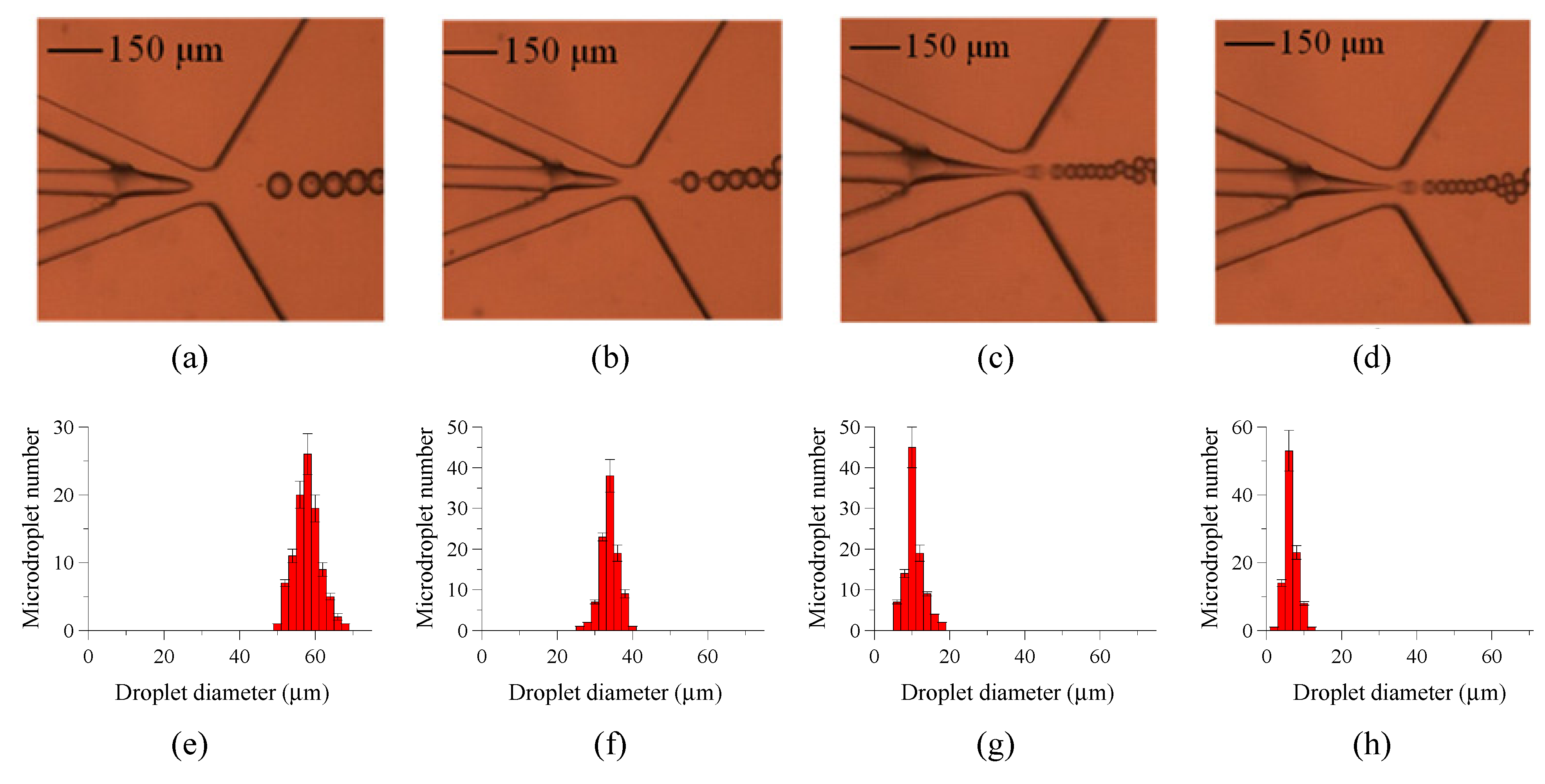
Figure 5 shows successful formation of emulsion micro-droplets at different applied absolute pressures by deforming the suction membrane of the NC micro-valve. In order to better understand the relationship between the droplet size and the applied absolute pressure, this study only shows the distributions and uniformity of the droplets at the maximum, a selected sub-maximum, the minimum, and the mean applied absolute pressure. Therefore, the applied absolute pressures are 4.5 psi, 10.4 psi, 14.2 psi, and 14.7 psi, respectively. In this case,
V2 is kept constant (50 μm/s), and
V1 of the dispersed-phase liquid is set at 30 μm/s. It can be clearly seen that the size of emulsion droplets with a low CV value can be well controlled by changing the deflection of the suction membrane. The deflections of the suction membrane were measured to be 10.9 μm for 4.5 psi, 4.2 μm for 10.4 psi, 0.9 μm for 14.2 psi, and 0.8 μm for 14.7 psi, respectively. The average droplet diameters were measured to be 58 μm, 34 μm, 10 μm, and 5.5 μm, respectively, for these four cases. The CVs in droplet size were measured to be 3.8%, 3.3%, 2.9%, and 2.5%, respectively. It was difficult for the formation of droplet by using the T-junction microchannel since the high velocity of the dispersed-phase liquid would break the continuance-phase flow to spot the droplet formation. Compared to the previous study using the flow focusing method [
12,
36,
37], which reported emulsion droplets with a smallest diameter of 20 μm and a CV of more than 3%, the current device has a superior performance because it generates droplets with a smaller diameter (5.5 μm) with a CV of only 2.5%. In addition, it also has a better performance when compared with other devices that use tunable structures (with a smallest diameter of 10 μm for these other devices) [
38,
39,
40]. Smaller droplets with a diameter of several micrometers could be also generated using a similar approach. In this study, the smallest droplet diameter was observed to be 5.5 μm when applying an absolute pressure of 14.7 psi.
Figure 5.
Formation of micro-droplets using the NC micro-valve with different applied absolute pressures. The size of the emulsion droplets can be precisely controlled using the micro-valve operated at different applied absolute pressures. Average droplet diameters are measured to be (a) 58 μm (for 4.5 psi), (b) 34 μm (for 10.4 psi), (c) 10 μm (for 14.2 psi), and (d) 5.5 μm (for 14.7 psi), respectively. The histograms of size distributions with a total number of 100 micro-droplets for applied absolute pressures of (e) 4.5 psi, (f) 10.4 psi, (g) 14.2 psi, and (h) 14.7 psi, respectively. The CVs in droplet sizes were measured to be 3.8%, 3.3%, 2.9%, and 2.5%, respectively. The V1 and V2 are set at 30 and 50 μm/s, respectively. The droplet diameter without applying any suction force is 5.5 μm.
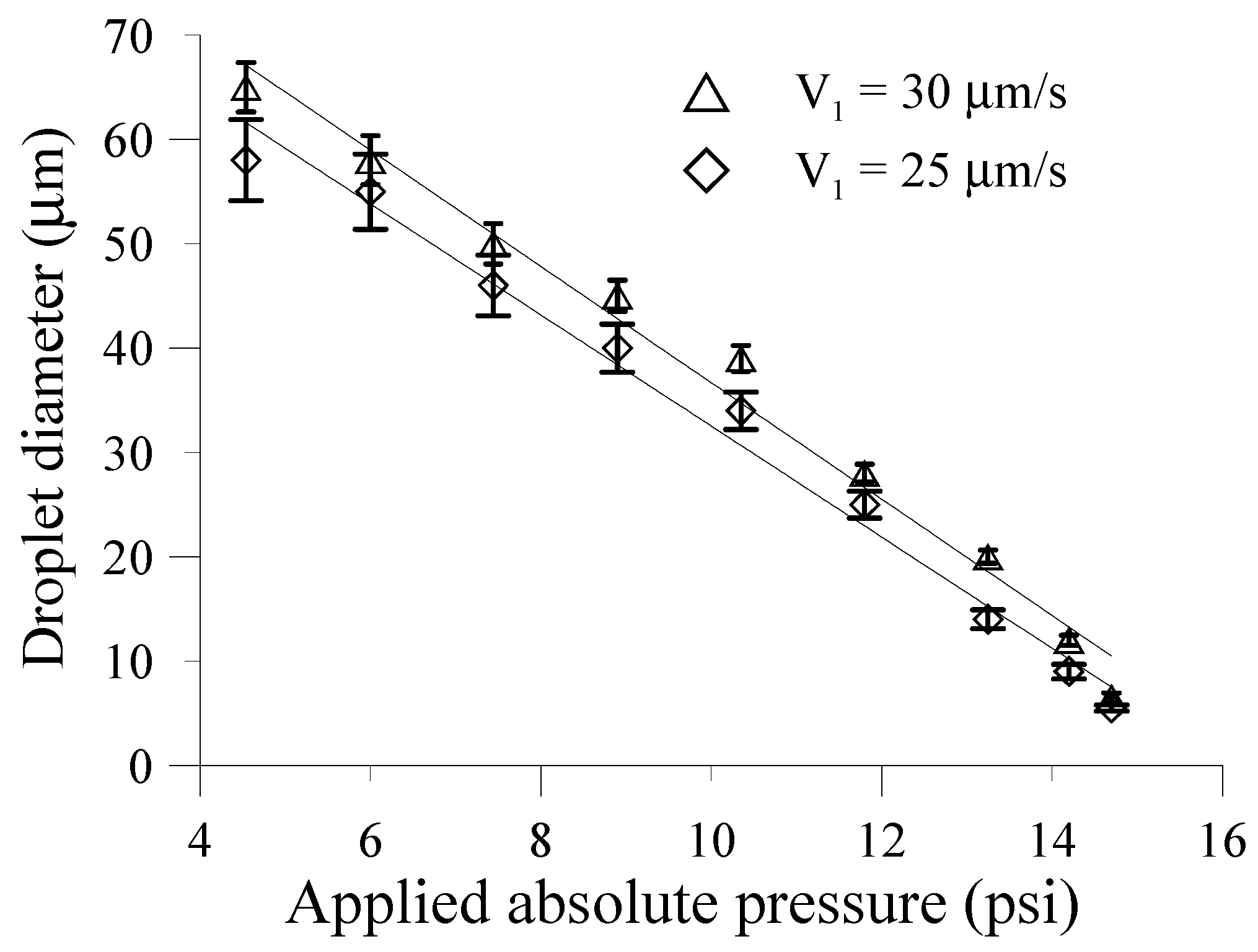
Figure 6 shows the relationship between the average diameters of the droplets and the applied absolute pressures. Again, two experiments with
V1 of 25 and 30 μm/s, respectively, for the dispersed-phase liquid were conducted. Static applied absolute pressures ranging from 4.5 psi to 14.7 psi were used to form the micro-droplets in this case. It is clearly seen that diameter of the droplets is well controlled by using the deflection of the suction membrane. As expected, as the applied pressure decreases, the size of the droplet increases accordingly. This is because an increase in the suction force causes more deflection of the membrane, thus increasing the cross sectional area of the channel as shown in
Figure 4a. Therefore, the size of the micro-droplets increases accordingly. When the applied pressure was higher than 14.7 psi, the micro-valve would block up the microchannel and the dispersed-phase could not flow through. Therefore, no emulsions can be observed. In addition, the average diameter of the micro-droplet also decreases with a decrease in
V1. The smallest droplet diameters without opening the micro-valve are 6.5 and 5.5 μm when
V1 is 25 and 30 μm/s, respectively. Compared to the droplets generated by using a microchannel with the moving structure, this device can successfully generate droplets with smaller diameters in a simple manner without using delicate fabrication processes to create the extremely small center channel.
Figure 6.
The relationship between the average diameters of the droplets and the applied absolute pressures. The V2 is kept constant (50 μm/s). The smallest droplet diameters without opening the micro-valve are 6.5 and 5.5 μm when the V1 are 25 and 30 μm/s, respectively.
Figure 6.
The relationship between the average diameters of the droplets and the applied absolute pressures. The V2 is kept constant (50 μm/s). The smallest droplet diameters without opening the micro-valve are 6.5 and 5.5 μm when the V1 are 25 and 30 μm/s, respectively.
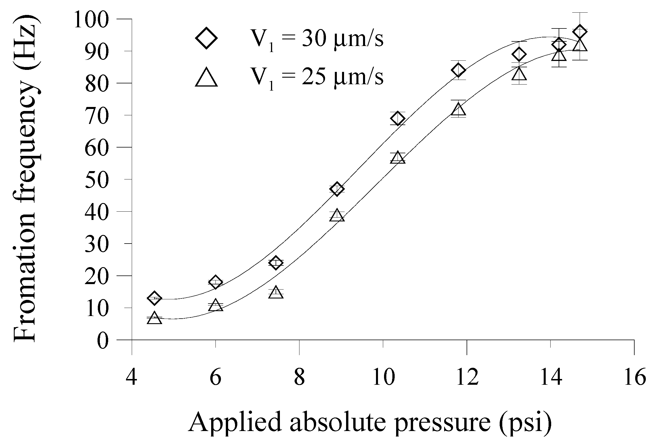
The droplet formation frequency, which is defined by the number of droplets generated within a set period of time, is also explored.
Figure 7 shows the relationship between the droplet formation frequency and the applied absolute pressures on the suction membrane.
V2 is kept constant at 50 μm/s. The droplet formation frequency clearly increases with the increase in the applied absolute pressure when the
V1’ increases with the decreasing deflection of the suction membrane. When no suction force (at an applied absolute pressure of 14.7 psi) is applied to the membrane structure, the external syringe pump still delivers a discrete volume of fluid to overcome the NC valve mechanism. Therefore, the pressure of the discrete flowing fluid build behind the NC valve to flow pass downstream, and the droplet formation frequency is as high as 96 and 94 Hz, respectively, for corresponding
V1’ of 1850 and 1575 μm/s. Note that when the smallest absolute pressure of 4.5 psi is applied, the droplet formation frequency is only around 13 and 7 Hz for corresponding
V1’ of 135 and 115 μm/s. Actually, the less pressure of the flowing fluid is required to overcome the NC valve mechanism since the NC valve is always driven with the applied pressure. For this season, the size and formation frequency of droplet were determined by the flow ratios of the dispersed-phase liquid to the continuous-phase liquid.
Figure 7.
The relationship between the droplet formation frequency and the applied absolute pressures on the suction membrane. The V2 is constant at 50 μm/s.
Figure 7.
The relationship between the droplet formation frequency and the applied absolute pressures on the suction membrane. The V2 is constant at 50 μm/s.
In addition to use the NC micro-valve to control the gap statically, it is a membrane structure allowing vertical movement and therefore the suction membrane can be also used as an active chopper to partition the liquid streams during the droplet formation process. Previous works reported that the diameter of the droplets decreased with an increase in the chopping frequency [
22,
23,
24,
26,
31,
34]. However, those active choppers were used to break a “pre-focused” stream into micro-droplets. In this study, the effect of the chopping frequency of the suction membrane is explored, which partitions the stream before the flow focusing process. For the minimum membrane deflection of 0.8 μm without any suction force (the applied absolute pressure is 14.7 psi), the suction membrane driven at different frequencies from 0 Hz to 60 Hz could not break the continuity of the liquid stream since
V1’ is too high. Besides, the maximum deflection of 11 μm (at an applied absolute pressure of 4.5 psi) could not be achieved at high driving frequencies ranging from 35 Hz to 60 Hz, also to break the continuity of the stream. Therefore, an absolute pressure of 10.4 psi was chosen to explore the relationship between the driving frequency of the EMV and the resulting droplet sizes. Note that the deflection of the suction membrane when driven at an applied absolute pressure of 10.4 psi is 4.2 μm.
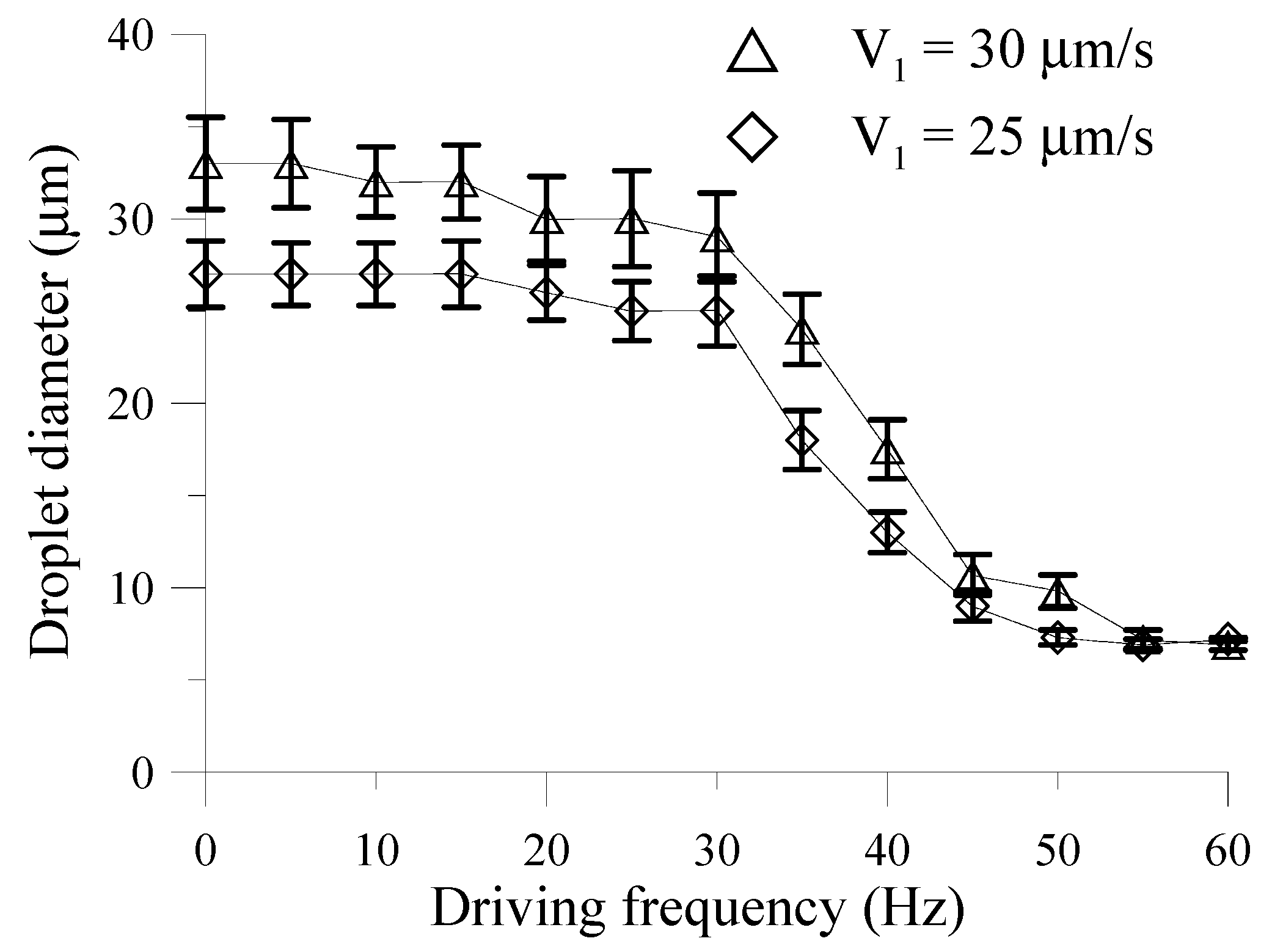
Figure 8 shows the relationship between the droplet diameters and the driving frequencies of the EMVs at a mean applied absolute pressure of 11.8 psi. It can be clearly seen that the diameters of the droplets vary significantly when the driving frequency of the EMV is changed from 30 Hz to 50 Hz. It is seen in
Figure 8 that droplets with the smallest diameter of 7.0 and 6.5 μm for corresponding
V1 of 25 and 30 μm/s, respectively, can be successfully generated. However, the droplet size does not change significant at lower driving frequencies (less than 30 Hz) or at higher driving frequencies (higher than 50 Hz).
The droplet formation frequency at 10.4 psi was found to be 57 Hz (
Figure 7). Therefore, when the chopping frequency is too low, it does not affect the formation of the droplet and the resulting droplet size. If the chopping frequency is close to the droplet formation frequency, then the droplet can be effectively chopped into a smaller size, as shown in
Figure 8. However, when the chopping frequency is too high, the release time of the applied pressure limits the complete deflection of the suction membrane; therefore, the chopping is not effective [
41,
42].
Figure 8.
The relationship between the average diameter of the droplets and the driving frequency of the EMV at an applied absolute pressure of 10.4 psi. The V2 is 50 μm/s, and the V1 are 30 μm/s and 25 μm/s, respectively.
Figure 8.
The relationship between the average diameter of the droplets and the driving frequency of the EMV at an applied absolute pressure of 10.4 psi. The V2 is 50 μm/s, and the V1 are 30 μm/s and 25 μm/s, respectively.

