Article

Integrated Control Strategies for a Precision Long-Travel Stage: Applications in Micro-Lens Fabrication

1
Department of Mechanical Engineering, National Taiwan University, Taipei 10617, Taiwan
2
Department of Mechanical Engineering, National Taiwan University of Science and Technology, Taipei 10617, Taiwan
*
Author to whom correspondence should be addressed.
Micromachines 2025, 16(10), 1105; https://doi.org/10.3390/mi16101105
Submission received: 2 September 2025 / Revised: 24 September 2025 / Accepted: 26 September 2025 / Published: 28 September 2025
(This article belongs to the Topic Innovation, Communication and Engineering)

Abstract

This paper develops multiple control strategies for a precision long-travel stage, which comprises motor and piezoelectric transducer (PZT) stages. First, the PZT stage is equipped with control switching and model estimation mechanisms to achieve nm-level precision within 100 μm distances. The control switching mechanism selects the optimal control sequences by predicting system responses, while the model estimation algorithm updates the system model to improve the prediction accuracy. Second, the motor stage is equipped with gain-scheduling and feedforward control mechanisms to achieve a maximum displacement of 100 mm with a resolution of 0.1 μm. The gain scheduling control modifies the control gain in accordance with tracking errors, while the feedforward control can mitigate phase lags. We integrate the stages to achieve nm-level precision over long travels and conduct simulations and experiments to show the advantages of the control mechanisms. Finally, we apply the long-travel precision stage to fabricate micro-lenses using two-photon polymerization and evaluate the fabricated micro-lenses’ optical characteristics to illustrate the merits of the control strategies.

1. Introduction

The progression of technological advancements has critically increased the demand for high-precision positioning control. Precision engineering now extensively utilizes piezoelectric materials due to their advantageous properties, including rapid response times and high energy efficiency. Nevertheless, the inherent nonlinearities of these materials can significantly impair positioning accuracy. To address these challenges, researchers have developed various nonlinear modeling techniques and control strategies. For example, Chen et al. [1] proposed a hysteresis modeling approach that captured the nonlinear behaviors of piezoelectric actuators. Baziyad et al. [2] introduced an inverse Preisach model and integrated it with support vector machines to compensate for nonlinearities in piezoelectric-driven positioning systems. Keshavarzpour and Ghasemi [3] implemented a hybrid fuzzy proportional-integral-derivative (PID) control to suppress sound radiation and enhance disturbance rejection. McCartney et al. [4] proposed a compact model for a piezoelectric transistor to simulate nanoscale electromechanical behavior. However, these design approaches have not been entirely successful in eliminating the nonlinearities associated with piezoelectric materials.
Control system design typically involves balancing multiple, and often conflicting, performance criteria. For example, some controllers provide rapid responses but may result in significant overshoots, whereas others provide smoother responses but at the cost of prolonged settling times. To overcome the limitations of fixed controllers, numerous studies have investigated the use of switching control strategies that can provide dynamic adaptation to system conditions. For instance, Kim et al. [5] developed a mode-switching control scheme that integrated optimal servomechanisms and time-delay control to improve positioning accuracy and reduce transition errors in manufacturing equipment. Bashash et al. [6] implemented a switched-control mechanism that transited between two controllers according to position errors to fabricate a piezoelectric transducer (PZT) stage. Li et al. [7] combined trajectory planning and nonlinear feedback to develop a switching mode control for motor systems. Artetxe et al. [8] built a combined control using feedforward neural networks and sliding mode control to suppress hysteresis and improve tracking accuracy. However, these approaches did not address all the issues hindering the control of precision stages.
An integral control method for precision stages, proposed in [9], eliminated steady-state errors and outperformed fixed-gain controllers through adaptive adjustment of the control gain according to position errors. Zhang and Yan [10] proposed an infinite-dimensional H control method to address feedback delays caused by high-resolution capacitive sensors in piezoelectric nano-positioning stages, where the experimental results outperformed traditional PID and finite-dimensional controllers. Makarem et al. [11] applied direct data-driven iterative tuning to optimize PID parameters for ultrasonic motors using dual-source and dual-frequency driving techniques. Wang et al. [12] introduced a predictive switching control scheme that could switch between two controllers based on predicted responses to reduce settling time and overshoots. A multiple-switching control framework proposed for PZT stages in [13,14] considered future responses by multiple control sequences to provide better performance than using a single-switching scheme. However, these response predictions were based on a nominal plant and ignored variations in operating conditions. For this reason, further system improvement will require updating the models in the response predictors.
Recent studies have highlighted the importance of accurate response prediction in control systems. For example, Smith et al. [15] presented a data-driven predictive control framework that leveraged past input–output trajectories to improve control performance by predicting future responses. Hiraoka et al. [16] developed a database-driven PID controller that could handle unknown time-delay systems through response prediction. This paper proposes a model estimation mechanism that can estimate the system model in real time and apply it to forecast responses, thereby improving both prediction accuracy and control performance. We can then integrate model estimation and control switching mechanisms and conduct simulations and experiments.
While the PZT stage can achieve nm-level precision, its travel range is limited. To overcome this limitation, we integrated it with a motor stage to provide long-range motion with nanometer-level precision. We then developed gain-scheduling and feedforward control frameworks for the motor stage. The former adjusts control gains based on tracking errors, while the latter compensates for phase lag, thereby improving overall system responsiveness and accuracy. Finally, we integrated the motor and PZT stages and verified the effects of the proposed control strategies through simulations and experiments. Subsequently, the integrated stage was employed to fabricate micro-lenses via two-photon polymerization. We then evaluated the lenses’ optical properties to highlight the merits of the proposed strategies.
The paper is arranged as follows: Section 2 depicts the precision long-travel stage and models. Section 3 introduces control switching and model estimation mechanisms for PZT stages. Section 4 depicts the gain-scheduling and feedforward mechanisms for motor stages. Section 5 integrates the stages and evaluates system performance through simulations and experiments. Section 6 applies the integrated stage to fabricate micro-lenses and evaluate the effectiveness of the control by characterizing the lenses’ optical properties. Finally, Section 7 concludes the study.

2. The Long-Travel Precision Stage

This section depicts the long-travel precision system, which integrates PZT and motor stages (see Figure 1). The former has encoders with resolutions of 1.22 nm and a travel of 100 μm [17]. In contrast, the latter has a 100 mm-travel and 1 μm-resolution [18,19]. An interferometer was applied as a global sensor in [20] to verify the encoder-sensor layouts. The system specifications are available in Appendix A [17,18,19]. By combining these stages, the system can achieve nanometer-level positioning accuracy over centimeter-scale distances. This section also presents the modeling of both stages and the design of their respective control strategies.

2.1. PZT Stage Models

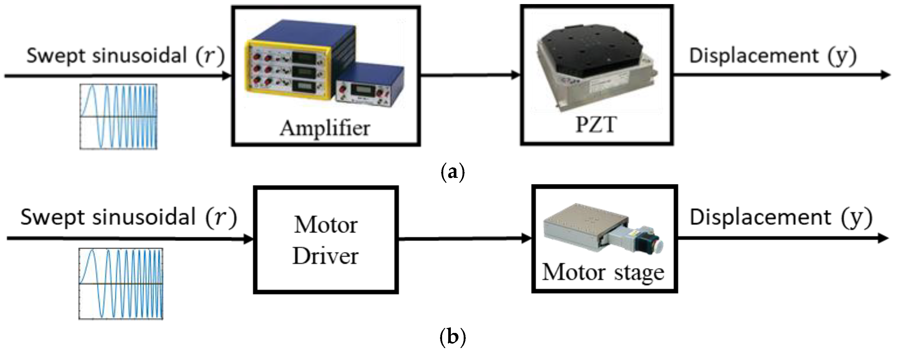
We used experiments to derive the stage models, as shown in Figure 2a, by applying a swept sinusoidal signal as the system input r and measuring the stage displacements y to derive the stage model. An amplifier magnified the driving signals to regulate the stage travels within a range of 0–100 μm.
The identification processes were repeated to derive ten models for the x-axis, as illustrated in Appendix B. A nominal plant G 0 was then chosen for control designs in Section 3 based on gap metric principles [21]. Suppose G 0 = M ˜ 1 N ˜ , where M ˜ ,   N ˜ R H and M ˜ M ˜ * +   N ˜ N ˜ * =   I . A perturbed plant G Δ = M ˜ + Δ M ˜ 1 N ˜ + Δ N ˜ represents the actual physical system and is different from the mathematical model G 0 . The gap between G 0 and G Δ is labeled as δ ( G 0 , G Δ ) , which is the smallest ε such that Δ = Δ M ˜ Δ N ˜ with Δ ε can perturb G 0 into G Δ [22]. Based on the gap analysis, we selected the following nominal plants for control designs:
G P x = arg min G i x max G j x δ g ( G i x , G j x ) ,   i , j = 1 ,   2 ,   ,   10 = G 3 x = 2.02 × 10 3 s 3 + 1.22 × 10 6 s 2 + 1.45 × 10 9 s + 3.25 × 1 0 10 s 4 + 6.49 × 10 2 s 3 + 1.02 × 10 6 s 2 + 1.95 × 10 8 s + 3.60 × 10 9 ,
Here, δ ( G P x , G i x ) 0.0556 ,   G i x minimizes the maximum gaps among all models.
Similarly, we derived ten models for the y-axis of the PZT stage, as illustrated in Appendix B, and selected the following nominal plant for control designs in Section 3:
G P y = arg min G i y max G j y δ g ( G i y , G j y ) ,   i , j = 1 ,   2 ,   ,   10 = G 5 y = 7.02 × 10 2 s 3 + 4.25 × 10 5 s 2 + 6.98 × 10 8 s + 3.64 × 1 0 9 s 4 + 2.90 × 10 2 s 3 + 5.07 × 10 5 s 2 + 7.87 × 10 7 s + 2.02 × 10 9 ,
which minimizes the maximum gaps among all models, with δ ( G P y , G i y ) 0.0810 ,   G i y .

2.2. Motor Stage Models

The models of the motor stage were also derived through experiments by applying a signal r as input and measuring the output y (see Figure 2b). Based on gap analyses, the experiments were also repeated to derive ten models on each axis, as illustrated in Appendix B. Based on the gap metrics, the following nominal plants were then selected for control design in Section 4.
G M x = 0.1007 s ,   G M y = 0.1009 s .

3. Control Switching and Model Estimation for the PZT Stage

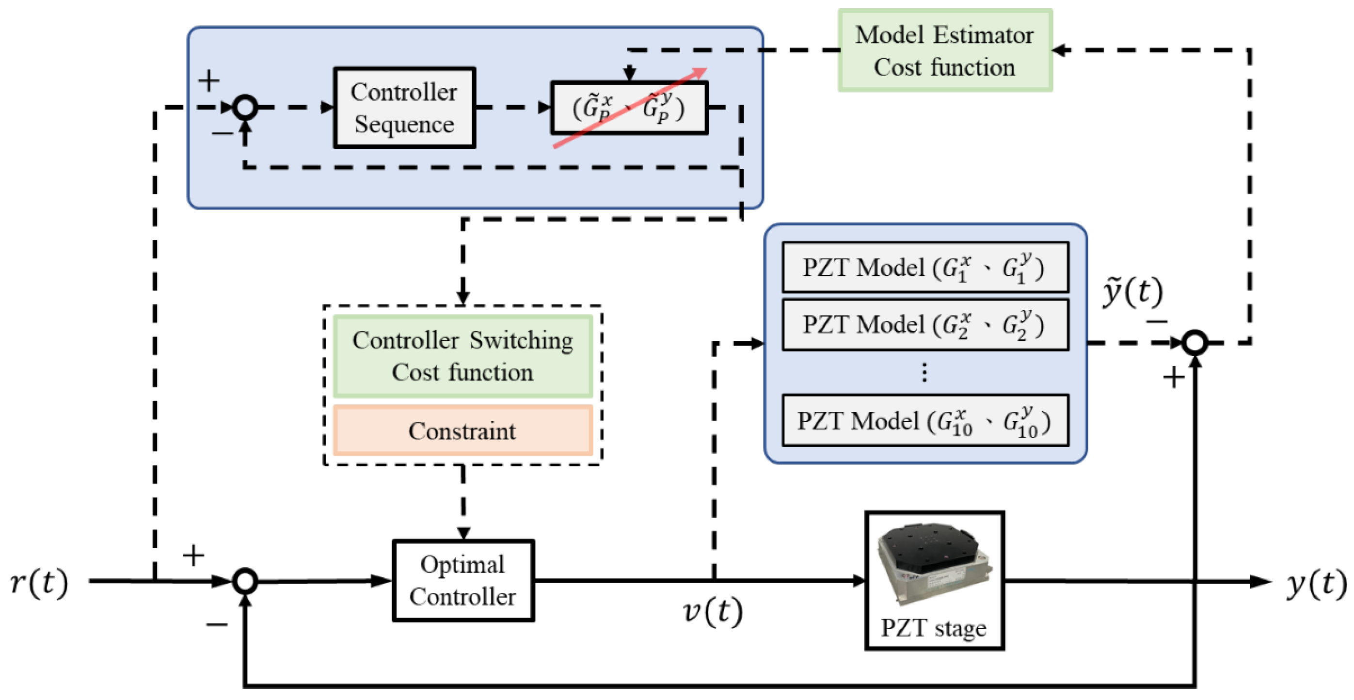
This section introduces the control switching and model estimation mechanisms for the PZT stage, as illustrated in Figure 3.

3.1. Robust Control Designs

We applied G P x   and   G P y for control designs for precision stages. The system’s internal stability can be maintained by a controller K for all plants G Δ with δ ( G 0 , G Δ ) ε if the stability margin is as follows [23]:
b ( G 0 , K ) K I ( I G 0 K ) 1 [ I G 0 ] 1 > ε
We designed controllers K using the loop-shaping technique with a weighted plant G s = G W , as illustrated in Figure 4. The selection of the weighting function W followed three key principles [24,25]: (1) increasing G s ( j ω ) when ω is small; (2) decreasing G s ( j ω ) when ω is large; and (3) letting the slope of d G s ( j ω ) / d ω 40 0   dB around the cross-over frequency. Finally, we implemented the weighted controller K = W K to control G .
We applied the following weighting functions:
W f x = 40 ( s + 40 π ) s ( s + 30 π ) ,   W m x = 20 ( s + 15 π ) s ( s + 30 π )   ,   W s x = 15 ( s + 10 π ) s ( s + 40 π )
W f y = 40 ( s + 60 π ) s ( s + 20 π ) ,   W m y = 15 ( s + 15 π ) s ( s + 40 π )   ,   W s y = 10 ( s + 15 π ) s ( s + 40 π )
and designed the robust controllers using the MATLAB R2024a command ncfsyn:
K f x = 34.36 s 6 + 2.83 × 10 4 s 5 + 3.88 × 10 10 s 3 + 1.29 × 10 10 s 2 +   1.32 × 10 14 s + 5.02 × 10 15 s 7 + 1.14 × 10 3 s 6 + 1.31 × 10 5 s 5 + 6.58 × 10 8 s 4 + 9.62 × 10 10 s 3 +   4.52 × 10 12 s 2 + 6.03 × 10 14 s , K m x = 30.80 s 6 + 1.71 × 10 4 s 5 + 1.65 × 10 7 s 4 + 7.31 × 10 9 s 3 + 7.40 × 10 11 s 2 + 3.26 × 10 13 s + 1.75 × 10 14 s 7 + 9.99 × 10 2 s 6 + 8.71 × 10 5 s 5 + 3.35 × 10 8 s 4 + 4.28 × 10 10 s 3 +   4.18 × 10 12 s 2 + 9.88 × 10 13 s , K s x = 11.10 s 6 + 5.35 × 10 3 s 5 + 6.77 × 10 6 s 4 + 4.18 × 10 9 s 3 + 5.32 × 10 11 s 2 +   7.02 × 10 13 s + 1.05 × 10 14 s 7 + 9.33 × 10 2 s 6 + 7.29 × 10 5 s 5 + 7.92 × 10 8 s 4 + 3.88 × 10 10 s 3 +   5.45 × 10 12 s 2 + 9.87 × 10 13 s ,
K f y = 38.22 s 6 + 5.38 × 10 4 s 5 + 7.06 × 10 7 s 4 + 2.22 × 10 10 s 3 +   2.88 × 10 12 s 2 + 1.58 × 10 14 s + 1.93 × 10 15 s 7 + 1.01 × 10 3 s 6 + 6.87 × 10 5 s 5 + 5.25 × 10 8 s 4 + 7.98 × 10 10 s 3 + 4.76 × 10 12 s 2 + 3.58 × 10 13 s , K m y = 20.64 s 6 + 8.78 × 10 4 s 5 + 9.18 × 10 6 s 4 + 5.38 × 10 9 s 3 + 1.78 × 10 11 s 2 + 8.98 × 10 12 s + 7.58 × 10 13 s 7 + 7.14 × 10 2 s 6 + 6.45 × 10 5 s 5 + 3.61 × 10 8 s 4 + 7.62 × 10 10 s 3 + 1.55 × 10 12 s 2 + 10.33 × 10 13 s , K s y = 17.90 s 6 + 6.38 × 10 4 s 5 + 1.75 × 10 7 s 4 + 5.69 × 10 9 s 3 + 8.58 × 10 11 s 2 + 3.22 × 10 13 s + 9.40 × 10 14 s 7 + 9.03 × 10 2 s 6 + 9.56 × 10 5 s 5 + 5.01 × 10 8 s 4 + 8.55 × 10 10 s 3 + 5.37 × 10 12 s 2 + 1.24 × 10 13 s .
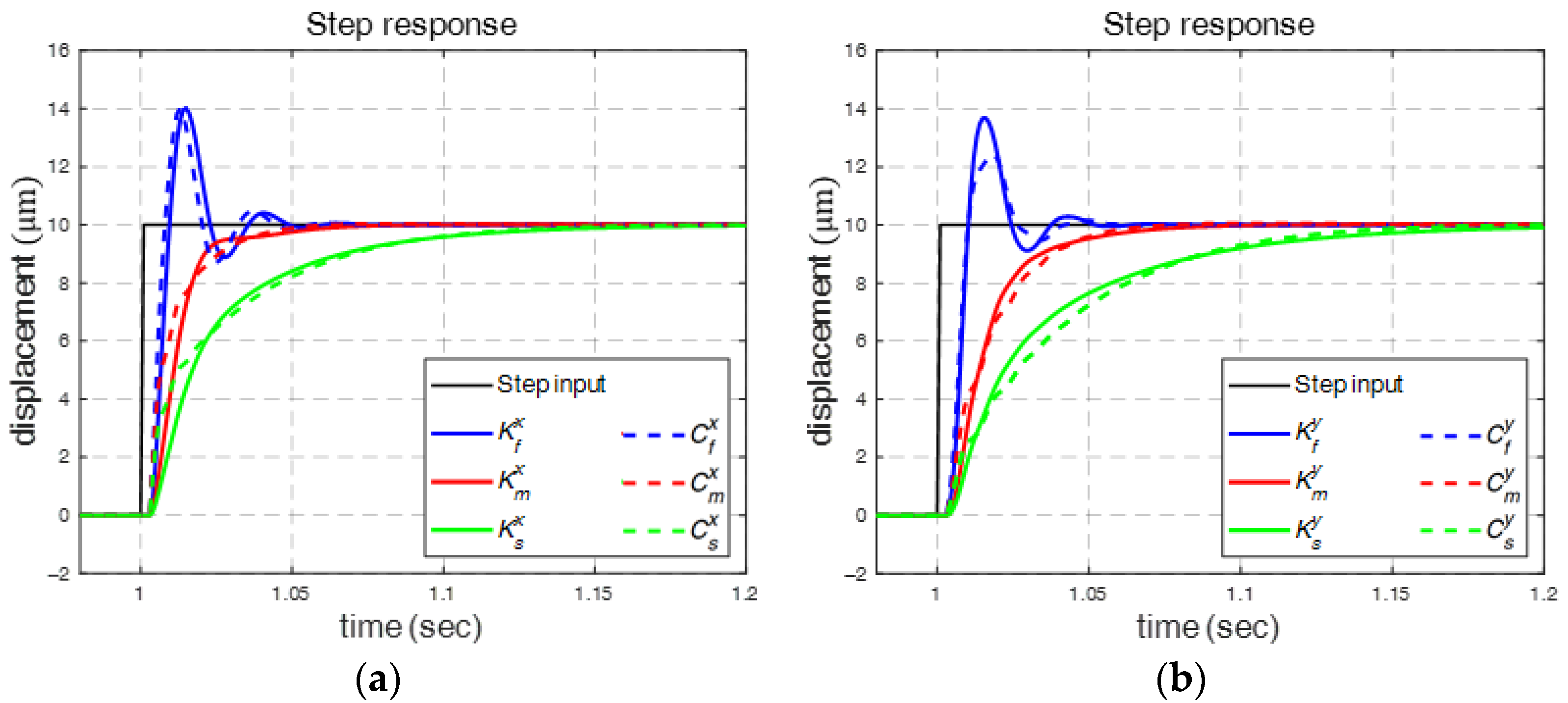
K f i ,   K m i ,   and   K s i denote the fast, medium, and smooth controllers, respectively, for the i-axis, where i x ,   y . These controllers represent different control characteristics, as shown in Figure 5, where K f x   and   K f y produce rapid yet oscillatory responses, while K s x   and   K s y provide smooth but slower responses, and K m x   and   K m y yield a compromise between the rapid and smooth controllers.
We then applied the PSO algorithms [26] to simplify the controllers K f x ,   K m x ,   and   K s x , as follows:
C f x ( s ) = 0.088 + 28.330 s ,   C m x ( s ) = 0.099 + 7.387 s ,   C s x ( s ) = 0.083 + 4.645 s
C f y ( s ) = 0.007 + 39.950 s ,   C m y ( s ) = 0.091 + 7.284 s ,   C s y ( s ) = 0.082 + 4.653 s
These controllers were then converted into discrete time for implementation. The system responses are compared in Figure 5, where C f x ,   C m x ,   and   C s x provide similar responses as K f x ,   K m x ,   and   K s x but with significantly simpler structures. Therefore, we applied these robust PI controllers to control the PZT stage.

3.2. Multiple-Switching Control

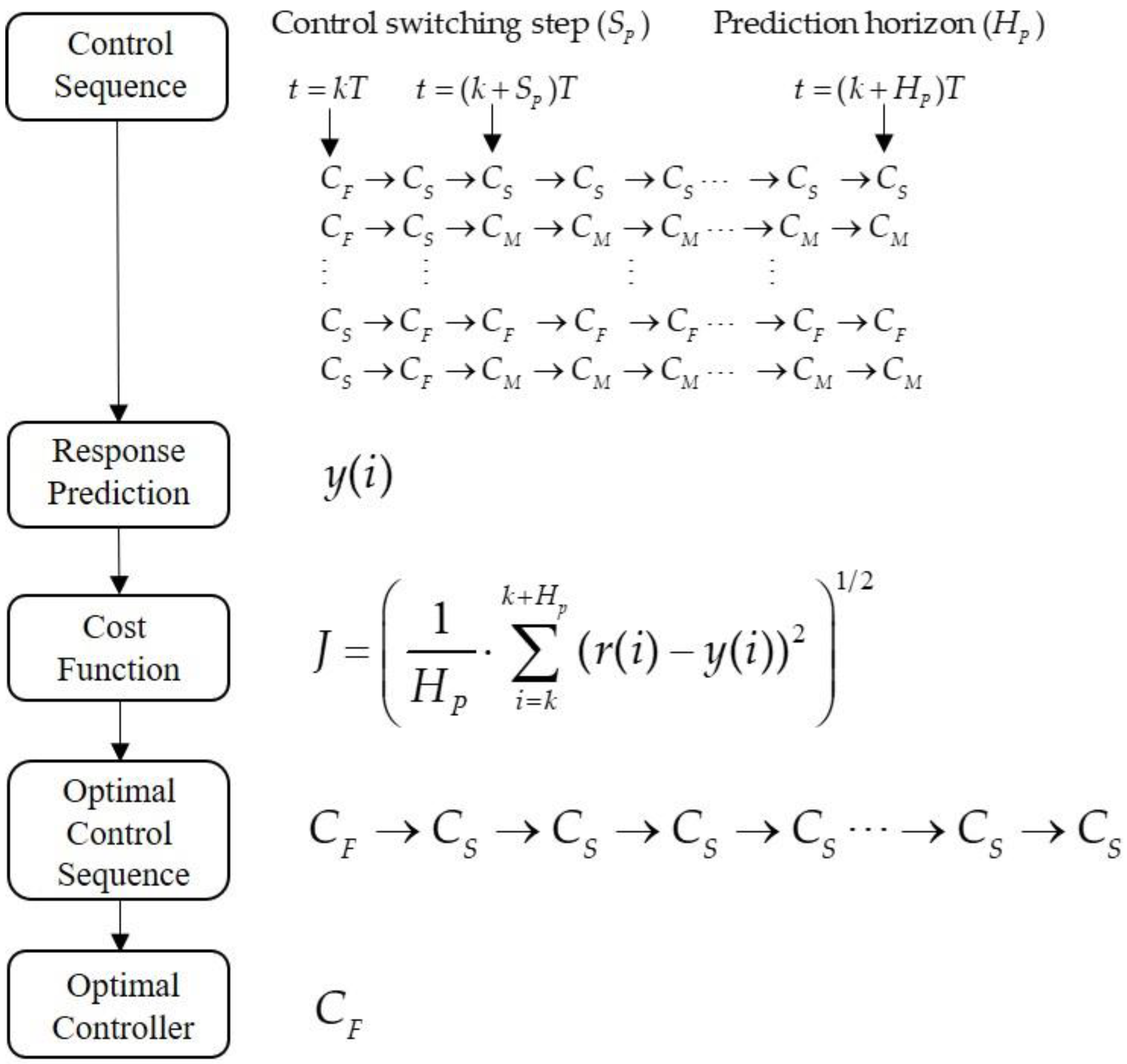
System control usually has multiple control objectives, such as fast responses and limited overshoots, which are difficult to achieve concurrently using a single controller. Therefore, we proposed a multiple-switching control mechanism to determine the most suitable control sequences by predicting system behaviors [14]. The conceptual flow of the integrated switching mechanism is illustrated in Figure 6. The response predictions are based on a controller switching mechanism with three components: (1) the prediction horizon ( H P ), (2) the switching period ( S P ), and (3) the cost function.
The response prediction compares the system responses in the future horizon H P using potential 3 S P control sequences, as shown in Figure 6, and computes the root mean square error (RMSE)
J = 1 H P i = k k + H p ( r ( i ) y ( i ) ) 2 1 / 2
as the cost function. The optimal control sequence, which achieves the minimum cost, is then selected. The corresponding controller is then applied to control the stage.

3.3. Model Estimation

Considering the model variation in the response predictor, we developed a model estimation mechanism that can update the stage model, G i x and G j y , in real time, based on the model input v and output y when predicting the responses. The model was selected to minimize the estimation errors, as follows:
G ˜ P x = arg min G i x y ( k ) y ˜ ( k ) 2 ,   G ˜ P y = arg min G i y y ( k ) y ˜ ( k ) 2
where y represents the measured output and y ˜ is the estimated output when using G i x   and   G j y ,   i , j = 1 ,   2 , ,   10 .
We further integrated the model estimation and multiple-switching control mechanisms to decide on the optimal control sequences in real time. Because the models are updated according to the model input v ( t ) and output y ( t ) , we updated the corresponding controllers as follows:
G i x C f , i x = G P x C f x ;   G i x C m , i x = G P x C m x ;   G i x C s , i x = G P x C s x , G i y C f , i y = G P y C f y ;   G i y C m , i y = G P y C m y ;   G i y C s , i y = G P y C s y ,
to maintain the same loop transfer functions. The modified controllers are summarized in Appendix C.
Implementing the control mechanisms, we conducted experiments with a step input of 10 μm. Table 1 shows the comparison of system performance, including the overshoot, RMSE, settling time, and rise time, to highlight the effects of the proposed mechanisms. Although the rise time shows a slight regression, its influence on overall performance does not pose a substantial issue and can be neglected.

4. Gain Scheduling and Feedforward for the Motor Stage

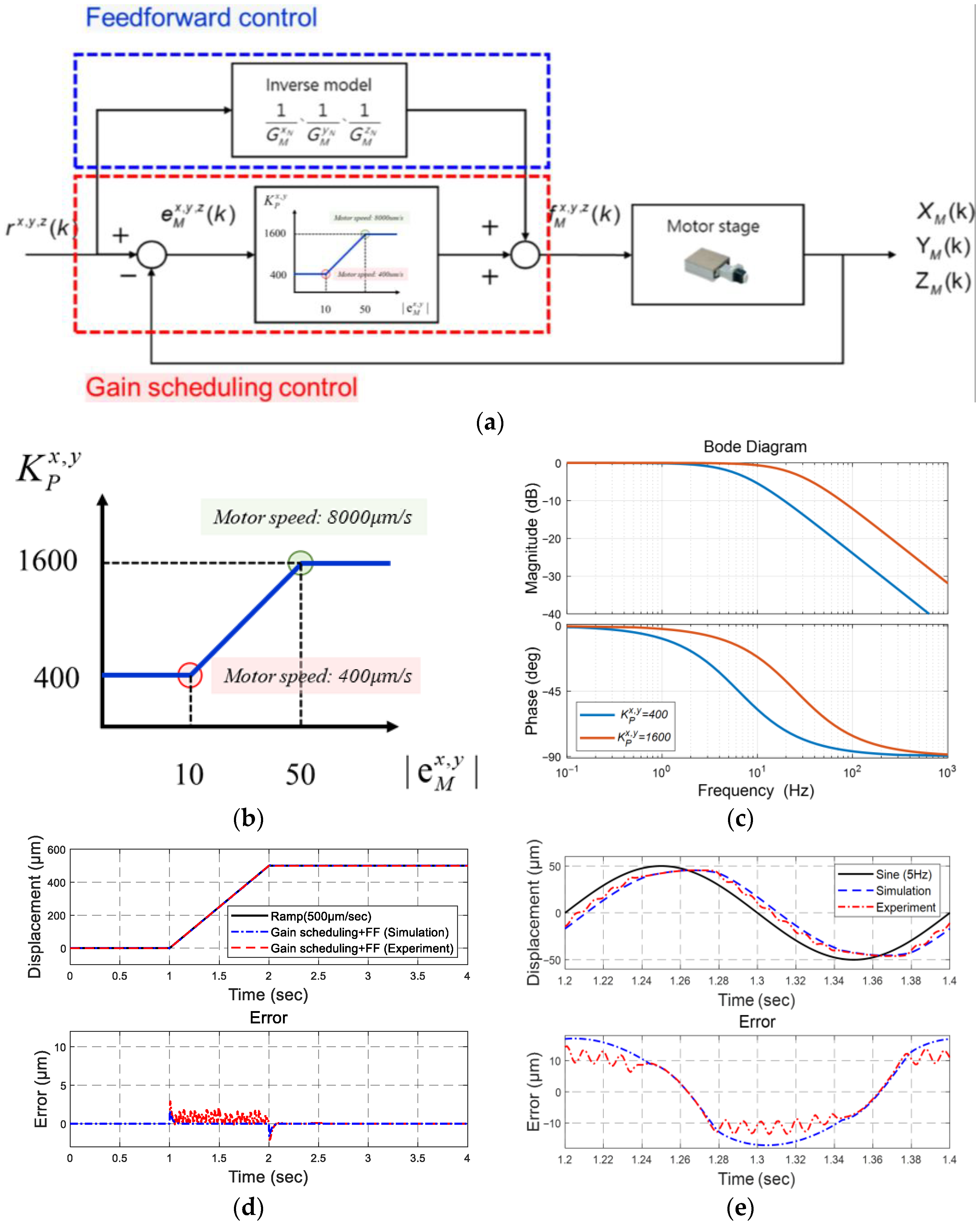
We designed gain scheduling and feedforward mechanisms [13] for the motor stage (see Figure 7a). Because these are first-order models, a constant control K p can arbitrarily assign closed-loop poles. In addition, feedforward can enhance closed-loop responses by mitigating phase lags.

4.1. Gain Scheduling

We can adjust the controller gain K p accordingly to tracking errors e M , as follows (see Figure 7b):
  K P = 1600 ,   if   e M > 50   μ m , 30 e M 10 + 400 ,   if   10 e M 50   μ m 400 ,   i f   e M < 10   μ m . ,
We set the maximum gain as 1600 because the maximum motor speed is 80,000 pulse/s, so the motor can reduce the tracking errors at the maximum speed when they are larger than 50 μm. The minimum gain was set to 400 when the tracking errors are less than 10 μm, allowing the PZT stage to compensate for the tracking errors of the combined stage smoothly.
The system’s Bode plots, illustrated in Figure 7c, show significant phase lags in the middle frequency range. Therefore, a feedforward mechanism was developed to reduce the phase lag.

4.2. Feedforward Compensation

A feedforward control can compensate for a phase lag by employing inverse motor-stage models. Since the inverse models are inherently improper, we designed the feedforward controllers by adding one additional pole, as follows:
C C F F x = s 0.0001 s + 0.1007 ,   C C F F y = s 0.0001 s + 0.1009
For example, given a ramp input of 500 μm/s and a sinusoidal input of 5 Hz, the tracking results shown in Figure 7d,e, and Table 2 illustrate the effects of the feedforward and gain scheduling control.

5. Integration of the Long-Travel Precision Stage

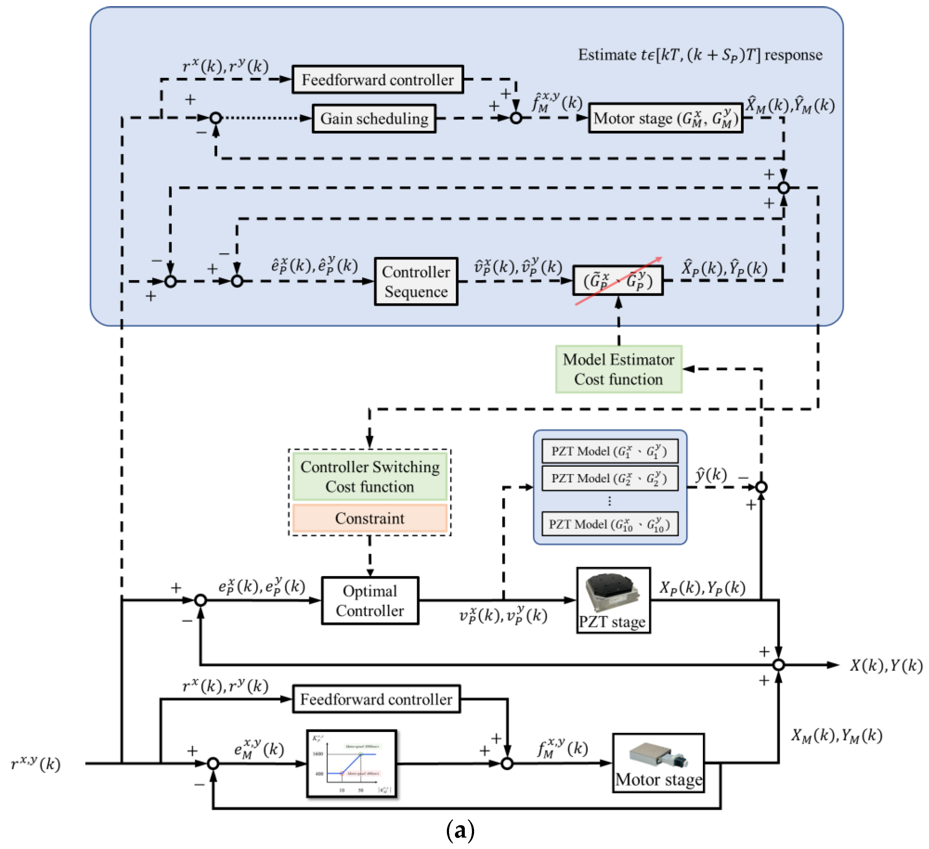
The PZT and motor stages were integrated, as illustrated in Figure 8a. For the PZT stage, the model estimator selects the optimal model and updates the corresponding controllers, while the response predictor forecasts the system responses and chooses the best control sequences. For the motor stage, the control gains were modified according to the tracking errors, while the feedforward control compensated for the phase lags.
Because the PZT had limited travel, the following function was implemented to prevent saturation:
e P i ( k ) = 0 ,   if   e ( k ) 50   μ m e ( k ) ,   otherwise ,   i x ,   y
where e x ( k ) = r x ( k ) X P ( k ) X M ( k ) and e y ( k ) = r y ( k ) Y P ( k ) Y M ( k ) denote the tracking errors of the integrated stage. The motor stage was applied for large-range positioning. Once the overall tracking error was less than 50 μm, the PZT stage could then achieve precision positioning by compensating for the errors e P x   and   e P y .
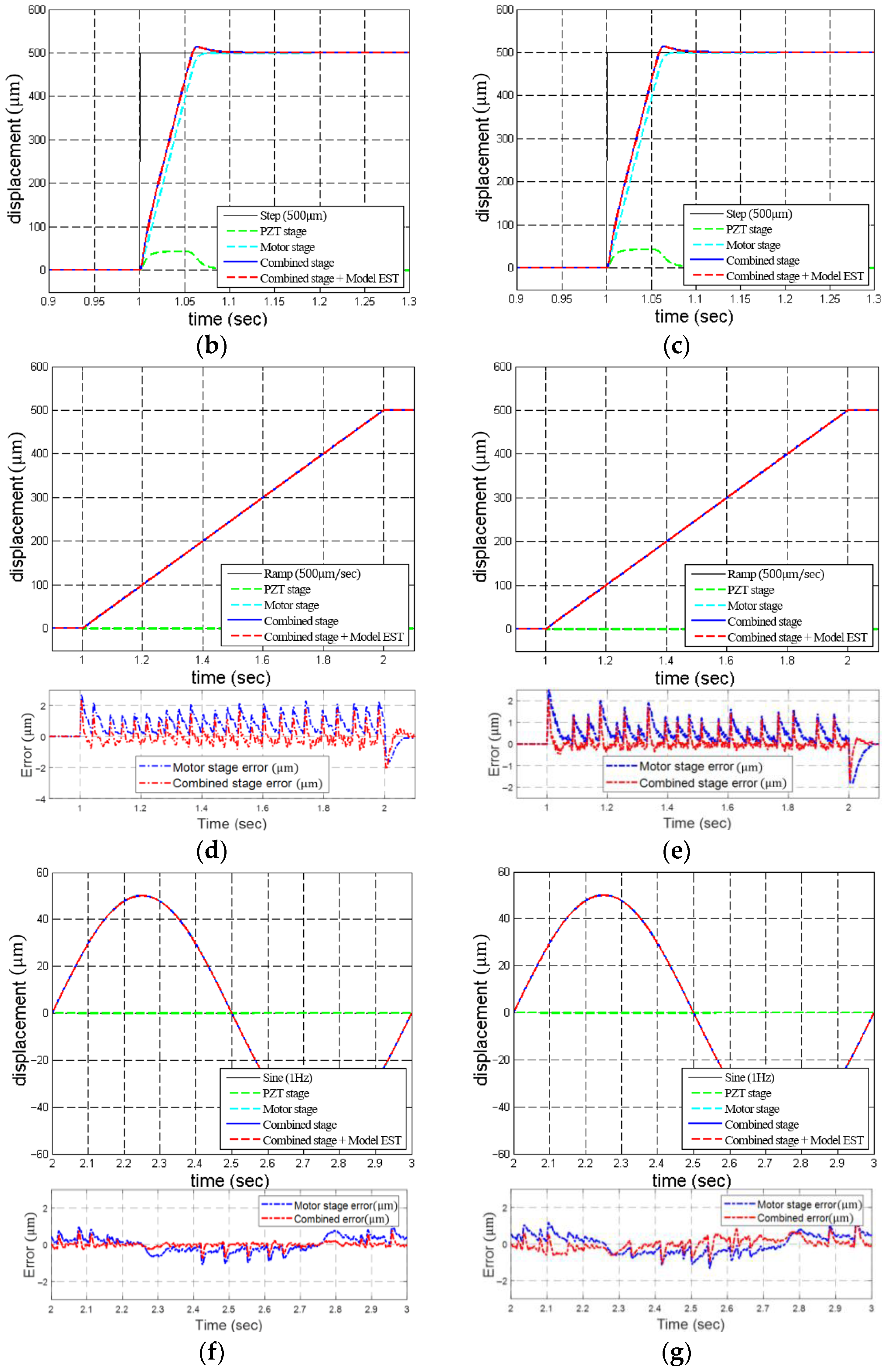
We implemented control mechanisms and conducted experiments with the following inputs: 500 μm step, 500 μm/s ramp, and 1 Hz sinusoidal signals. The responses are shown in Figure 8 and Table 3. Compared to the motor stage alone, the integrated stage with the model estimation and control switching mechanisms significantly reduced the overshoot and maximum errors. Moreover, a notable reduction in RMSE was also achieved. For example, compared with the multiple-switching control developed in [13], the proposed multiple control mechanisms improve the RMSE from 150.2 μm to 73.40 μm in the 500 μm step responses. Although the motor stage was equipped with a feedforward controller, noticeable tracking errors occurred during high-speed sinusoidal motion when using the motor stage alone. By incorporating the PZT stage for real-time error compensation, the integrated system was able to reduce tracking errors further. For instance, the PZT stages improved the tracking errors from 41% to 95%.

6. Micro-Lens Fabrication

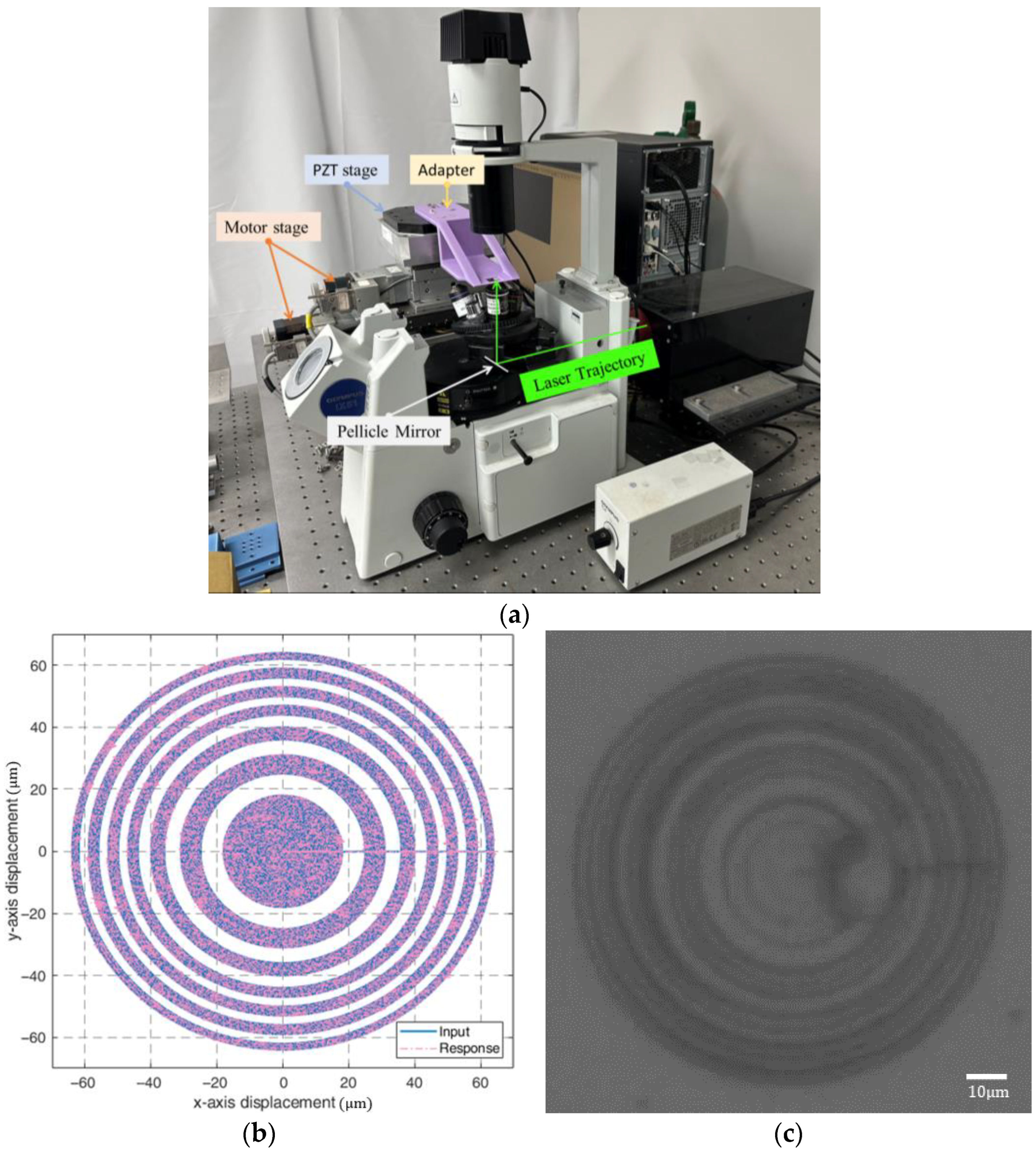
This section applies the combined stage to manufacture micro-lenses using a TPP system, which applies two-photon absorption (TPA) techniques and has been widely applied in micro-nano photonics [27,28] and micro-electromechanical systems [29,30]. The TPP system was integrated with the long-travel precision stage, as illustrated in Figure 9a, to fabricate micro-lenses. The mirror reflected the laser to focus into the resin on a microscope slide on the adapter attached to the PZT stage to manufacture micro-lenses by hardening the resin. The specially formulated resin is a blend of OrmoComp and photo-initiator for polymerization.
We fabricated a Fresnel Zone Plate (FZP), which focuses light using a planar micro-lens, with a diameter of 106 μm, with the following [14]:
r n = n f λ + 1 4 n 2 λ 2 1 / 2
as shown in Figure 9b, where r n is the radius of circle n, f is the focal length, while λ is the wavelength. We set the number of zones as n = 9, f = 500 μm, and λ = 632.8   nm . The fabricated micro-lens is shown in Figure 9c.
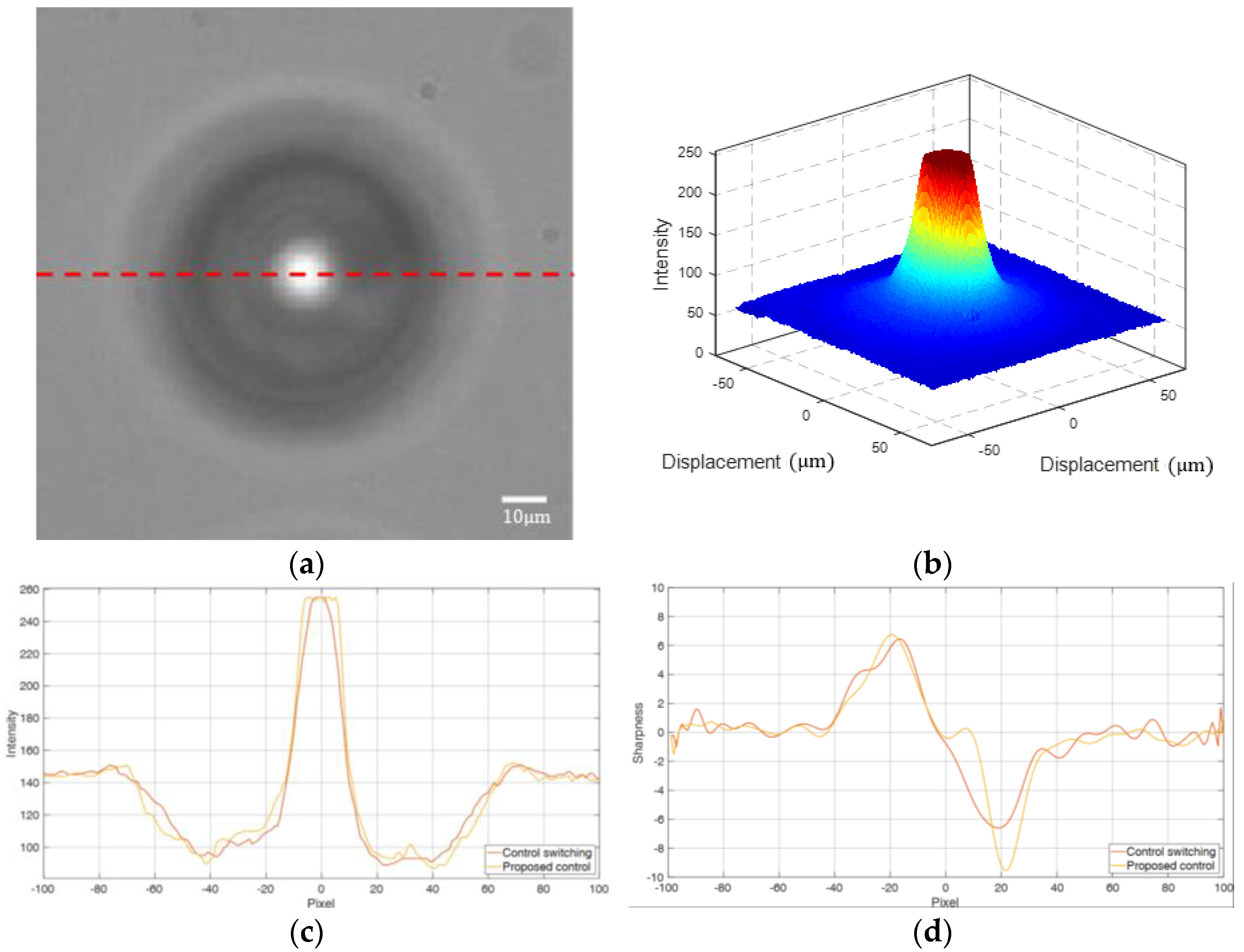
We used each micro-lens to focus light on the focal plane of a camera and assessed its optical quality based on the image intensity and sharpness, as illustrated in Figure 10a. Each captured image was converted to grayscale, where the brightness of each pixel was labeled between 0 and 255, where 0 represents completely black and 255 represents completely white, as shown in Figure 10b. The brightness on the dashed line is shown in Figure 10c, where intensity is defined as the corresponding grayscale value on each pixel, while sharpness is the derivative of the intensity (see Figure 10d).
The stage’s tracking errors and the micro-lenses’ optical properties are illustrated in Table 4. Compared with the micro-lenses fabricated in [31], which had a maximum intensity of 160, the multiple-switching mechanism in [14] improved the maximum intensity to 255 with a maximum sharpness of 6.6. In addition, the proposed multiple control mechanisms slightly reduced the RMSE from 94.2 nm to 92.5 nm and significantly increased the maximum sharpness to 9.5. These results confirm the merits of the multiple control mechanisms for enhancing the microfabrication precision.

7. Conclusions

In this study, we developed multiple control mechanisms for a precision long-travel stage consisting of a PZT and motor stages. The former used the control switching and model estimation mechanisms, while the latter utilized the gain scheduling and feedforward controls. Ultimately, the integrated stage enabled long travel with precision positioning. We implemented this multiple control strategy in a combined stage and demonstrated its effectiveness in enhancing precision positioning in simulations and experiments. Finally, we applied the long-travel precision stage to fabricate micro-lenses using TPP and demonstrated the advantages of the control mechanisms in microfabrication processes by evaluating the lenses’ optical characteristics.

Author Contributions

Conceptualization, F.-C.W. and J.-Y.Y.; methodology, F.-C.W.; software, MATLAB R2024a; Y.-T.C. and M.-H.C.; validation, F.-C.W., Y.-T.C. and M.-H.C.; formal analysis, Y.-T.C. and M.-H.C.; investigation, F.-C.W., Y.-T.C. and M.-H.C.; resources, F.-C.W., T.-T.C. and J.-Y.Y.; data curation, Y.-T.C., M.-H.C. and B.-X.Z.; writing—original draft preparation, F.-C.W., Y.-T.C. and M.-H.C.; writing—review and editing, F.-C.W., Y.-T.C., M.-H.C. and B.-X.Z.; visualization, Y.-T.C. and M.-H.C.; supervision, F.-C.W. and J.-Y.Y.; project administration, F.-C.W. and J.-Y.Y.; funding acquisition, F.-C.W. and J.-Y.Y. All authors have read and agreed to the published version of the manuscript.

Funding

This study was supported by the Ministry of Science and Technology of Taiwan (MOST 111-2221-E-002-190-MY3) and the National Science and Technology Council of Taiwan (NSTC 114-2221-E-002 -178 -MY2).

Data Availability Statement

The original contributions presented in this study are included in the article. Further inquiries can be directed to the corresponding author.

Acknowledgments

The authors appreciate Professor Chih-Lang Lin for helping with the TPP experiments.

Conflicts of Interest

The authors declare no conflicts of interest.

Appendix A. Stage Specifications

The system specifications are available at https://reurl.cc/mYxOOV (accessed on 29 August 2025).

Appendix B. Stage Models

The system models are available at https://reurl.cc/NxYM75 (accessed on 29 August 2025).

Appendix C. Modified Controllers

The modified controllers are available at https://reurl.cc/NxYMvq (accessed on 29 August 2025).

References

  1. Chen, J.; Peng, G.; Hu, H.; Ning, J. Dynamic hysteresis model and control methodology for force output using piezoelectric actuator driving. IEEE Access 2020, 8, 205136–205147. [Google Scholar] [CrossRef]
  2. Baziyad, A.G.; Ahmad, I.; Salamah, Y.B. Precision motion control of a piezoelectric actuator via a modified Preisach hysteresis model and two-degree-of-freedom H-Infinity robust control. Micromachines 2023, 14, 1208. [Google Scholar] [CrossRef]
  3. Keshavarzpour, H.; Ghasemi, A. Hybrid fuzzy PID sound radiation control of a functionally graded porous GPL-reinforced plate with piezoelectric sensor and actuator layers. Appl. Math. Modell 2024, 127, 655–678. [Google Scholar] [CrossRef]
  4. McCartney, L.N.; Crocker, L.E.; Wright, L.; Rungger, I. A Compact Device Model for a Piezoelectric Nano-Transistor. Micromachines 2025, 16, 114. [Google Scholar] [CrossRef] [PubMed]
  5. Kim, J.J.; Choi, Y.M.; Gweon, D.G. A novel mode switching control for fast settling and high precision positioning. In Proceedings of the 2007 International Conference on Control, Automation and Systems, Seoul, Republic of Korea, 17–20 October 2007. [Google Scholar] [CrossRef]
  6. Bashash, S.; Saeidpourazar, R.; Jalili, N. Tracking control of time-varying discontinuous trajectories with application to probe-based imaging and nanopositioning. In Proceedings of the 2009 American Control Conference, St. Louis, MO, USA, 10–12 June 2009. [Google Scholar] [CrossRef]
  7. Li, S.; Xu, Y.; Zhang, W.; Zou, J. A novel two-phase mode switching control strategy for PMSM position servo systems with fast-response and high-precision. IEEE Trans. Power Electron. 2022, 38, 803–815. [Google Scholar] [CrossRef]
  8. Artetxe, E.; Barambones, O.; Calvo, I.; Del Rio, A.; Uralde, J. Combined control for a piezoelectric actuator using a feed-forward neural network and feedback integral fast terminal sliding mode control. Micromachines 2024, 15, 757. [Google Scholar] [CrossRef]
  9. Wang, F.C.; Chen, Y.Y.; Wang, K.A.; Chung, T.T. The development of a long-stroke precision positioning stage for micro fabrication by two-photon polymerization. J. Laser Micro/Nanoeng. 2016, 11, 1–12. [Google Scholar] [CrossRef]
  10. Zhang, Z.; Yan, P. Enhanced robust nanopositioning control for an XY piezoelectric stage with sensor delays: An infinite dimensional H optimization approach. Mechatronics 2021, 75, 102511. [Google Scholar] [CrossRef]
  11. Makarem, S.; Delibas, B.; Koc, B. Data-driven tuning of PID controlled piezoelectric ultrasonic motor. Actuators 2021, 10, 148. [Google Scholar] [CrossRef]
  12. Wang, F.C.; Peng, Y.K.; Lu, J.F.; Chung, T.T.; Yen, J.Y. Micro-lens fabrication by a long-stroke precision stage with switching control based on model response prediction. Microsyst. Technol. 2022, 28, 45–58. [Google Scholar] [CrossRef]
  13. Wang, F.C.; Lu, J.F.; Su, W.J.; Yen, J.Y. Precision positioning control of a long-stroke stage employing multiple switching control. Microsyst. Technol. 2022, 28, 319–332. [Google Scholar] [CrossRef]
  14. Wang, F.C.; Lu, J.F.; Chung, T.T.; Yen, J.Y. Iterative parameter optimization for multiple switching control applied to a precision stage for microfabrication. Machines 2021, 9, 153. [Google Scholar] [CrossRef]
  15. Smith, R.S.; Abdalmoaty, M.; Yin, M. Optimal data-driven prediction and predictive control using signal matrix models. In Proceedings of the 2024 IEEE 63rd Conference on Decision and Control (CDC), Milan, Italy, 16–19 December 2024. [Google Scholar] [CrossRef]
  16. Hiraoka, K.; Koiwai, K.; Yamamoto, T. Design of a Database-Driven PID Controller Using Response Prediction for Unknown Time-delay Systems. IEEJ Trans. Electron. Inf. Syst. 2023, 143, 345–352. [Google Scholar] [CrossRef]
  17. Multi-Axis Piezo Scanner High Dynamics Nanopositioner/Scanner with Direct Position Measuring. Available online: https://reurl.cc/Om69QA (accessed on 29 August 2025).
  18. X Stage, ALS-510-HP, Chuo Precision Industrial Co. Ltd. Available online: https://reurl.cc/2Qapv4 (accessed on 29 August 2025).
  19. Z Lift Stage, ALV-104-HP, Chuo Precision Industrial Co. Ltd. Available online: https://reurl.cc/yAOzGE (accessed on 29 August 2025).
  20. Wang, F.C.; Wang, K.A.; Chen, Y.Y.; Chen, H.J.; Yen, J.Y. Impacts of sensor layouts on the performance of a long-stroke nano-positioning stage. Adv. Mech. Eng. 2016, 8, 1–16. [Google Scholar] [CrossRef]
  21. Glover, K.; McFarlane, D. Robust stabilization of normalized coprime factor plant descriptions with H-bounded uncertainty. IEEE Trans. Autom. Control 1989, 34, 821–830. [Google Scholar] [CrossRef]
  22. Georgiou, T.T.; Smith, M.C. Optimal robustness in the gap metric. IEEE Trans. Autom. Control 1990, 35, 673–686. [Google Scholar] [CrossRef]
  23. Zhou, K.; Doyle, J.C. Essentials of Robust Control; Prentice-Hall: Upper Saddle River, NJ, USA, 1998. [Google Scholar]
  24. McFarlane, D.; Glover, K. A loop-shaping design procedure using H synthesis. IEEE Trans. Autom. Control 1992, 37, 759–769. [Google Scholar] [CrossRef]
  25. Wang, F.C.; Chen, L.S.; Tsai, Y.C.; Hsieh, C.H.; Yen, J.Y. Robust loop-shaping control for a nano-positioning stage. J. Vib. Control 2014, 20, 885–900. [Google Scholar] [CrossRef]
  26. Kennedy, J.; Eberhart, R. Particle swarm optimization. In Proceedings of the ICNN’95-International Conference on Neural Networks, Perth, WA, Australia, 27 November–1 December 1995. [Google Scholar] [CrossRef]
  27. Sun, H.B.; Matsuo, S.; Misawa, H. Three-dimensional photonic crystal structures achieved with two-photon-absorption photopolymerization of resin. Appl. Phys. Lett. 1999, 74, 786–788. [Google Scholar] [CrossRef]
  28. Scrimgeour, J.; Sharp, D.N.; Blanford, C.F.; Roche, O.M.; Denning, R.G.; Turberfield, A.J. Three-Dimensional Optical Lithography for Photonic Microstructures. Adv. Mater. 2006, 18, 1557–1560. [Google Scholar] [CrossRef]
  29. Sun, Z.B.; Dong, X.Z.; Chen, W.Q.; Nakanishi, S.; Duan, X.M.; Kawata, S. Multicolor polymer nanocomposites: In situ synthesis and fabrication of 3D microstructures. Adv. Mater. 2008, 20, 914–919. [Google Scholar] [CrossRef]
  30. Wang, W.K.; Sun, Z.B.; Zheng, M.L.; Dong, X.Z.; Zhao, Z.S.; Duan, X.M. Magnetic nickel–phosphorus/polymer composite and remotely driven three-dimensional micromachine fabricated by nanoplating and two-photon polymerization. J. Phys. Chem. C 2011, 115, 11275–11281. [Google Scholar] [CrossRef]
  31. Wang, F.C.; Wang, K.A.; Chung, T.T.; Yen, J.Y. Fabrication of large-scale micro-structures by two-photon polymerization with a long-stroke precision stage. Adv. Mech. Eng. 2017, 9, 1687814017695757. [Google Scholar] [CrossRef]
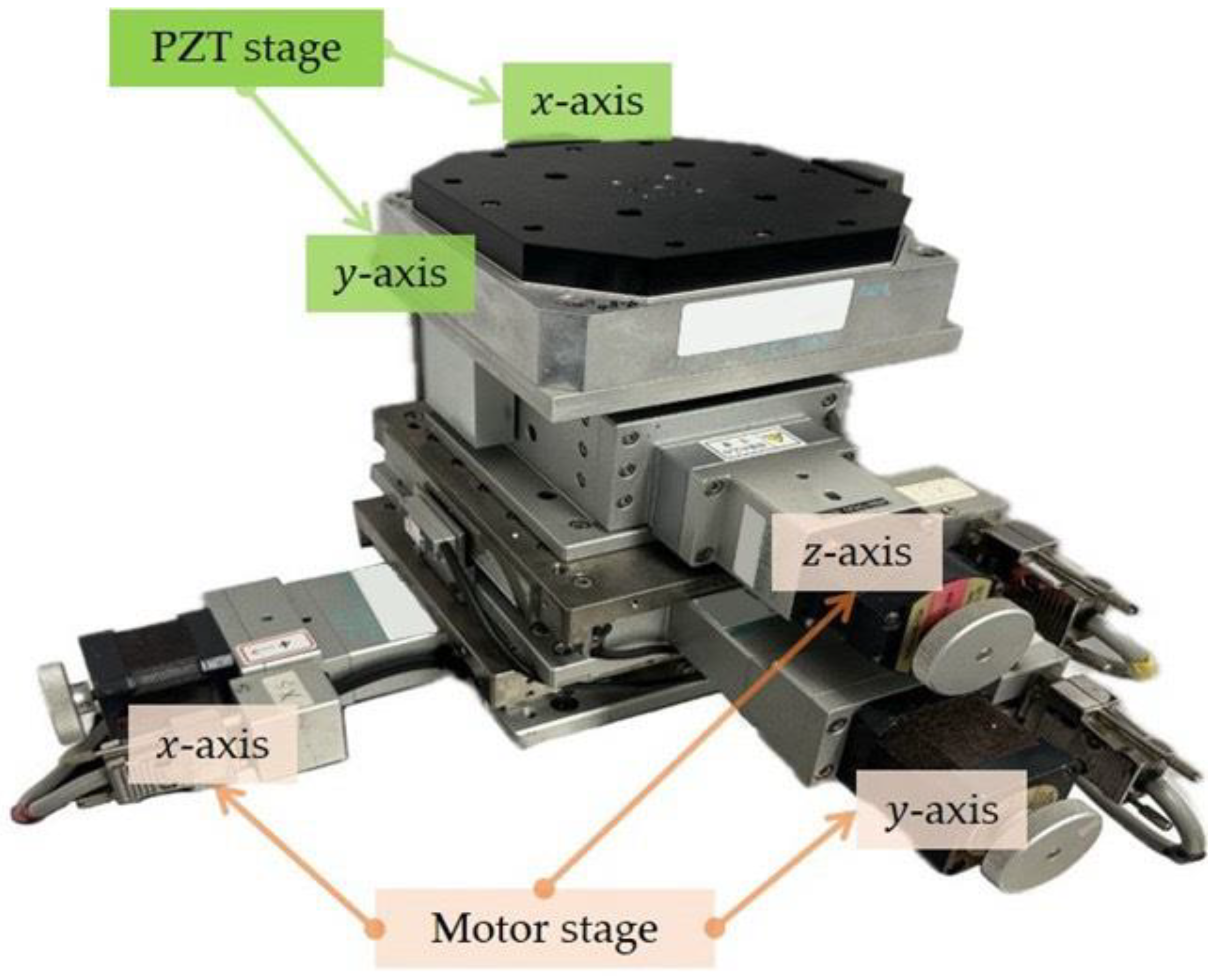
Figure 1. The precision long-travel stage.
Micromachines 16 01105 g001
Figure 2. Derivation of stage models: (a) PZT stage; (b) motor stage.
Micromachines 16 01105 g002
Figure 3. Model estimation and control switching for the PZT stage.
Micromachines 16 01105 g003
Figure 4. Loop shaping.
Micromachines 16 01105 g004
Figure 5. Response comparison with robust and robust PI controls: (a) x-axis; (b) y-axis.
Micromachines 16 01105 g005
Figure 6. Multiple-switching control mechanism.
Micromachines 16 01105 g006
Figure 7. Motor stage control: (a) the block diagram; (b) gain scheduling; (c) Bode plots; (d) response to a ramp input; (e) response to a sinusoidal input.
Micromachines 16 01105 g007
Figure 8. Combined stage control: (a) block diagram; (b) x-axial step response; (c) y-axial step response; (d) x-axial ramp response; (e) y-axial ramp response; (f) x-axial sinusoidal response; (g) y-axial sinusoidal response (y-axis).
Micromachines 16 01105 g008aMicromachines 16 01105 g008b
Figure 9. Micro-lens fabrication: (a) system integration; (b) FZP design; and (c) the micro-lens.
Micromachines 16 01105 g009
Figure 10. FZP: (a) focal plane; (b) image brightness; (c) the intensity curves; and (d) the sharpness curves.
Micromachines 16 01105 g010
Table 1. Tracking performance of the PZT stage (step responses).
C.S. [14]Proposed ControlImp. (%)
x-axisSimulationOvershoot (%)3.97861.805154.63
RMSE (μm)1.69491.51261.08
Settling time (s)1.02911.01141.72
Rising time (s)0.00610.0064−4.92
ExperimentOvershoot (%)8.91003.920056.00
RMSE (μm)1.45501.40923.15
Settling time (s)1.07121.05031.96
Rising time (s)0.00660.0069−4.55
y-axisSimulationOvershoot (%)3.75251.758553.14
RMSE (μm)1.48161.46810.91
Settling time (s)1.07891.01176.23
Rising time (s)0.00600.0065−8.33
ExperimentOvershoot (%)2.25221.510432.90
RMSE (μm)1.48481.46721.20
Settling time (s)1.02071.01150.90
Rising time (s)0.00640.0066−3.13
C.S.: control switching; imp. (%): percentage improvement.
Table 2. Performance: motor stage.
Ramp Input
(500 μm/s)
Sinusoidal Input
(5 Hz)
SimulationPhase lag (deg)-2.4000
MAE (μm)1.66183.6400
RMSE (μm)0.19982.5352
ExperimentPhase lag (deg)-3.6000
MAE (μm)3.00004.7922
RMSE (μm)0.91224.1897
MAE: maximum absolute error.
Table 3. Experimental data analysis.
x-Axisy-Axis
Motor StageCombined StageMotor
Stage
Combined Stage
StepRising time (s)0.04870.04520.05010.0487
Settling time (s)1.06741.06391.08521.0831
Overshoot (%)01.520001.4191
RMSE (μm)76.395176.382287.424987.4209
RampMAE (μm)2.50002.40002.90002.9000
RMSE (μm)0.78510.39580.91220.5301
SinusoidalGain (dB)0.22290.01150.30720.0454
MAE (μm)3.60000.78493.00000.9755
Phase lag (μm)4.79221.43905.54601.4162
RMSE (μm)4.18970.16874.04520.3321
MAE: maximum absolute error.
Table 4. FZP performance.
C.S. [14]Proposed Control
RMSE (nm)94.292.5
Maximum Intensity255255
Maximum Sharpness6.69.5
C.S.: control switching.
Disclaimer/Publisher’s Note: The statements, opinions and data contained in all publications are solely those of the individual author(s) and contributor(s) and not of MDPI and/or the editor(s). MDPI and/or the editor(s) disclaim responsibility for any injury to people or property resulting from any ideas, methods, instructions or products referred to in the content.