Communication

A Low-Profile Dielectric Resonator Filter with Wide Stopband for High Integration on PCB

1
School of Information Science and Technology, Nantong University, Nantong 226019, China
2
Research Center for Intelligent Information Technology, Nantong University, Nantong 226019, China
3
Nantong Key Laboratory of Advanced Microwave Technology, Nantong University, Nantong 226019, China
*
Author to whom correspondence should be addressed.
Micromachines 2023, 14(9), 1803; https://doi.org/10.3390/mi14091803
Submission received: 28 August 2023 / Revised: 20 September 2023 / Accepted: 20 September 2023 / Published: 21 September 2023

Abstract

:
A low-profile dielectric resonator (DR) filter is proposed to achieve the feature of high integration and wide stopband. The high integration is due to the structure of printed circuit board (PCB) substrate instead of metal cavity, which can be easily integrated with other planar circuits. Thus, the proposed design can improve the integration level and reduce installation errors. Moreover, the out-of-band harmonics can be well suppressed by the structure combined with introducing rectangular hollowing in the center of the dielectric block, coupling the feed and loading 1/4λ wavelength branch. For demonstration, it is fabricated and measured. The simulated and experimental results with good agreement are presented, the insertion loss is as low as 1.1 dB, the profile height is only 0.77λg, and the stopband reaches 2.61f0.

1. Introduction

Dielectric resonator (DR) [1,2,3,4,5,6,7] filters have become a research hotspot in recent years due to their superior characteristics such as high Q value, low manufacturing cost, temperature stability, miniaturization, and compatibility with microwave circuits. The wide stopband filter [8,9,10,11,12] has also been widely used in microwave systems because of its good harmonic suppression level, which can meet the out-of-band requirements.
With the rapid growth of communication, various approaches have been reported to achieve wide stopband DR filters. The first method is to use the balanced structure of the dielectric resonator filter to suppress harmonics [13,14], because differential feeding itself is a mode selection, but the differential feeding will produce a common mode response, and the early appearance of common mode is the main reason for inhibiting wide stopband. The second method [15,16,17] is to combine two different modes of dielectric resonators, which can significantly improve the spurious performance. However, due to the combination of two different types of resonators, the filter size is too large and the structure is complex. In order to avoid the above problems, the third method [18,19,20,21] starts from the resonator itself and introduces a cylindrical hole in the center of the dielectric resonator to improve the separation between the dominant mode and the higher-order mode, but the stopband bandwidth expansion is limited.
In this letter, a low-profile DR filter with a wide stopband as shown in Figure 1 is proposed, which uses a substrate instead of the traditional metal cavity structure to reduce the profile height and improve the integration. Benefiting from the structure of the coupled feeding, not only are some unnecessary modes filtered, but also the direct contact between the feed structure and the dielectric block is avoided, and the assembly error is reduced. More importantly, the low frequency harmonic mode of the dielectric resonator is suppressed by digging a rectangular groove in the center of the dielectric block, and the high frequency harmonic mode is suppressed by the structure of loading branches. Finally, the excellent suppression level of the filter is achieved. For demonstration, a DR filter with a wide stopband is designed and fabricated.

2. Proposed Low-Profile Dielectric Resonator Filter with Wide Stopband

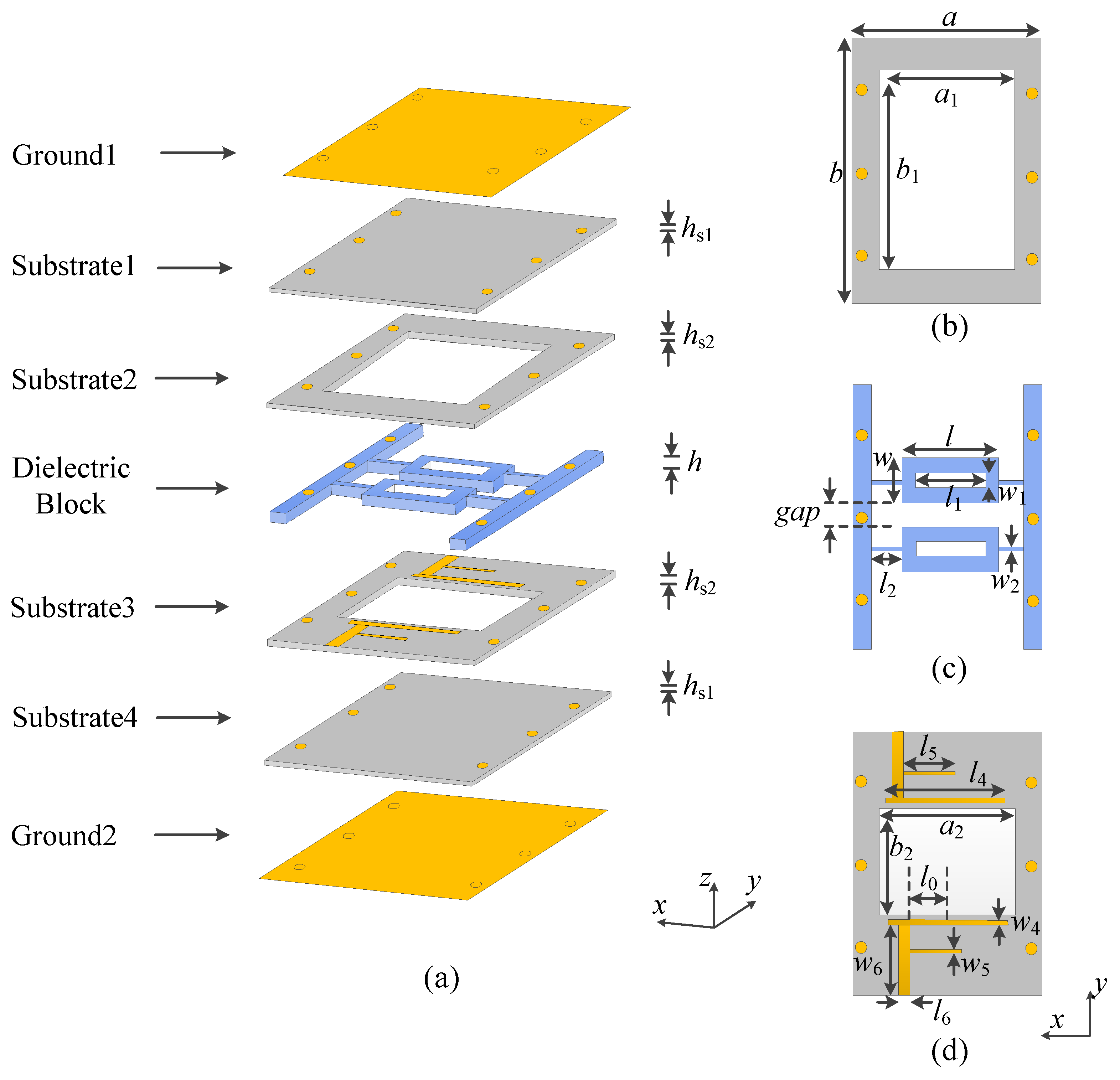
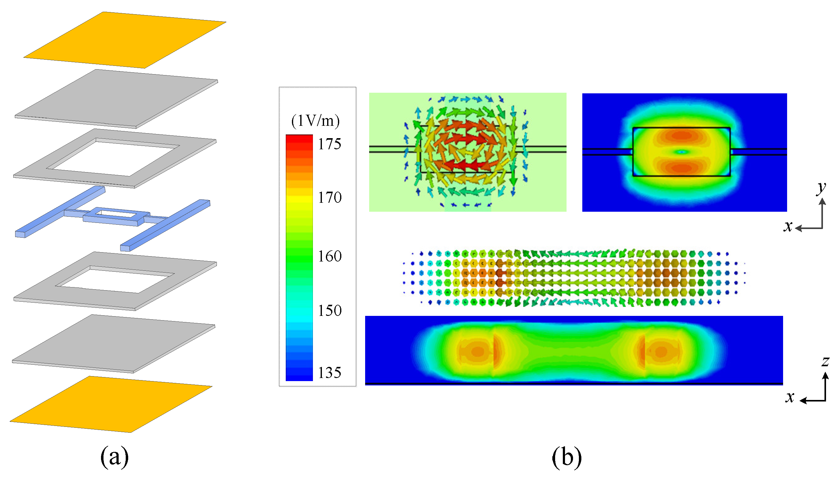
2.1. Methodology and DR Filter Design

Figure 1 exhibits the structure composition of the proposed low-profile dielectric resonator with a wide stopband. The top and bottom are metal layers, with four substrate layers and a dielectric layer stacked in the middle. Substrates 1, 2, 3 and 4 are Rogers 4003C (dielectric constant εr = 3.38 and loss tangent of 0.0027) with thicknesses of 0.203, 0.813, 0.203, and 0.813 mm, respectively. Substrates 2 and 3 are hollowed with air cavities to reduce the dielectric loss and enhance the quality factor. The air cavity of substrate 3 is smaller than substrate 2, because metal feeders are printed on substrate 3. Substrates 1 and 4 are both complete substrates, which are used to print the complete metal ground. The media block layer consists of two main rectangular dielectric blocks, four connecting strips and fixed strips on both sides, with dielectric constant εr = 89.5 and a loss tangent of 0.0006.
The input/output coupled lines and the feed lines are implemented on substrate 3 as shown in Figure 1d, allowing for transmission between signals. The top and bottom metal layers of the substrate are connected through metal vias, so that the whole circuit can be packaged. Each dielectric block has a rectangular hollow in the center, which can suppress harmonics. The software for full-wave simulation is Computer Simulation Technology (CST).
The simplified model in Figure 2a is used to analyze the proposed DR, where the dielectric block layer consists of a rectangular block (a × b × h), two connecting strips and two fixed strips with two layers of dielectric substrate and metal layer on the top and bottom, respectively. Figure 2b shows the working mode ( T E 11 δ z mode) of the proposed DR. It can be seen that the strong electric field of the mode is concentrated above and below the center symmetry, and it is distributed in a circular pattern. For the T E 11 δ z  mode, there is no electric field passing through the z direction, thus it can be named as TEz mode. Additionally, 1, 1 and δ mean the number of half-wavelength distribution, where 0 < δ < 1.
According to Helmholtz equation and boundary conditions, the EM field expressions of T E 11 δ z mode can be presented as follows:
k x = m π l , k y = n π w
ε r e f f = [ ( ε r 1 × t ) + ( ε r 2 × h ) ] / ( t + h )
h r e f f = h + t
k x 2 + k y 2 α z 2 = k 0 2
k x 2 + α z 2 = ( ε r e f f 1 ) k 0 2
f 0 = c 2 π ε r e f f k x 2 + k y 2 + k z 2
where εreff is the effective dielectric constant, hreff is the effective height, k0 is the wavenumber at operation frequency, εr is the relative permittivity of the DR, and kx, ky, kz are the wavenumber in the three directions of x, y, z.
Figure 3 exhibits how the variation of resonant simulation frequency and theoretical frequency of T E 11 δ z mode in DR vary with a, b and h. It can be seen that the resonant frequencies of simulation and theoretical values of T E 11 δ z mode are in good agreement. It can be found that with the increase in a, b and h, the simulation and theoretical frequencies are decreasing.
The coupling topology of the proposed DR filter with wide stopband is given in Figure 4, where the S and L represent the source and the load, respectively. Owing to its symmetric configuration, the coupling factors satisfy the relationship of MS1 = M2L, and MS2 = M2L, where M is the coupling between different elements in the coupling matrix. Here, 1 and 2 represent the first resonator and the second resonator, respectively.
For demonstration, a low-profile DR filter with wide stopband is designed. We assume that the order n is equal to 2. According to the proposed filter design index, we can calculate the lumped element values in the low-pass prototype filter, and the results are as follows: g0 = l, g1 = 0.8431 and g2 = 0.6220 [22]. Therefore, the coupling coefficient k12 and external quality factor Qe required by the filter design can be calculated by the following formula [22]:
k 1 A 1 B = F B W L g 1 g 2 = 0.00713
Q e 1 = g 1 g 2 F B W L = 163 . 27
Assuming filter with the center frequency of f0 = 4.97 GHz and the 3-dB fractional bandwidth (FBW) of 0.99%, the coupling matrix M can be written as
M = S 1 2 L S 0 0.8163 0.0151 0.0008 1 0.8163 0 0.7625 0.0151 2 0.0151 0.7625 0 0.8163 L 0.0008 0.0151 0.8163 0
Figure 4b shows the theoretical response resulting from the coupling matrix, it can be found that the theoretical response matches well with the simulated one.
The required external quality factor and coupling coefficients can be calculated from the lowpass prototype parameters. As a result, the desired Qe = 163.27 and k12 = 0.00713 are obtained, which are used for determining the main coupling. In this design, Qe is mainly controlled by the position of the tapping point l0, while k12 is determined by the coupling space gap, as shown in Figure 5a and Figure 5b, respectively.

2.2. Parametric Study and Performance Analysis

To clear the performance variation of the proposed design, Figure 6 exhibits the effects of different parameters (l0 and gap). Figure 6a shows that the impedance matching changes with the change of l0, because the feeding position affects the external quality factor. As can be seen from Figure 6b, as the gap increases, the coupling between the two DRS becomes weaker and the bandwidth decreases. In addition, the impedance matching first becomes better and then worse.
In order to meet the requirements of the filter on the out-of-band harmonic suppression level, this design adopts the structure of the combination of three methods. As shown in Figure 7a, the structure is realized by using the resonator without loading rectangular slots and directly feeding. It can be seen from the corresponding response diagram on the right that there are more harmonics in the low and high frequency bands of the structure, and the out-of-band response is poor. The structure shown in Figure 7b is realized by loading the rectangular slot resonator combined with direct feeding. It can be seen from the response diagram that the structure effectively inhibits some harmonics at the low frequency band. By introducing rectangular hollowing in the center of the dielectric block, the modes with strong electric field distributions in the center of the dielectric block can be suppressed effectively. It can be seen from Figure 7a,b that a mode (TEy 111 mode) located at 5 GHz is suppressed by hollowing the rectangular slot in the center of the dielectric block.
The structure shown in Figure 7c is realized by loading a rectangular slot resonator combined with coupling feeding. Compared with direct feeding, the structure can suppress multiple harmonics in the band, and the coupling feed will not let the feeder make contact with the medium block directly, which is helpful to reduce the subsequent assembly error. Finally, Figure 7d shows the structure of loading a 1/4 wavelength branch, which can effectively suppress harmonics in high frequency bands. Therefore, the structure combined with these three methods can effectively solve the problem of poor out-of-band performance of the filter and improve the stopband performance.

2.3. Design Procedure

The design procedure of the proposed DR filter can be simply summarized as follows:
(i)
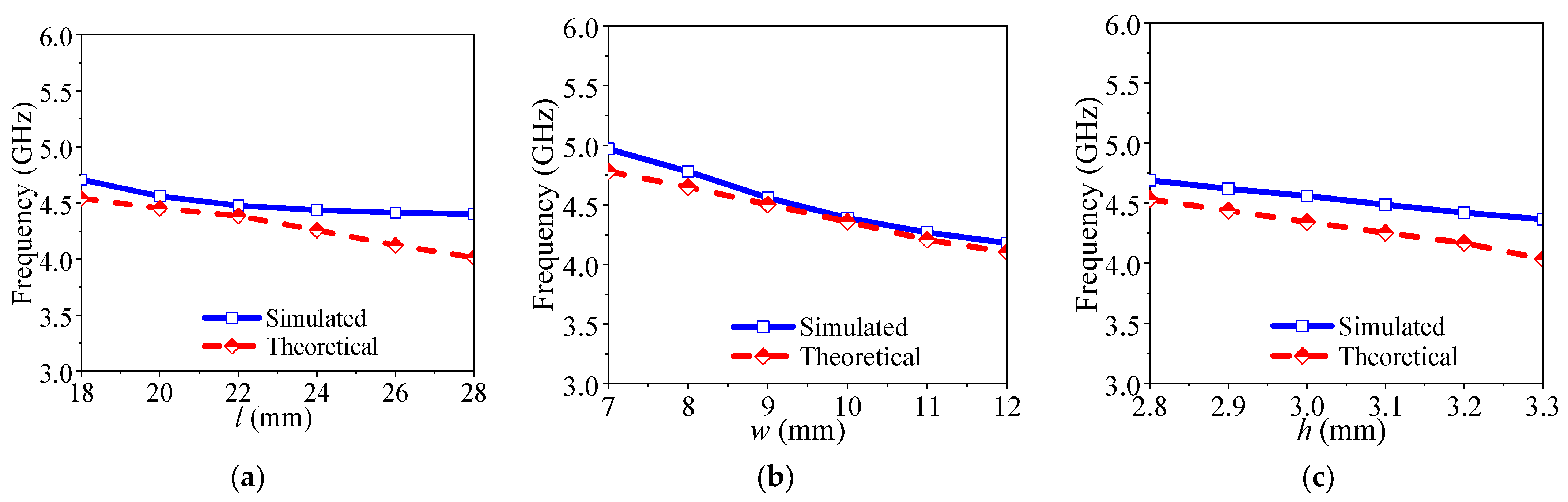
Obtain the dimensions of the high integrated dielectric resonators according to the desired center frequency from the resonant mode frequency variation.
(ii)
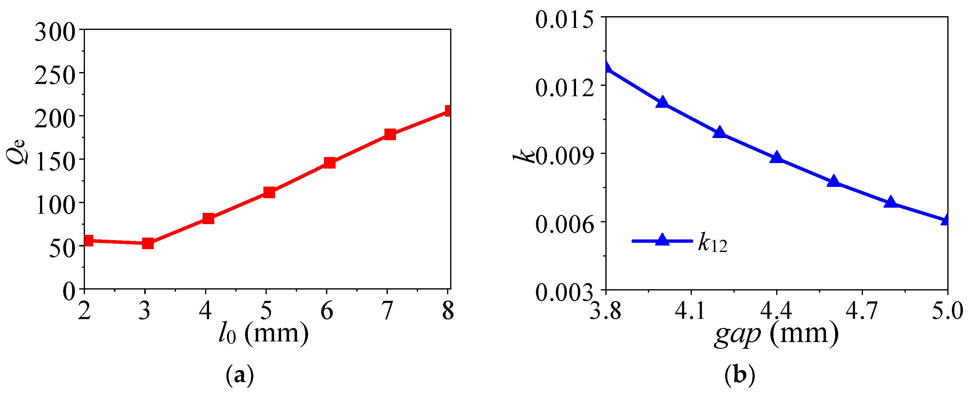
Achieve l0 according to the coupling matrix and impedance matching parametric study in Figure 6a.
(iii)
Obtain gap according to the coupling matrix and bandwidth parametric study in Figure 6b.
(iv)
Optimize the performance and obtain the final dimensions in CST.
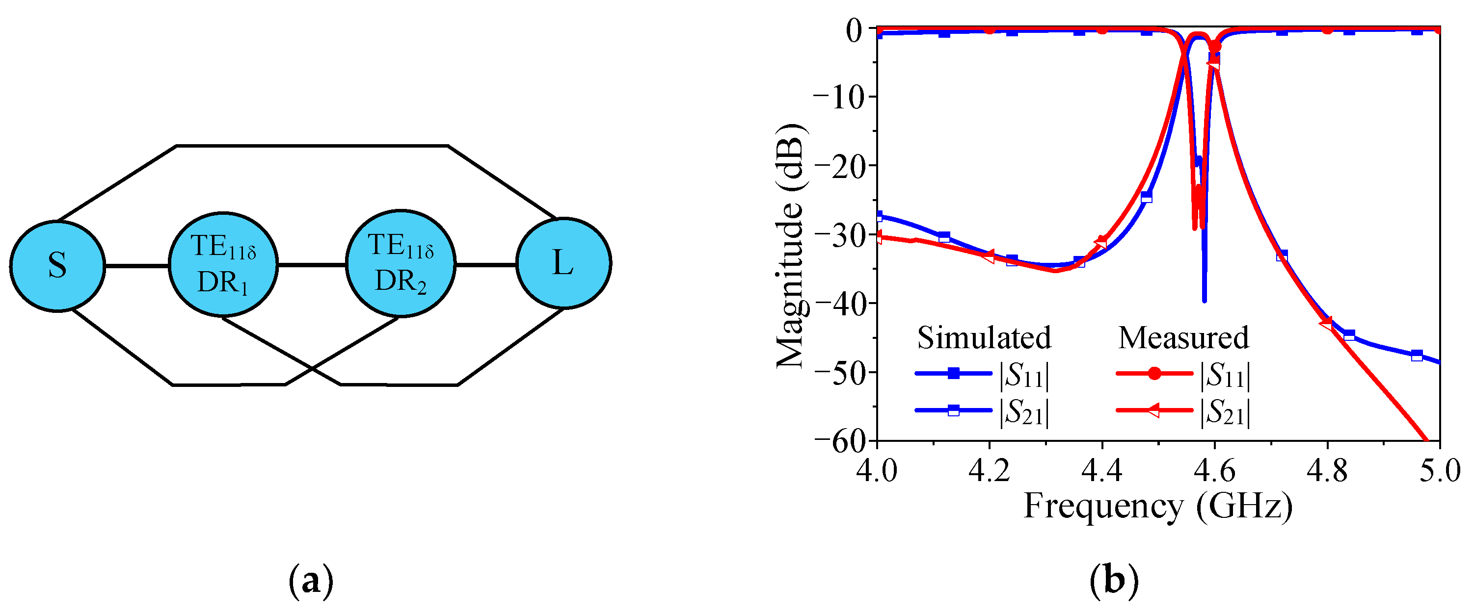
3. Results

A prototype of the proposed low-profile DR filter is demonstrated. The detailed dimensions are shown as follows: a = 50 mm, b = 50 mm, a1 = 4 mm, b1 = 40 mm, a2 = 35 mm, b2 = 30 mm, l = 18 mm, w = 9 mm, l1 = 14 mm, w1 = 3 mm, l2 = 12 mm, w2 = 1 mm, w3 = 2 mm, l4 = 18 mm, w4 = 0.5 mm, l5 = 7 mm, w5 = 0.3 mm, l6 = 7 m, w6 = 1.8 mm, h = 3.1 mm, hs1 = 0.203 mm, hs2 = 0.813 mm. Figure 8 shows photos of the prototype, simulations, and measurements by the Keysight N5230C vector network analyzer (Santa Rosa, CA, USA). Among them, Substrates 1 and 2 (Substrates 3 and 4) are integrated and processed together during the fabrication processing through one prepreg layer with the thickness of 0.1 mm, dielectric constant of 3.38 and loss tangent of 0.0027, while the dielectric block is fabricated separately. Then, assemble them together by using metal screws. The limitation of this kind of assembly method is composed of two parts. Firstly, the tightening of assembly metal screws cannot be guaranteed, which will reduce the unloaded quality factor of the dielectric resonator and thus increase the loss of the filter. Secondly, the deviation in the relative position of the substrates and the dielectric block cannot be avoided, thus the impedance matching can be influenced and changes the bandwidth accordingly.
Figure 9 exhibits that the simulated minimum insertion loss is about 1.23 dB at 4.57 GHz, the simulated 3-dB bandwidth is about 1.05%, and the simulated harmonic suppression is about 2.62f0. The measured minimum insertion loss is about 1.29 dB with the center frequency of 4.57 GHz, the measured 3-dB FBW of 0.99% and the harmonic suppression reaches 2.61f0. The deviation between the simulated and measured results is due to the fabricated error, assembly error and the measured error.
Table 1 lists the performance and state-of-the-art design of this work. Compared with existing dielectric resonator filters with wide stopbands, this design improves integration, reduces the profile, and improves the harmonic suppression level. Here, the improved integration is attributed to the PCB technology, which can be integrated with other planar circuits that were fabricated on the PCB.

4. Conclusions

A low-profile DR filter with wide stopband is proposed. By using the grounded substrate to replace the traditional metal cavity, the proposed one shows high integration with other planar circuits. Moreover, it benefited from rectangular hollowing in the center of the dielectric block, coupling feed and loading 1/4λ wavelength branch, it obtains a wider stopband than other DR filters. A prototype with high integration is fabricated at 4.57 GHz, and obtains the profile of 0.77λg and a wide stopband up to 2.61f0. Therefore, the proposed DR filter can improve the integration by sharing the same substrate with other circuits, reduce the cost, and improve the level of out-of-band harmonic suppression. It is believed that this design has broad application prospects in modern wireless communication systems.

Author Contributions

Conceptualization: L.Z. and K.X.; methodology: K.X.; software: S.L. and M.W.; validation: L.Z. and K.X.; formal analysis: L.Z. and K.X.; investigation: S.L.; resources: S.L., L.Z. and K.X.; data curation: S.L. and M.W.; writing—original draft preparation: S.L. and M.W.; writing—review and editing: L.Z. and K.X.; visualization: L.Z.; supervision: L.Z. and K.X.; project administration: L.Z. and K.X.; funding acquisition: K.X. All authors have read and agreed to the published version of the manuscript.

Funding

This work was supported by the National Natural Science Foundation of China (Grant 62201291), Natural Science Foundation of Jiangsu Province (Grant BK20200962), Nantong Science Research Project of Jiangsu Higher Education Institutions (Grant 21KJD430001), 2023 Nantong University College Student Innovation Training Program Project (Grant 2023103041066).

Data Availability Statement

The data presented in this study are available on request from the corresponding author.

Conflicts of Interest

The authors declare no conflict of interest.

References

  1. Huang, F.X.; Fouladi, S.; Mansour, R.R. High-tunable dielectric resonator filters using MEMS technology. IEEE Trans. Microw. Theory Tech. 2011, 59, 3401–3409. [Google Scholar] [CrossRef]
  2. Höft, M. Y-Shape Dielectric dual-mode resonator. IEEE Trans. Microw. Theory Tech. 2008, 56, 3066–3071. [Google Scholar] [CrossRef]
  3. Zhou, L.H.; Chen, J.X.; Xue, Q. Design of compact coaxial-like bandpass filters using dielectric-loaded strip resonator. IEEE Trans. Microw. Theory Tech. 2018, 8, 456–464. [Google Scholar] [CrossRef]
  4. Memarian, M.; Mansour, R.R. Quad-mode and dual-mode dielectric resonator filter. IEEE Trans. Microw. Theory Tech. 2009, 57, 3418–3426. [Google Scholar] [CrossRef]
  5. Zhu, Y.Y.; Li, Y.L.; Chen, J.X. A novel dielectric strip resonator filter. IEEE Microw. Wirel. Compon. Lett. 2018, 28, 591–593. [Google Scholar] [CrossRef]
  6. Meher, P.R.; Behera, B.R.; Mishra, S.K.; Althuwayb, A.A. A chronological review of circularly polarized dielectric resonator antenna: Design and developments. Int. J. RF Microw. Comput. Aided Eng. 2021, 31, e22589. [Google Scholar] [CrossRef]
  7. Meher, P.R.; Behera, B.R.; Mishra, S.K. Design and its state-of-the-art of different shaped dielectric resonator antennas at millimeter-wave frequency band. Int. J. RF Microw. Comput. Aided Eng. 2020, 30, e22221. [Google Scholar] [CrossRef]
  8. Zhu, Y.; Dong, Y. A novel compact wide-stopband filter with hybrid structure by combining SIW and microstrip technologies. IEEE Microw. Wirel. Compon. Lett. 2021, 31, 841–844. [Google Scholar] [CrossRef]
  9. Tang, C.-W.; Tseng, C.-T.; Chiu, S.-H.; Wu, P.H. Design of wide passband/stopband microstrip bandpass filters with the stepped coupled line. IEEE Trans. Microw. Theory Tech. 2013, 61, 1095–1103. [Google Scholar] [CrossRef]
  10. Azad, A.R.; Mohan, A. Substrate integrated waveguide dual-band and wide-stopband bandpass filters. IEEE Microw. Wirel. Compon. Lett. 2018, 28, 660–662. [Google Scholar] [CrossRef]
  11. Yang, M.; Wang, H.; Yang, T.; Hu, B.; Li, H.; Zhou, Y.; Li, T. Design of wide stopband for waveguide low-pass filter based on circuit and field combined analysis. IEEE Microw. Wirel. Compon. Lett. 2021, 31, 1199–1202. [Google Scholar] [CrossRef]
  12. Tang, C.W.; Hsu, Y.K. A microstrip bandpass filter with ultrawide stopband. IEEE Trans. Microw. Theory Tech. 2008, 56, 1468–1472. [Google Scholar] [CrossRef]
  13. Chen, J.X.; Zhan, Y.; Qin, W.; Bao, Z.H. Analysis and design of balanced dielectric resonator bandpass filters. IEEE Trans. Microw. Theory Tech. 2016, 64, 1476–1483. [Google Scholar] [CrossRef]
  14. Chen, J.X.; Zhan, Y.; Qin, W.; Bao, Z.H. Novel narrow-band balanced bandpass filter using rectangular dielectric resonator. IEEE Microw. Wirel. Compon. Lett. 2015, 25, 289–291. [Google Scholar] [CrossRef]
  15. Hwang, H.Y.; Park, N.S.; Cho, Y.H. The design of bandpass filters made of both dielectric and coaxial resonators. IEEE MTT-S Int. Microw. Symp. Digest. 1997, 2, 805–808. [Google Scholar]
  16. Zhang, Y.; Chen, J.X.; Qin, W.; Li, J.; Bao, Z.H. Spurious-free differential bandpass filter using hybrid dielectric and coaxial resonators. IEEE Microw. Wirel. Compon. Lett. 2016, 26, 574–576. [Google Scholar] [CrossRef]
  17. Boe, P.; Mick, D.; Kamrath, F.; Hoft, M. Hybrid inline TE/TM mode dielectric resonator filters with wide spurious free range and controllable transmission zeros. Proceeding of the 2020 50th European Microwave Conference (EuMC), Utrecht, The Netherlands, 12–14 January 2021; IEEE: Piscataway, NJ, USA, 2021; Volume 55, pp. 2168–2175. [Google Scholar]
  18. Snyder, R.V. Dielectric resonator filters with wide stopbands. IEEE Trans. Microw. Theory Tech. 1992, 40, 555–558. [Google Scholar] [CrossRef]
  19. Sun, X.G. Ring-type dielectric resonator cavity filters with wide spurious free region. IEEE Microw. Dep. Transcend Commun. Co. 2007, 66, 2105–2108. [Google Scholar]
  20. Zhang, R.; Mansour, R.R. Low-cost dielectric-resonator filters with improved spurious performance. IEEE Trans. Microw. Theory Tech. 2007, 55, 2168–2175. [Google Scholar] [CrossRef]
  21. Chu, Q.-X.; Ouyang, X.; Wang, H.; Chen, F.-C. TE01δ–mode dielectric-resonator filters witch controllable transmission zeros. IEEE Trans. Microw. Theory Tech. 2013, 61, 1086–1094. [Google Scholar] [CrossRef]
  22. Hong, J.S.; Lancaster, M.J. Microstrip Filters for RF/Microwave Applications; Wiley: New York, NY, USA, 2001; Chapters 8–10. [Google Scholar]
Figure 1. The structure of the proposed filter. (a) Three-dimensional view of the proposed DR filter. (b) Substrate 2. (c) Dielectric block. (d) Substrate 3.
Micromachines 14 01803 g001
Figure 2. (a) The simplified model of the proposed HIDR. (b) The electric field of T E 11 δ z mode.
Micromachines 14 01803 g002
Figure 3. The variations of resonant frequency for T E 11 δ z mode of the DR when changing a, b and h. (a) Different a. (b) Different b. (c) Different h.
Micromachines 14 01803 g003
Figure 4. The coupling topology and the theoretical response of the proposed design. (a) Coupling topology. (b) Theoretical and simulated response.
Micromachines 14 01803 g004
Figure 5. Extracted Qe and coupling coefficient. (a) Qe against l0. (b) k12 against gap.
Micromachines 14 01803 g005
Figure 6. Effect of different parameters on simulated performance of the proposed design. (a) Different l0. (b) Different gap.
Micromachines 14 01803 g006
Figure 7. Filter structure changes and performance response. (a) Full resonator combined with direct feed. (b) Loaded rectangular slot resonator combined with direct feed. (c) Loaded rectangular slot resonator combined with coupled feed. (d) Loaded rectangular slot resonator combined with coupled feed and 1/4 wavelength branch.
Micromachines 14 01803 g007
Figure 8. Photograph of the prototype. (a). Integral package diagram. (b) Substrate 2. (c) Dielectric block. (d) Substrate 3.
Micromachines 14 01803 g008
Figure 9. Simulated and measured results of the prototype. (a) Full band response. (b) Enlarged response.
Micromachines 14 01803 g009
Table 1. The proposed antenna compared to other related works.
Ref. No.f0 (GHz)3-dB FBW (%)Insertion Loss
(dB)
QuProfile (λg)Wide
Stopband
Easy to Integrate
[11]1.820.320.55N.A1.121.22f0No
[12]3.96751.2810770.9851.05f0No
[13]1.755N.A0.550001.262.5f0No
[14]1.751.340.8N.A1.192.12f0No
[15]2.0141.19MN.A25502.78>15 dB up to 2.135f0No
[16]5.90.351.35500N.A1.7f0No
[17]5.15550.32N.A.N.A1.45f0No
[18]4.0400.2550000.7041.15f0No
[19]1.86200.5N.A1.571.24f0No
This work4.570.991.2913150.77>13.6 dB up to 2.61f0Yes
λg: The guide wavelength at the center frequency.
Disclaimer/Publisher’s Note: The statements, opinions and data contained in all publications are solely those of the individual author(s) and contributor(s) and not of MDPI and/or the editor(s). MDPI and/or the editor(s) disclaim responsibility for any injury to people or property resulting from any ideas, methods, instructions or products referred to in the content.

