
Applications of a Novel Tunable Piezoelectric Vibration Energy Harvester


Abstract
:1. Introduction
- The resonant frequency of the harvester can be tuned electrically.
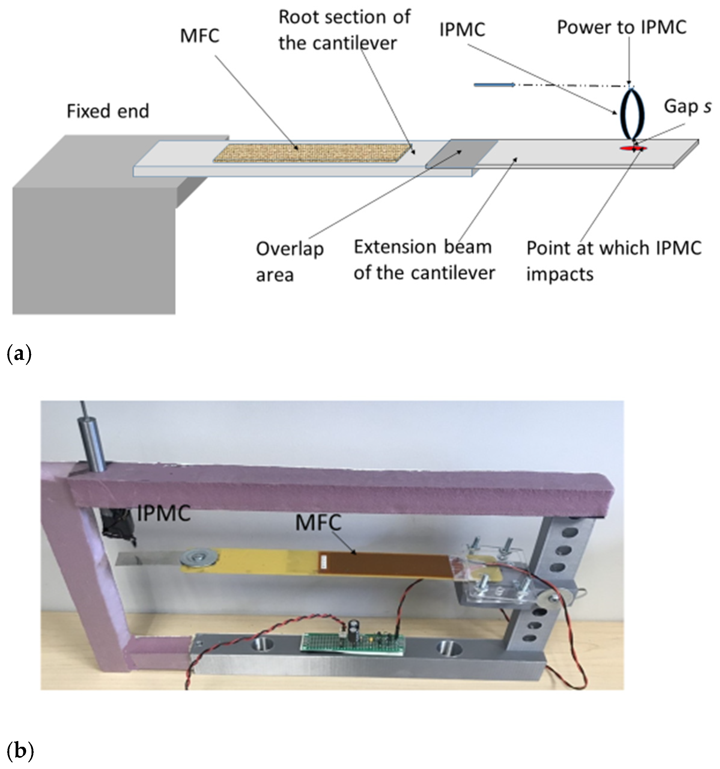
- IPMC, used as a stopper for tuning, consumes only about 25 to 50 µW for activation and much less to keep it in that state if required for a longer period.
- Part of the power generated by the harvester can be used for powering the IPMC stopper, which functions on a 1 to 4 V supply.
- The power generated by the harvester can be used to trickle charge a supercapacitor to store the generated power. This power can then be used to power sensors and data transmission circuits periodically and for short durations as required.
- In the application scenarios presented here, the IPMC was powered manually from power generated by the harvester. The sensor and transmission circuits were powered manually using the generated power from the harvester for the duration required for the transmission of data.
- A supercapacitor circuit was used to store the power generated in application 3. Once the supercapacitor is charged, every measurement brings down the supercapacitor voltage by about 0.2 V. The unit takes about 10 to 15 min of vibrations to make up for the power used. Charging the supercapacitor from 0 to 3 V took about three hours and twenty minutes.
- The same harvester was used for all the application scenarios presented.
- The device is amenable to fabrication in MEMS form. When this is undertaken, it can be integrated with a low-power transmitter, a low-power microcontroller, and low-power sensors as required for autonomous operation.
2. Materials and Methods
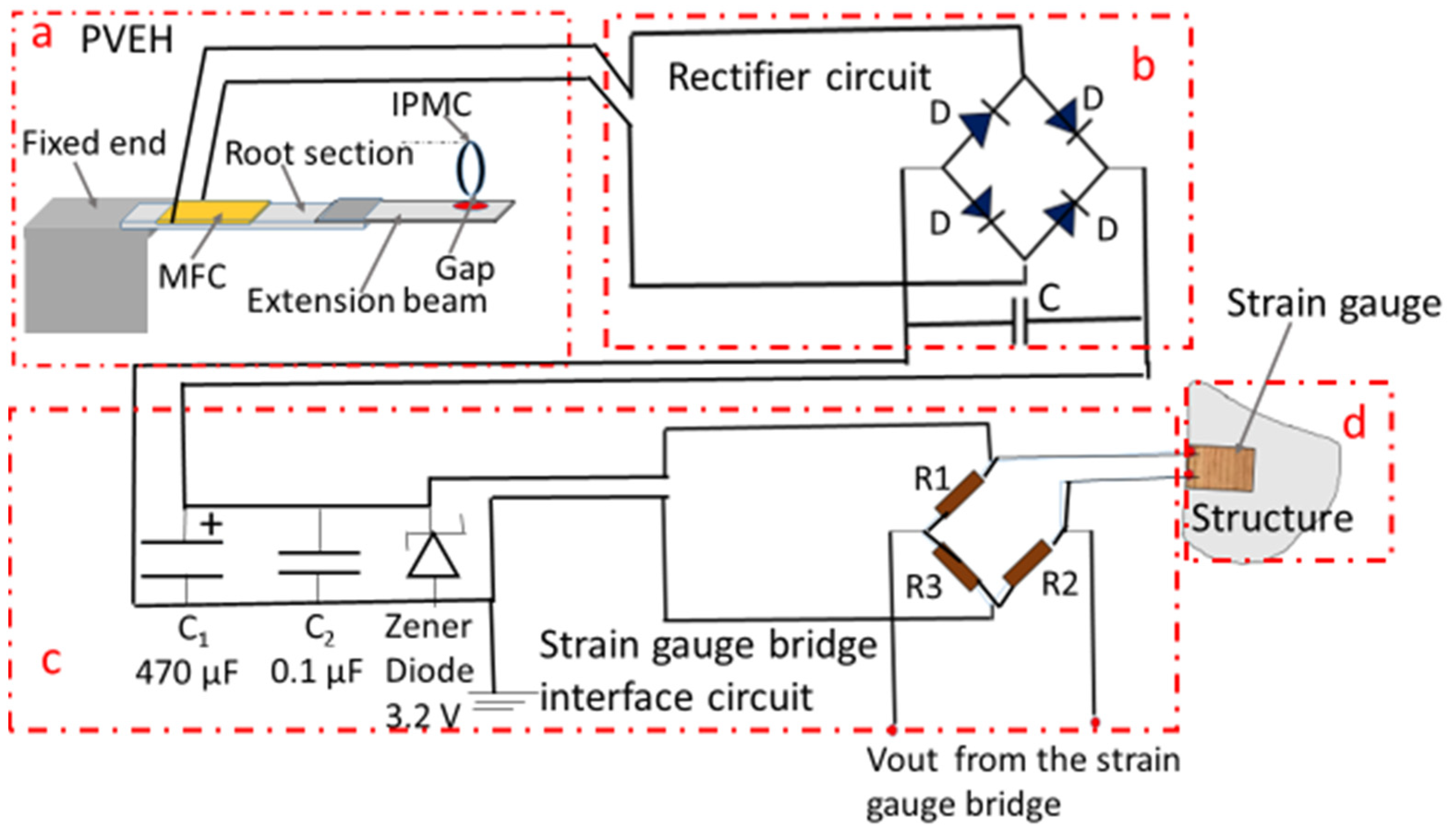
2.1. Application 1
2.2. Application 2
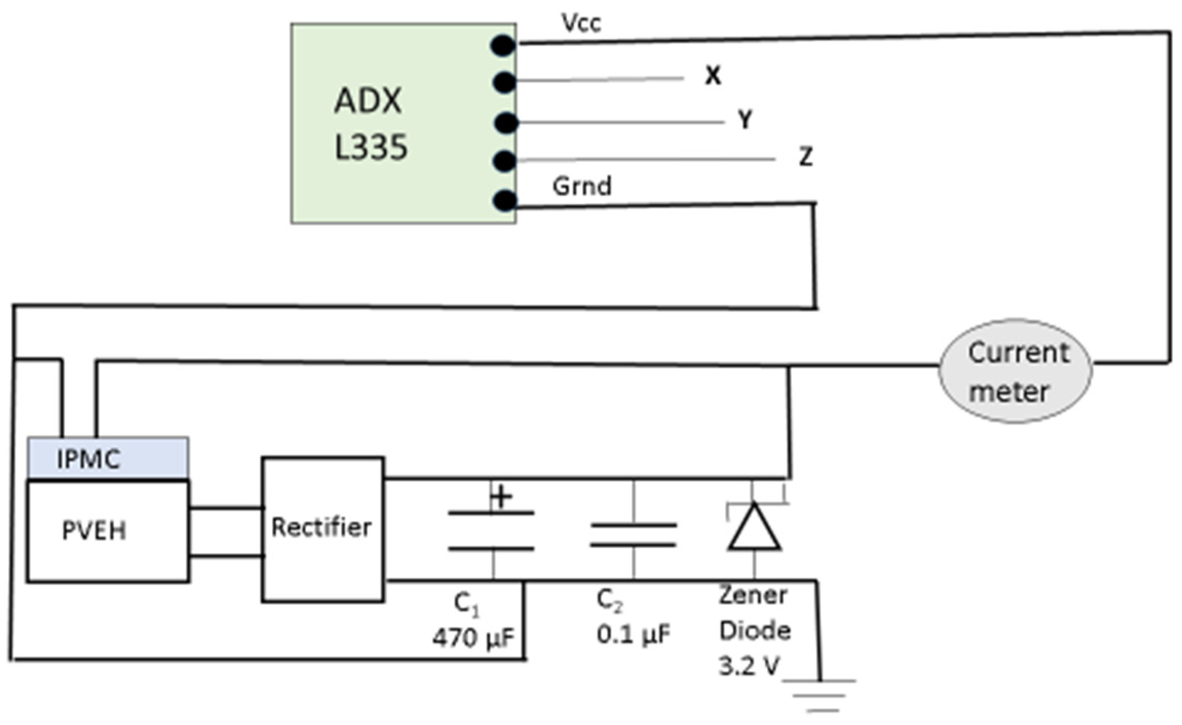
2.3. Application 3
3. Results and Discussion
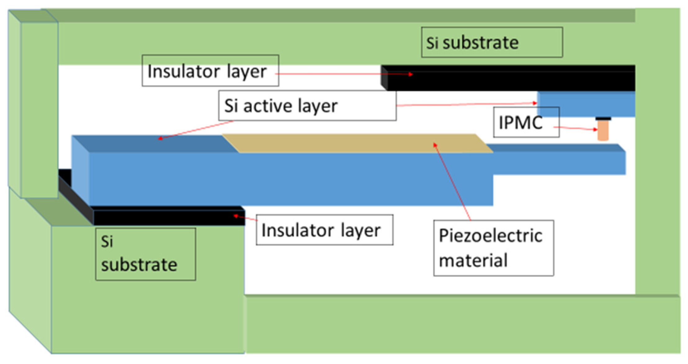
Future Work: Proposed Microelectromechanical System (MEMS) Design of the Tunable Piezoelectric Vibration Energy Harvester (PVEH)
4. Conclusions
- The novel tunable PVEH can continuously provide power to low-power devices such as sensors and transmitters.
- The device generates power at the adjacent frequencies to the basic resonant frequency also, due to the stopper action of IPMC.
- The proposed PVEH, fabricated in MEMS form, can be integrated with other low-power sensors, transmitters, and microcontrollers as required for different applications.
- The MEMS version of the novel device can be easily integrated with sensor arrays.
5. Patents
Author Contributions
Funding
Data Availability Statement
Acknowledgments
Conflicts of Interest
References
- Alla, R.; Bybi, A.; Benhiba, A.; Drissi, H. Overview of piezoelectric energy harvesting technology in the tire condition monitoring systems. E3S Web Conf. 2022, 336, 00022. [Google Scholar] [CrossRef]
- Hosseinkhani, A.; Younesian, D.; Eghbali, P.; Moayedizadeh, A.; Fassih, A. Sound and vibration energy harvesting for railway applications: A review on linear and nonlinear techniques. Energy Rep. 2021, 7, 852–874. [Google Scholar] [CrossRef]
- Esmaeeli, R.; Aliniagerdroudbari, H.; Hashemi, S.R.; Nazari, A.; Alhadri, M.; Zakri, W.; Mohammed, A.H.; Batur, C.; Farhad, S. A rainbow piezoelectric energy harvesting system for intelligent tire monitoring applications. J. Energy Resour. Technol. 2019, 141, 062007. [Google Scholar] [CrossRef]
- Goel, C.; Srinivas, G. Mechanisms and applications of vibration energy harvesting in solid rocket motors. Microsyst. Technol. 2021, 27, 3927–3933. [Google Scholar] [CrossRef]
- Beeby, S.P.; Zhu, D. Vibration energy harvesting: Fabrication, miniaturisation and applications. In Smart Sensors, Actuators, and MEMS VII; and Cyber Physical Systems, Proceedings of the SPIE Microtechnologies Barcelona, Spain, 4–6 May 2015; SPIE: Bellingham, WA, USA, 2015; Volume 9517, p. 951703. [Google Scholar] [CrossRef]
- Khan, F.U.; Ahmad, I. Review of energy harvesters utilizing bridge vibrations. Shock Vib. 2016, 2016, 1340402. [Google Scholar] [CrossRef]
- Ali, F.; Raza, W.; Li, X.; Gul, H.; Kim, K.H. Piezoelectric energy harvesters for biomedical applications. Nano Energy 2019, 57, 879–902. [Google Scholar] [CrossRef]
- Hwang, G.T.; Byun, M.; Jeong, C.K.; Lee, K.J. Flexible piezoelectric thin-film energy harvesters and nanosensors for biomedical applications. Adv. Healthc. Mater. 2015, 4, 646–658. [Google Scholar] [CrossRef]
- Panda, S.; Hajra, S.; Mistewicz, K.; In-na, P.; Sahu, M.; Rajaitha, P.M.; Kim, H.J. Piezoelectric energy harvesting systems for biomedical applications. Nano Energy 2022, 100, 107514. [Google Scholar] [CrossRef]
- Han, M.; Wang, H.; Yang, Y.; Liang, C.; Bai, W.; Yan, Z.; Li, H.; Xue, Y.; Wang, X.; Akar, B.; et al. Three-dimensional piezoelectric polymer microsystems for vibrational energy harvesting, robotic interfaces and biomedical implants. Nat. Electron. 2019, 2, 26–35. [Google Scholar] [CrossRef]
- Mhetre, M.R.; Nagdeo, N.S.; Abhyankar, H.K. Micro energy harvesting for biomedical applications: A review. In Proceedings of the 2011 3rd International Conference on Electronics Computer Technology, Kanyakumari, India, 8–10 April 2011; IEEE: Piscataway, NJ, USA, 2011; Volume 3, pp. 1–5. [Google Scholar]
- Zheng, Q.; Shi, B.; Li, Z.; Wang, Z.L. Recent progress on piezoelectric and triboelectric energy harvesters in biomedical systems. Adv. Sci. 2017, 4, 1700029. [Google Scholar] [CrossRef]
- Townsend, S.; Grigg, S.; Picelli, R.; Featherston, C.; Kim, H.A. Topology optimization of vibrational piezoelectric energy harvesters for structural health monitoring applications. J. Intell. Mater. Syst. Struct. 2019, 30, 2894–2907. [Google Scholar] [CrossRef]
- Maruccio, C.; Quaranta, G.; De Lorenzis, L.; Monti, G. Energy harvesting from electrospun piezoelectric nanofibers for structural health monitoring of a cable-stayed bridge. Smart Mater. Struct. 2016, 25, 085040. [Google Scholar] [CrossRef]
- Saadon, S.; Sidek, O. A review of vibration-based MEMS piezoelectric energy harvesters. Energy Convers. Manag. 2011, 52, 500–504. [Google Scholar] [CrossRef]
- Raghavan, S.; Gupta, R. A novel design and performance results of an electrically tunable piezoelectric vibration energy harvester (TPVEH). J. Compos. Sci. 2020, 4, 39. [Google Scholar] [CrossRef]
- Raghavan, S.; Sharma, A.; Gupta, R. Resonant frequency tuning of a novel piezoelectric vibration energy harvester (PVEH). Mech. Adv. Mater. Struct. 2023, 1–16. [Google Scholar] [CrossRef]
- Self-Tuning Piezoelectric Vibration Energy Harvester. U.S. Patent Application No. 20210159816, 23 November 2020.
- Punning, A.; Anton, M.; Kruusmaa, M.; Aabloo, A. An engineering approach to reduced power consumption of IPMC (Ion-Polymer Metal Composite) actuators. In Proceedings of the 2005 International Conference on Advanced Robotics, ICAR ’05, Proceedings 2005, Seattle, WA, USA, 18–20 July 2005; Volume 2005, pp. 856–863. [Google Scholar] [CrossRef]
- Wang, H.S.; Cho, J.; Song, D.S.; Jang, J.H.; Jho, J.Y.; Park, J.H. High-Performance Electroactive Polymer Actuators Based on Ultrathick Ionic Polymer-Metal Composites with Nanodispersed Metal Electrodes. ACS Appl. Mater. Interfaces 2017, 9, 21998–22005. [Google Scholar] [CrossRef]
- Shahinpoor, M.; Bar-Cohen, Y.; Simpson, J.O.; Smith, J. Ionic polymer-metal composites (IPMCs) as biomimetic sensors, actuators and artificial muscles—A review. Smart Mater. Struct. 1998, 7, R15. [Google Scholar] [CrossRef]
- Kim, B.; Kim, B.M.; Ryu, J.; Oh, I.-H.; Lee, S.-K.; Cha, S.-E.; Pak, J. Analysis of mechanical characteristics of the ionic polymer metal composite (IPMC) actuator using cast ion-exchange film. In Proceedings of the Smart Structures and Materials 2003: Electroactive Polymer Actuators and Devices (EAPAD), San Diego, CA, USA, 2–6 March 2003; Volume 5051, pp. 486–496. [Google Scholar] [CrossRef]
- Tamagawa, H.; Okada, K.; Mulembo, T.; Sasaki, M.; Naito, K.; Nagai, G.; Nitta, T.; Yew, K.-C.; Ikeda, K. Simultaneous enhancement of bending and blocking force of an ionic polymer-metal composite (IPMC) by the active use of its material characteristics change. Actuators 2019, 8, 29. [Google Scholar] [CrossRef]
- Nemat-nasser, S.; Thomas, C.W. CHAPTER 6 Ionomeric Polymer-Metal Composites. In Electroactive Polymers Actuators as Artificial Muscles—Reality, Potential and Challenges; SPIE Optical Engineering Press: Bellingham, WA, USA, 2004; pp. 171–230. [Google Scholar]
- Paquette, J.W.; Kim, K.J.; Nam, J.D.; Tak, Y.S. An equivalent circuit model for ionic polymer-metal composites and their performance improvement by a clay-based polymer nano-composite technique. J. Intell. Mater. Syst. Struct. 2003, 14, 633–642. [Google Scholar] [CrossRef]
- Smart Material Corporation. Smart Material. Available online: https://smart-material.com/ (accessed on 3 January 2022).
- Environmental Robots Inc., Products. Available online: https://www.environmental-robots.com/ (accessed on 2 September 2022).
- Shahinpoor, M. Potential applications of electroactive polymer sensors and actuators in MEMS technologies. In Smart Materials, Proceedings of the Smart Materials and MEMS, 2000, Melbourne, Australia, 13–15 December 2000; International Society for Optics and Photonics: Bellingham, WA, USA, 2001; Volume 4234, pp. 203–214. [Google Scholar]
- Shahinpoor, M.; Kim, K.J. Ionic polymer–metal composites: IV. Industrial and medical applications. Smart Mater. Struct. 2004, 14, 197. [Google Scholar] [CrossRef]
- Chang, X.L.; Chee, P.S.; Lim, E.H. Ionic Polymer Actuator With Crenellated Structures for MEMs Application. In Proceedings of the 2020 IEEE International Conference on Semiconductor Electronics (ICSE), Kuala Lumpur, Malaysia, 28–29 July 2020; IEEE: Piscataway, NJ, USA, 2020; pp. 160–163. [Google Scholar]
- Chung, C.K.; Fung, P.K.; Hong, Y.Z.; Ju, M.S.; Lin CC, K.; Wu, T.C. A novel fabrication of ionic polymer-metal composites (IPMC) actuator with silver nano-powders. Sens. Actuators B Chem. 2006, 117, 367–375. [Google Scholar] [CrossRef]
- Lei, H.; Li, W.; Tan, X. Microfabrication of IPMC cilia for bio-inspired flow sensing. In Electroactive Polymer Actuators and Devices (EAPAD) 2012, Proceedings of the SPIE Smart Structures and Materials + Nondestructive Evaluation and Health Monitoring, San Diego, CA, USA, 11–15 March 2012; SPIE: Bellingham, WA, USA, 2012; Volume 8340, pp. 331–339. [Google Scholar]
- Marzencki, M.; Basrour, S.; Charlot, B.; Spirkovich, S.; Colin, M. A MEMS piezoelectric vibration energy harvesting device. In Proceedings of the PowerMEMS 2005, Tokyo, Japan, 28–30 November 2005; pp. 45–48. [Google Scholar]


Disclaimer/Publisher’s Note: The statements, opinions and data contained in all publications are solely those of the individual author(s) and contributor(s) and not of MDPI and/or the editor(s). MDPI and/or the editor(s) disclaim responsibility for any injury to people or property resulting from any ideas, methods, instructions or products referred to in the content. |
© 2023 by the authors. Licensee MDPI, Basel, Switzerland. This article is an open access article distributed under the terms and conditions of the Creative Commons Attribution (CC BY) license (https://creativecommons.org/licenses/by/4.0/).
Share and Cite
Raghavan, S.; Gupta, R.; Sharma, L. Applications of a Novel Tunable Piezoelectric Vibration Energy Harvester. Micromachines 2023, 14, 1782. https://doi.org/10.3390/mi14091782
Raghavan S, Gupta R, Sharma L. Applications of a Novel Tunable Piezoelectric Vibration Energy Harvester. Micromachines. 2023; 14(9):1782. https://doi.org/10.3390/mi14091782
Chicago/Turabian StyleRaghavan, Sreekumari, Rishi Gupta, and Loveleen Sharma. 2023. "Applications of a Novel Tunable Piezoelectric Vibration Energy Harvester" Micromachines 14, no. 9: 1782. https://doi.org/10.3390/mi14091782
APA StyleRaghavan, S., Gupta, R., & Sharma, L. (2023). Applications of a Novel Tunable Piezoelectric Vibration Energy Harvester. Micromachines, 14(9), 1782. https://doi.org/10.3390/mi14091782