Abstract
This study conducted longitudinal ultrasonic-assisted milling (UAM) tests and optimized a combination of milling technological parameters to achieve high-quality machining of TC18 titanium alloy. The motion paths of the cutter under the coupled superposition states of longitudinal ultrasonic vibration and end milling were analyzed. Based on the orthogonal test, the cutting forces, cutting temperatures, residual stresses, and surface topographical patterns of TC18 specimens under different UAM conditions (cutting speeds, feeds per tooth, cutting depths, and ultrasonic vibration amplitudes) were examined. The differences between ordinary milling and UAM in terms of machining performance were compared. Using UAM, numerous characteristics (including variable cutting thickness in the cutting area, variable cutting front angles of the tool, and the lifting of the cuttings by the tool) were optimized, reducing the average cutting force in all directions, lowering the cutting temperature, increasing the surface residual compressive stress, and significantly improving the surface morphology. Finally, fish scale bionic microtextures with clear, uniform, and regular patterns were formed on the machined surface. High-frequency vibration can improve material removal convenience, thus reducing surface roughness. The introduction of longitudinal ultrasonic vibration to the end milling process can overcome the limitations of traditional processing. The optimal combination of UAM parameters for titanium alloy machining was determined through the end milling orthogonal test with compound ultrasonic vibration, which significantly improved the surface quality of TC18 workpieces. This study provides insightful reference data for subsequent machining process optimization.
1. Introduction
Titanium alloy (TC18) is a typical near-β phase Ti alloy with a nominal composition of Ti-5Al-5Mo-5 V-1Cr-1Fe. Due to an excellent combination of intrinsic qualities, including low thermal conductivity, high specific strength, and high corrosion resistance, Ti alloys show broad application prospects when used as structural components in the aerospace field and light bearings; however, Ti alloys are relatively difficult to process, which remains a bottleneck problem.
Gaining in-depth knowledge of Ti alloy product processing technology and technical parameters is of insightful guidance for engineering applications. Tej Pratap et al. established the cutting force model during the milling process with the Johson–Cook constitutive equation [1,2] and performed related simulations to analyze the stress distribution, temperature rise distribution, and cutting force during the machining process of Ti alloy (Ti6A14V); moreover, they combined tests to validate the established model and cutting force. Wang et al. milled Ti alloy (TA15) after the filling of cutting fluid and investigated the wear condition of the coated cutting tool, the surface topography of the workpiece, and the variation of cutting force during the manufacturing process [2]. According to their results, both the cutting force and the wear of the cutting tool increased slowly and then violently with milling time. The surface roughness of the processed workpiece was negatively correlated with tool wear [2,3].
Ultrasonic-assisted cutting exceeds ordinary cutting methods in Ti alloy machining. Based on the principle of multiple contacts and separations between the cutter tool and the workpiece, scholars established an analysis model of ultrasonic-assisted milling (UAM) [4,5,6]; by comparing the effects of various technological parameters on the cutting force and surface morphology during the Ti alloy machining process using two methods, it was concluded that ultrasonic vibration cutting technology was superior to the traditional technique. Scholars worldwide have employed ultrasonic-assisted cutting methods to examine the surface integrity of difficult-to-process materials [7,8,9,10,11], which can provide a new approach for surface morphology investigations, such as surface roughness, texture, and frictional wear. Verma et al. [12] conducted in-depth studies on the generation mechanism of temperature rise induced by axial ultrasonic vibration; based on the heat source model, they constructed a prediction model of temperature rise during ultrasonic milling considering the ultrasonic softening effect.
Several scholars performed orthogonal tests to determine the appropriate parameters to explore the effects of ultrasonic-assisted and ordinary milling treatments on the machining parameters of difficult-to-process materials [13,14,15]. Ying et al. conducted longitudinal–torsional ultrasonic-assisted milling (UAM) on Ti6A14V and compared the results on cutting force, residual stress, and cutting temperature with the values using traditional milling [16,17,18]; moreover, in combination with orthogonal test and signal–noise factor test results, they investigated the effects of processing parameters on residual stress and finally concluded that LTUV-M can effectively reduce cutting force and cutting temperature and enhance residual pressure stress on the surface.
Some scholars have combined analytical methods and finite element simulations to simulate cutting force and cutting temperature during the machining process of Ti alloys, which can reflect the influence tendency to a certain degree [19,20,21,22]. However, the simulation results can only partially approach the actual machining results. Most studies have focused on popular materials, such as Ti6A14V. Traditional Ti alloys’ machining methods and parameters no longer apply to TC18.
This study focused on TC18 materials and constructed a test platform under longitudinal ultrasonic vibration and end-milling compound conditions. With an orthogonal test, surface milling was performed, and the changes in the milling forces along various directions and the milling temperatures under ultrasonic vibration were measured. Moreover, the residual stresses and the surface morphology on the processed workpiece surfaces were measured. The preset test results provided specific application values for the ultrasonic-assisted processing of TC18.
2. Materials and Methods
2.1. Longitudinal Ultrasonic-Assisted Milling Characteristics
Figure 1 illustrates the motion characteristics of the longitudinal ultrasonic milling tool, where R is the milling tool radius, ns is the tool rotation speed about the principal axis, vw is the tool feed rate along the y-axis, and A and f are the vibration amplitude and frequency of the longitudinal ultrasonic vibration, respectively.
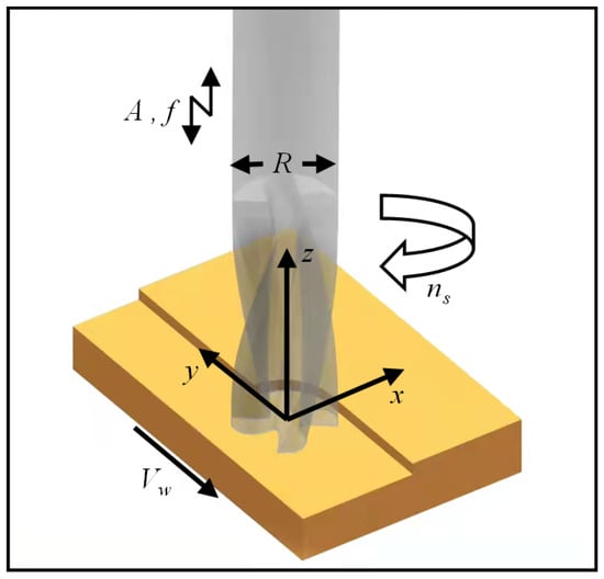
Figure 1.
Illustration of the LUV-EM process.
During the longitudinal ultrasonic-assisted end milling process (LUV-EM), the milling tool can generate high-frequency periodic displacements along the axial direction. Combining conventional milling and longitudinal ultrasonic vibration can improve cutting force, residual stress, surface topography, and milling-induced temperature rise [23,24,25,26].
The motion path equation of the cutting edge in the LUV-EM system can be written as:
Figure 2 compares the motion paths of the milling tool using UAM and ordinary milling (OM). After adding longitudinal ultrasonic vibration, a sinusoidal waveform began to appear in the motion path of the cutting edge.
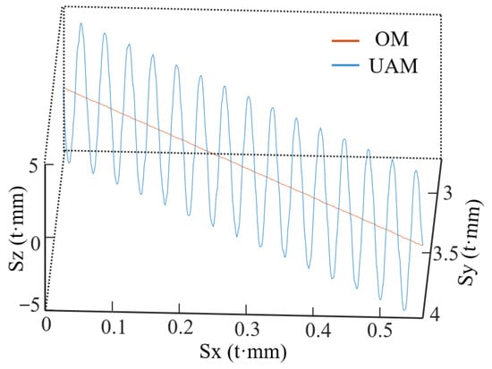
Figure 2.
Comparison of motion paths using OM and UAM.
2.2. Test Device
Ultrasonic milling of TC18 was performed in a CNC machining center (Henfux-HFM 700 L). As shown in Figure 3, the test device mainly consists of a wireless transmission system, ultrasonic tool holder, force measuring system, and temperature measuring system. During the operating process, the electric energy of the ultrasonic power supply is transmitted to the transducer via the wireless transmission system. The amplitude output from the transducer is then magnified by the amplitude transformer and transmitted to the cutter tool to mill materials. The force measuring system (Swiss Kistler Instruments Co., Ltd., Winterthur, Swiss) mainly comprises the milling force-acquisition system (Type 9119AA2), the signal amplifier (Type 5080A), and the display, while an IR imaging sensor (Type IRI-100C2, Xiamen Red Phase Electric Power Equipment Co., Ltd., Xiamen, China) was used to measure temperature.
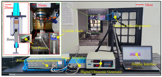
Figure 3.
Illustration of the test device.
2.3. Test Specimen and Tool Parameters
The TC18 test specimens were 15 mm × 6 mm × 8 mm in size. TC18 is an Al alloy consisting of α and β phases. Table 1 lists the chemical composition of the TC18 Ti alloy.

Table 1.
Chemical composition of TC18 alloy (mass fraction).
TC18 mechanical properties were as follows: tensile and yield strengths of 1220 and 1162 MPa, respectively; elongation of 17.4%; and cross-sectional reduction of 48.4%.
During the ultrasonic-assisted milling process, a cutter tool with favorable heat-conducting properties, swarf discharge performance, and a smooth coating was selected to prolong service life. Moreover, the coating needed to be composed of low-activity materials. This study used a 4-blade integral vertical milling cutter with hard-alloy columns (TM-4R-D8.0R1.0). The milling cutter was 8 mm in diameter. The blade and tool lengths were 20 and 60 mm, respectively. The cutter tool was coated with AlCrXN.
2.4. Test Design
To examine the effects of ultrasonic-assisted milling parameters, this study selected four parameters—the cutting speed vw, the feed fz, the cutting depth ap, and the ultrasonic vibration amplitude A, denoted as A, B, C, and D, respectively. We designed an orthogonal test to measure the cutting forces along three directions (Fx, Fy, and Fz), the surface roughness after precision hard cutting (Ra), the residual stress (Rs), and the cutting temperature (T). We also calculated the results of variance and range. Table 2 lists the present test schemes and results.
Table 2.
Orthogonal test results.
After milling, the residual stress on the surface was measured with an X-ray diffractometer (PROTO-LXRD), while the surface micromorphology was observed under a COXEM EM-30 scanning electron microscope and a white light interferometer.
3. Results
This section may be divided by subheadings. It should provide a concise and precise description of the experimental results and their interpretation, as well as the experimental conclusions that can be drawn.
3.1. Cutting Force
Figure 4 compares the measured cutting forces (Fz) with force sensors under two milling conditions (OM and UAM). Using ultrasonic-assisted milling, the cutting force can be markedly reduced. The results in the 7th group (vw = 25 m/min, fz = 20 μm/r, ap = 0.4 mm, and A = 1.5 μm) and the 10th group (vw = 35 m/min, fz = 12 μm/r, ap = 0.4 mm, and A = 0 μm) of tests were selected for in-depth analysis, as shown in Figure 4a. Generally, Fz can increase with increasing milling speed and feed per tooth. After the addition of ultrasonic-assisted vibration, the cutter tooth can retain contact and separation characteristics during the rotation process, which can change the total contact time between the cutter tool and the specimen to be processed, thereby playing the role of peak clipping for the cutting force, i.e., the peak of the milling force (Fz) can be reduced. Next, the results in the 7th group (vw = 35 m/min, fz = 28 μm/r, ap = 0.2 mm, and A = 2.5 μm) and the 10th group (vw = 35 m/min, fz = 12 μm/r, ap = 0.4 mm, and A = 0 μm) of tests were selected for further comparison. Adding the ultrasonic vibration amplitude can still reduce the milling force Fz. It can be observed from Figure 4a,b that ultrasonic-assisted milling can reduce the peak milling force Fz by 36.4% and 35.8%, respectively. Using longitudinal ultrasonic-assisted vibration, the acquired milling force signal can be converted into a pulse signal so that the collected force signal shows the oscillation characteristics featured by a sinusoidal wave, as shown in Figure 4c,d. It can be observed from Figure 4c that before the addition of ultrasonic-assisted milling, no force was applied to the specimen after the signal tooth, and the horizontal rotational inertia was greatest when the cutter tool contacted the TC18 alloy, accompanied by the generation of resonance. Accordingly, the collected milling force shows a large amplitude and sharp peaks. After adding longitudinal ultrasonic vibration, the cutter tool took sinusoidal motion in the vertical direction, which can offset the negative impact induced by horizontal rotational inertia. The peak of the milling force signal became smoother. The sinusoidal profile became more evident with increasing vibration amplitude, as shown in Figure 4d.
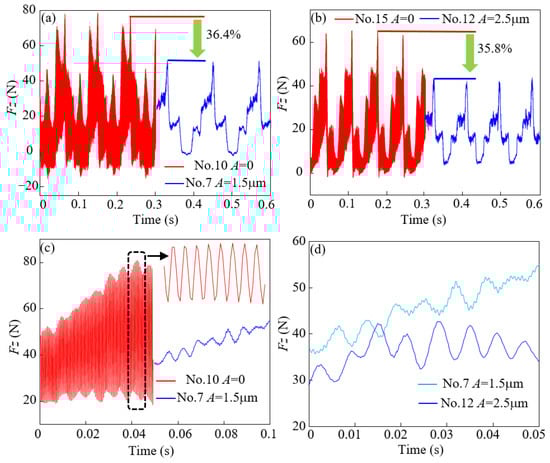
Figure 4.
Milling force signal acquisition diagram. (a) shows the comparison of milling force for amplitude A = 1.5 μm and A = 0. (b) shows the comparison of milling force for amplitude A = 2.5 μm and A = 0. (c) compares the sine waveform for amplitude A = 1.5 μm and A = 0. (d) compares the sine waveform for amplitude A = 1.5 μm and A = 2.5 μm.
Table 3 lists the variance analysis results of the cutting forces along different directions. It can be observed that the feed per tooth imposed significant effects on Fx and Fy, while the cutting depth can significantly affect Fx.
Table 3.
Significance analysis of the milling force.
Figure 5 displays the effects of various cutting parameters on the cutting forces along different directions (Fx, Fy, and Fz). As the milling speed increased, Fx and Fy dropped slightly, and Fz increased slightly, as shown in Figure 5a,e,i. As the feed and cutting depth increased, the cutting forces Fx, Fy, and Fz increased significantly (as shown in Figure 5b,c,f,g,j,k. As the vibration amplitude increased, Fx and Fy first dropped slightly. As the vibration amplitude increased to 3.5 mm, the vibration displacement increased during the feeding process of the cutter tool, and the total contact time between the cutter tool and the specimen was prolonged, increasing Fx and Fy, as shown in Figure 5d,h. Due to the longitudinal ultrasonic vibration of the cutter tool [27], Fz dropped significantly. As the amplitude increased, the displacement between the cutter tool and the specimen increased, accompanied by increased generated longitudinal contact force. Accordingly, Fz increased to a certain degree. However, due to the effect of system stability, a further increase in the amplitude may gradually reduce the cutting force Fz. Through comprehensive evaluation, adding ultrasonic vibration can reduce cutting force by 15% on average.

Figure 5.
Effects of various milling parameters on the milling force. (a–d) show the trends of milling speed, feed per tooth, milling depth, and ultrasonic amplitude on milling force Fx, (e–h) show the trends of milling speed, feed per tooth, milling depth, and ultrasonic amplitude on milling force Fy, and (i–l) show the trends of milling speed, feed per tooth, milling depth, and ultrasonic amplitude on milling force Fz, respectively.
3.2. Milling Temperature
Figure 6 compares the milling temperature variations using OM and UAM. As shown in Figure 6a,b, after the addition of ultrasonic vibration, the cutting force was lowered, and the heat dissipation time for the separation of chippings during the vibration of the cutter tool and specimen was prolonged. Accordingly, in contrast with the OM results, the instantaneous friction coefficient dropped, and the milling temperature was significantly reduced, by approximately 42%. With increasing ultrasonic vibration amplitude, the mean temperature increased. At an ultrasonic vibration amplitude of 3.5 μm, the surface temperature of the specimen can be effectively improved [28].
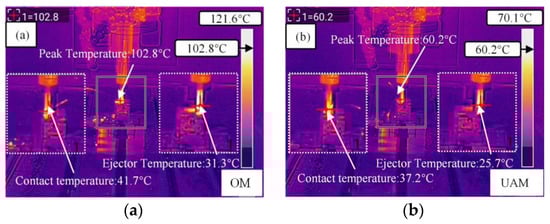
Figure 6.
Comparison of the variation in peak milling temperature using OM and UAM. (a) shows the temperature variation using OM, including the incoming temperature, the working temperature, and the receding tool temperature. (b) shows the temperature variation using UAM, including incoming temperature, working temperature, and retired tool temperature.
Figure 7 illustrates the effects of various milling parameters on the mean surface temperature of the specimen. As the feed increased, the contact displacement between the tooth per edge and the specimen increased, and the mean frictional coefficient increased, increasing the mean milling temperature. With increasing milling depth, the cutting force increased, causing a rapid increase in the milling temperature. In contrast, the milling speed slightly affected the mean temperature.
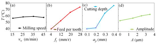
Figure 7.
Influencing tendencies of various milling parameters on mean temperature. (a) shows the effect of milling speed on temperature, (b) shows the effect of feed per tooth on temperature, (c) shows the effect of milling depth on temperature, and (d) shows the effect of ultrasonic amplitude on temperature.
3.3. Residual Stress
Residual stress may persist on the specimen surface after the ultrasonic-assisted milling process of TC18. According to the experimental results in Table 2, ultrasonic-assisted milling can enhance this residual stress on the surface. Table 4 and Table 5 list the variance and range analysis results of various technological parameters, from which it can be easily observed that the amplitude of ultrasonic vibration imposed the most significant effect on the residual compressive stress, followed by the milling speed.
Table 4.
Significance analysis results of the residual stress.
Table 5.
Range analysis results of the residual stress.
Figure 8 displays the effects of various milling parameters on the residual compressive stress using ultrasonic-assisted milling. Since TC18 is a hard, difficult-to-process alloy, the residual compressive stress was high at low cutting speeds; as the cutting speed increased, the residual compressive stress dropped. With increasing ultrasonic vibration amplitude, the residual compressive stress on the surface of the Ti alloy specimen increased rapidly, with a mean extreme of up to 430 MPa. This can be attributed to the impact of ultrasonic vibration on the specimen during the milling process. Accordingly, after adding ultrasonic vibration, the residual stress on the specimen was markedly enhanced compared with the value using ordinary milling.
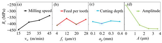
Figure 8.
Influencing tendencies of various milling parameters on residual stress. (a) shows the effect of milling speed on residual stresses, (b) shows the effect of feed per tooth on residual stresses, (c) shows the effect of milling depth on residual stresses, and (d) shows the effect of ultrasonic amplitude on residual stresses.
3.4. Surface Roughness
Figure 9 shows the variations in the surface roughness with the cutting speed vw, the feed fz, the cutting depth ap and the amplitude of ultrasonic vibration A. As the cutting speed and the cutting depth increased, the surface roughness of the specimen dropped; as the feed increased, the mean roughness first increased by up to 30%; as the vibration of ultrasonic vibration increased, the surface roughness improved and reached an optimal value at an amplitude of 3.5 μm. Under optimal ultrasonic-assisted milling conditions, the surface roughness can be reduced by 44% compared with the value under ordinary milling conditions.
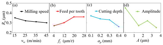
Figure 9.
Influencing tendencies of various milling parameters on surface roughness. (a) shows the effect of milling speed on roughness, (b) shows the effect of feed per tooth on roughness, (c) shows the effect of milling depth on roughness, and (d) shows the effect of ultrasonic amplitude on roughness.
3.5. Surface Morphology
Using a COXEM desk-type scanning electron microscope and white light interferometer, the surface morphological patterns of the specimens were observed at a magnification of 1000, as shown in Figure 10.
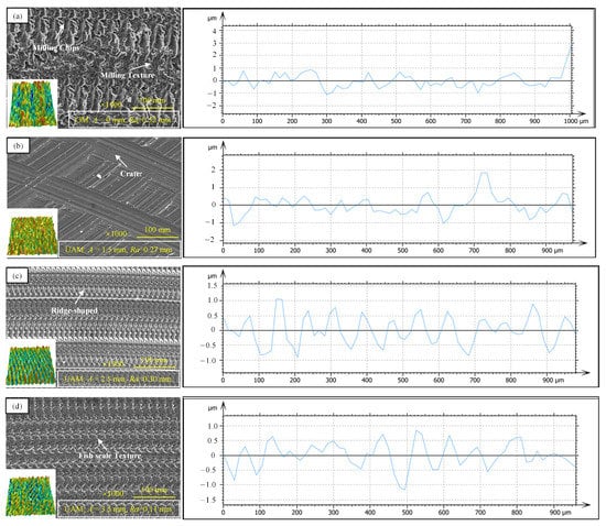
Figure 10.
Surface topographical patterns and roughness degrees of the specimens after different milling processes. (a) shows the surface profile and surface roughness of conventional milling, (b) shows the surface profile and surface roughness of amplitude A = 1.5 μm, (c) shows the surface profile and surface roughness of amplitude A = 2.5 μm, and (d) shows the surface profile and surface roughness of amplitude A = 3.5 μm.
Figure 10a shows the surface morphology of the TC18 specimen using ordinary milling (at zero amplitude of ultrasonic vibration). Banded wavy textures can be observed along the feeding direction of the cutter tool. Figure 10b shows the surface morphology of the TC18 specimen after ultrasonic-assisted milling at an amplitude of 1.5 μm. The surface roughness can be reduced, and the microtextures on the surface show a regular distribution along the feeding direction. Groove structures can be observed at the cutting position of the cutter tool. The existence of microtexture can contribute to the storage of lubricating medium so that lubricating medium can create an interception effect between friction pairs, thereby improving the friction performance of friction pairs. Figure 10c shows the surface morphology of the TC18 specimen after ultrasonic-assisted milling at an amplitude of 2.5 μm, from which a ridged sinusoidal distribution of tight textures along the feeding direction can be observed. As the vibration amplitude increased, the total roughness increased, but the peak roughness dropped. The existence of ridged textures in the friction pairs of Ti alloy bearings can generate adhesive friction, forming anisotropy of the friction force. As the amplitude of ultrasonic vibration increased to 3.5 μm, the surface morphology of the TC18 specimen after ultrasonic-assisted milling was observed, as shown in Figure 10d. Regularly distributed fish scale textures can be observed. Slight roughness and regular surface textures can improve both the friction force and consumption to a certain degree.
3.6. Optimized Combination of Technological Parameters
During the ultrasonic-assisted milling process of the TC18 alloy, the combinations of milling parameters were concluded to achieve good processing performance, as listed in Table 6. Aiming at obtaining intact surface textures and low surface roughness, the A4B1C4D4 combination of technological parameters (at a milling speed of 45 m/min, a feed of 4 μm/r, a cutting depth of 0.4 mm and an ultrasonic vibration amplitude of 0.35 μm) can be selected. For the enhancement of residual compressive stress on the surface, the A1B1C2D4 combination can be selected. To reduce the milling temperature, the A1B1C1D4 combination can be selected.
Table 6.
Optimization combinations of technological parameters.
4. Conclusions
The results obtained made it possible to draw the following conclusions:
- (1)
- By comparing the machining effects under ordinary milling and longitudinal ultrasonic-assisted milling, it can be found that the mean cutting force can be reduced by 15% due to high-speed contact and separation between the longitudinal ultrasonic vibration cutter tool and the workpiece, thereby effectively enhancing the cutting performance.
- (2)
- During the longitudinal ultrasonic vibration milling process, prolonging the separation time between the cutter tool and the workpiece can increase the heat dissipation time, remarkably improving the temperature rise during the milling process. The peak temperature can be reduced by up to 42%.
- (3)
- Adding longitudinal ultrasonic vibration to the milling process can enhance the residual compressive stress on the specimen surface. The improvement became more evident with increasing amplitude. The peak residual compressive stress can be enhanced by approximately 40%.
- (4)
- Ultrasonic-assisted milling can remarkably improve the surface roughness of TC18 alloys. The maximum reduction of the surface roughness can reach 44% at an ultrasonic vibration amplitude of 3.5 μm.
- (5)
- Prospects for future work: after orthogonal test analysis, some processing parameters on TC18 were accumulated. The subsequent experiments can be expanded based on the excellent processing parameters. Single-factor tests were conducted to investigate the in-depth effects of each parameter on TC18 milling, the effect of machining parameters on force, and thus the difference in surface integrity. Enrichment of the orthogonal test data to obtain the interactive effects of each parameter on force and surface integrity should be considered.
Author Contributions
Conceptualization, G.L. and W.X.; methodology, G.L. and L.Y.; validation, G.L., W.X. and L.Y.; data curation, H.W., Y.C. and W.X.; writing—original draft preparation, G.L. and H.W.; writing—review and editing, G.L. and S.Z.; supervision, G.L. and S.Z.; project administration, G.L.; funding acquisition, L.Y. All authors have read and agreed to the published version of the manuscript.
Funding
This research was funded by Key R & D and Promotion Special/Tackling Key Problems in Science and Technology in Henan province, China (grant No. 212102210349); Mechanical Manufacturing and its Automation Key Disciplines of Pingdingshan University (grant No. PXY-JXZDXK-202306).
Data Availability Statement
All relevant data can be obtained in this article.
Conflicts of Interest
The authors declare no conflict of interest.
References
- Lei, P.; Wu, H.B. Effect of ultrasonic vibration on ultra-precision diamond turning of Ti6Al4V. Int. J. Adv. Manuf. Technol. 2019, 103, 433–440. [Google Scholar] [CrossRef]
- Wang, M.H.; Zhou, D.L.; Zheng, Y.H. Experiment and analysis of milling titanium alloy TA15. Tool Eng. 2018, 52, 109–112. [Google Scholar]
- Ni, C.B.; Zhu, L.; Liu, C.F.; Yang, Z.C. Analytical modeling of tool-workpiece contact rate and experimental study in ultrasonic vibration-assisted milling of Ti-6Al-4 V. Int. J. Mech. Sci. 2018, 142, 97–111. [Google Scholar] [CrossRef]
- Llanos, I.; Campa, A.; Iturbe, A.; Arrazola, P.B. Experimental analysis of cutting force reduction during ultrasonic assisted turning of Ti6Al4V. Procedia CIRP 2018, 77, 81–86. [Google Scholar] [CrossRef]
- Zhang, M.L.; Zhang, D.Y.; Geng, D.X. Effects of tool vibration on surface integrity in rotary ultrasonic elliptical end milling of Ti6-Al-4V. J. Alloys Compound. 2020, 821, 153266. [Google Scholar] [CrossRef]
- Liu, Y.M.; Zheng, Y.P.; Li, J. Study on surface morphology of vibration assisted cutting. Procedia CIRP 2018, 71, 65–70. [Google Scholar] [CrossRef]
- Tao, G.C.; Zhang, J.H.; Shen, X.H. Feasibility study on ultrasonic vibration assisted milling for squamous surface. Procedia CIRP 2016, 42, 847–852. [Google Scholar] [CrossRef]
- Bai, Y.; Yang, M. The influence of superimposed ultrasonic vibration on surface asperities deformation. J. Mat. Proc. Technol. 2016, 229, 367–374. [Google Scholar] [CrossRef]
- Ma, C.; Zhang, J.H.; Tao, G.C. Wear and friction properties of titanium alloy surface subject to ultrasonic vibration assisted milling. Surf. Technol. 2017, 46, 115–119. [Google Scholar]
- Zhang, X.F.; Zheng, K.; Liao, W.H. Investigation on surface integrity for ultrasonic vibration assisted milling titanium alloy. Tool Eng. 2017, 51, 12–16. [Google Scholar]
- Ni, C.B.; Zhu, L.D.; Nino, J.S. Research on the characteristics of cutting force signal and chip in ultrasonic vibration-assisted milling of titanium alloys. J. Mech. Eng. 2019, 55, 207–216. [Google Scholar] [CrossRef]
- Girish, C.V.; Pulak, M.P.; Uday, S.D. Estimation of workpiece-temperature during ultrasonic-vibration assisted milling considering acoustic softening. Int. J. Mech. Sci. 2018, 140, 547–556. [Google Scholar] [CrossRef]
- Girish, C.V.; Pulak, M.P. Machining forces in ultrasonic-vibration assisted end milling. Ultrasonics 2019, 94, 350–363. [Google Scholar]
- Wang, X.M.; Han, J. Study on surface roughness of high speed milling of TC4 titanium alloy. Mech. Design Manuf. 2019, 5, 232–236. [Google Scholar] [CrossRef]
- Ji, S.H.; Ge, M.J.; Lin, Y.P. Experiment and analysis of titanium alloy milling based on orthogonal experimental design. Tool Eng. 2018, 52, 96–100. [Google Scholar]
- Niu, Y.; Jiao, F.; Zhao, B. Experiment of machining induced residual stress in longitudinal torsional ultrasonic assisted milling of Ti-6Al-4 V. Surf. Technol. 2019, 48, 41–51. [Google Scholar]
- Zhao, B.; Li, P.T.; Zhao, C.G. Fractal characterization of surface microtexture of Ti6Al4V subjected to ultrasonic vibration assisted milling. Ultrasonics 2020, 102, 106052. [Google Scholar] [CrossRef]
- Zhu, L.; Ni, C.B.; Yang, Z.C. Investigations of micro-textured surface generation mechanism and tribological properties in ultrasonic vibration-assisted milling of Ti-6Al-4V. Precis. Eng. 2019, 57, 229–243. [Google Scholar] [CrossRef]
- Tej, P.; Karali, P.; Dyakonov, A.A. Modeling cutting force in micro-milling of ti-6al-4v titanium alloy. Proc. Eng. 2015, 129, 134–139. [Google Scholar]
- Wang, B.H.; Cheng, L.; Ding, J.L. Numerical simulation on laser shock peening of TC4 titanium alloy. J. Aerosp. Power 2021, 36, 959–968. [Google Scholar]
- Tan, L.; Zhang, D.H.; Yao, C.F. Effect of high-speed milling parameters on the surface metamorphic layer of TC17 titanium alloy. J. Aeronaut Mat. 2017, 37, 75–81. [Google Scholar]
- Li, S.; Han, J.; Yu, H.; Wang, J.; Lu, M.; Tian, Y.; Lin, J. Finite Element Investigation on Cutting Force and Residual Stress in 3D Elliptical Vibration Cutting Ti6Al4V. Micromachines 2022, 13, 1278. [Google Scholar] [CrossRef] [PubMed]
- Wu, H.B.; Liu, G.; Ke, Y.L. Numerical simulation on surface residual stress for titanium alloy. J. Zhejiang Univ. (Eng. Sci.) 2007, 8, 1389–1393. [Google Scholar]
- He, Z.; Li, G.H.; Sun, Y. Development of experimental study on high-speed cutting of titanium alloys. Tool Eng. 2021, 55, 11–23. [Google Scholar]
- Chen, J.L.; Li, J.F.; Sun, J. Surface residual stress of titanium alloy induced by milling. J. Mech. Strength. 2010, 32, 53–57. [Google Scholar]
- Liu, J.; Fan, B.P.; Chen, Y. FEM simulation of temperature field in ultrasonic vibration grinding of CFRP. Mech. Sci. Technol. Aerosp. Eng. 2020, 39, 821–828. [Google Scholar]
- Xie, W.; Wang, X.; Liu, E.; Wang, J. Research on cutting force and surface integrity of TC18 titanium alloy by longitudinal ultrasonic vibration assisted milling. Int. J. Adv. Manuf. Technol. 2022, 119, 4745–4755. [Google Scholar] [CrossRef]
- Zhao, M.; Zhu, J.; Song, S.; Xue, B.; Zhao, B. Influence of machining parameters in longitudinal-torsional ultrasonic vibration milling titanium alloy for milling force. Int. J. Adv. Manuf. Technol. 2022, 123, 3578–3597. [Google Scholar] [CrossRef]
Disclaimer/Publisher’s Note: The statements, opinions and data contained in all publications are solely those of the individual author(s) and contributor(s) and not of MDPI and/or the editor(s). MDPI and/or the editor(s) disclaim responsibility for any injury to people or property resulting from any ideas, methods, instructions or products referred to in the content. |
© 2023 by the authors. Licensee MDPI, Basel, Switzerland. This article is an open access article distributed under the terms and conditions of the Creative Commons Attribution (CC BY) license (https://creativecommons.org/licenses/by/4.0/).