
Effect of Reticulate Unit Spacing on Microstructure and Properties of Biomimetic 7075 Aluminum Alloy by Laser Cladding
Abstract
:1. Introduction
2. Experimental Materials and Methods
2.1. Materials
2.2. Methods
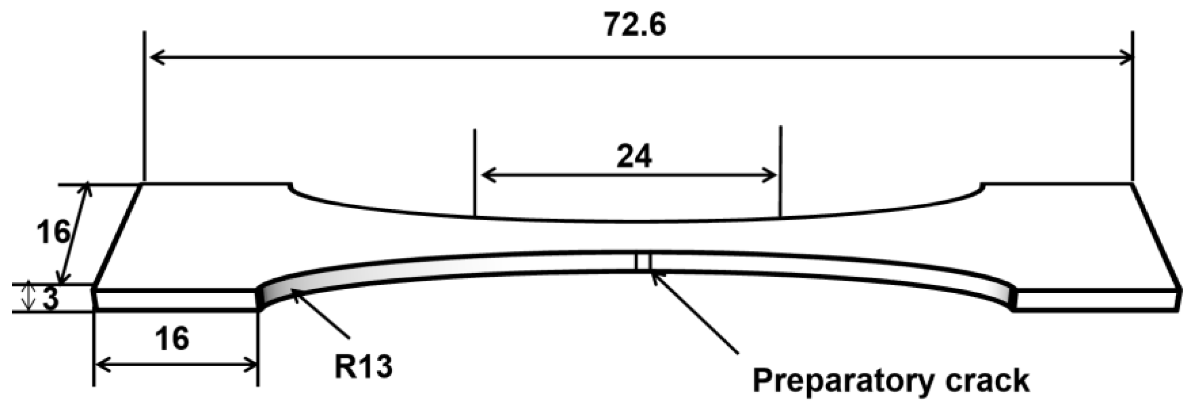
2.2.1. Sample Preparation
2.2.2. Performance Characterization
3. Results and Discussion
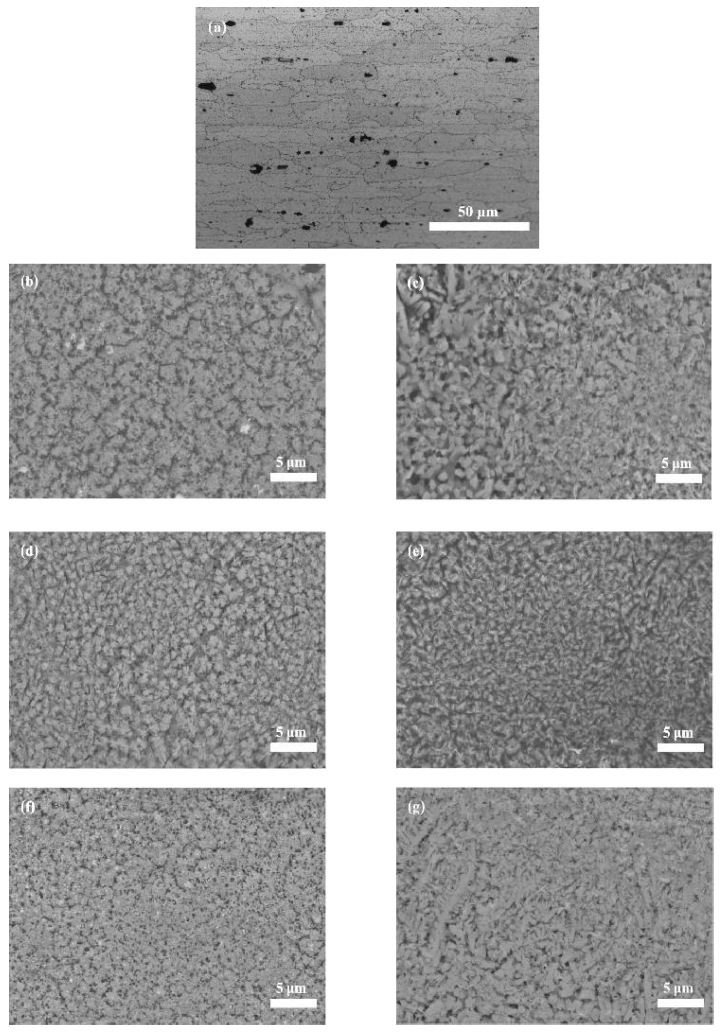
3.1. Microstructures
3.2. Microhardness
3.3. Tensile Results of Biomimetic Samples with Different Spacings
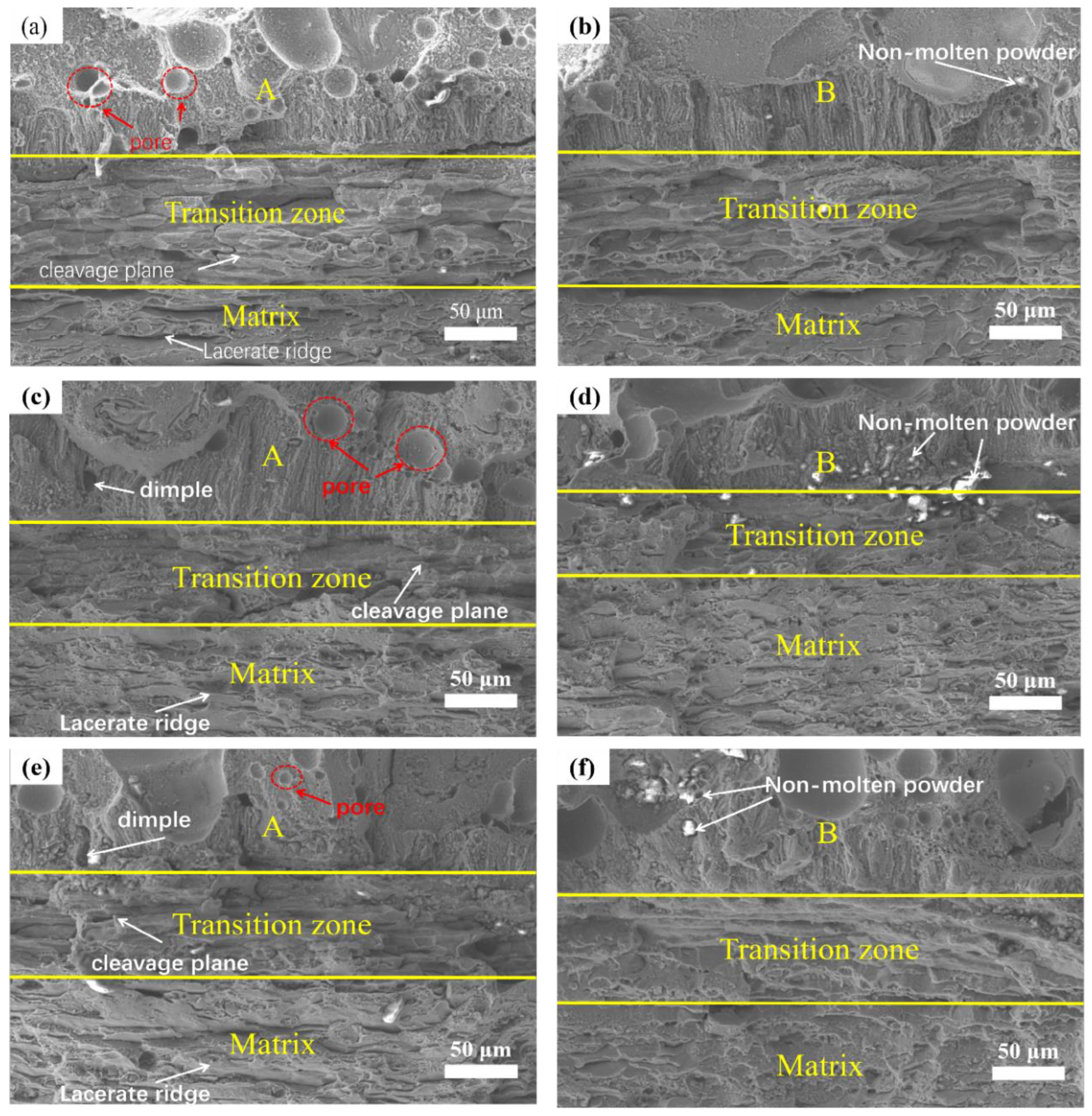
3.4. Fracture Surface
3.5. Mechanism
4. Conclusions
- (1)
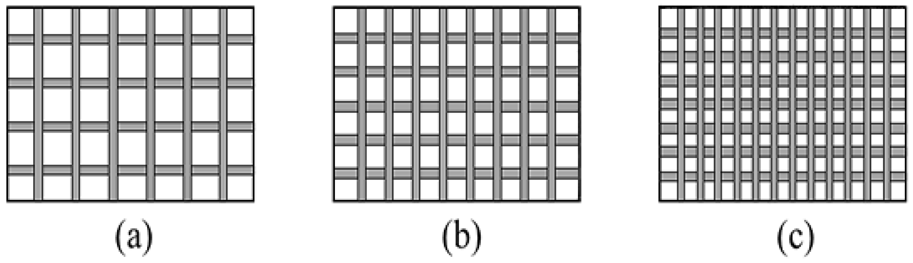
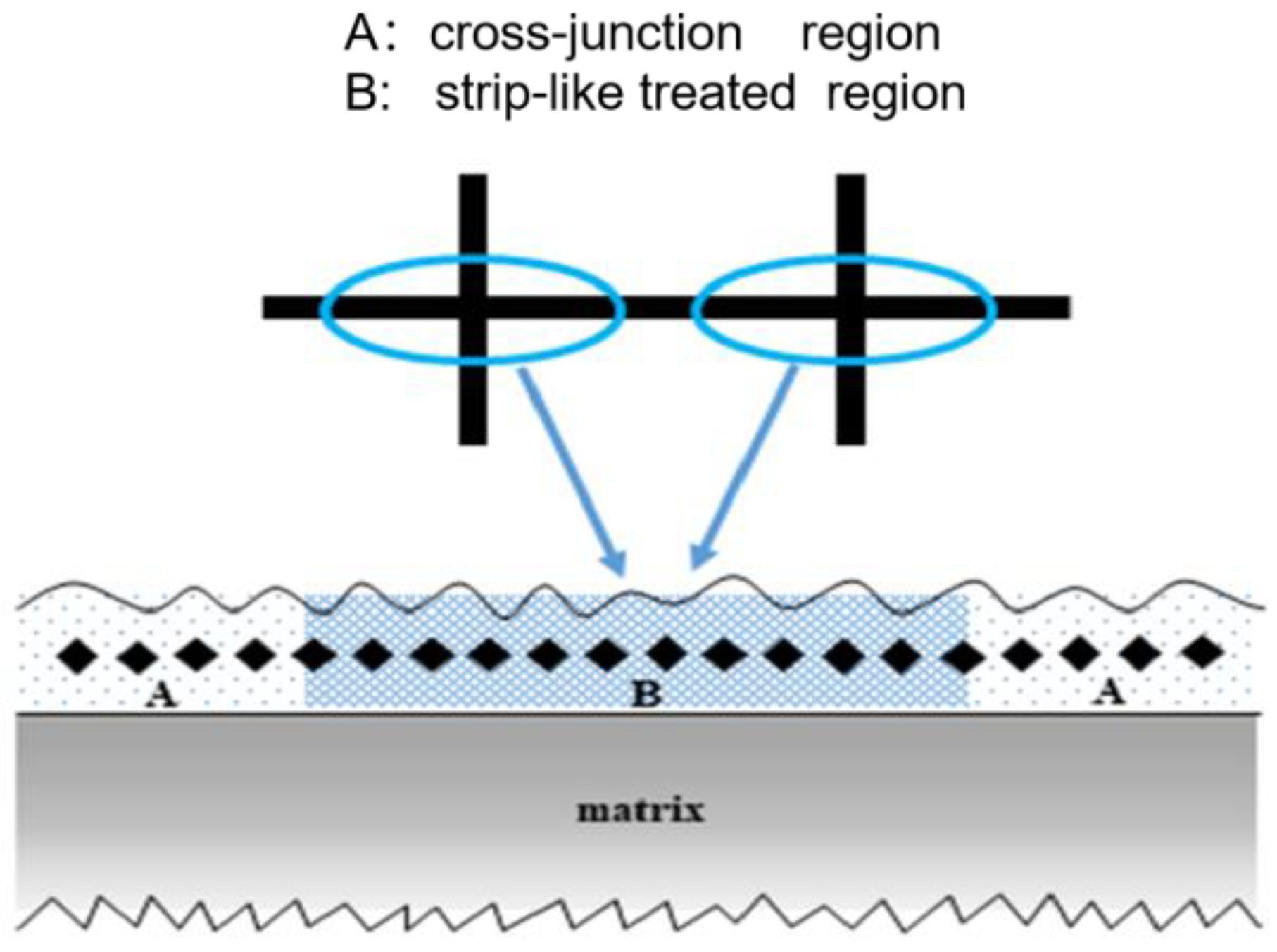
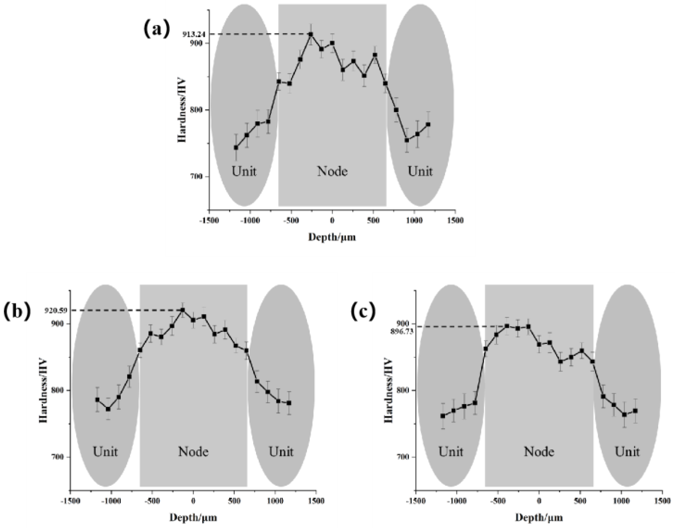
- Compared with the unprocessed region of biomimetic samples, the microstructure of the processed regions (units) with various spacings were finer, and the microhardness was improved. Moreover, spacings of reticulate unit affected the microstructure and microhardness. Among the microstructure of the processed regions (units) with various spacings, compared to 1.5 mm and 3.5 mm, 2.5 mm had the finest crystal and the highest microhardness, no matter the strip-like region or the cross-junction region.
- (2)
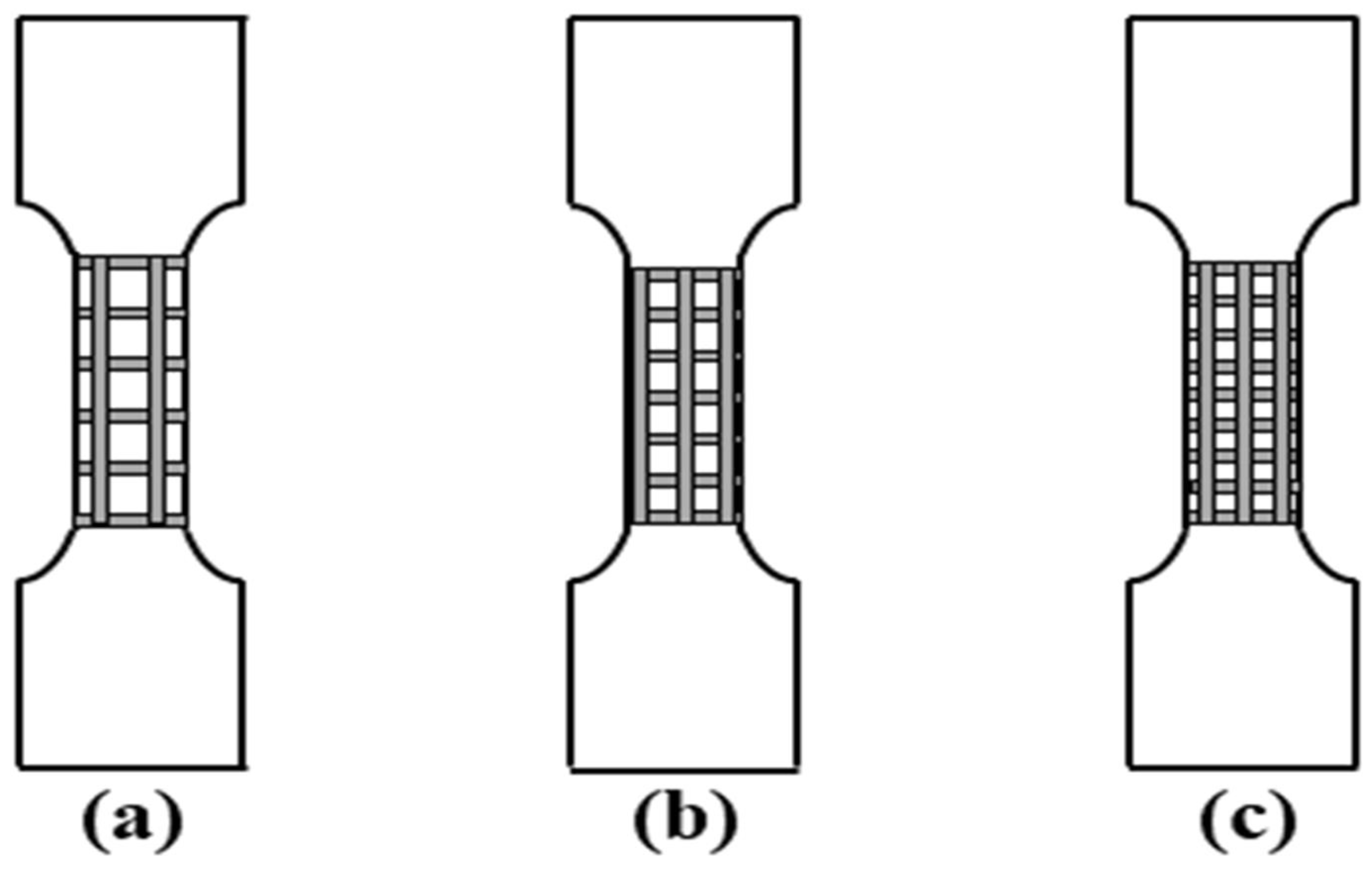
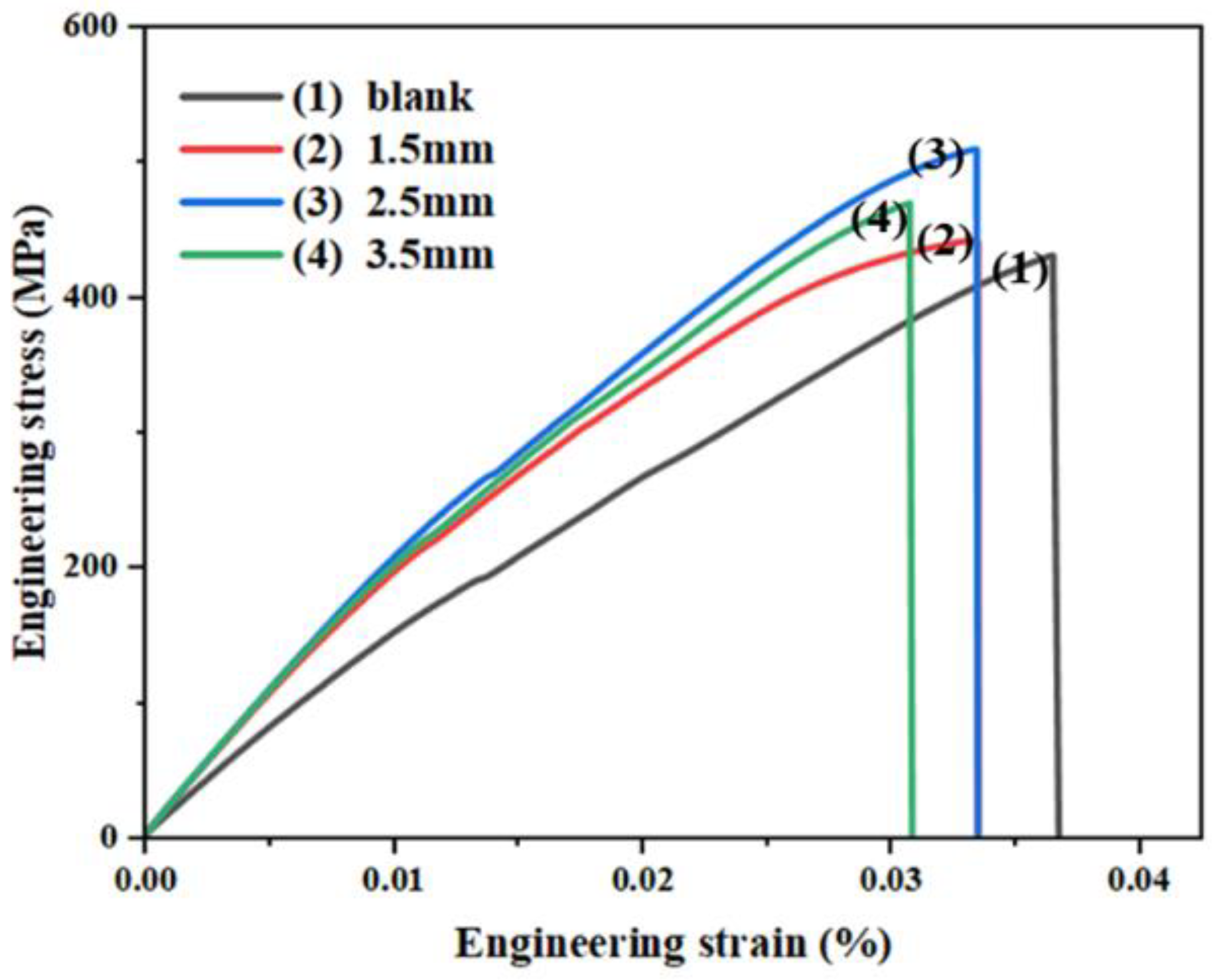
- Among the microstructure of the processed regions (units) with various spacings, compared to 1.5 mm and 3.5 mm, the strength and tensile properties of the biomimetic samples with 2.5 mm spacing were the best, and the UTS increased by 15% compared with the lowest processed sample of 1.5 mm.
- (3)
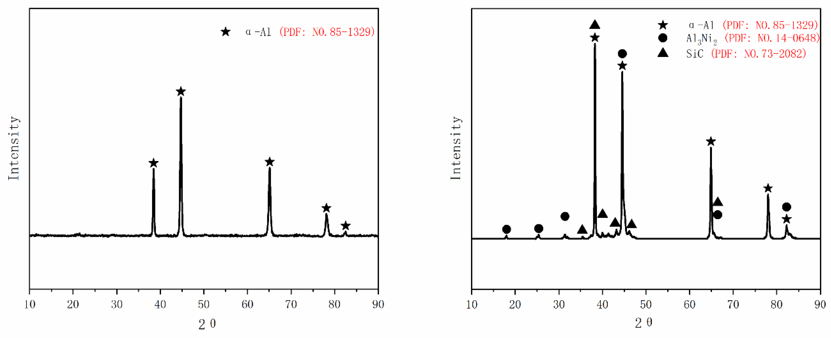
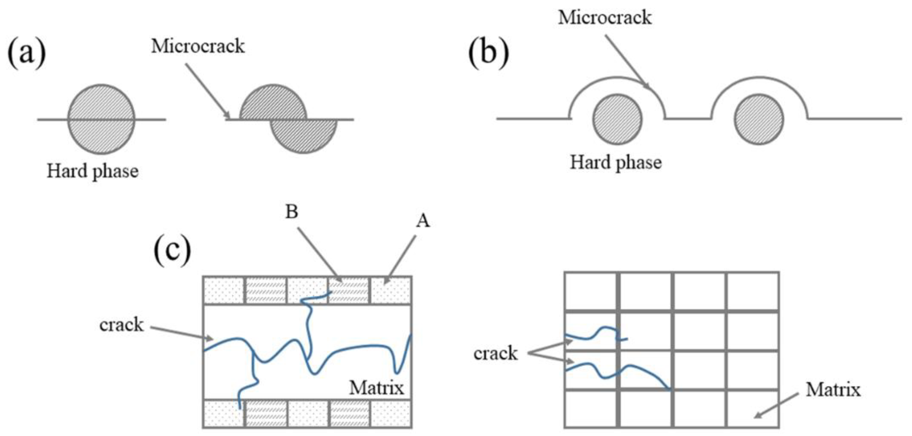
- Among the microstructure of the processed regions (units) with various spacings, compared to 1.5 mm and 3.5 mm, the “soft-hard” interphase structure in the 2.5 mm spacing reticulation design played an excellent role in slowing down the stress on the matrix, to avoid stress concentrated in low strength areas during the loading process, and the fracture damage between the unit and the matrix was minimal. In addition, the cross-junction region of the reticulate unit played a major role in inhibiting the initiation and the growth of cracks; the ability mainly depended on the uniformity of the microstructure and the distribution of the Al3Ni2 hard phases.
Author Contributions
Funding
Data Availability Statement
Conflicts of Interest
References
- Zhou, Y.; Zhuo, C.F.; Deng, F. Can the rise of the manufacturing value chain be the driving force of energy conservation and emission reduction in China. Energy Policy 2021, 156, 112408. [Google Scholar] [CrossRef]
- Han, C. Research on the development and application of lightweight automotive materials. J. Phys. Conf. Ser. 2020, 1676, 012085. [Google Scholar] [CrossRef]
- Lu, J.; Song, Y.; Hua, L.; Zheng, K.; Dai, D. Thermal deformation behavior and processing maps of 7075 aluminum alloy sheet based on isothermal uniaxial tensile tests. J. Alloys Compd. 2018, 767, 856–869. [Google Scholar] [CrossRef]
- Otani, Y.; Sasaki, S. Effects of the addition of silicon to 7075 aluminum alloy on microstructure, mechanical properties, and selective laser melting process ability. Mater. Sci. Eng. A 2020, 777, 139079. [Google Scholar] [CrossRef]
- Lei, Z.; Bi, J.; Chen, Y.; Chen, X.; Qin, X.; Tian, Z. Effect of energy density on formability, microstructure and micro-hardness of selective laser melted Sc-and Zr-modified 7075 aluminum alloy. Powder Technol. 2019, 356, 594–606. [Google Scholar] [CrossRef]
- Li, Y.-X.; Zhang, P.-F.; Bai, P.-K.; Zhao, Z.-Y.; Liu, B. Analysis of geometrical characteristics and properties of laser cladding 85 wt.% Ti+ 15 wt.% TiBCN powder on 7075 aluminum alloy substrate. Materials 2018, 11, 1551. [Google Scholar] [CrossRef] [PubMed]
- Bi, J.; Lei, Z.; Chen, Y.; Chen, X.; Tian, Z.; Liang, J.; Zhang, X.; Qin, X. Microstructure and mechanical properties of a novel Sc and Zr modified 7075 aluminum alloy prepared by selective laser melting. Mater. Sci. Eng. A 2019, 768, 138478. [Google Scholar] [CrossRef]
- Xu, Z.; Wang, D.; Song, W.; Tang, C.; Sun, P.; Yang, J.; Hu, Q.; Zeng, X. Microstructure and Wear of W-Particle-Reinforced Al Alloys Prepared by Laser Melt Injection. Micromachines 2022, 13, 699. [Google Scholar] [CrossRef]
- Wang, X.; Lei, L.; Yu, H. A review on microstructural features and mechanical properties of wheels/rails cladded by laser cladding. Micromachines 2021, 12, 152. [Google Scholar] [CrossRef]
- Zhu, Y.; Zhou, H.; Chen, Z.; Wang, Z.; He, F.; Xu, C. Study on Microstructure and Properties of Ni60A/WC Composite Coating by Alternating-Magnetic-Field-Assisted Laser Cladding. Micromachines 2022, 13, 653. [Google Scholar] [CrossRef]
- Li, Y.; Zhang, P.; Bai, P.; Wu, L.; Liu, B.; Zhao, Z. Microstructure and properties of Ti/TiBCN coating on 7075 aluminum alloy by laser cladding. Surf. Coat. Technol. 2018, 334, 142–149. [Google Scholar] [CrossRef]
- Yue, T.M.; Huang, K.J.; Man, H.C. In situ laser cladding of Al2O3 bearing coatings on aluminum alloy 7075 for improvement of wear resistance. Surf. Eng. 2007, 23, 142–146. [Google Scholar] [CrossRef]
- Su, W.; Zhou, T.; Zhang, P.; Zhou, H.; Li, H.; Sui, Q. Effect of the orientation of laser stripes on the abrasion resistance of biomimetic laser textured surfaces. Opt. Laser Technol. 2018, 107, 380–388. [Google Scholar] [CrossRef]
- Sui, Q.; Zhou, H.; Yang, L.; Liang, G.; Zhang, H.; Zhang, P.; Chen, Z. Lubricating property of cast iron combined with two-scale unit structure by biomimetic laser treatment. Tribol. Int. 2018, 117, 180–188. [Google Scholar] [CrossRef]
- Yuan, Y.; Zhao, G.; Zhang, P.; Zhou, H. Effects of shapes of biomimetic coupling units on wear resistance of 7075 aluminum alloy. Opt. Laser Technol. 2020, 121, 105786. [Google Scholar] [CrossRef]
- Zhang, J.; Song, B.; Wei, Q.; Bourell, D.; Shi, Y. A review of selective laser melting of aluminum alloys: Processing, microstructure, property and developing trends. J. Mater. Sci. Technol. 2019, 35, 270–284. [Google Scholar] [CrossRef]
- Zhao, G.; Yuan, Y.; Zhang, P.; Zang, C.; Zhang, J.; Tao, L.; Zhang, G.; Zhou, H. Effects of laser-processed unit distribution density on wear resistance of biomimetic 6082 aluminum alloy. Opt. Laser Technol. 2019, 112, 175–182. [Google Scholar] [CrossRef]
- Zhao, G.; Yuan, Y.; Zhang, P.; Zhou, T.; Zhou, H. Influence of orientations biomimetic units processed by laser on wear resistance of 6082 aluminum alloy. Opt. Laser Technol. 2020, 127, 106196. [Google Scholar] [CrossRef]
- Chai, Q.; Fang, C.; Qiu, X.; Xing, Y.; Sun, G. Modeling of temperature field and profile of Ni60AA formed on cylindrical 316 stainless steel by laser cladding. Surf. Coat. Technol. 2021, 428, 127865. [Google Scholar] [CrossRef]
- Lei, L. Microstructure and Properties of Laser Clad Ni Al Composite Coating on Aluminum Alloy Surface; School of Materials Science and Engineering, Chongqing University of Technology: Chongqing, China, 2018. [Google Scholar]
- Lei, L.; Ye, H.; Song, K.; Lu, X.; Zheng, J.; Ou, L.; Feng, K. Effect of Al2O3-TiO2 on Microstructure and Properties of NiAl Coating by Laser Cladding on Aluminum Alloy. Surf. Technol. 2018, 47, 145–150. [Google Scholar]
- Tian, Y.; Li, L.; Li, J.; Yang, Y.; Li, S.; Qin, G. Correlating Strength and Hardness of High-Entropy Alloys. Adv. Eng. Mater. 2021, 23, 2001514. [Google Scholar] [CrossRef]
- Sharma, N.K.; Misra, R.K.; Sharma, S. Modeling of thermal expansion behavior of densely packed Al/SiC composites. Int. J. Solids Struct. 2016, 102, 77–88. [Google Scholar] [CrossRef]


| Component | Zn | Mg | Cu | Cr | Fe | Si | Mn | Ti | Al |
|---|---|---|---|---|---|---|---|---|---|
| Content | 5.53 | 2.63 | 1.51 | 0.22 | 0.16 | 0.06 | 0.04 | 0.03 | Bal |
| Sample | UTS, MPa | EL, % |
|---|---|---|
| blank | ||
| 1.5 mm | ||
| 2.5 mm | ||
| 3.5 mm |
Disclaimer/Publisher’s Note: The statements, opinions and data contained in all publications are solely those of the individual author(s) and contributor(s) and not of MDPI and/or the editor(s). MDPI and/or the editor(s) disclaim responsibility for any injury to people or property resulting from any ideas, methods, instructions or products referred to in the content. |
© 2023 by the authors. Licensee MDPI, Basel, Switzerland. This article is an open access article distributed under the terms and conditions of the Creative Commons Attribution (CC BY) license (https://creativecommons.org/licenses/by/4.0/).
Share and Cite
Sui, Q.; Cheng, D.; Dong, Y.; Ma, Y.; Su, Y.; Hu, N.; Sun, Z.; Chen, Y. Effect of Reticulate Unit Spacing on Microstructure and Properties of Biomimetic 7075 Aluminum Alloy by Laser Cladding. Micromachines 2023, 14, 418. https://doi.org/10.3390/mi14020418
Sui Q, Cheng D, Dong Y, Ma Y, Su Y, Hu N, Sun Z, Chen Y. Effect of Reticulate Unit Spacing on Microstructure and Properties of Biomimetic 7075 Aluminum Alloy by Laser Cladding. Micromachines. 2023; 14(2):418. https://doi.org/10.3390/mi14020418
Chicago/Turabian StyleSui, Qi, Danyang Cheng, Yingfei Dong, Yijia Ma, Yingrui Su, Ning Hu, Zexuan Sun, and Yuanbo Chen. 2023. "Effect of Reticulate Unit Spacing on Microstructure and Properties of Biomimetic 7075 Aluminum Alloy by Laser Cladding" Micromachines 14, no. 2: 418. https://doi.org/10.3390/mi14020418
APA StyleSui, Q., Cheng, D., Dong, Y., Ma, Y., Su, Y., Hu, N., Sun, Z., & Chen, Y. (2023). Effect of Reticulate Unit Spacing on Microstructure and Properties of Biomimetic 7075 Aluminum Alloy by Laser Cladding. Micromachines, 14(2), 418. https://doi.org/10.3390/mi14020418