Study on In-Situ Tool Wear Detection during Micro End Milling Based on Machine Vision
Abstract
:1. Introduction
2. Materials and Methods
2.1. Machining Parameters
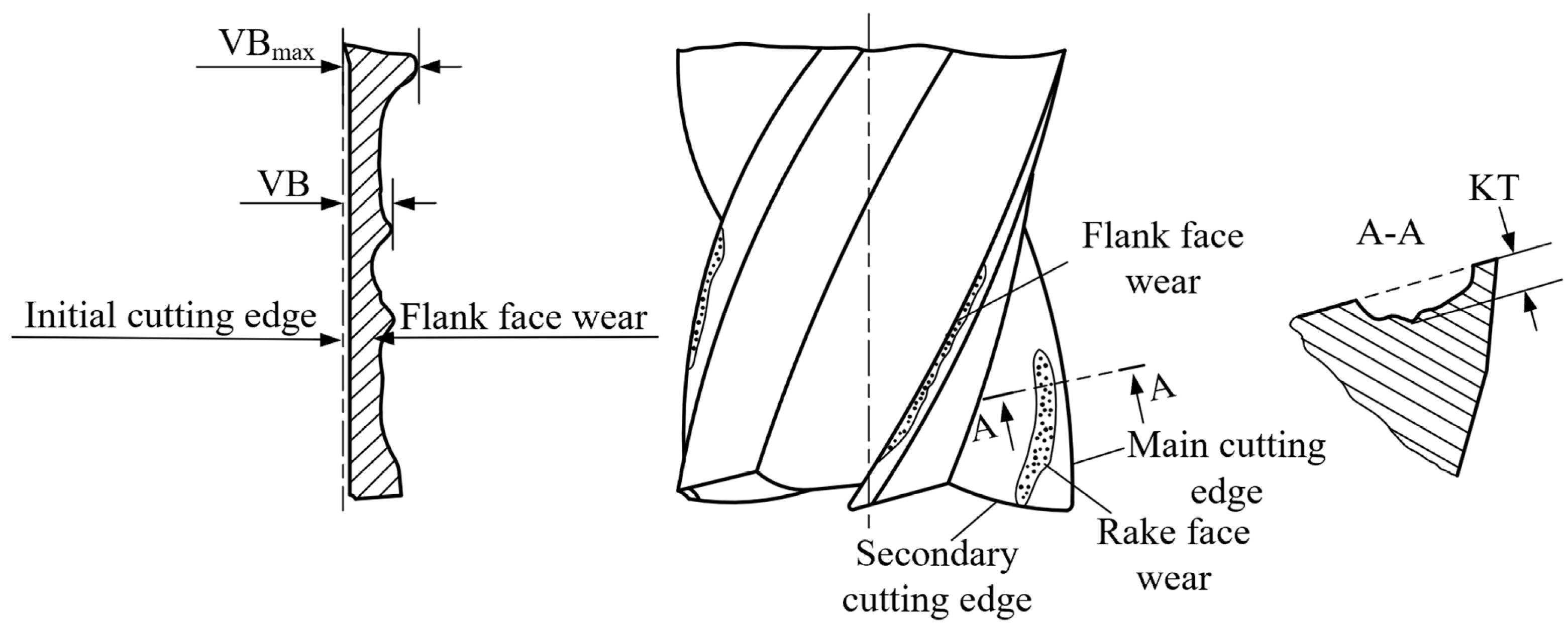
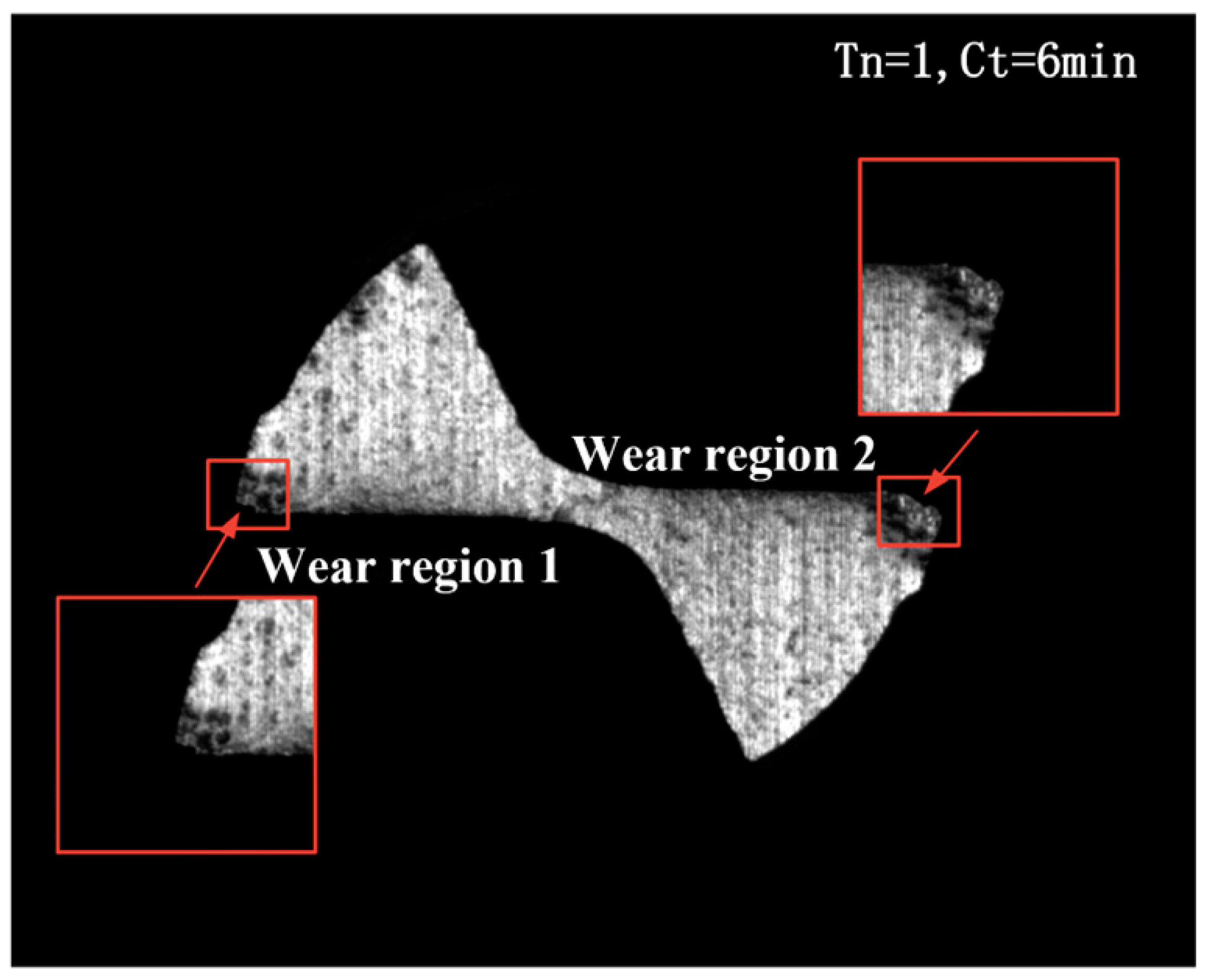
2.2. Types of Wear of Micro End Milling Cutter and Evaluation Indicator Selection
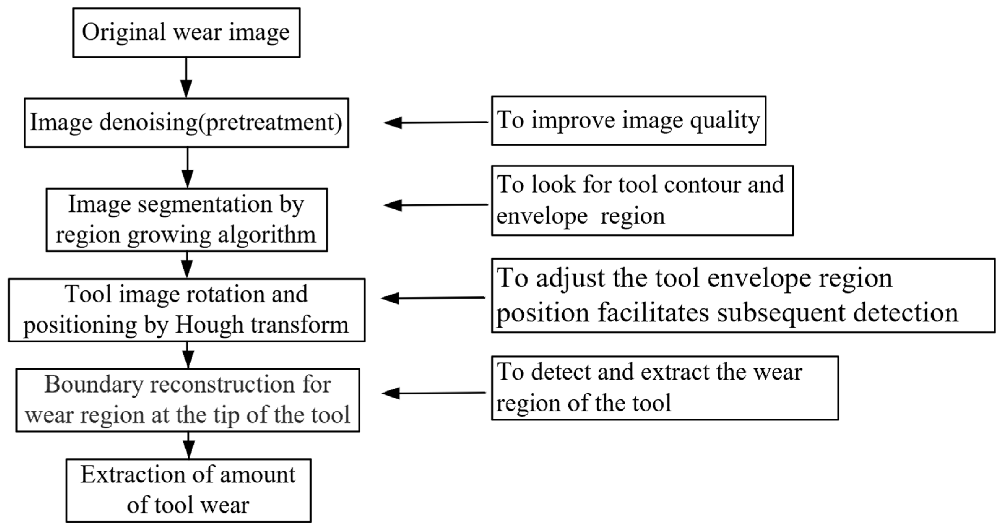
2.3. Tool Wear In-Situ Detection Image Processing Algorithm
2.3.1. Image Denoising (Image Pretreatment)
- (1)
- image acquisition
- (2)
- image transmission
2.3.2. Tool Wear Image Segmentation Based on Region Growing Method
- (1)
- Assume that the original tool wear image is , and threshold is S. The tool wear image was segmented to obtain a seed image .
- (2)
- To obtain a new seed image, pixels in that meet the following conditions were added to the seed region : (a) 8-connected neighborhood between pixels and seed points; (b) the absolute value of the gray level difference of pixels at and those in the original image corresponded by each seed point is less than or equal to the gray threshold T.
- (3)
- The region was iteratively grown by repeating Step (2) until no pixels that meet (a) and (b) can be picked to merge into the image. Then, the final segmented image was obtained.
2.3.3. Tool Rotation and Positioning Algorithm Based on Hough Transform
- (1)
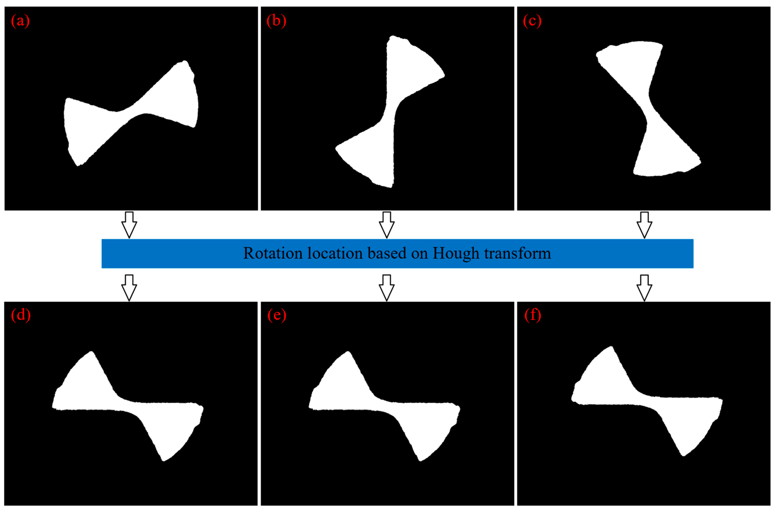
- Sobel edge detection was performed for the segmented image to obtain the tool boundary image.
- (2)
- Hough transform was used to detect the straight line of the cutting edge from the tool boundary image obtained in Step (1) to identify the angle of inclination of the cutting edge.
- (3)
- The micro end milling tool was rotated if necessary to a horizontal position to obtain a horizontal image of the cutting edge.
2.3.4. Boundary Reconstruction of Wear Region of Tool Tip
- (1)
- For the horizontal image of the cutting edge, Canny edge detection was used to detect the tool’s contour and extract the boundary of the tool.
- (2)
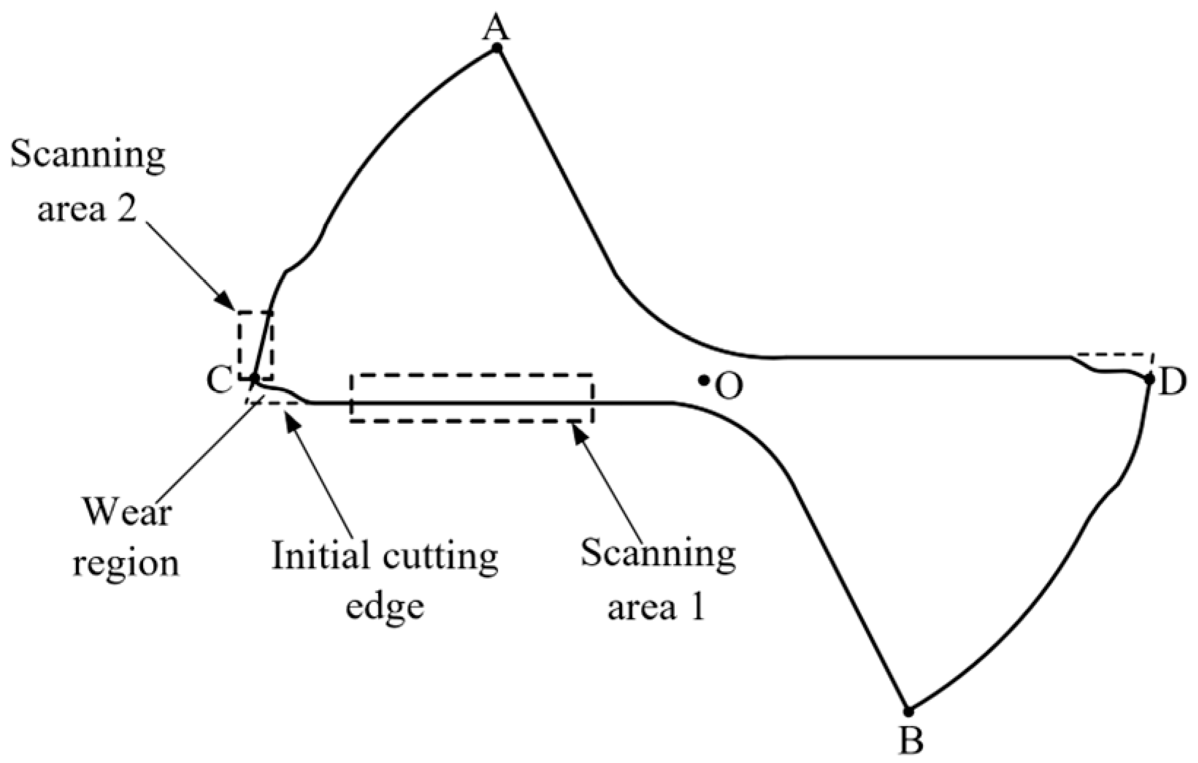
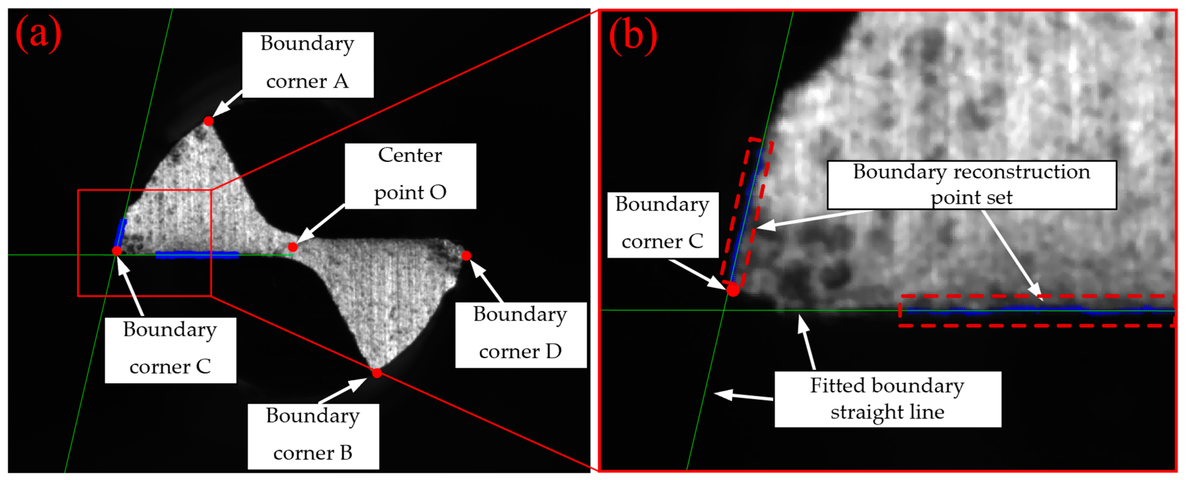
- The detected image was scanned through, row by row, from top to bottom until the pixel point with a value of 1 was identified. The coordinate point of the pixel was recorded, and it was the top corner A of the tool. Similarly, the bottom corner B was identified by scanning through the image, row by row from bottom to top.
- (3)
- The midpoint of A and B was computed based on the features of the tool, which was the central point O of the secondary flank face of the tool.
- (4)
- The boundary image extracted by Canny edge detector was scanned through, column by column from left to right, until the pixel with a value of 1 was identified. The coordinate point of the pixel was recorded, and it was the left corner C of the tool. Similarly, the right corner D was identified by scanning through the image column by column from right to left.
- (5)
- Taking O of the tool as the coordinate reference point to define the range of the column coordinate for scanning area 1. Within this target region, scanning was performed column by column from left to right, and from bottom to top for each column to locate the coordinate of the pixel with a value of 1 until coordinates of all points in scanning area 1 were obtained.
- (6)
- Taking O and C of the tool as the coordinate reference point to identify the area of the row coordinate for scanning area 2. The defined area was scanned through, row by row from top to bottom, and from left to right for each row to identify the coordinate of the pixel with a value of 1 until the coordinates of all points in scanning area 2 were obtained.
- (7)
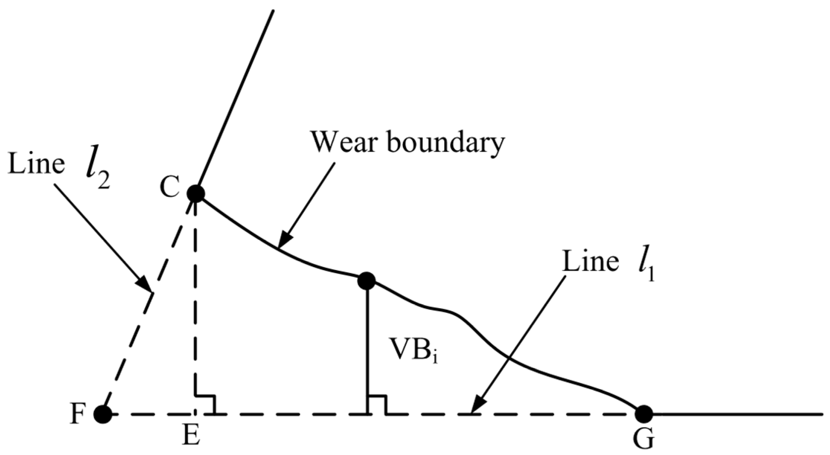
- All points in scanning area 1 obtained in Step (5) were fitted by least squares to get the equation of straight line , and the equation of straight line was obtained by fitting all points in scanning area 2 identified in Step (6) to the first-order polynomial by least squares.
2.3.5. Extraction of the Amount of Tool Wear
- Wear width and wear area
- 2.
- Reduction in diameter of bottom edge
3. Experimental Result and Analysis
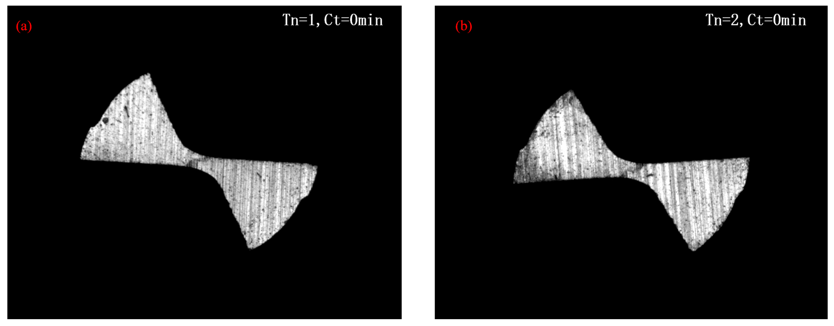
3.1. Actual Result Analysis for Tool Wear In-Situ Detection Algorithm
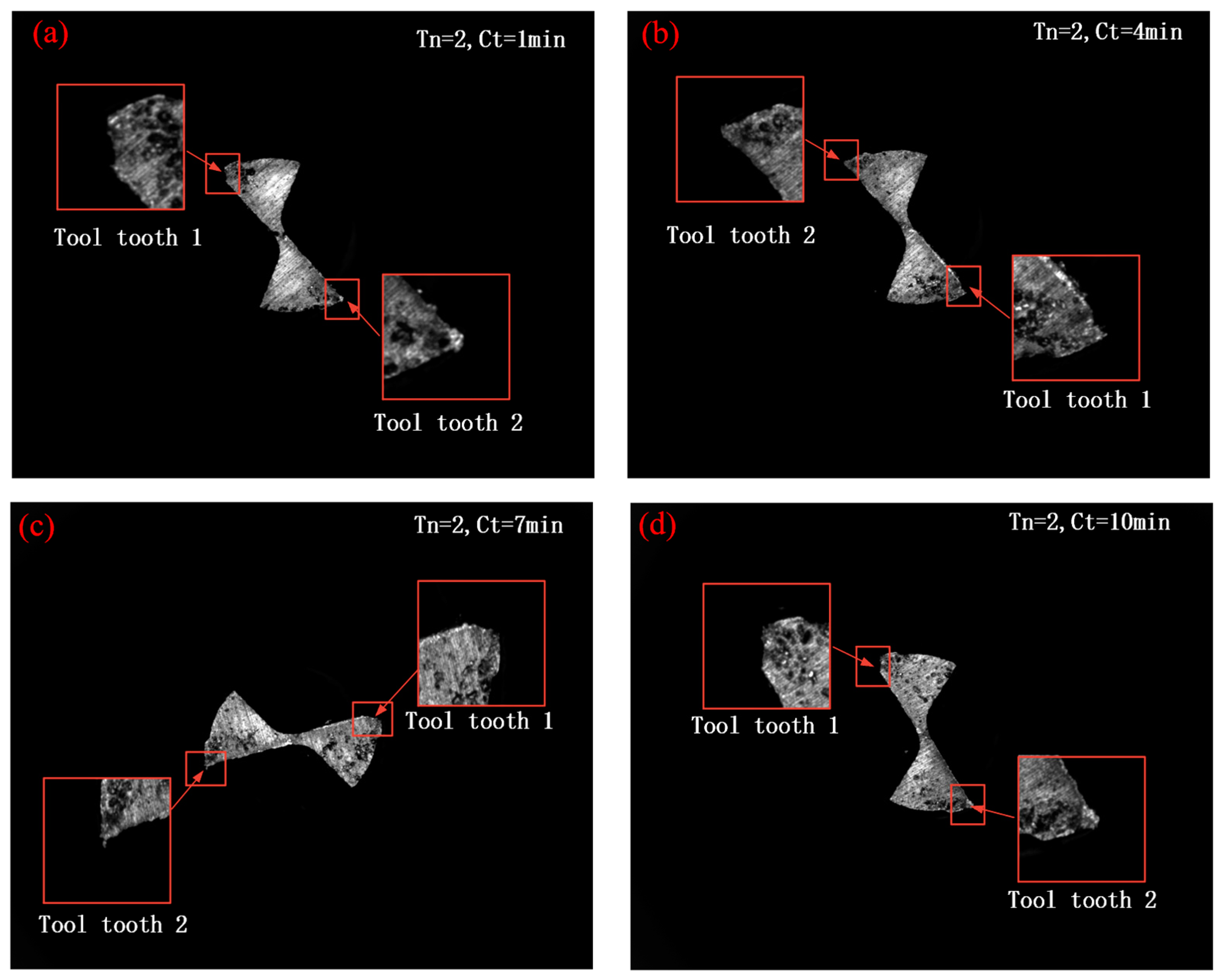
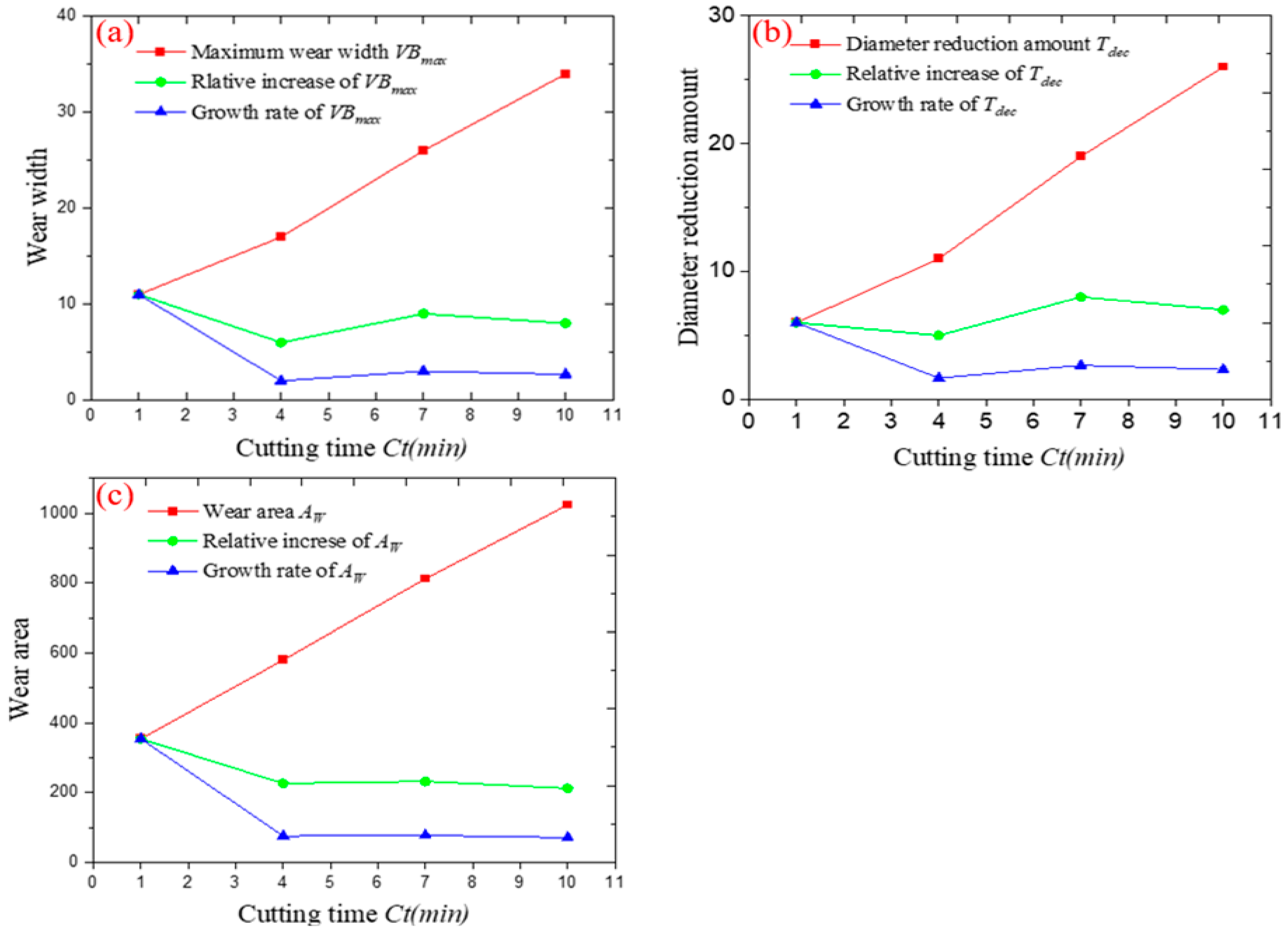
3.2. Tool Wear In-Situ Detection Result and Change Tendency Analysis during Micro End Milling
4. Conclusions
- (1)
- This paper firstly builds a micro milling tool wear image acquisition system based on machine vision design according to the in situ detection requirements, and then analyzes the wear morphological characteristics of micro end milling tools. By comparing the wear pattern with that of conventional size end mills, the corresponding evaluation indictors of the wear state of micro face milling tool are proposed as (1) wear area AW, (2) maximum width of wear , (3) diameter reduction Tdec.
- (2)
- Meanwhile, the corresponding image processing process and corresponding algorithm algorithms are proposed for the processing of the acquired tool wear template images, which are used to realize: 1. source image denoising; 2. segmentation and extraction of the tool contour and envelope region; 3. rotational positioning of the tool; 4. edge reconstruction of the tool wear region; 5. extraction and calculation of the wear amount, respectively. The detection function of the tool wear status evaluation indictors is realized by writing the corresponding computer program.
- (3)
- Then, the accuracy and reliability of the proposed algorithm and the preparation procedure were verified through the analysis of the results of the verification tool wear images, and the variation law of the wear amount of the micro end milling tool with the cutting time was obtained. By analyzing the law, it can be seen that the wear area AW is more effective for detecting the wear at the tool tip in the first cutting stage, and the wear width and diameter reduction Tdec can be used for detecting tool wear in the subsequent cutting stage.
- (4)
- Finally, in order to improve the accuracy when performing in situ detection of tool wear on micro end mills, two aspects can be investigated in future work: (1) Improving the relevant image processing algorithms to improve the accuracy of image detection; (2) Increasing the types of acquired signals and using artificial intelligence algorithms to establish the correspondence between images and the remaining signals to make the in situ monitoring of tool wear status more accurate.
Author Contributions
Funding
Institutional Review Board Statement
Informed Consent Statement
Data Availability Statement
Conflicts of Interest
References
- Yang, K. Research on Key Technologies of Microfabrication and Micro-Tooling; Harbin Institute of Technology: Harbin, China, 2012. [Google Scholar]
- Cao, Z. Fundamental Research on Microfabrication Machine Tools, Tools and Machining Mechanisms; Nanjing University of Aeronautics and Astronautics: Nanjing, China, 2008. [Google Scholar]
- Yang, K.; Bai, Q.S.; Liang, Y.C.; Wang, B.; Sun, Y.Z.; Zhao, Y. Damage of micro-diameter cutter while micro-milling HPb63-3 lead brass. J. Tribol. 2008, 28, 448–452. [Google Scholar]
- Yang, H.B.; Zhao, F.; Zhu, N.; Gao, Z.C.; Feng, C.F. Application of deep convolutional neural network in tool wear monitoring under multiple working conditions. Mach. Tools Hydraul. 2021, 49, 69–74. [Google Scholar]
- Huang, H.X.; Zhang, J.; Wang, H.L.; Wang, H.L.; Wang, S.; Zhang, X.X. Research on tool wear detection method based on 3-KMBS. Comb. Mach. Tools Autom. Mach. Technol. 2020, 560, 90–93. [Google Scholar]
- Zhuang, K.; Shi, Z.; Sun, Y.; Gao, Z.; Wang, L. Digital Twin-Driven Tool Wear Monitoring and Predicting Method for the Turning Process. Symmetry 2021, 13, 1438. [Google Scholar] [CrossRef]
- Prakash, M.; Kanthababu, M.; Kumar, A.A.J.; Arun, N.; Venkadesan, V.P. Identification of tool wear status and correlation of chip morphology in micro-end milling of mild steel (SAE 1017) using acoustic emission signal. IOP Conf. Ser. Mater. Sci. Eng. 2020, 912, 032066. [Google Scholar] [CrossRef]
- Jia, B.; Quan, Y.; Zhu, Z. A machine vision system for in-machine inspection of tool wear. China Test. 2014, 40, 60–63. [Google Scholar]
- Dai, Y.; Zhu, K. A machine vision system for micro-milling tool condition monitoring. Precis. Eng. 2018, 52, 183–191. [Google Scholar] [CrossRef]
- Hou, Q.; Sun, J.; Huang, P. A novel algorithm for tool wear online inspection based on machine vision. Int. J. Adv. Manuf. Technol. 2019, 101, 2415–2423. [Google Scholar] [CrossRef]
- Li, H.S.; Liu, X.L.; Yue, C.X.; Li, X.C.; Steven, Y.L.; Wang, L.H. Automatic recognition and detection system for cutter wear. Comput. Appl. 2021, 41 (Suppl. S1), 259–263. [Google Scholar]
- Lin, W.-J.; Chen, J.-W.; Jhuang, J.-P.; Tsai, M.-S.; Hung, C.-L.; Li, K.-M.; Young, H.-T. Integrating object detection and image segmentation for detecting the tool wear area on stitched image. Sci. Rep. 2021, 11, 19938. [Google Scholar] [CrossRef] [PubMed]
- Sui, S.C.; Feng, P.F. The influences of tool wear on Ti6Al4V cutting temperature and burn defect. Int. J. Adv. Manuf. Technol. 2016, 85, 2831–2838. [Google Scholar] [CrossRef]
- Kadam, B.J.; Mahajan, K.A. Optimization of cutting temperature in machining of titanium alloy using Response Surface Method, Genetic Algorithm and Taguchi method. Mater. Today Proc. 2021, 47, 6285–6290. [Google Scholar] [CrossRef]
- Xiong, L.; Yan, X.; Zhang, F. Fundamentals of Mechanical Manufacturing Technology; Huazhong University of Science and Technology Press: Wuhan, China, 2007. [Google Scholar]
- Lu, J.C.; Sun, J.N. Metal Cutting Principles and Tools, 5th ed.; Machinery Industry Press: Beijing, China, 2011. [Google Scholar]
- Yu, J.; Zou, Q. Fundamentals of Machine Building Technology, 2nd ed.; Machinery Industry Press: Beijing, China, 2009. [Google Scholar]
- Li, X.W.; Zhang, J.; Du, R.S.; Yang, S.Z. Research on wear land on major flank of end mills with small-diameter. Tool Technol. 2000, 34, 7–10. [Google Scholar]
- GB/T16460-2016; End Mills Life Test. China Standard Press: Beijing, China, 2016.
- Zhu, K.P.; Li, K.X.; Mei, T.; Shi, Y.G. Progress of cutting force modelling in micro-milling. J. Mech. Eng. 2016, 52, 20–34. [Google Scholar] [CrossRef]
- Shi, W. Microfabrication Technology; Machinery Industry Press: Beijing, China, 2011. [Google Scholar]
- Nakayama, K.; Tamura, K. Size Effect in Metal Cutting Force. J. Manuf. Sci. Eng. Trans. ASM 1968, 31, 240–249. [Google Scholar] [CrossRef]
- Ikawa, N.; Shimada, S.; Tanaka, H. Minimum thickness of cut in micromachining. Nanotechnology 1999, 3, 6. [Google Scholar] [CrossRef]
- Gonzalez, R.C.; Woods, R.E. Digital Image Processing, 3rd ed.; Electronic Industry Press: Beijing, China, 2011. [Google Scholar]
- Yang, D.; Zhao, B.; Long, Z. MATLAB Image Processing Examples in Detail; Tsinghua University Press: Beijing, China, 2013. [Google Scholar]
- He, Q. Research on the Theory and Technology of Tiny Size Precision Inspection Based on Computer Vision; Jilin University: Changchun, China, 2007. [Google Scholar]
- Guo, S.Y.; Zhai, W.J.; Tang, Q.; Zhu, Y.J. Combining hough transform and improved least squares method for line detection. Comput. Sci. 2012, 39, 196–200. [Google Scholar]
- Wang, W.; Wang, W.P.; Wang, J.Y. An algorithm for finding the smallest circle containing all points in a given point set. J. Softw. 2000, 11, 1237–1240. [Google Scholar]
- Li, H.J.; Zhang, X.P. Analysis and improvement of the minimum enclosing circle algorithm for discrete point sets. J. Graphol. 2012, 33, 34–38. [Google Scholar]
- Yu, T.Q.; Wang, Z.S.; Tian, X.Z.; Yu, H.D. Tool wear mechanisms in micro-milling of Ti6Al4V. J. Chang. Univ. Sci. Technol. 2017, 40, 32–37. [Google Scholar]








| Chemical Composition | Al | V | Fe | Si | O | C | N | Others |
|---|---|---|---|---|---|---|---|---|
| Specific weight | 5.5~6.5 | 3.5~4.5 | 0.25 | 0.15 | 0.13 | 0.08 | 0.05 | 0.512 |
| Machine Tool | Tool No. (Tn) | Spindle Speed (S r/min) | Axial Depth of Cut (ar mm) | Radial Depth of Cut (ae mm) | Feed Speed (F mm/min) | Cutting Time (Ct min) |
|---|---|---|---|---|---|---|
| Haas vertical machining center (VF-2SS) | 1 | 7000 | 0.02 | 0.500 | 500 | 6 |
| 2 | 7000 | 0.02 | 0.500 | 500 | 1,4,7,10 |
| Telecentric Lens Parameters | Industrial Camera Parameters | ||
|---|---|---|---|
| type | non-coaxial | resolution | 2448 × 2048 |
| magnification | 3 | sensor | 2/3-inch CMOS |
| type of lens mount | C | output interface | USB3.0 |
| distortion | <0.1% | frame rate | 79 fps |
| maximum compatible size of a camera | 2/3 inch | pixel size | 3.45 μm |
| depth of focus | 0.5 mm | type of lens mount | C |
| working distance | 65 mm | color | black and white |
| No. 2 Tool | Cutting Time | The Maximum Wear Width | Wear Area AW | Reduction in Diameter |
|---|---|---|---|---|
| 2 flute, TiN-coated carbide end mills with a diameter of 1 mm | 1 min | 11 | 354 | 6 |
| 4 min | 17 | 580 | 11 | |
| 7 min | 26 | 812 | 19 | |
| 10 min | 34 | 1024 | 26 |
Disclaimer/Publisher’s Note: The statements, opinions and data contained in all publications are solely those of the individual author(s) and contributor(s) and not of MDPI and/or the editor(s). MDPI and/or the editor(s) disclaim responsibility for any injury to people or property resulting from any ideas, methods, instructions or products referred to in the content. |
© 2022 by the authors. Licensee MDPI, Basel, Switzerland. This article is an open access article distributed under the terms and conditions of the Creative Commons Attribution (CC BY) license (https://creativecommons.org/licenses/by/4.0/).
Share and Cite
Zhang, X.; Yu, H.; Li, C.; Yu, Z.; Xu, J.; Li, Y.; Yu, H. Study on In-Situ Tool Wear Detection during Micro End Milling Based on Machine Vision. Micromachines 2023, 14, 100. https://doi.org/10.3390/mi14010100
Zhang X, Yu H, Li C, Yu Z, Xu J, Li Y, Yu H. Study on In-Situ Tool Wear Detection during Micro End Milling Based on Machine Vision. Micromachines. 2023; 14(1):100. https://doi.org/10.3390/mi14010100
Chicago/Turabian StyleZhang, Xianghui, Haoyang Yu, Chengchao Li, Zhanjiang Yu, Jinkai Xu, Yiquan Li, and Huadong Yu. 2023. "Study on In-Situ Tool Wear Detection during Micro End Milling Based on Machine Vision" Micromachines 14, no. 1: 100. https://doi.org/10.3390/mi14010100
APA StyleZhang, X., Yu, H., Li, C., Yu, Z., Xu, J., Li, Y., & Yu, H. (2023). Study on In-Situ Tool Wear Detection during Micro End Milling Based on Machine Vision. Micromachines, 14(1), 100. https://doi.org/10.3390/mi14010100


