
Kinetic Walking Energy Harvester Design for a Wearable Bowden Cable-Actuated Exoskeleton Robot

 ,
, 
Abstract
:1. Introduction
2. Knee Exoskeleton Design and Energy Flow Analysis
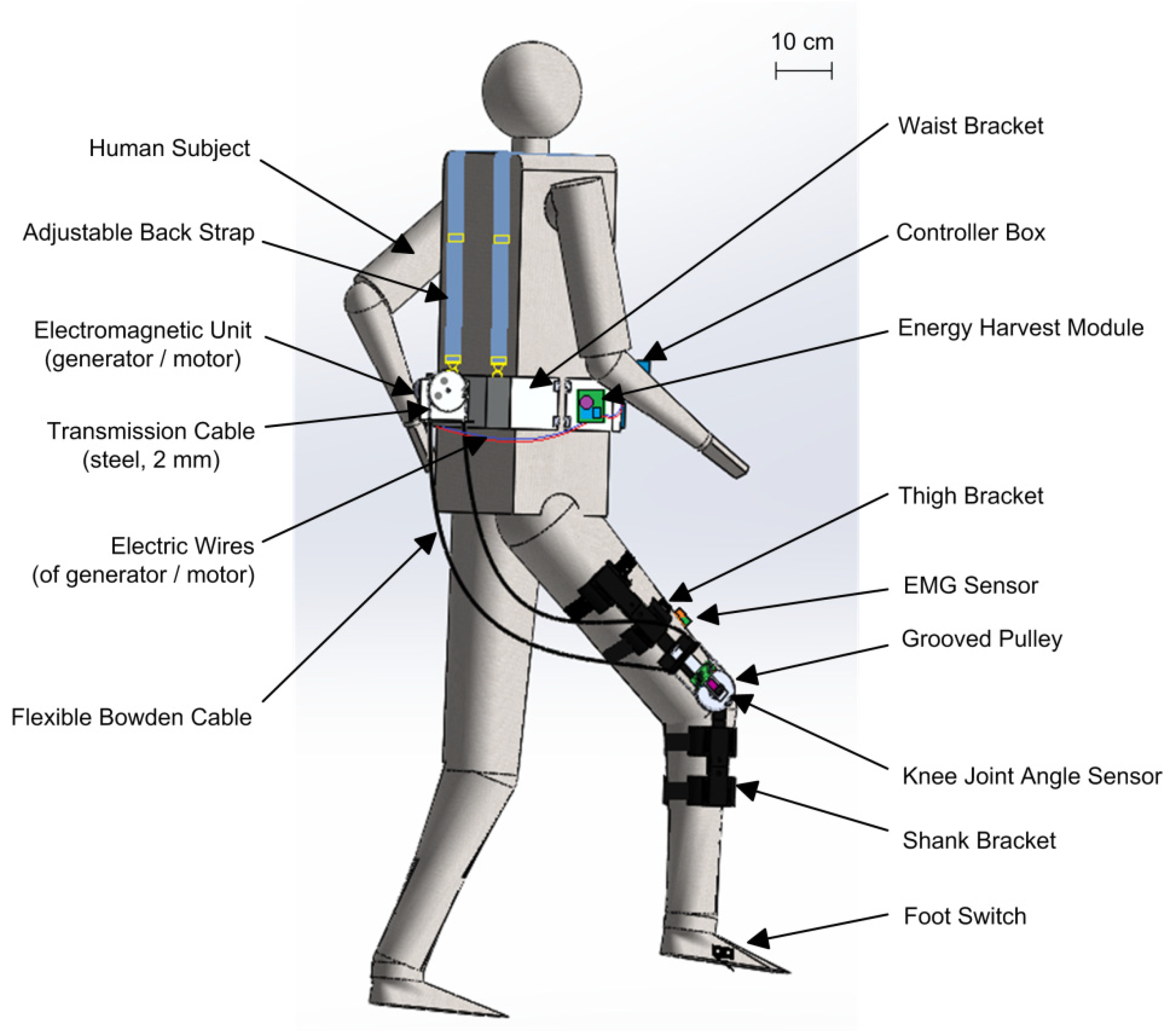
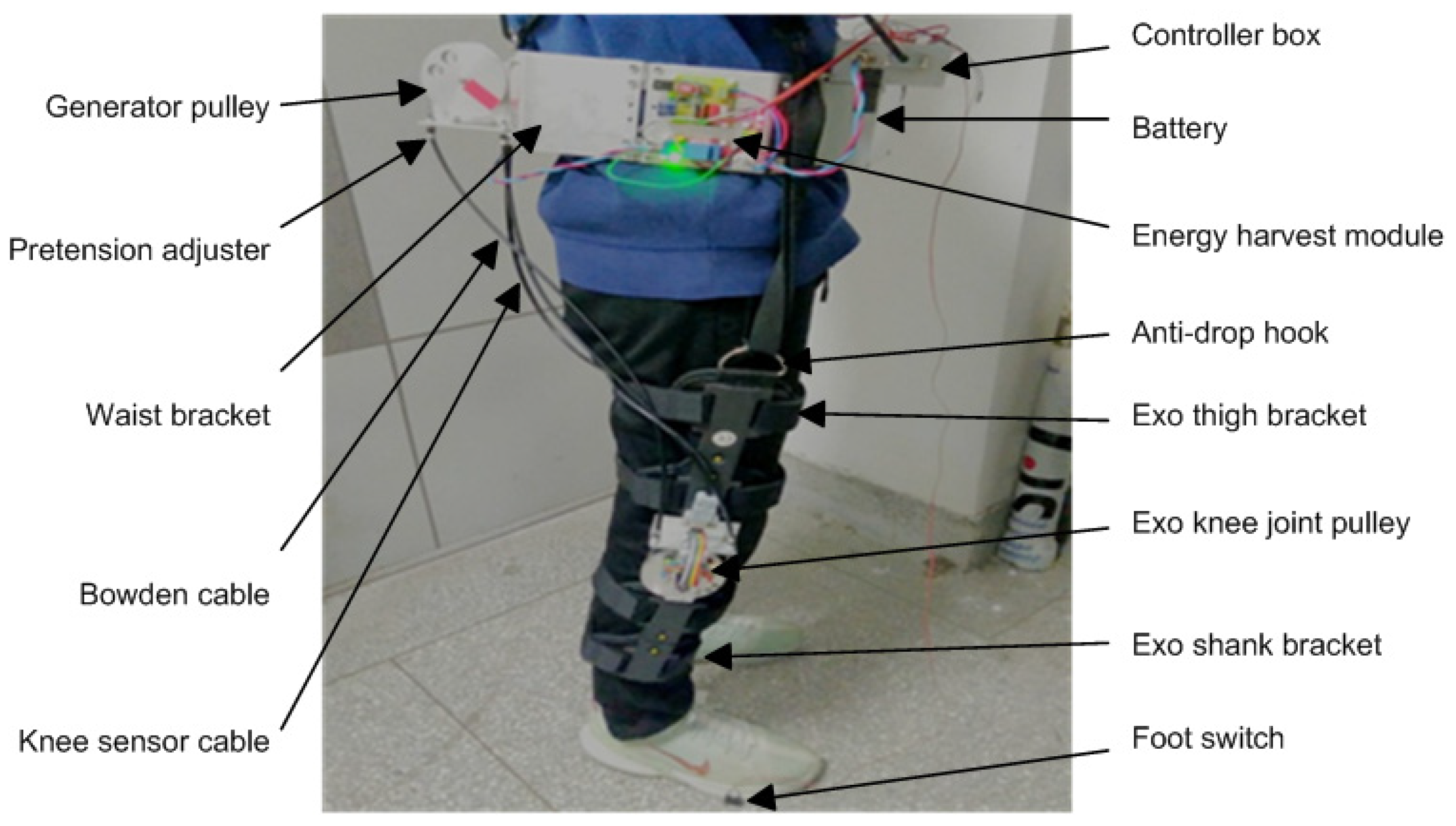
2.1. Structural Design of the Knee Exoskeleton
2.2. Energy Flow of the Limb-Exoskeleton System and Efficiency
3. Theoretical Modeling and Simulation
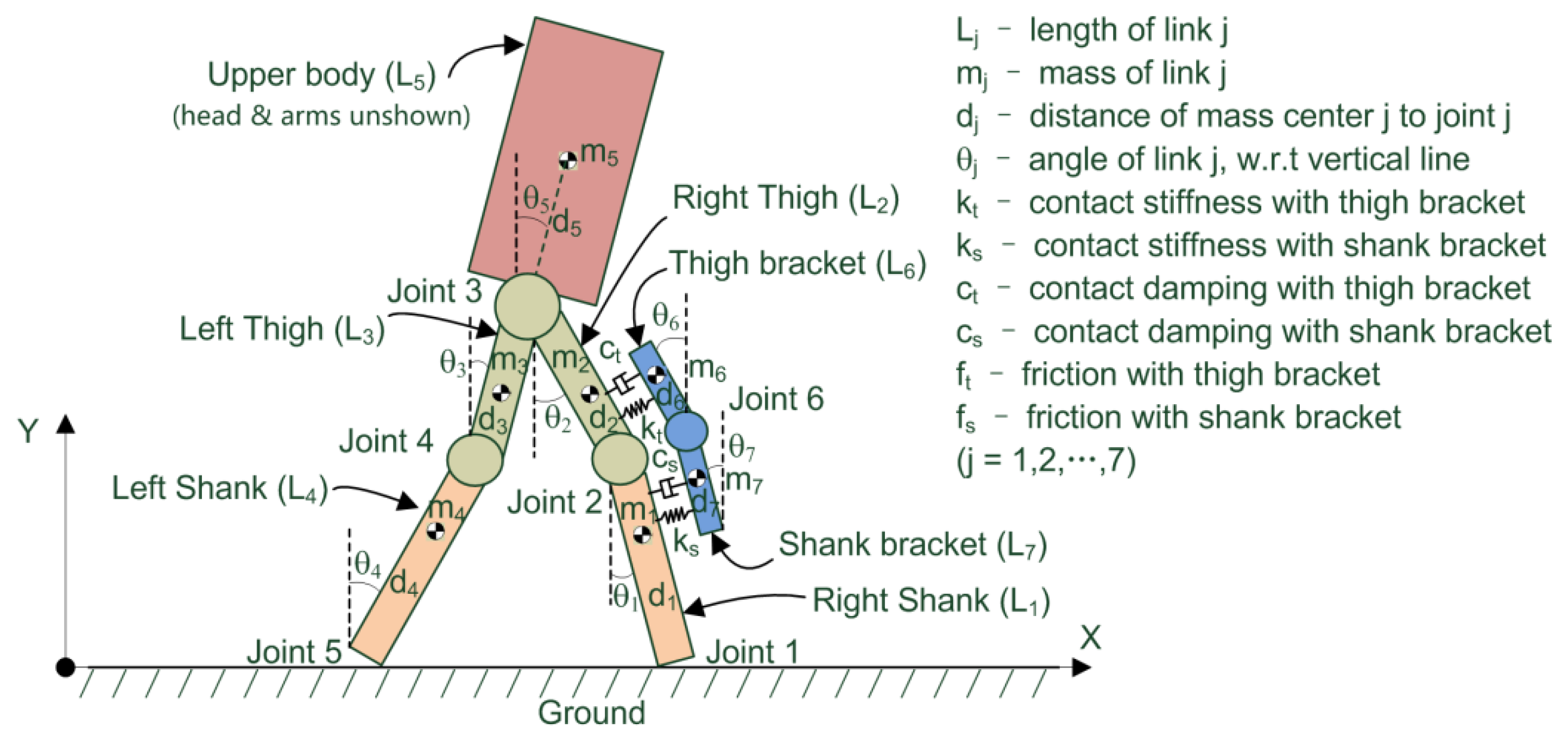
3.1. Dynamic Modeling of Human-Exoskeleton Motion
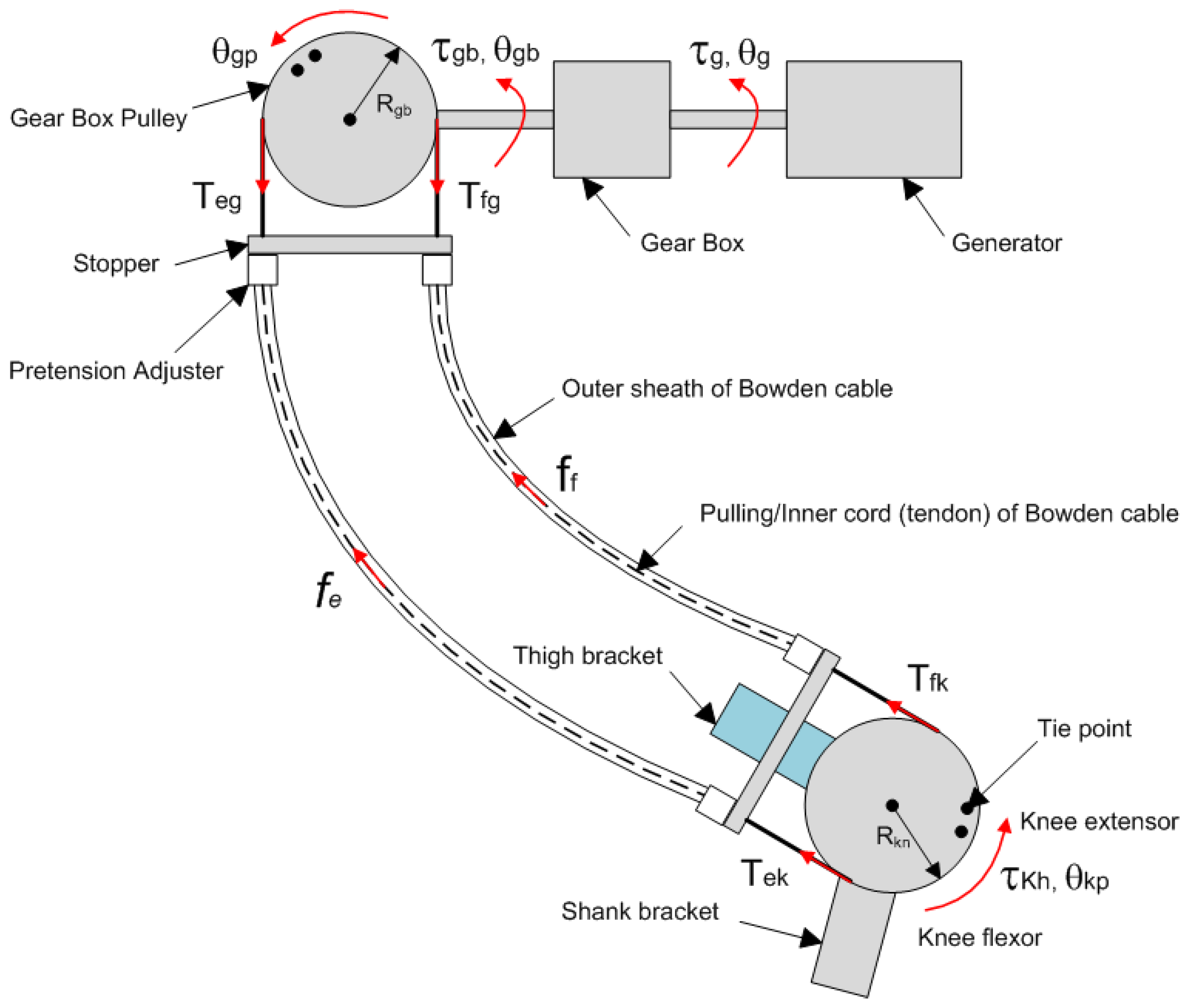
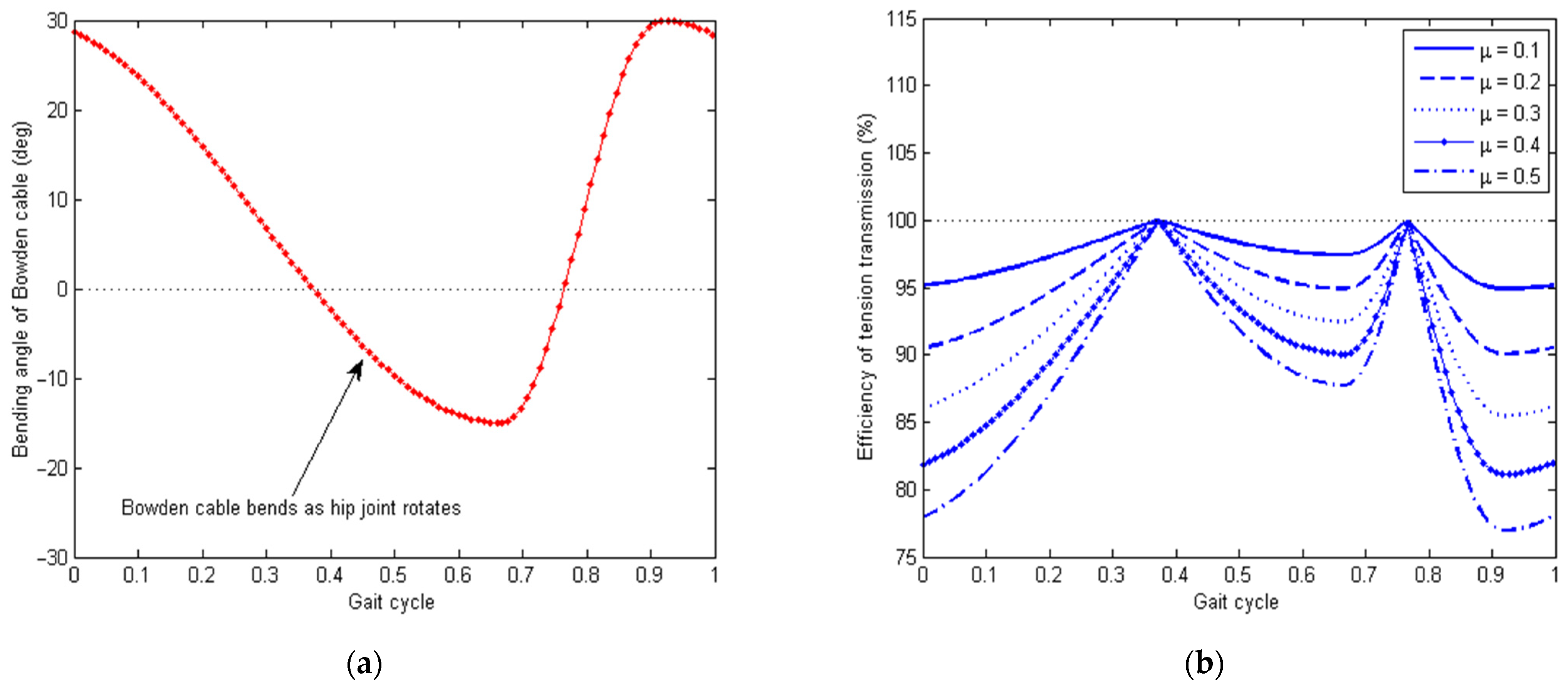
3.2. Transmission Characterization of the Bowden Cable Actuation System
3.3. Power Generation by the Knee Exoskeleton
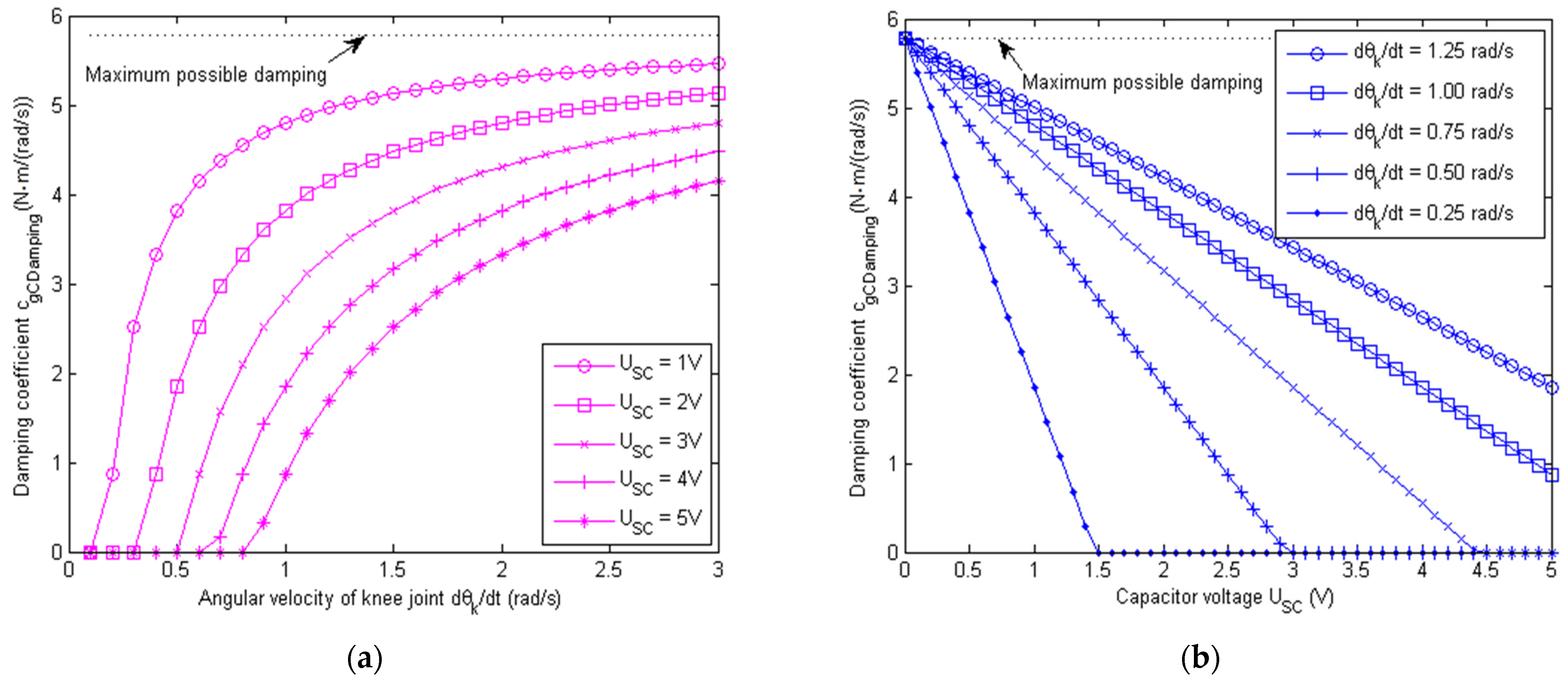
3.4. Impact Absorption Using Controlled Damping
4. Circuit Design for Energy Harvesting
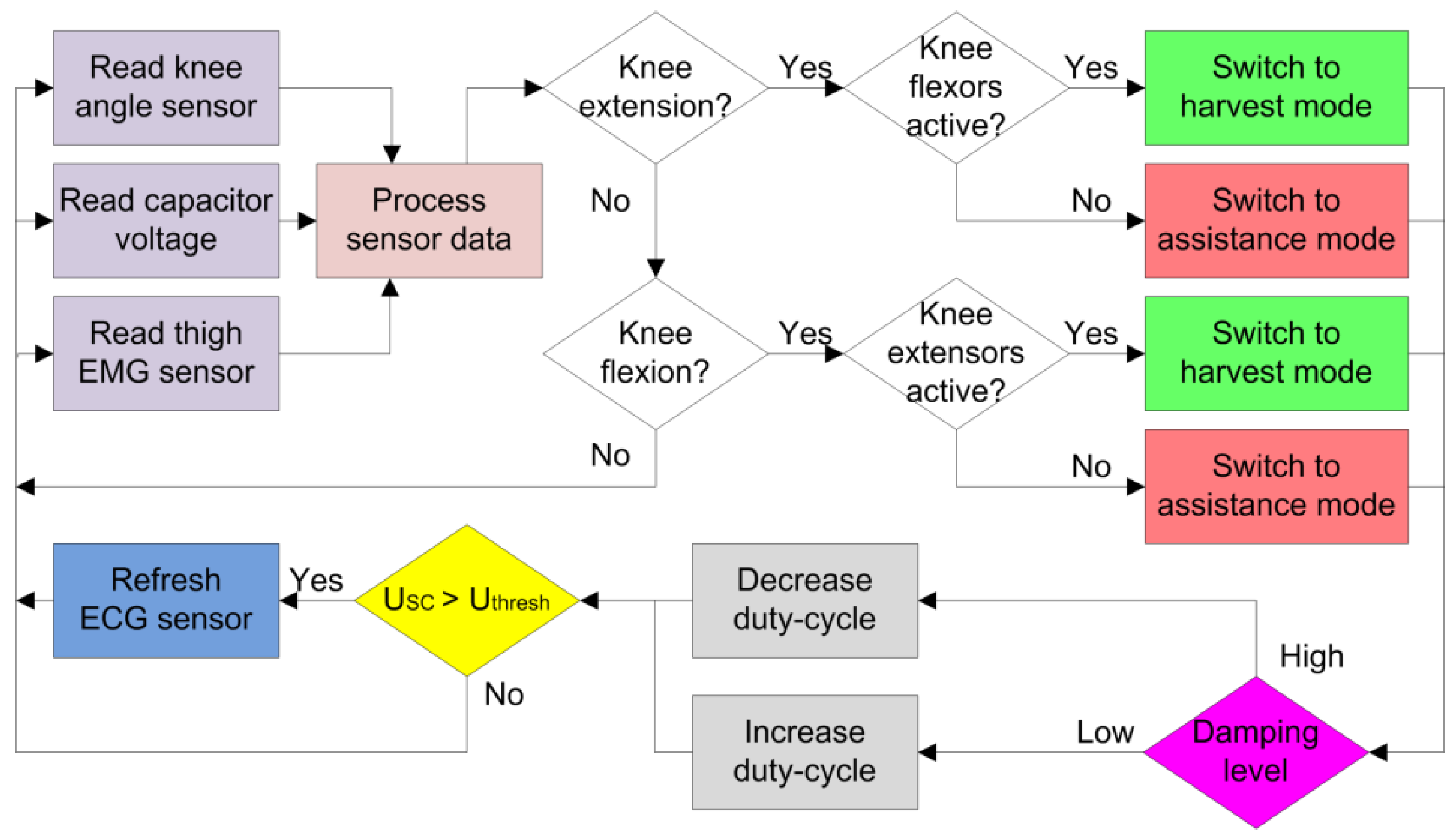
4.1. Mode Switching Criteria
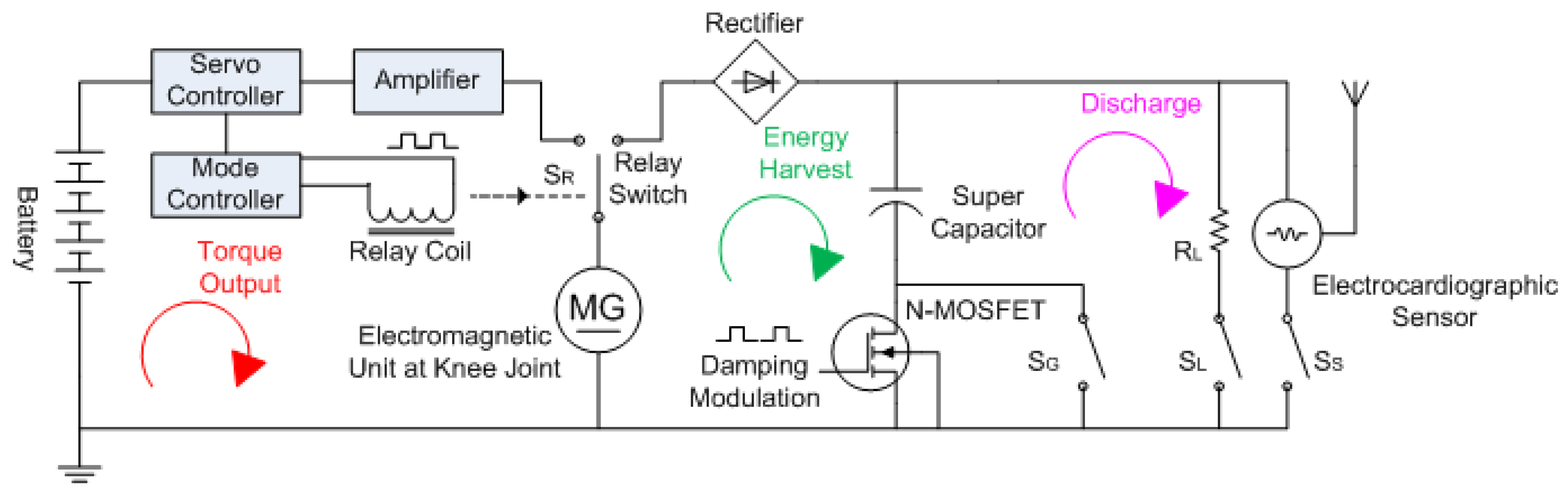
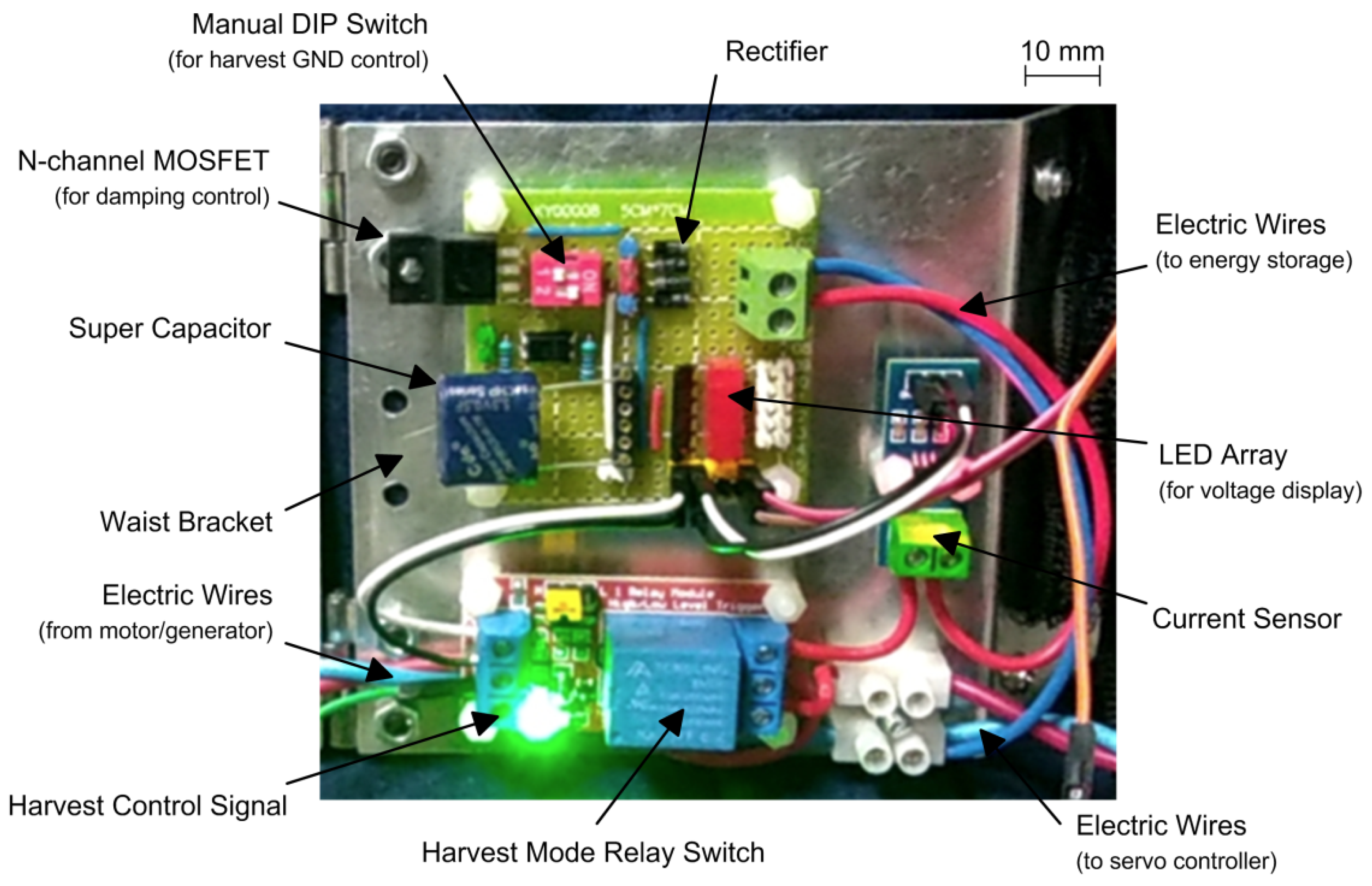
4.2. Control Circuit with Power Assistance, Energy Storage, and Discharge
5. Experimental Validation
5.1. Experimental Set-Up
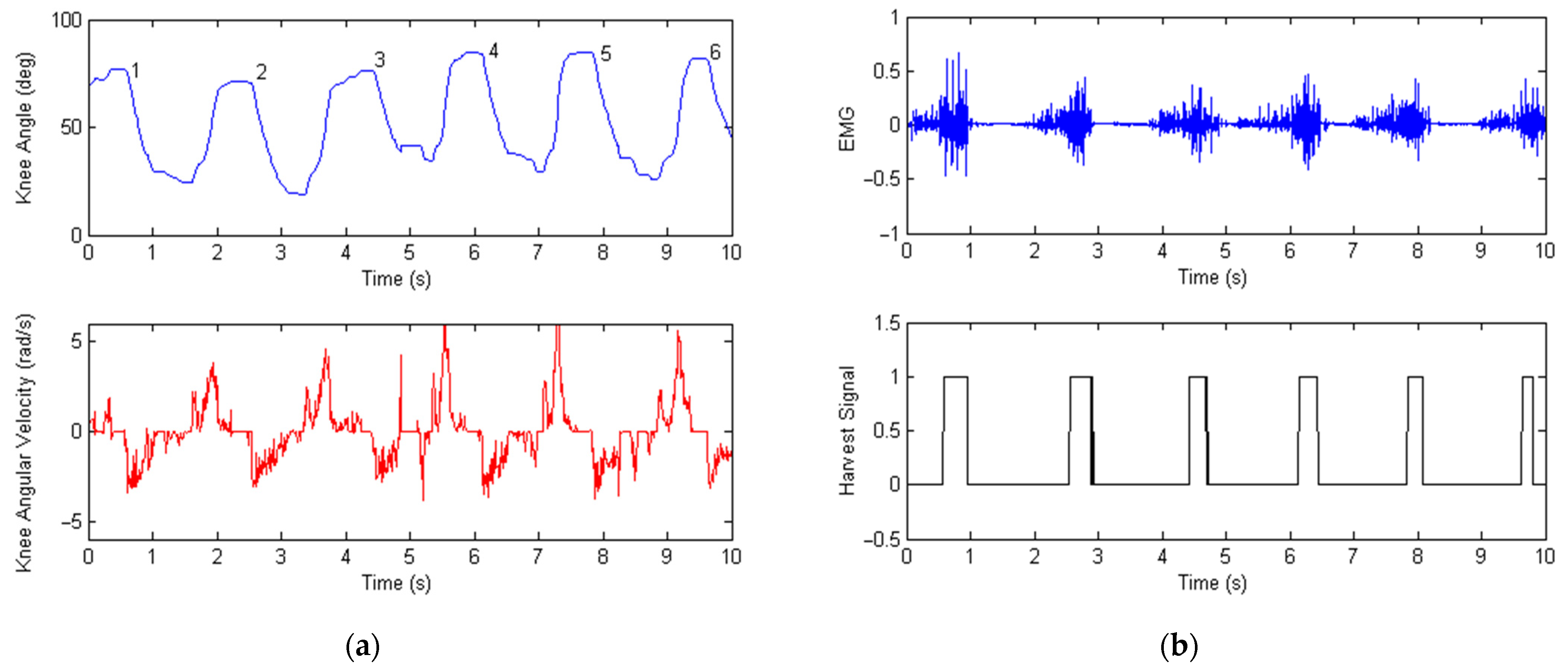
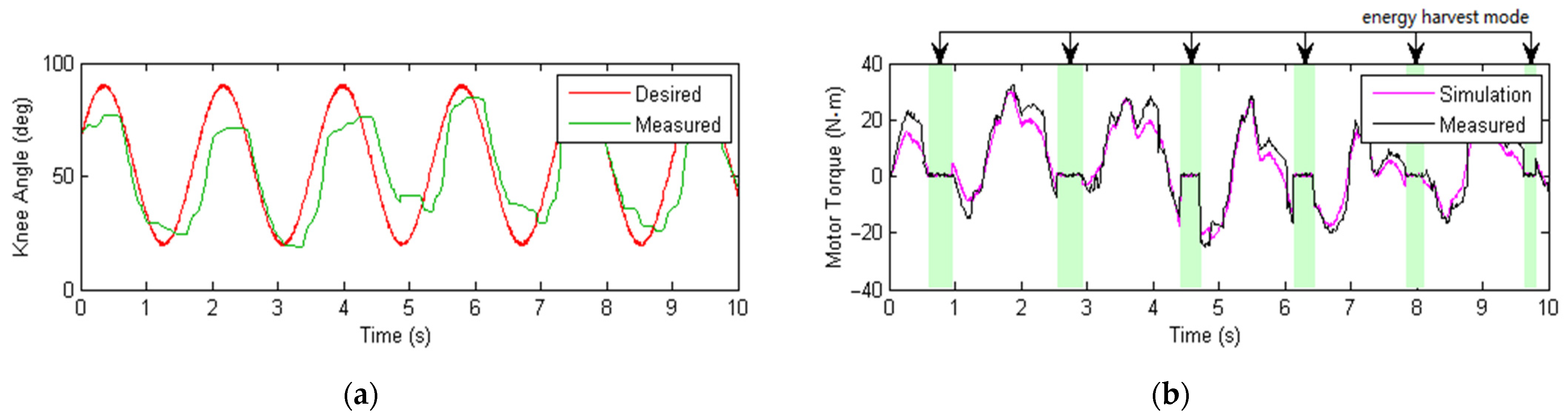
5.2. Experimental Tests and Data Measurements
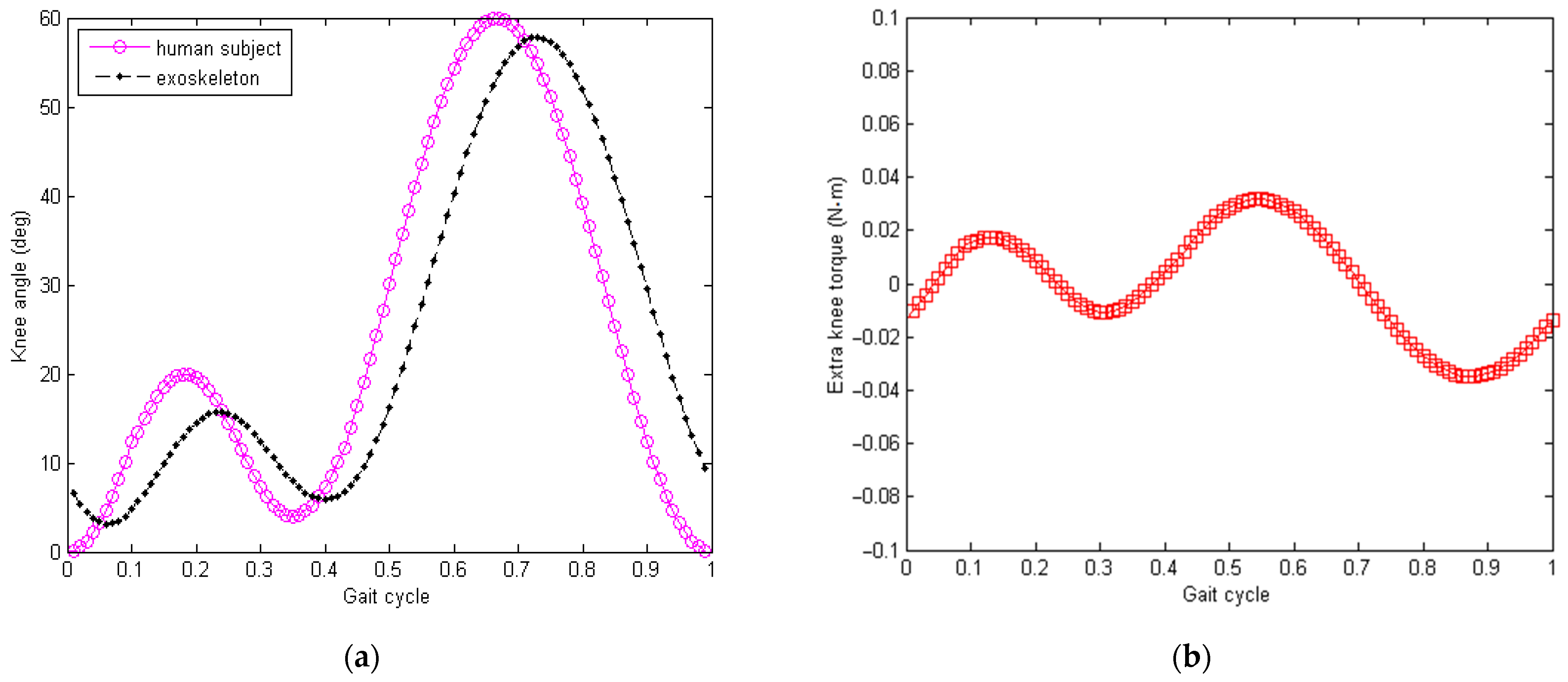
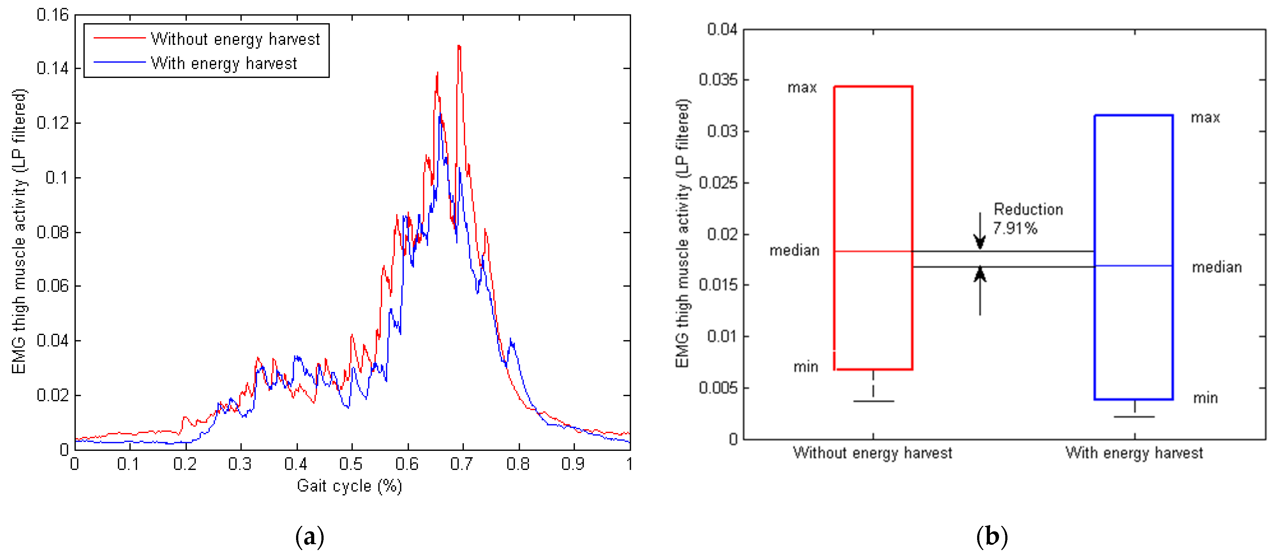
5.3. Analysis of Knee Torque Damping and Muscle Activity
6. Conclusions
Author Contributions
Funding
Institutional Review Board Statement
Informed Consent Statement
Data Availability Statement
Conflicts of Interest
References
- Zoss, A.B.; Kazerooni, H.; Chu, A. Biomechanical design of the Berkeley lower extremity exoskeleton (BLEEX). IEEE/ASME Trans. Mech. 2006, 11, 128–138. [Google Scholar] [CrossRef]
- Pratt, J.E.; Krupp, B.T.; Morse, C.J.; Collins, S.H. The RoboKnee: An exoskeleton for enhancing strength and endurance during walking. In Proceedings of the IEEE International Conference on Robotics and Automation, New Orleans, LA, USA, 26 April–1 May 2004; pp. 2430–2435. [Google Scholar]
- Park, Y.-L.; Santos, J.; Galloway, K.G.; Goldfield, E.C.; Wood, R.J. A soft wearable robotic device for active knee motions using flat pneumatic artificial muscles. In Proceedings of the IEEE International Conference on Robotics and Automation, Hong Kong, China, 31 May–5 June 2014; pp. 4805–4810. [Google Scholar]
- Malcolm, P.; Derave, W.; Galle, S.; Clercq, D. A simple exoskeleton that assists plantar flexion can reduce the metabolic cost of human walking. PLoS ONE 2013, 8, e56137. [Google Scholar]
- Mooney, L.M.; Rouse, E.J.; Herr, H.M. Autonomous exoskeleton reduces metabolic cost of human walking during load carriage. J. NeuroEng. Rehabil. 2014, 11, 80. [Google Scholar] [CrossRef] [PubMed] [Green Version]
- Norris, J.A.; Granata, K.P.; Mitros, M.R.; Byrne, E.M.; Marsh, A.P. Effect of augmented plantarflexion power on preferred walking speed and economy in young and older adults. Gait Posture 2007, 25, 620–627. [Google Scholar] [CrossRef]
- Yap, H.K.; Lim, J.H.; Nasrallah, F.; Goh, J.C.; Yeow, R.C. A soft exoskeleton for hand assistive and rehabilitation application using pneumatic actuators with variable stiffness. In Proceedings of the IEEE International Conference on Robotics and Automation, Seattle, WA, USA, 26–30 May 2015; pp. 4967–4972. [Google Scholar]
- Cha, Y.; Hong, J.; Lee, J.; Park, J.M.; Kim, K. Flexible Piezoelectric Energy Harvesting from Mouse Click Motions. Sensors 2016, 16, 1045. [Google Scholar] [CrossRef] [Green Version]
- Xie, J.; Wang, Y.; Dong, R.; Tao, K. Wearable Device Oriented Flexible and Stretchable Energy Harvester Based on Embedded Liquid-Metal Electrodes and FEP Electret Film. Sensors 2020, 20, 458. [Google Scholar] [CrossRef] [Green Version]
- Costa, M.S.; Manera, L.T.; Moreira, H.S. Study of the light energy harvesting capacity in indoor environments. In Proceedings of the 4th International Symposium on Instrumentation Systems, Circuits and Transducers, Sao Paulo, Brazil, 26–30 August 2019; pp. 1–4. [Google Scholar]
- Asama, J.; Burkhardt, M.R.; Davoodi, F.; Burdick, J.W. Investigation of energy harvesting circuit using a capacitor-sourced buck converter for a tubular linear generator of a moball: A spherical wind-driven exploration robot. In Proceedings of the IEEE Energy Conversion Congress and Exposition, Montreal, QC, Canada, 20–24 September 2015; pp. 316–3171. [Google Scholar]
- Tanwar, A.; Lal, S.; Razeeb, K.M. Structural Design Optimization of Micro-Thermoelectric Generator for Wearable Biomedical Devices. Energies 2021, 14, 2339. [Google Scholar] [CrossRef]
- Hyland, M.; Hunter, H.; Liu, J.; Veety, E. Wearable thermoelectric generators for human body heat harvesting. Appl. Energy 2016, 182, 518–524. [Google Scholar] [CrossRef] [Green Version]
- Shi, H.; Liu, Z.; Mei, Z. Overview of Human Walking Induced Energy Harvesting Technologies and Its Possibility for Walking Robotics. Energies 2020, 13, 86. [Google Scholar] [CrossRef] [Green Version]
- Choi, Y.M.; Lee, M.G.; Jeon, Y. Wearable Biomechanical Energy Harvesting Technologies. Energies 2017, 10, 1483. [Google Scholar] [CrossRef] [Green Version]
- Han, Y.; Cao, Y.; Zhao, J.; Yin, Y.; Ye, L.; Wang, X.; You, Z. A Self-Powered Insole for Human Motion Recognition. Sensors 2016, 16, 1502. [Google Scholar] [CrossRef] [PubMed] [Green Version]
- Wang, W.; Cao, J.; Yu, J.; Liu, R.; Bowen, C.; Liao, W.H. Self-Powered Smart Insole for Monitoring Human Gait Signals. Sensors 2019, 19, 5336. [Google Scholar] [CrossRef] [PubMed] [Green Version]
- Shull, P.; Xia, H. Modeling and Prediction of Wearable Energy Harvesting Sliding Shoes for Metabolic Cost and Energy Rate Outside of the Lab. Sensors 2020, 20, 6915. [Google Scholar] [CrossRef] [PubMed]
- Paradiso, J.; Starner, T. Energy scavenging for mobile and wireless electronics. IEEE Pervasive Comput. 2005, 4, 18–27. [Google Scholar] [CrossRef]
- Wang, Z.; Wu, X.; Zhang, Y.; Liu, Y.; Liu, Y.; Cao, W.; Chen, C. A New Portable Energy Harvesting Device Mounted on Shoes: Performance and Impact on Wearer. Energies 2020, 13, 3871. [Google Scholar] [CrossRef]
- Yang, L.; Xiong, C.; Hao, M.; Leng, Y.; Chen, K.; Fu, C. Energetic Response of Human Walking with Loads Using Suspended Backpacks. IEEE/ASME Trans. Mechatron. 2021, 1–12. [Google Scholar] [CrossRef]
- Li, X.; Meng, J.; Yang, C.; Zhang, H.; Zhang, L.; Song, R. A Magnetically Coupled Electromagnetic Energy Harvester with Low Operating Frequency for Human Body Kinetic Energy. Micromachines 2021, 12, 1300. [Google Scholar] [CrossRef]
- Dijk, W.; Kooij, H. A passive exoskeleton with artificial tendons: Design and experimental evaluation. In Proceedings of the IEEE International Conference on Rehabilitation Robot, Zurich, Switzerland, 29 June–1 July 2011; pp. 1–6. [Google Scholar]
- Xie, L.; Huang, G.; Huang, L.; Cai, S.; Li, X. An Unpowered Flexible Lower Limb Exoskeleton: Walking Assisting and Energy Harvesting. IEEE/ASME Trans. Mechatron. 2019, 24, 2236–2247. [Google Scholar] [CrossRef]
- Selinger, J.; Donelan, J. Myoelectric Control for Adaptable Biomechanical Energy Harvesting. IEEE Trans. Neural Syst. Rehabil. Eng. 2016, 24, 364–373. [Google Scholar] [CrossRef]
- Jiang, M.; Lu, Y.; Zhu, Z.; Jia, W. Advances in Smart Sensing and Medical Electronics by Self-Powered Sensors Based on Triboelectric Nanogenerators. Micromachines 2021, 12, 698. [Google Scholar] [CrossRef]
- Shaikh, M.O.; Huang, Y.B.; Wang, C.C.; Chuang, C.H. Wearable Woven Triboelectric Nanogenerator Utilizing Electrospun PVDF Nanofibers for Mechanical Energy Harvesting. Micromachines 2019, 10, 438. [Google Scholar] [CrossRef] [Green Version]
- Yin, L.; Kim, K.N.; Lv, J.; Tehrani, F.; Lin, M.; Lin, Z.; Moon, J.M.; Ma, J.; Yu, J.; Xu, S.; et al. A self-sustainable wearable multi-modular E-textile bioenergy microgrid system. Nat. Commun. 2020, 12, 1542. [Google Scholar] [CrossRef] [PubMed]
- Berdy, D.F.; Valentino, D.J.; Peroulis, D. Kinetic energy harvesting from human walking and running using a magnetic levitation energy harvester. Sens. Actuators A Phys. 2015, 222, 262–271. [Google Scholar] [CrossRef]
- Magno, M.; Spadaro, L.; Singh, J. Kinetic energy harvesting: Toward autonomous wearable sensing for Internet of Things. In Proceedings of the IEEE International Symposium on Power Electronics, Electrical Drives, Automation and Motion, Capri, Italy, 22–24 June 2016; pp. 248–254. [Google Scholar]
- Gljušćić, P.; Zelenika, S.; Blažević, D.; Kamenar, E. Kinetic Energy Harvesting for Wearable Medical Sensors. Sensors 2019, 19, 4922. [Google Scholar] [CrossRef] [PubMed] [Green Version]
- Jia, D.; Liu, J.; Zhou, Y. Harvesting human kinematical energy based on liquid metal magnetohydrodynamics. Phys. Lett. A 2009, 373, 1305. [Google Scholar] [CrossRef]
- Krupenkin, T.; Taylor, J.A. Reverse electrowetting as a new approach to high-power energy harvesting. Nat. Commun. 2011, 2, 448. [Google Scholar] [CrossRef] [Green Version]
- Baginsky, I.L.; Kostsov, E.G.; Kamishlov, V.F. Two-capacitor electrostatic microgenerators. Engineering 2013, 5, 9–18. [Google Scholar] [CrossRef] [Green Version]
- Mitcheson, P.D.; Sterken, T.; He, C.; Kiziroglou, M. Electrostatic microgenerators. Meas. Control 2008, 41, 114–119. [Google Scholar] [CrossRef] [Green Version]
- Dragunov, V.; Dorzhiev, V. Electrostatic vibration energy harvester with increased charging current. J. Phys. Conf. Ser. 2013, 476, 012115. [Google Scholar] [CrossRef]
- Basset, P.; Galayko, D.; Cottone, F. Electrostatic vibration energy harvester with combined effect of electrical nonlinearities and mechanical impact. J. Micromech. Microeng. 2014, 24, 035001. [Google Scholar] [CrossRef]
- Xu, W.; Lan, G.; Lin, Q.; Khalifa, S.; Hassan, M.; Bergmann, N.; Hu, W. KEH-Gait: Using Kinetic Energy Harvesting for Gait-based User Authentication Systems. IEEE Trans. Mob. Comput. 2019, 18, 139–152. [Google Scholar] [CrossRef]
- Shi, H.; Wang, Z.; Wang, H.; Mei, X. An Energy Harvesting Mechanism Transfer Human Walking Energy to Hydraulic Power. In Proceedings of the 24th International Conference on Mechatronics and Machine Vision in Practice, Auckland, New Zealand, 21–23 November 2017. [Google Scholar]
- Woo, H.; Kong, K.; Rha, D. Lower-Limb-Assisting Robotic Exoskeleton Reduces Energy Consumption in Healthy Young Persons during Stair Climbing. Appl. Bionics Biomech. 2021, 2021, 8833461. [Google Scholar] [CrossRef] [PubMed]
- Jacob, S.; Alagirisamy, M.; Menon, V.; Kumar, V.; Jhanjhi, N.; Ponnusamy, V.; Shynu, P.; Balasubramanian, V. An Adaptive and Flexible Brain Energized Full Body Exoskeleton with IoT Edge for Assisting the Paralyzed Patients. IEEE Access 2020, 8, 100721–100731. [Google Scholar] [CrossRef]
- Ortiz, J.; Poliero, T.; Cairoli, G.; Graf, E.; Caldwell, D. Energy Efficiency Analysis and Design Optimization of an Actuation System in a Soft Modular Lower Limb Exoskeleton. IEEE Robot. Autom. Lett. 2018, 3, 484–491. [Google Scholar] [CrossRef] [Green Version]
- Lin, C.; Wang, X.; Tian, F. Tendon-Sheath Actuated Robots and Transmission System. In Proceedings of the 16th IEEE International Conference on Mechatronics and Automation, Changchun, China, 9–12 August 2009; pp. 3173–3178. [Google Scholar]
- Lin, C.; Wang, X. Modeling of the Tendon-Sheath Actuation System. In Proceedings of the 19th International Conference on Mechatronics and Machine Vision in Practice, Auckland, New Zealand, 28–30 November 2012; pp. 489–494. [Google Scholar]
- Wu, Q.; Wang, X. Preliminary Research on Force Transmission Characteristic and Control of Tendon Sheath Actuation. In Proceedings of the 2017 IEEE/SICE International Symposium on System Integration, Taipei, Taiwan, 11–14 December 2017; pp. 620–625. [Google Scholar]
- Almouahed, S.; Gouriou, S.; Hamitouche, C.; Stindel, E.; Roux, C. The Use of Piezoceramics as Electrical Energy Harvesters within Instrumented Knee Implant During Walking. IEEE/ASME Trans. Mechatron. 2011, 16, 799–807. [Google Scholar] [CrossRef]
- Jin, X.; Guo, J.; Li, Z.; Wang, R. Motion Prediction of Human Wearing Powered Exoskeleton. Math. Probl. Eng. 2020, 2020, 8899880. [Google Scholar] [CrossRef]
- Wu, D.; Wang, L.; Li, P. A 6-DOF Exoskeleton for Head and Neck Motion Assist with Parallel Manipulator and sEMG based Control. In Proceedings of the 3rd IEEE International Conference on Control, Decision and Information Technologies, Saint Julian’s, Malta, 6–8 April 2016; pp. 341–344. [Google Scholar]
- Wang, Y.; Kong, X.; Yang, J.; Li, G.; Zhao, G. Modeling and Simulation of an Unpowered Lower Extremity Exoskeleton Based on Gait Energy. Math. Probl. Eng. 2020, 2020, 4670936. [Google Scholar] [CrossRef]
- Li, Z.; Yin, Z. Tracking Control of Knee Exoskeleton with Time-Varying Model Coefficients under Compliant Interaction. In Proceedings of the 36th Chinese Control Conference, Dalian, China, 26–28 July 2017; pp. 6602–6607. [Google Scholar]
- Zhou, F.; Chen, M.; Dai, Y.; Qin, K. Analysis and Research on Multi-Joint Power-Assisted Exoskeleton. In Proceedings of the 1st WRC Symposium on Advanced Robotics and Automation, Beijing, China, 16 August 2018; pp. 232–236. [Google Scholar]
- Wang, Y.; Zheng, S.; Song, Z.; Pang, J.; Li, J. A Coupling Dynamic Model for Studying the Physical Interaction between a Finger Exoskeleton and a Human Finger. IEEE Access 2020, 8, 125412–125422. [Google Scholar] [CrossRef]
- Han, M.; Shi, B.; Wang, S.; Li, T.; Feng, J.; Ma, T. Parameter Optimization and Experimental Analysis of Passive Energy Storage Power-Assisted Exoskeleton. Math. Probl. Eng. 2020, 2020, 5074858. [Google Scholar] [CrossRef]
- Cappello, L.; Lachenal, X.; Pirrera, A.; Mattioni, F.; Weaver, P.; Masia, L. Design, characterization and stability test of a Multistable Composite Compliant Actuator for Exoskeletons. In Proceedings of the 5th IEEE RAS & EMBS International Conference on Biomedical Robotics and Biomechatronics, São Paulo, Brazil, 12–15 August 2014; pp. 1051–1056. [Google Scholar]
- Yang, M.; Xu, Z.; Liu, Y.; He, Y.; Xu, Y. Perceiving and Predicting the Intended Motion with Human-Machine Interaction Force for Walking Assistive Exoskeleton Robot. In Proceedings of the 20th IEEE International Conference on Mechatronics and Automation, Takamatsu, Japan, 4–7 August 2013; pp. 805–810. [Google Scholar]
- Soliman, A.; Sendur, P.; Ugurlu, B. 3-D Dynamic Walking Trajectory Generation for a Bipedal Exoskeleton with Underactuated Legs: A Proof of Concept. In Proceedings of the 16th IEEE International Conference on Rehabilitation Robotics, Toronto, ON, Canada, 24–28 June 2019; pp. 599–604. [Google Scholar]
- Wei, W.; Qu, Z.; Wang, W.; Zhang, P.; Hao, F. Design on the Bowden Cable-Driven Upper Limb Soft Exoskeleton. Appl. Bionics Biomech. 2018, 2018, 1925694. [Google Scholar] [CrossRef] [Green Version]
- Tian, F.; Wang, X. The Design of a Tendon-Sheath-Driven Robot. In Proceedings of the 15th International conference on Mechatronics and Machine Vision in Practice, Auckland, New Zealand, 2–4 December 2008; pp. 280–284. [Google Scholar]
- Wu, Q.; Wang, X.; Chen, L.; Du, F. Transmission Model and Compensation Control of Double-Tendon-Sheath Actuation System. IEEE Trans. Ind. Electron. 2015, 62, 1599–1609. [Google Scholar] [CrossRef]
- Bowen, L.; Vinolas, J.; Olazagoitia, J.; Otero, J. An Innovative Energy Harvesting Shock Absorber System Using Cable Transmission. IEEE/ASME Trans. Mechatron. 2019, 24, 689–699. [Google Scholar] [CrossRef]


| Exoskeleton Unit | Dimension 1 | Unit |
|---|---|---|
| Waist bracket | 100 (L) × 10 (W) × 0.1 (H) | cm |
| Thigh bracket | 30 ± 5 (L) × 7.5 (W) × 1.5 (H) | cm |
| Shank bracket | 25 ± 5 (L) × 7.5 (W) × 1.5 (H) | cm |
| Adjustable back strap | 80 ± 20 (L) × 2.5 (W) | cm |
| Electromagnetic unit | 10 (L) × 4.5 (D) | cm |
| Transmission cable (inner cord) | 900 (L) × 2 (D) | mm |
| Bowden cable (outer sheath) | 600 (L) × 5 (D) | mm |
| Controller box | 15 (L) × 10 (W) × 6 (H) | cm |
| Energy harvest module | 9 (L) × 9 (W) × 1.5 (H) | cm |
| EMG sensor | 60 (L) × 30 (W) × 4 (H) | mm |
| Grooved pulley | 1 (H) × 8 (D) | cm |
| Knee joint angle sensor | 30 (L) × 15 (W) × 3 (H) | mm |
| Foot switch | 20 (L) × 10 (W) × 5 (H) | mm |
| Component | Dimensions 1 or Model | Unit |
|---|---|---|
| Power regulation and control unit | 50 (L) × 50 (W) × 25 (H) | mm |
| Relay switch control unit | 50 (L) × 20 (W) × 35 (H) | mm |
| Current sensing module | 30 (L) × 10 (W) × 20 (H) | mm |
| Terminal block | 15 (L) × 15 (W) × 15 (H) | mm |
| Super capacitor (0.5 F) | CHP5R5L-504R-TW | - |
| N-MOSFET | FQPF10N60C | - |
| Rectifier diodes | 1N4001 | - |
| Relay switch | JQC-3FF-SZ | - |
| Parameter | Symbol | Value | Unit |
|---|---|---|---|
| Weight of waist bracket assembly (without battery) | Mwb | 1150 | g |
| Weight of knee bracket assembly | Mkb | 720 | g |
| Radius of Bowden cable’s inner cord | Ric | 2 | mm |
| Total length of Bowden cable | Lbc | 600 | mm |
| Bending angle of Bowden cable | φbc | −10~110 | deg |
| Pretension adjustment of Bowden cable | ΔLbc | −6~0 | mm |
| Gearbox backlash of generator | Δβgb | ±2 | deg |
| Armature resistance of generator | Ra | 6.2 | Ω |
| Back EMF (electromotive force) of generator | Kg | 0.0442 | V/(rad/s) |
| Gear ratio of generator | jgb | 133 | - |
| Rated speed of generator | n0 | 150 | rpm |
| Materials | - | Al, ABS | - |
| Super capacitor | Csc | 0.5 | F |
| Sensitivity of current sensor | λcs | 185 | mV/A |
| Voltage loss of diode rectifier | ΔUdr | 0.7 | V |
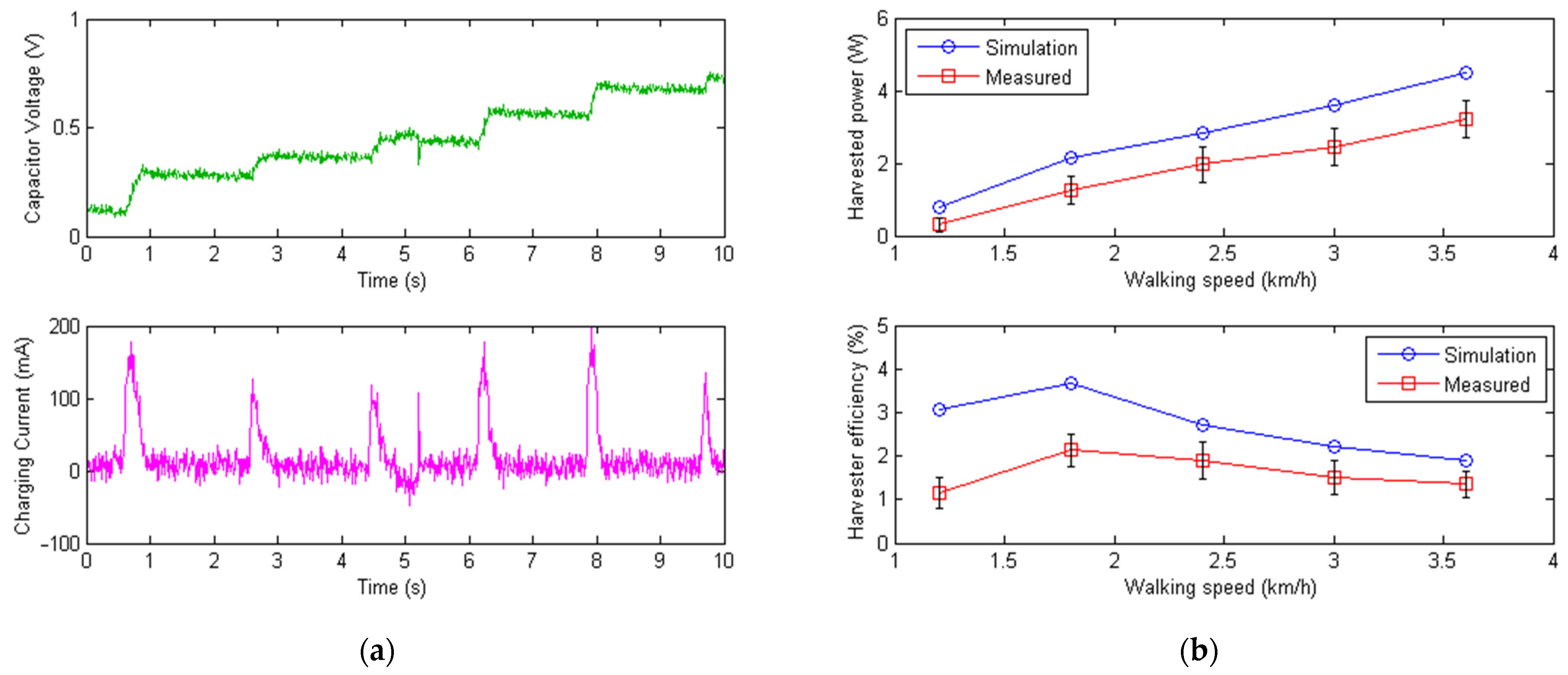
| Walking Speed | Harvested Power Simulated and Measured | Harvester Efficiency Simulated and Measured |
|---|---|---|
| 1.2 km/h | 0.80 W 0.30 W | 3.07% 1.15% |
| 1.8 km/h | 2.15 W 1.25 W | 3.67% 2.13% |
| 2.4 km/h | 2.81 W 1.97 W | 2.71% 1.89% |
| 3.0 km/h | 3.60 W 2.45 W | 2.21% 1.51% |
| 3.6 km/h | 4.48 W 3.23 W | 1.91% 1.38% |
Publisher’s Note: MDPI stays neutral with regard to jurisdictional claims in published maps and institutional affiliations. |
© 2022 by the authors. Licensee MDPI, Basel, Switzerland. This article is an open access article distributed under the terms and conditions of the Creative Commons Attribution (CC BY) license (https://creativecommons.org/licenses/by/4.0/).
Share and Cite
Shi, Y.; Guo, M.; Zhong, H.; Ji, X.; Xia, D.; Luo, X.; Yang, Y. Kinetic Walking Energy Harvester Design for a Wearable Bowden Cable-Actuated Exoskeleton Robot. Micromachines 2022, 13, 571. https://doi.org/10.3390/mi13040571
Shi Y, Guo M, Zhong H, Ji X, Xia D, Luo X, Yang Y. Kinetic Walking Energy Harvester Design for a Wearable Bowden Cable-Actuated Exoskeleton Robot. Micromachines. 2022; 13(4):571. https://doi.org/10.3390/mi13040571
Chicago/Turabian StyleShi, Yunde, Mingqiu Guo, Heran Zhong, Xiaoqiang Ji, Dan Xia, Xiang Luo, and Yuan Yang. 2022. "Kinetic Walking Energy Harvester Design for a Wearable Bowden Cable-Actuated Exoskeleton Robot" Micromachines 13, no. 4: 571. https://doi.org/10.3390/mi13040571
APA StyleShi, Y., Guo, M., Zhong, H., Ji, X., Xia, D., Luo, X., & Yang, Y. (2022). Kinetic Walking Energy Harvester Design for a Wearable Bowden Cable-Actuated Exoskeleton Robot. Micromachines, 13(4), 571. https://doi.org/10.3390/mi13040571