Temperature Characteristics of a Contour Mode MEMS AlN Piezoelectric Ring Resonator on SOI Substrate

Abstract
1. Introduction
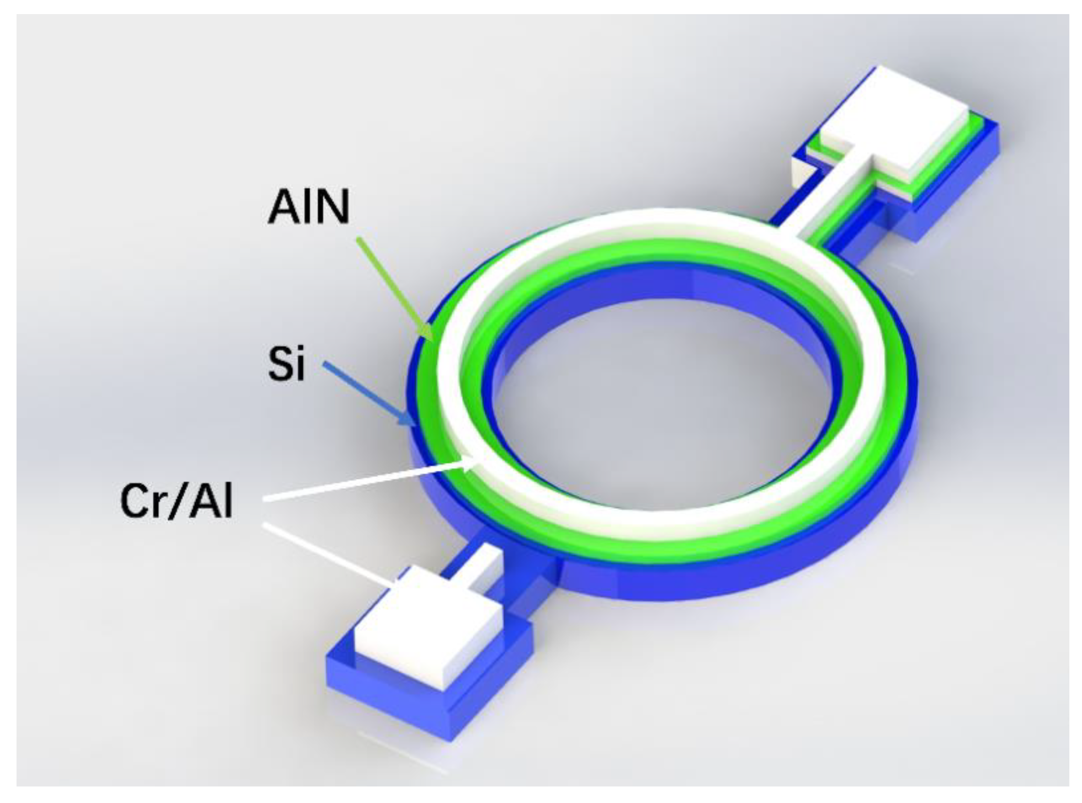
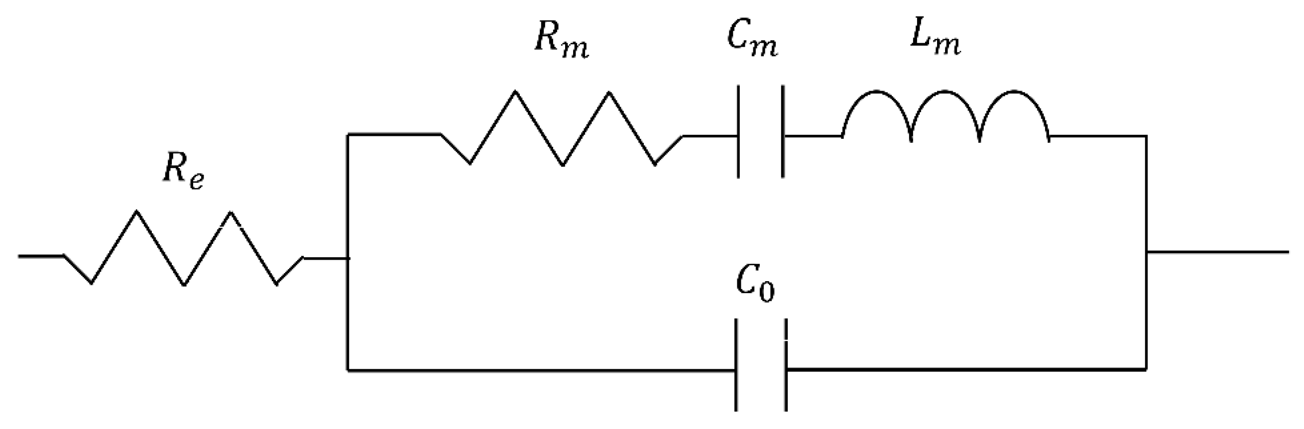
2. Device Design and Modelling
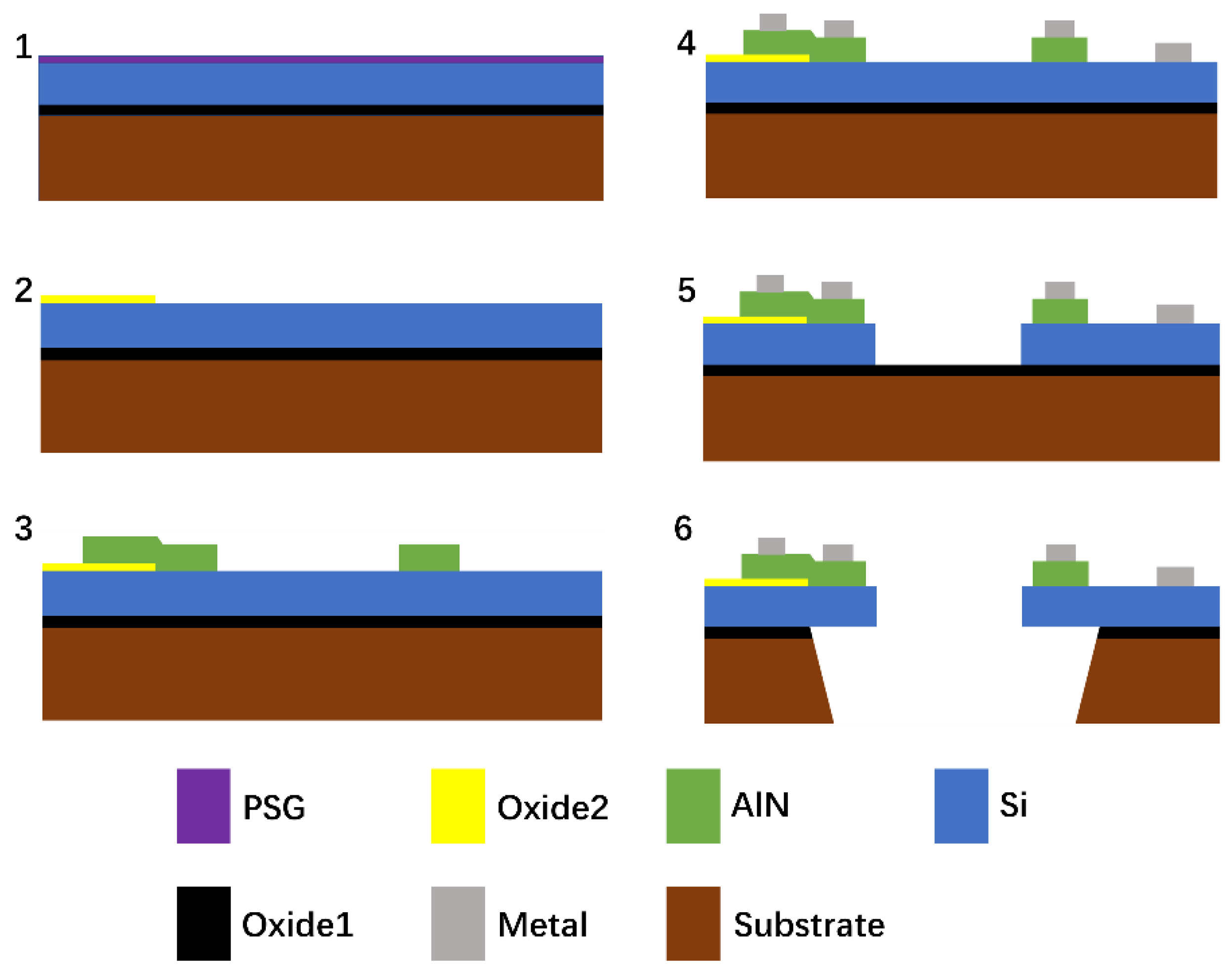
3. Fabrication
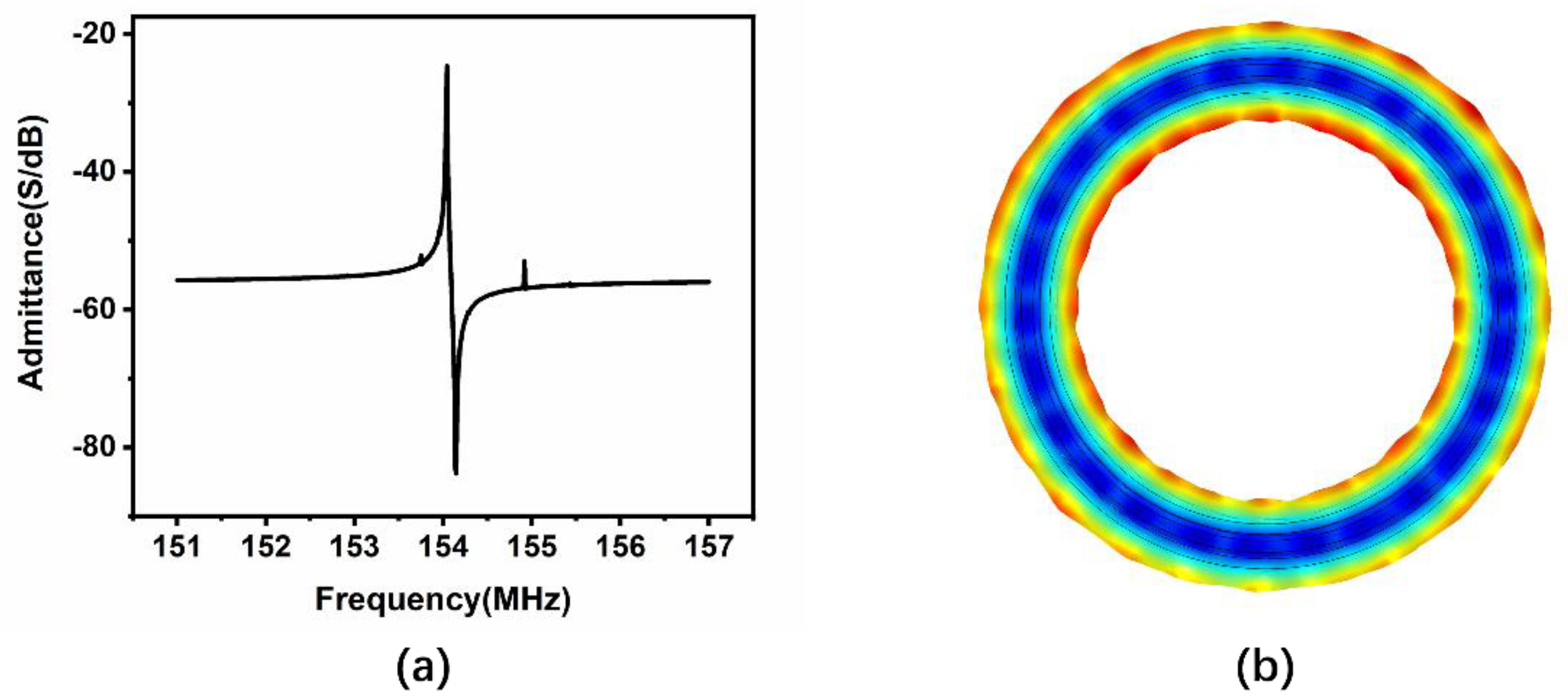
4. Results
5. Conclusions
Author Contributions
Funding
Conflicts of Interest
References
- Yazdi, N.; Ayazi, F.; Najafi, K. Micromachined inertial sensors. Proc. IEEE 1998, 86, 1640–1659. [Google Scholar] [CrossRef]
- Chae, J.; Kulah, H.; Najafi, K. A monolithic three-axis micro-g micromachined silicon capacitive accelerometer. J. Microelectromech. Syst. 2005, 14, 235–242. [Google Scholar] [CrossRef]
- Hu, F.; Yao, J.; Qiu, C.; Ren, H. A MEMS micromirror driven by electrostatic force. J. Electrost. 2010, 68, 237–242. [Google Scholar] [CrossRef]
- Ren, H.; Tao, F.; Wang, W.; Yao, J. An out-of-plane electrostatic actuator based on the lever principle. J. Micromech. Microeng. 2011, 21, 045019. [Google Scholar] [CrossRef]
- Liu, L.; Choi, S. A self-Charging Cyanobacterial Supercapacitor. Biosens. Bioelectron. 2019, 140, 11354. [Google Scholar] [CrossRef]
- Ren, H.; Rangaswami, S.; Lee, H.S.; Chae, J. Enhanced current and power density of micro-scale microbial fuel cells with ultramicroelectrode anodes. J. Micromech. Microeng. 2016, 26, 09501. [Google Scholar]
- Ren, H.; Torres, C.I.; Parameswaran, P.; Rittmann, B.E.; Chae, J. Improved current and power density with a micro-scale microbial fuel cell due to a small characteristic length. Biosens. Bioelectron. 2014, 61, 587–592. [Google Scholar] [CrossRef]
- Wang, R.; Wang, W.; Ren, H.; Chae, J. Detection of copper ions in drinking water using the competitive absorption of proteins. Biosens. Bioelectron. 2014, 57, 179–185. [Google Scholar] [CrossRef]
- Lam, C.S. A review of the recent development of MEMS and crystal oscillators and their impacts on the frequency control products industry. In Proceedings of the 2008 IEEE Ultrasonics Symposium, Beijing, China, 2–5 November 2008; pp. 694–704. [Google Scholar]
- Partridge, A. A new paradigm in time: Silicon MEMS resonators vs. quartz crystals. RD Mag. 2006, 48, 18–21. [Google Scholar]
- Wu, G.; Xu, J.; Zhang, X.; Wang, N.; Yan, D.; Lim, J.L.K.; Zhu, Y.; Li, W.; Gu, Y. Wafer-Level Vacuum-Packaged High-Performance AlN-on-SOI Piezoelectric Resonator for Sub-100-MHz Oscillator Applications. IEEE Trans. Ind. Electron. 2017, 65, 3576–3584. [Google Scholar] [CrossRef]
- Ossama, M.; Pierre, B.; Aurelian, C.; Matthieu, C.; Orlianges, J.C. A zinc dioxide-on-silicon MEMS resonator for narrowband filtering. In Proceedings of the 2014 21st IEEE International Conference on Electronics, Circuits and Systems (ICECS), Marseille, France, 7–10 December 2014; pp. 586–589. [Google Scholar]
- Vishniakou, S.; Chen, R.; Ro, Y.G.; Brennan, C.J.; Levy, C.; Yu, E.T.; Dayeh, S.A. Improved performance of zinc oxide thin film transistor pressure sensors and a demonstration of a commercial chip compatibility with the new force sensing technology. Adv. Mater. Technol. 2018, 3, 170027. [Google Scholar] [CrossRef]
- Isobe, A.; Asai, K. Contour-mode AlN resonator with high coupling factor. Jpn. J. Appl. Phys. 2010, 49, 07HD09. [Google Scholar] [CrossRef]
- Liu, Y.; Cai, Y.; Zhang, Y.; Tovstopyat, A.; Liu, S.; Sun, C. Materials, Design, and Characteristics of Bulk Acoustic Wave Resonator: A Review. Micromachines 2020, 11, 630. [Google Scholar] [CrossRef] [PubMed]
- Wang, G.; Xu, L.X.; Ababneh, A.; Schwarz, P.; Feili, D.; Seidel, H. AlN micromechanical radial-contour disc resonator. J. Micromech. Microeng. 2013, 23, 095002. [Google Scholar] [CrossRef]
- Cleland, A.N.; Pophristic, M.; Ferguson, I. Single-crystal aluminum nitride nanomechanical resonators. Appl. Phys. Lett. 2001, 79, 2070–2072. [Google Scholar] [CrossRef]
- Chen, D.; Ren, W.; Song, S.; Wang, J.; Liu, W.; Wang, P. The high Q factor lateral field–excited thickness shear mode film bulk acoustic resonator working in liquid. Micromachines 2016, 7, 231. [Google Scholar] [CrossRef]
- Jung, S.I.; Ryu, C.; Piazza, G.; Kim, H.J. A study on the effects of bottom electrode designs on aluminum nitride contour-mode resonators. Micromachines 2019, 10, 758. [Google Scholar]
- Zou, J.; Lin, C.M.; Gao, A.; Pisano, A.P. The Multi-Mode Resonance in AlN Lamb Wave Resonators. J. Microelectromech. Syst. 2018, 27, 973–984. [Google Scholar] [CrossRef]
- Piazza, G.; Stephanou, P.J.; Pisano, A.P. Single-Chip Multiple-Frequency AlN MEMS Filters Based on Contour-Mode Piezoelectric Resonators. J. Microelectromech. Syst. 2007, 16, 319–328. [Google Scholar] [CrossRef]
- Dubois, M.A.; Muralt, P. Properties of aluminum nitride thin films for piezoelectric transducers and microwave filter applications. Appl. Phys. Lett. 1999, 74, 3032–3034. [Google Scholar] [CrossRef]
- Bjurström, J.; Wingqvist, G.; Yantchev, V.; Katardjiev, I. Temperature compensation of liquid FBAR sensors. J. Micromech. Microeng. 2007, 17, 651–658. [Google Scholar] [CrossRef]
- Lakin, K.M.; Belsick, J.; McDonald, J.F.; McCarron, K.T. Improved bulk wave resonator coupling coefficient for wide bandwidth filters. In Proceedings of the 2001 IEEE Ultrasonics Symposium. Proceedings. An. International Symposium (Cat. No. 01CH37263), Atlanta, GA, USA, 7–10 October 2001; Volume 1, pp. 827–831. [Google Scholar]
- Lin, C.M.; Yen, T.T.; Lai, Y.J.; Felmetsger, V.V.; Hopcroft, M.A.; Kuypers, J.H.; Pisano, A.P. Temperature-Compensated Aluminum Nitride Lamb Wave Resonator. IEEE Trans. Ultrason. Ferroelectr. Freq. Control 2010, 57, 524–532. [Google Scholar] [PubMed]
- Wang, Z.; Zhu, H.; Dong, Y.; Feng, G. A Thickness-Shear Quartz Resonator Force Sensor with Dual-Mode Temperature Compensation. IEEE Sens. J. 2003, 3, 490–496. [Google Scholar] [CrossRef]
- Islam, M.S.; Wei, R.; Lee, J.; Xie, Y.; Mandal, S.; Feng, P.X.L. A Temperature-Compensated Single-Crystal Silicon-on-Insulator (SOI) MEMS Oscillator with a CMOS Amplifier Chip. Micromachines 2018, 9, 559. [Google Scholar]
- Salvia, J.; Melamud, R.; Chandorkar, S.; Lee, H.K.; Qu, Y.Q.; Lord, S.F.; Murmann, B.; Kenny, T.W. Phase lock loop based temperature compensation for MEMS oscillators. In Proceedings of the 2009 IEEE 22nd International Conference on Micro Electro Mechanical Systems, Sorrento, Italy, 25–29 January 2009; pp. 661–664. [Google Scholar]
- Kwon, H.K.; Ortiz, L.C.; Vukasin, G.D.; Chen, Y.; Shin, D.D.; Kenny, T.W. An Oven-Controlled MEMS Oscillator (OCMO) With Sub 10mw, ±1.5 PPB Stability Over Temperature. In Proceedings of the 2019 20th International Conference on Solid-State Sensors, Actuators and Microsystems & Eurosensors XXXIII (TRANSDUCERS & EUROSENSORS XXXIII), Berlin, Germany, 23–27 June 2019; pp. 2072–2075. [Google Scholar]
- Wingqvist, G.; Arapan, L.; Yantchev, V.; Katardjiev, I. A micromachined thermally compensated thin film Lamb wave resonator for frequency control and sensing applications. J. Micromech. Microeng. 2009, 19, 035018. [Google Scholar] [CrossRef]
- Hsu, W.T.; Clark, J.R.; Nguyen, C.C. Mechanically temperature-compensated flexural-mode micromechanical resonators. In Proceedings of the International Electron Devices Meeting 2000. Technical Digest. IEDM (Cat. No.00CH37138), San Francisco, CA, USA, 10–13 December 2000; pp. 399–402. [Google Scholar]
- Myers, D.R.; Azevedo, R.G.; Chen, L.; Mehregany, M.; Pisano, A.P. Passive substrate temperature compensation of doubly anchored double-ended tuning forks. J. Microelectromech. Syst. 2012, 21, 1321–1328. [Google Scholar]
- Samarao, A.K.; Ayazi, F. Temperature compensation of silicon resonators via degenerate doping. IEEE Trans. Electron. Devices 2011, 59, 87–93. [Google Scholar] [CrossRef]
- Shahraini, S.; Mansoorzare, H.; Mahigir, A.; Abdolvand, R. Thickness-Lamé Thin-Film Piezoelectric-on-Silicon Resonators. J. Microelectromech. Syst. 2020, 29, 296–305. [Google Scholar] [CrossRef]
- Ng, E.J.; Hong, V.A.; Yang, Y.; Ahn, C.H.; Everhart, C.L.; Kenny, T.W. Temperature dependence of the elastic constants of doped silicon. J. Microelectromech. Syst. 2014, 24, 730–741. [Google Scholar] [CrossRef]
- Fei, S.; Ren, H. A Contour Mode AIN Piezoelectric Resonator based on SOI Substrate. In Proceedings of the 2020 IEEE 15th International Conference on Nano/Micro Engineered and Molecular System (NEMS), San Diego, CA, USA, 27–30 September 2020; pp. 180–183. [Google Scholar]
- Chauhan, S.S.; Joglekar, M.M.; Manhas, S.K. Influence of Process Parameters and Formation of Highly c-Axis Oriented AlN Thin Film on Mo by Reactive Sputtering. J. Electron. Mater. 2018, 47, 7520–7530. [Google Scholar] [CrossRef]
- Larson, J.D.; Bradley, P.D.; Wartenberg, S.; Ruby, R.C. Modified Butterworth-Van Dyke circuit for FBAR resonators and automated measurement system. 2000 Proc. IEEE Ultrason. Symp. 2000, 1, 863–868. [Google Scholar]
- Xu, W.; Appel, J.; Chae, J. Real-time monitoring of whole blood coagulation using a microfabricated contour-mode film bulk acoustic resonator. J. Microelectromech. Syst. 2012, 21, 302–307. [Google Scholar] [CrossRef]
- Piazza, G.; Stephanou, P.J.; Pisano, A.P. Piezoelectric Aluminum Nitride Vibrating Contour-Mode MEMS Resonators. J. Microelectromech. Syst. 2006, 15, 1406–1418. [Google Scholar] [CrossRef]
- Iqbal, A.; Walker, G.; Hold, L.; Fernandes, A.; Lacopi, A.; Mohd-Yasin, F. Sputtering of aluminium nitride (002) film on cubic silicon carbide on silicon (100) substrate: Influences of substrate temperature and deposition power. J. Mater. Sci. Mater. Electron. 2020, 31, 239–248. [Google Scholar] [CrossRef]
- Kim, E.; Choi, Y.K.; Song, J.; Lee, J. Detection of various self-assemble monolayers by AlN-based film bulk acoustic resonator. Mater. Res. Bull. 2013, 48, 5076–5079. [Google Scholar] [CrossRef]
- Tu, C.; Lee, J.Y. Low Temperature Quality Factor Scaling of Laterally-vibrating AlN Piezoelectric-on-silicon Resonators. Procedia Eng. 2015, 120, 7–10. [Google Scholar] [CrossRef][Green Version]
- Wu, G.Q.; Xu, D.H.; Xiong, B.; Wang, Y.L. Effect of air damping on quality factor of bulk mode microresonators. Microelectron. Eng. 2013, 103, 86–91. [Google Scholar] [CrossRef]
- Corman, T.; Enoksson, P.; Norén, K.; Stemme, G. A low-pressure encapsulated resonant fluid density sensor with feedback control electronics. Meas. Sci. Technol. 2000, 11, 205–211. [Google Scholar]
- Kim, B.; Hopcroft, M.A.; Candler, R.N.; Jha, C.M.; Agarwal, M.; Melamud, R.; Chandorkar, S.A.; Yama, G.; Kenny, T.W. Temperature Dependence of Quality Factor in MEMS Resonator. J. Microelectromech. Syst. 2008, 17, 755–766. [Google Scholar] [CrossRef]
- Melamud, R.; Chandorkar, S.A.; Kim, B.; Lee, H.K.; Salvia, J.C.; Bahl, G.; Hopcroft, M.A.; Kenny, T.W. Temperature-insensitive composite micromechanical resonators. J. Microelectromech. Syst. 2009, 18, 1409–1419. [Google Scholar] [CrossRef]


| Parameters | Value in |
|---|---|
| Thickness of top silicon layer | 10 |
| Thickness of AlN layer | 0.5 |
| Width of silicon ring | 30 |
| Width of AlN ring | 16.6 |
| Width of Cr/Al ring | 8 |
| Radius of Si/AlN/Cr/Al ring | 160 |
Publisher’s Note: MDPI stays neutral with regard to jurisdictional claims in published maps and institutional affiliations. |
© 2021 by the authors. Licensee MDPI, Basel, Switzerland. This article is an open access article distributed under the terms and conditions of the Creative Commons Attribution (CC BY) license (http://creativecommons.org/licenses/by/4.0/).
Share and Cite
Fei, S.; Ren, H. Temperature Characteristics of a Contour Mode MEMS AlN Piezoelectric Ring Resonator on SOI Substrate. Micromachines 2021, 12, 143. https://doi.org/10.3390/mi12020143
Fei S, Ren H. Temperature Characteristics of a Contour Mode MEMS AlN Piezoelectric Ring Resonator on SOI Substrate. Micromachines. 2021; 12(2):143. https://doi.org/10.3390/mi12020143
Chicago/Turabian StyleFei, Sitao, and Hao Ren. 2021. "Temperature Characteristics of a Contour Mode MEMS AlN Piezoelectric Ring Resonator on SOI Substrate" Micromachines 12, no. 2: 143. https://doi.org/10.3390/mi12020143
APA StyleFei, S., & Ren, H. (2021). Temperature Characteristics of a Contour Mode MEMS AlN Piezoelectric Ring Resonator on SOI Substrate. Micromachines, 12(2), 143. https://doi.org/10.3390/mi12020143