A Hybrid Numerical Methodology Based on CFD and Porous Medium for Thermal Performance Evaluation of Gas to Gas Micro Heat Exchanger


 ,
, 
Abstract
1. Introduction
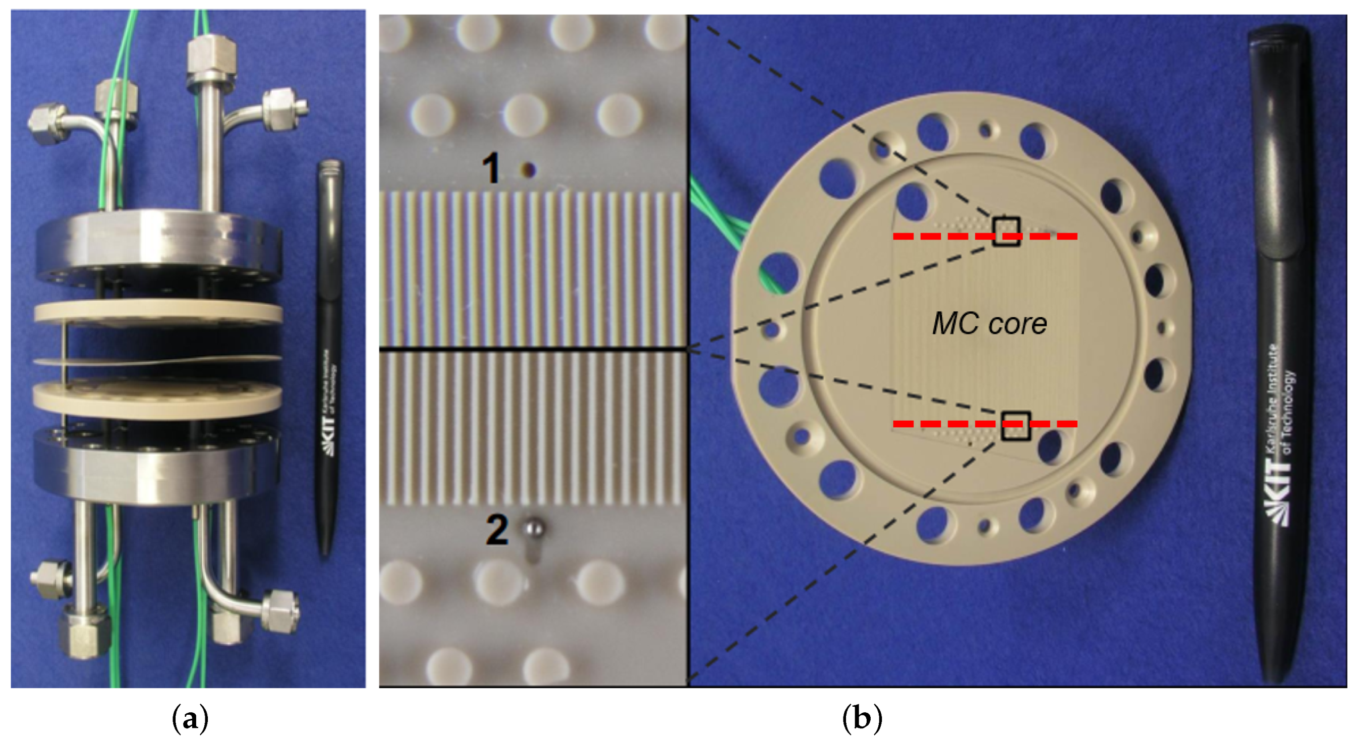
2. Background
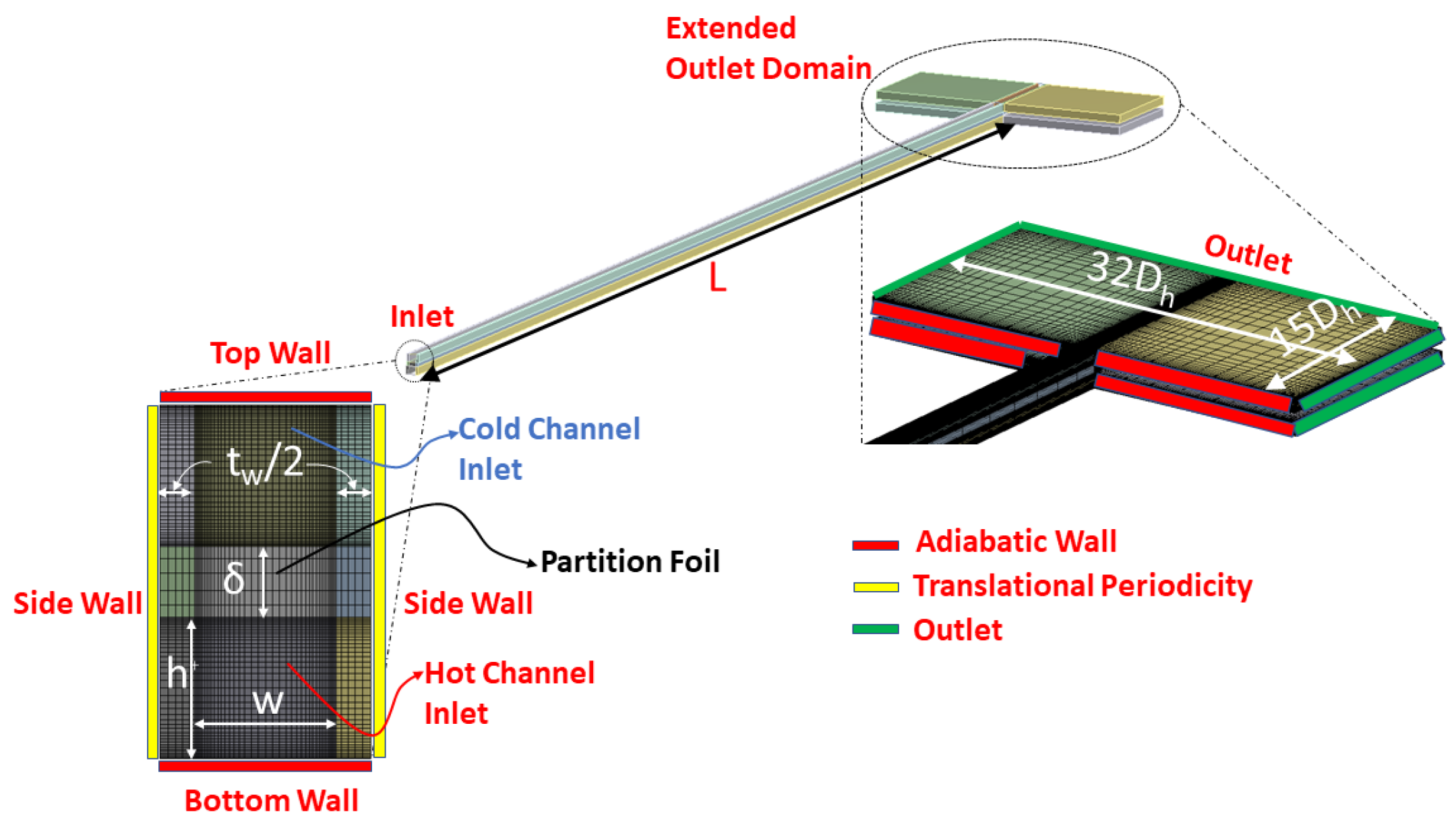
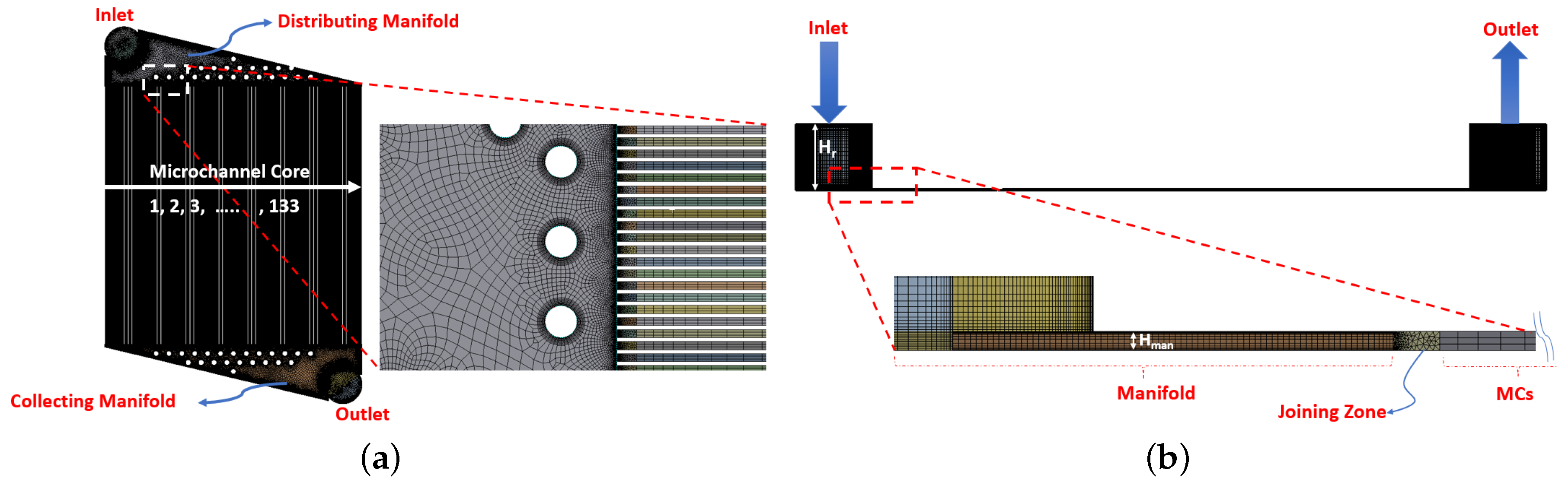
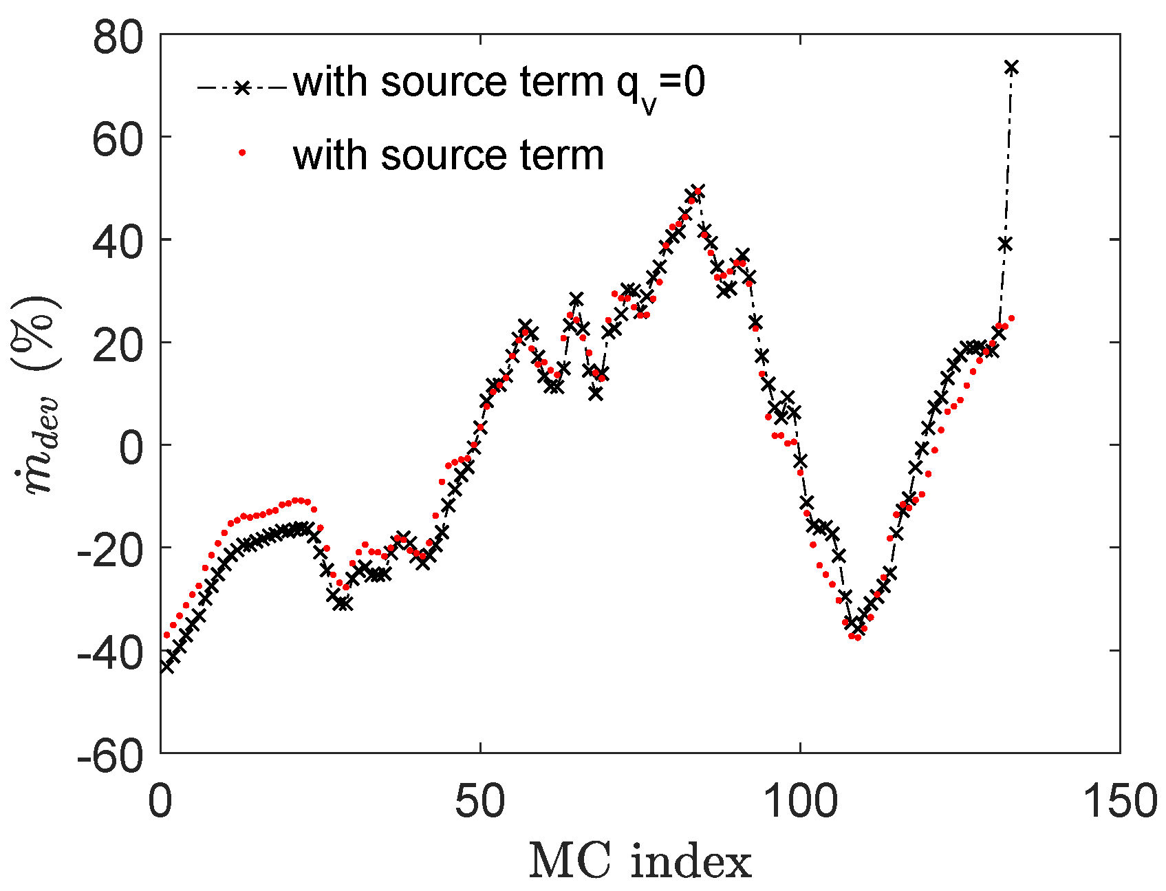
3. Numerical Methodology
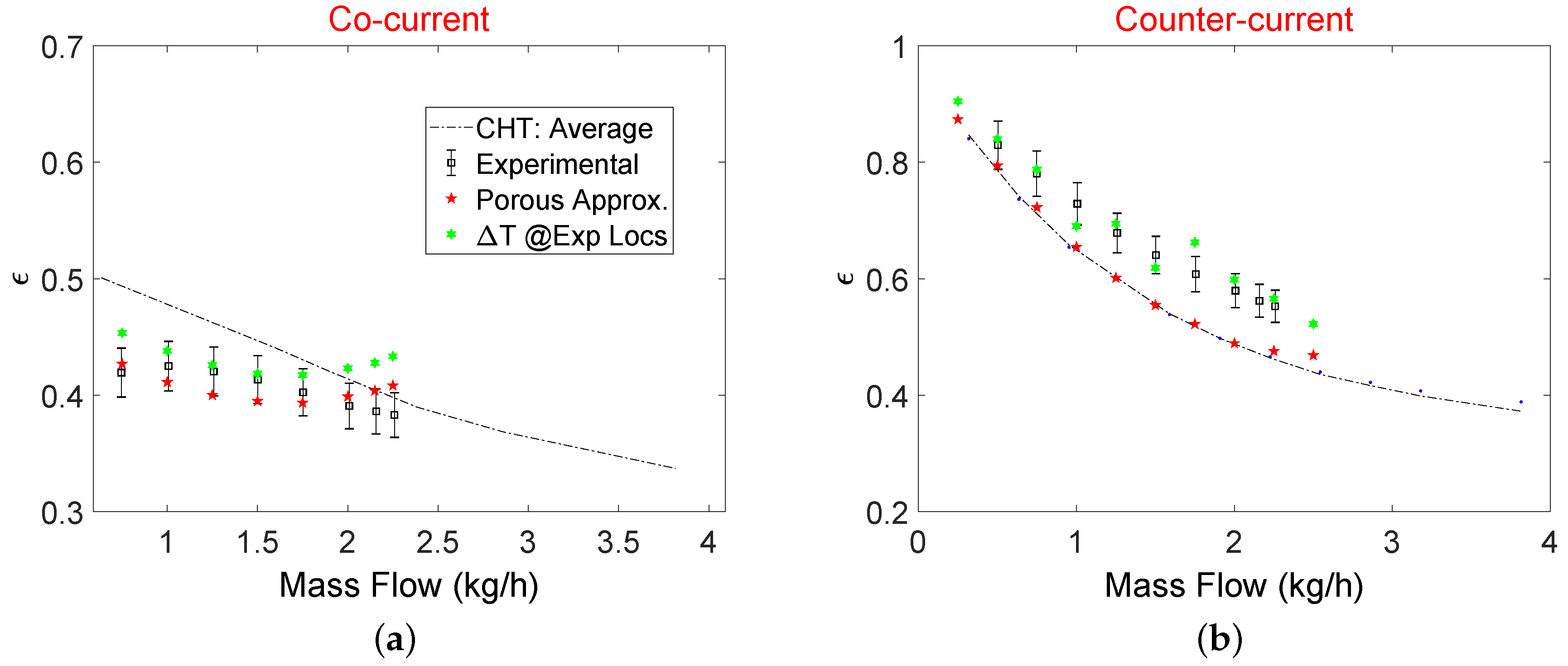
4. Results
4.1. CHT Model
4.2. Porous Model
5. Conclusions
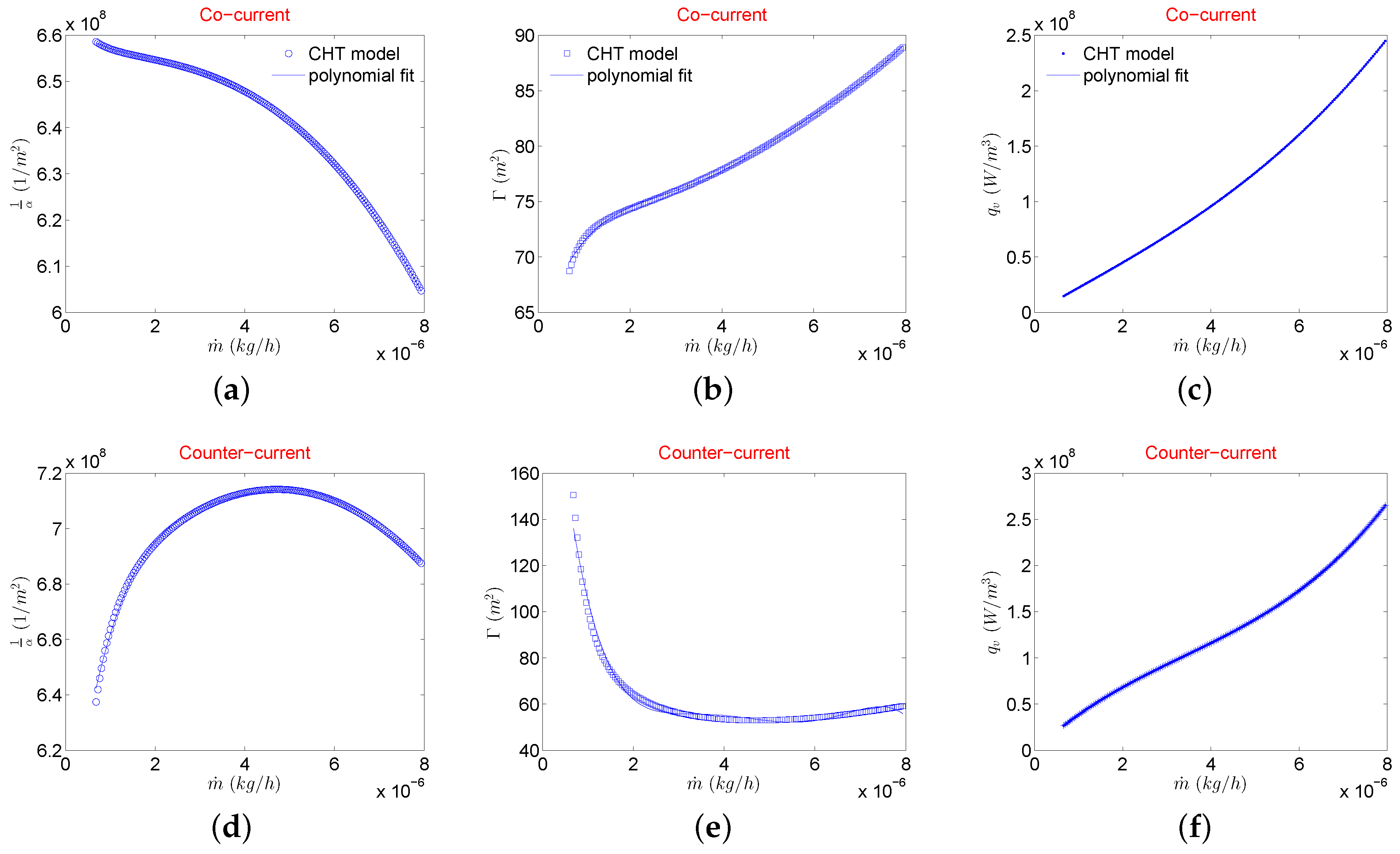
- Porous medium coefficients for parallel channel Hx can be extracted for compressible fluids by modifying the existing Darcy–Forchheimer law to incorporate for the strong density variations with increasing mass flow rates in MCs.
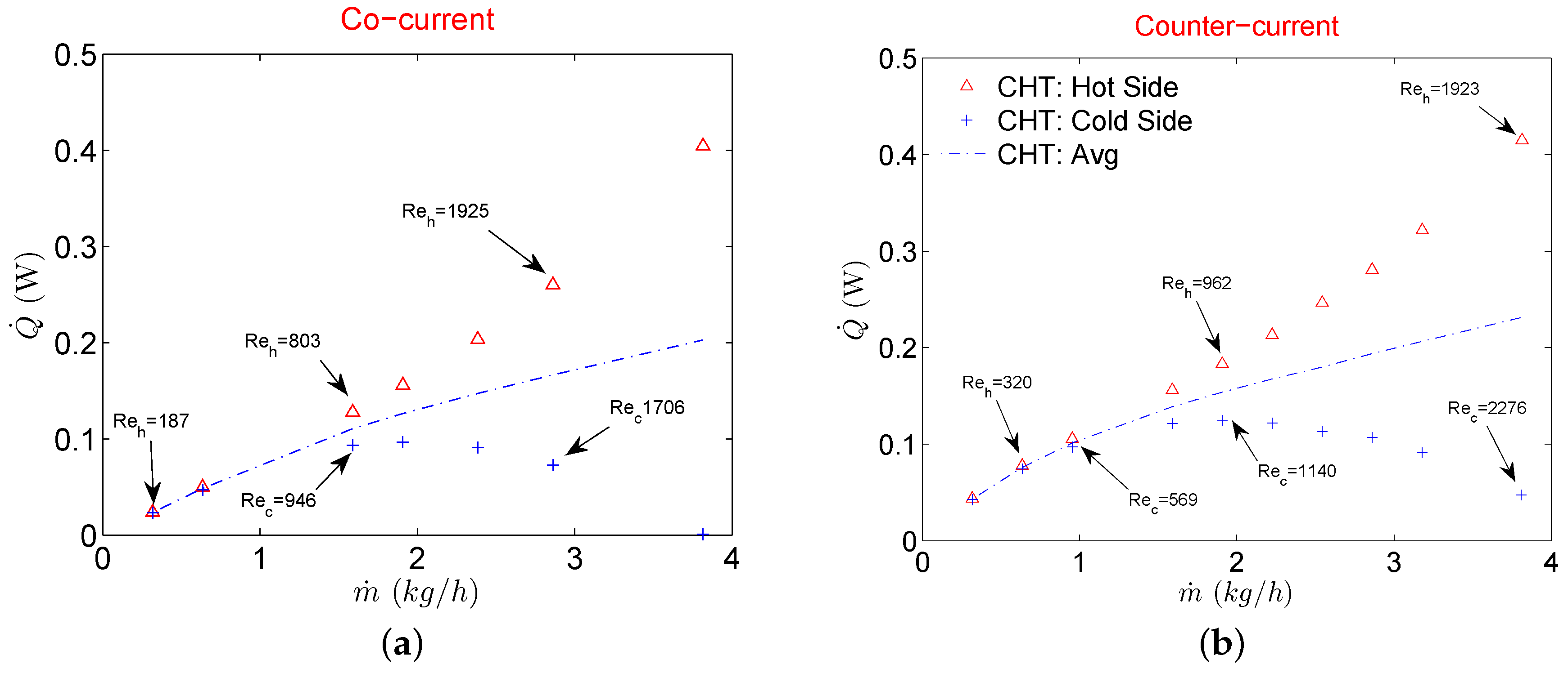
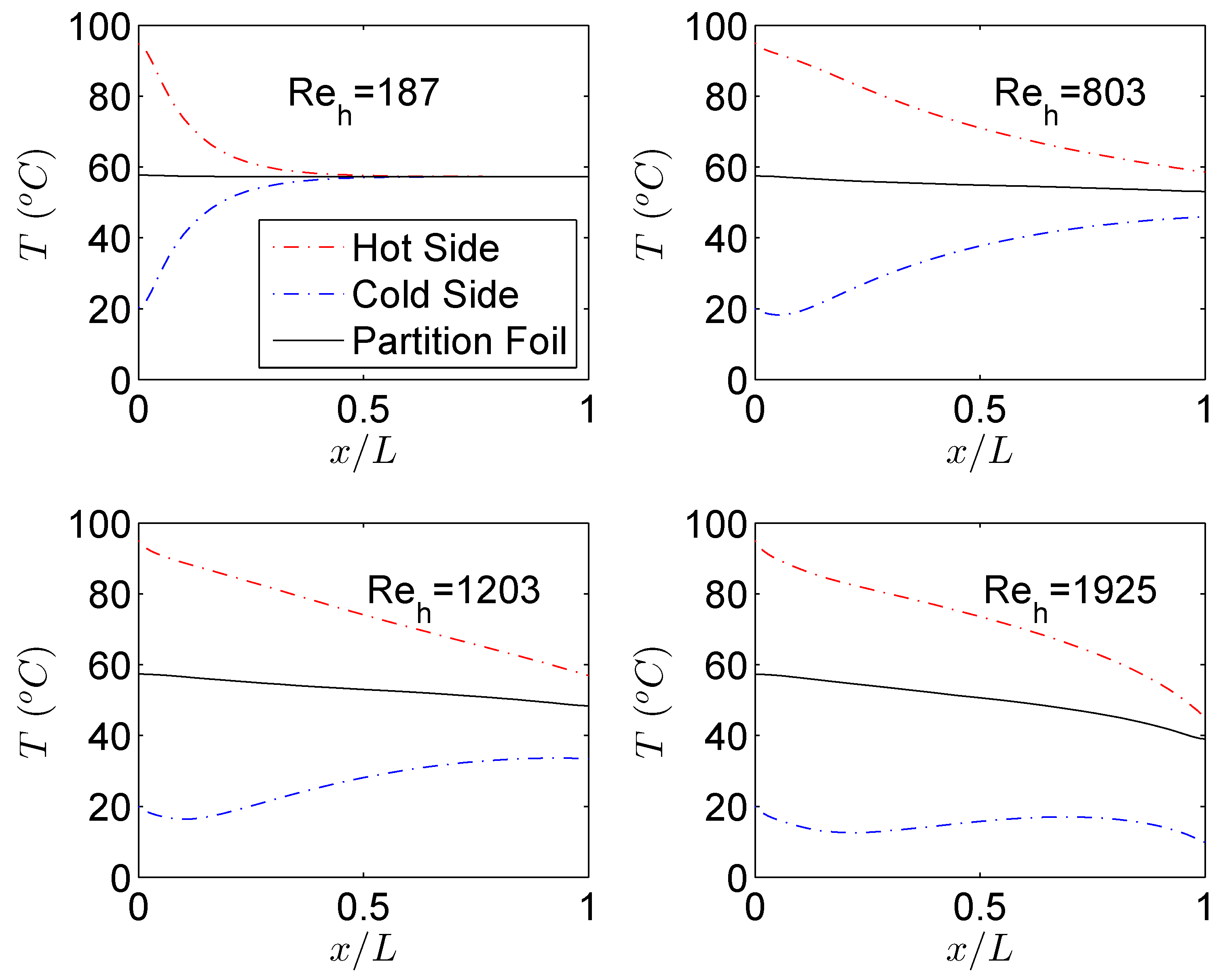
- CHT analysis revealed that gas in both hot and cold fluid streams experiences a “self-cooling” phenomenon where the temperature of the gases keeps on decreasing from inlet to the outlet at higher mass flow rates (). Therefore for a Hx operating under balanced mass flow rates, smaller values of mass flow rates are recommended.
- Pressure drop of the porous model is much higher compared to the CHT due to the presence of collecting and dividing manifolds. Pressure drop estimation using the porous model is in good agreement with the experimental results of the same Hx.
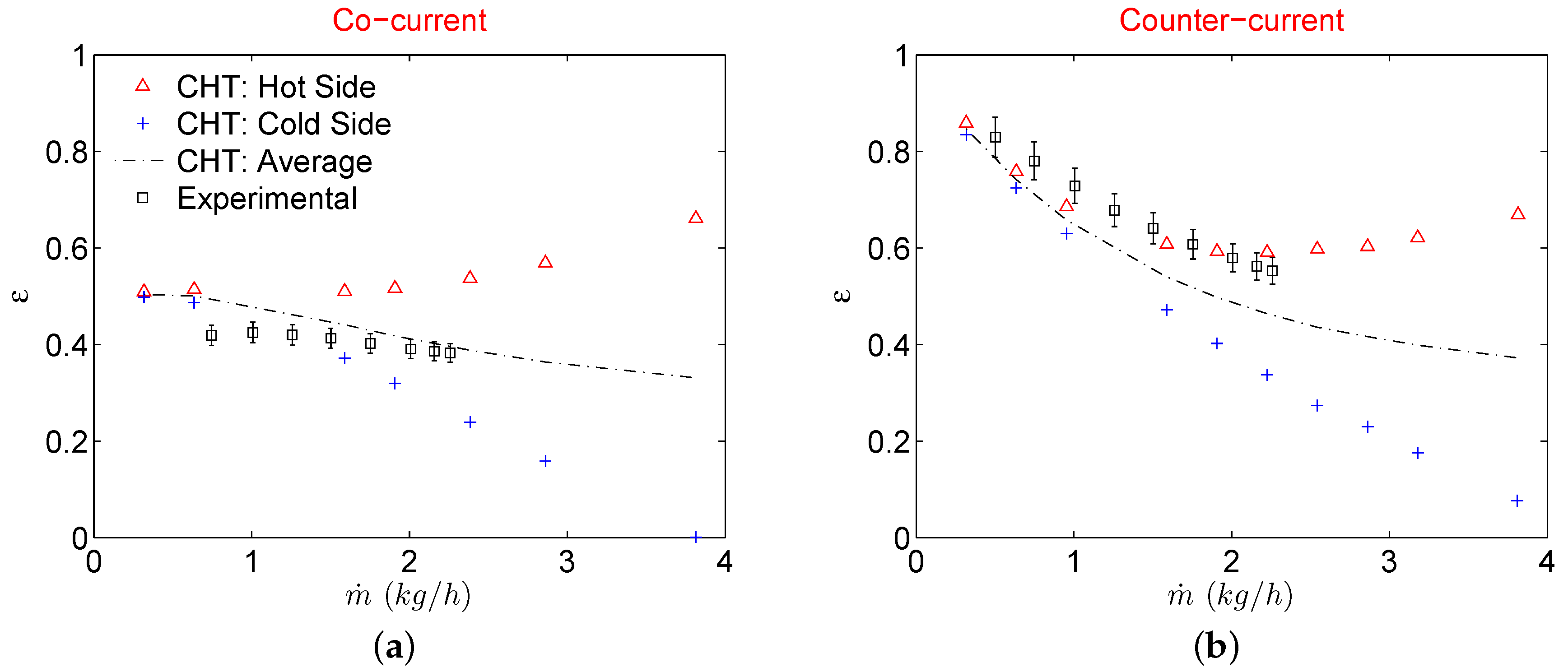
- Overall heat exchanger effectiveness of a Hx in a counterflow configuration is identical to that of the CHT analysis on the range of mass flows investigated in this study. For a cocurrent configuration, however, heat exchanger effectiveness from porous model matches well with experimental results while the CHT model overpredicts it.
- Compared to the meshing strategy adopted in CHT analysis, the porous model results in saving of at least 20 million computational nodes for the double layer gas to gas Hx investigated in this study with good enough predictions of global pressure drop and heat exchanger effectiveness.
Author Contributions
Funding
Conflicts of Interest
References
- Kim, S.J.; Kim, D. Forced Convection in Microstructures for Electronic Equipment Cooling. ASME J. Heat Transf. 1999, 121, 639–645. [Google Scholar] [CrossRef]
- Kim, S.J.; Kim, D.; Lee, D.Y. On the Local Thermal Equilibrium in Microchannel Heat Sinks. Int. J. Heat Mass Transf. 2000, 43, 1735–1748. [Google Scholar] [CrossRef]
- Tuckerman, D.; Pease, R. High-performance heat sinking for VLSI. IEEE Electron Device Lett. 1981, 5, 126–129. [Google Scholar] [CrossRef]
- Knight, R.; Goodling, J.; Hall, D. Optimal Thermal Design of Forced Convection Heat Sinks-Analytical. ASME J. Electron. Packag. 1991, 113, 313–321. [Google Scholar] [CrossRef]
- Dong, L.; Garimella, S. Analysis and Optimization of the Termal Performance of Microchannel Heat Sinks. Int. J. Numer. Heat Fluid Flow 2005, 15, 7–26. [Google Scholar]
- Lim, F.Y.; Abdullah, S.; Ahmad, I. Numerical Study of Fluid Flow and Heat Transfer in MicroChannel Heat Sinks using Anisotropic Porous Media Approximation. J. Appl. Sci. 2010, 10, 2047–2057. [Google Scholar] [CrossRef]
- Alm, B.; Imke, U.; Knitter, R.; Schygulla, U.; Zimmermann, S. Testing and simulation of ceramic micro heat exchangers. Chem. Eng. J. 2008, 135, S179–S184. [Google Scholar] [CrossRef]
- Joseph, J.; Nacereddine, R.; Delanaye, M.; Giraldo, A.; Roubah, M.; Brandner, J. Advanced CFD methodology to investigate heat exchanger performance and experimental validation of a reduced model for a micro-CHP application. In Proceedings of the 6th Micro and Nano Flows Conference (MNF2018), Atlanta, GA, USA, 6–7 September 2018. [Google Scholar]
- Joseph, J.; Nacereddine, R.; Delanaye, M.; Korvink, J.G.; Brandner, J.J. Advanced Numerical Methodology to Analyze High-Temperature Wire-Net Compact Heat Exchangers For a Micro-Combined Heat and Power System Application. Heat Transf. Eng. 2019, 41, 1–13. [Google Scholar] [CrossRef]
- Joseph, J.; Delanaye, M.; Nacereddine, R.; Giraldo, A.; Rouabah, M.; Korvink, J.G.; Brandner, J.J. Numerical Study of Perturbators Influence on Heat Transfer and Investigation of Collector Performance for a Micro-Combined Heat and Power System Application. Heat Transf. Eng. 2020, 42, 1–23. [Google Scholar] [CrossRef]
- Rehman, D.; Joseph, J.; Morini, G.; Delanaye, M.; Brandner, J. A Porous Media Model for a Double Layered Gas-to-Gas Micro Heat Exchanger operating in Laminar Flow Regime. In Proceedings of the 37th UIT Heat Transfer Conference, Padova, Italy, 24–26 June 2019. [Google Scholar]
- Yang, Y.; Morini, G.L.; Brandner, J.J. Experimental analysis of the influence of wall axial conduction on gas-to-gas micro heat exchanger effectiveness. Int. J. Heat Mass Transf. 2014, 69, 17–25. [Google Scholar] [CrossRef]
- Yang, Y.; Gerken, I.; Brandner, J.J.; Morini, G.L. Design and Experimental Investigation of a Gas-to-Gas Counter-Flow Micro Heat Exchanger. Exp. Heat Transf. 2014, 27, 340–359. [Google Scholar] [CrossRef]
- Gerken, I.; Brandner, J.J.; Dittmeyer, R. Heat transfer enhancement with gas-to-gas micro heat exchangers. Appl. Therm. Eng. 2016, 93, 1410–1416. [Google Scholar] [CrossRef]
- Yang, Y. Experimental and Numerical Analysis of Gas Forced Convection through Microtubes and Micro Heat Exchangers. Ph.D. Thesis, Universita di Bologna, Bologna, Italy, 2012. [Google Scholar]
- Abraham, J.; Sparrow, E.; Tong, J. Breakdown of laminar pipe flow into transitional intermittency and subsequent attainment of fully developed intermittent or turbulent flow. Numer. Heat Transf. Part B Fundam. 2008, 54, 103–115. [Google Scholar] [CrossRef]
- Abraham, J.; Sparrow, E.; Minkowycz, W. Internal-flow Nusselt numbers for the low-Reynolds-number end of the laminar-to-turbulent transition regime. Int. J. Heat Mass Transf. 2011, 54, 584–588. [Google Scholar] [CrossRef]
- Minkowycz, W.; Abraham, J.; Sparrow, E. Numerical simulation of laminar breakdown and subsequent intermittent and turbulent flow in parallel-plate channels: Effects of inlet velocity profile and turbulence intensity. Int. J. Heat Mass Transf. 2009, 52, 4040–4046. [Google Scholar] [CrossRef]
- Koyama, K.; Asako, Y. Experimental Investigation of Heat Transfer Characteristics on a Gas-to-Gas Parallel Flow Microchannel Heat Exchanger. Open Transp. Phenom. J. 2010, 2, 1–8. [Google Scholar] [CrossRef]
- Koyama, K.; Asako, Y. Experimental Investigation of Heat Transfer Characteristics on a Gas-to-Gas Counterflow Microchannel Heat Exchanger. Exp. Heat Transf. 2010, 23, 130–143. [Google Scholar] [CrossRef]
- Rehman, D.; Morini, G.L.; Hong, C. A Comparison of Data Reduction Methods for Average Friction Factor Calculation of Adiabatic Gas Flows in Microchannels. Micromachines 2019, 10, 171. [Google Scholar] [CrossRef] [PubMed]
- Hong, C.; Tanaka, G.; Asako, Y.; Katanoda, H. Flow characteristics of gaseous flow through a microtube discharged into the atmosphere. Int. J. Heat Mass Transf. 2018, 121, 187–195. [Google Scholar] [CrossRef]
- Renault, C.; Colin, S.; Orieux, S.; Cognet, P.; Tzédakis, T. Optimal design of multi-channel microreactor for uniform residence time distribution. Microsyst. Technol. 2012, 18, 209–223. [Google Scholar] [CrossRef][Green Version]


| Parameter | Symbol (Units) | Value |
|---|---|---|
| MC width | m) | 200 |
| MC height | m) | 200 |
| MC Length | m) | 40 |
| Hydraulic Diameter | m) | 200 |
| Wall Thickness | m) | 100 |
| MC housing (PMMA) conductivity | (W/m/K) | |
| Partition Foil (Stainless Steel) thickness | m) | 100 |
| Partition Foil conductivity | (W/m/K) | 15 |
| Boundary | Value | |
|---|---|---|
| Hot Side | Cold Side | |
| Inlet | evaluated using Equation (10) for cold side | |
| C | C | |
| Side Walls | Translational Periodicity | |
| Top & Bottom Walls | Adiabatic | |
| Outlet | Pressure outlet, p = | |
| Boundary | Value |
|---|---|
| Inlet | from experimental testing |
| = 90 C | |
| MCs walls | Free slip |
| Inertial and visocus coefficients | Determined from CHT analysis |
| Energy source term | Determined from CHT analysis |
| Manifolds walls | Adiabatic/ No slip |
| Outlet | Pressure outlet, p = |
© 2020 by the authors. Licensee MDPI, Basel, Switzerland. This article is an open access article distributed under the terms and conditions of the Creative Commons Attribution (CC BY) license (http://creativecommons.org/licenses/by/4.0/).
Share and Cite
Rehman, D.; Joseph, J.; Morini, G.L.; Delanaye, M.; Brandner, J. A Hybrid Numerical Methodology Based on CFD and Porous Medium for Thermal Performance Evaluation of Gas to Gas Micro Heat Exchanger. Micromachines 2020, 11, 218. https://doi.org/10.3390/mi11020218
Rehman D, Joseph J, Morini GL, Delanaye M, Brandner J. A Hybrid Numerical Methodology Based on CFD and Porous Medium for Thermal Performance Evaluation of Gas to Gas Micro Heat Exchanger. Micromachines. 2020; 11(2):218. https://doi.org/10.3390/mi11020218
Chicago/Turabian StyleRehman, Danish, Jojomon Joseph, Gian Luca Morini, Michel Delanaye, and Juergen Brandner. 2020. "A Hybrid Numerical Methodology Based on CFD and Porous Medium for Thermal Performance Evaluation of Gas to Gas Micro Heat Exchanger" Micromachines 11, no. 2: 218. https://doi.org/10.3390/mi11020218
APA StyleRehman, D., Joseph, J., Morini, G. L., Delanaye, M., & Brandner, J. (2020). A Hybrid Numerical Methodology Based on CFD and Porous Medium for Thermal Performance Evaluation of Gas to Gas Micro Heat Exchanger. Micromachines, 11(2), 218. https://doi.org/10.3390/mi11020218