Article

Spectral-Spatial Clustering with a Local Weight Parameter Determination Method for Remote Sensing Imagery

The State Key Laboratory of Information Engineering in Surveying, Mapping and Remote Sensing, Wuhan University, Wuhan 430079, China
*
Author to whom correspondence should be addressed.
Remote Sens. 2016, 8(2), 124; https://doi.org/10.3390/rs8020124
Submission received: 27 September 2015 / Revised: 13 January 2016 / Accepted: 1 February 2016 / Published: 5 February 2016

Abstract

:
Remote sensing image clustering is a challenging task considering its intrinsic complexity. Recently, by combining the spectral and spatial information of the remote sensing data, the clustering performance can be dramatically enhanced, termed as Spectral-Spatial Clustering (SSC). However, it has always been difficult to determine the weight parameter for balancing the spectral term and spatial term of the clustering objective function. In this paper, spectral-spatial clustering with a local weight parameter determination method for remote sensing image was proposed, i.e., L-SSC. In L-SSC, considering the large scale of remote sensing images, the weight parameter can be determined locally in a patch image instead of the whole image. Afterwards, the local weight parameter was used in constructing the objective function of L-SSC. Thus, the remote sensing image clustering problem was transformed into an optimization problem. Finally, in order to achieve a better optimization performance, a variant of differential evolution (i.e., jDE) was used as the optimizer due to its powerful optimization capability. Experimental results on three remote sensing images, including a Wuhan TM image, a Fancun Quickbird image, and an Indian Pine AVIRIS image, demonstrated that the proposed L-SSC can acquire higher clustering accuracy in comparison to other spectral-spatial clustering methods.

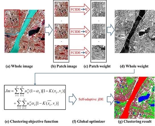
Graphical Abstract

1. Introduction

Clustering is one of the most important techniques in remote sensing image processing. The aim of remote sensing clustering is to partition a given image into groups such that pixels in the same group are as similar to each other as possible while those assigned to different groups are dissimilar [1,2]. With the development of satellite sensors, the spatial resolution of remote sensing images increases, resulting in the fact that pixels of the same land use/cover class may not have a similar spectral property [3,4]. Thus, isolated pixels, namely “salt and pepper” effects, may emerge in remote sensing image clustering results. Furthermore, due to the existence of noise and outliers, these effects are aggravated.
Fortunately, the spatial information embedded in a remote sensing image can take the homogeneity of neighbor pixels into consideration [5], which has been used in remote sensing image processing, such as classification [6], semi-supervised classification [7], segmentation [8], and hyperspectral unmixing [9]. Especially, coupled with spectral information, the spatial information can also be utilized in remote sensing image clustering, termed as Spectral-Spatial Clustering (i.e., SSC). Firstly, the spatial features (i.e., GLCM, Morphological Profile) can be extracted and stacked with the spectral feature [10]. An accurate spatial feature extraction method can be effective in SSC. However, the selection of the appropriate spatial feature is not an easy task because of different class distributions with regard to different regions. Secondly, object-based techniques can be used for introducing the spatial information in SSC, which can be implemented by combining the traditional pixel-wise unsupervised classification method with segmentation [11].
Both the spatial feature stacking technique and the object-based technique can be thought of as pre- and post-processing techniques, which can be easily combined with other spectral-spatial clustering methods. Among these methods, the FCM-based spectral-spatial clustering method is our focus because of its easy implementation and cheaper computational complexity compared with others such as spectral clustering [12,13]. In the literature, Ahmed et al. proposed FCM_S [14] aiming at incorporating spatial constraints by modifying objective function of FCM [15]. However, FCM_S is time-consuming because of the computation of spatial neighborhood term in each iteration step. Chen and Zhang [16] reduced the computational complexity of FCM_S by introducing the mean-filtered image, termed as FCM_S1. One common drawback of the above methods is that they both need a weight parameter to control the trade-off between being robust to outliers and the effectiveness of preserving the derails. The weight parameter is often selected empirically, which is time-consuming and unreasonable. Hence, KADESFC was proposed for remote sensing image clustering, in which the weight parameter was determined adaptively by introducing the concept of entropy [17]. However, the weight parameter in KADESFC is not accurate because of the fact that it is determined based on the whole image and it cannot take the local spatial information of each pixel into consideration to calculate the weight parameter. Meanwhile, the above methods for remote sensing clustering were transformed into the optimization of clustering objective functions. However, the optimization methods of these objective functions mainly, in essence, belong to mountain-climbing algorithms [18]. Hence, it is easy for them to get stuck in local optima, especially considering the complexity the remote sensing image processing.
In order to resolve the above problems and enhance the generalization capability in remote sensing image clustering, spectral-spatial clustering with a local weight parameter determination method for remote sensing image (termed as L-SSC) is proposed, the contributions of which are listed below:
(1)
FCIDE-based local weight parameter calculation method. In order to achieve a balance between the spectral term and the spatial term of objective functions for SSC, a local weight parameter calculation method is proposed. This new weight parameter determination method is based on the motivation that patch images instead of the whole image, can be used as the local spatial information in determining the weight parameter. The utilization of local spatial information can preserve more detail, which alleviates over-smoothing resulting from the aggressive weight parameter brought by the large scale of the remote sensing image. Thus, this weight parameter determination method is more in line with the real situation. Due to the fact that the cluster number of each patch image is unknown, in this paper, an automatic clustering method named FCIDE [19] was used, which can determine the number of clusters and acquire the clustering result simultaneously. Then, the local weight parameter was determined based on the clustering result of each patch image.
(2)
jDE-based optimization method. The FCIDE-based local weight parameter was used to achieve a trade-off between the spectral term and spatial term, and construct the clustering objective function, termed as Jm_E. In order to acquire more satisfying clustering results, a kernelized version of Jm_E was also constructed as the clustering objective function, termed as Jm_K. Thus, the task of remote sensing image clustering was transformed into an optimization problem. A differential evolution algorithm (DE) [20], as one of the recently growing areas of research in evolution algorithm, is used to optimize two above constructed objective functions. DE has been proved to have a powerful global search capability in many applications [21,22] including remote sensing image processing, such as clustering [17,23,24,25], sub-pixel mapping [26], feature selection [27], and endmember extraction [28]. In the mechanism of classical DE, two parameters F and CR need to be tuned manually [29]. In order to simplify the whole process (e.g., parameter selection) in this work, a variant of DE, namely jDE [30], is used, which can determine both parameters adaptively.
Experiments were conducted on three remote sensing datasets (i.e., a WuhanTM image, a Fancun QuickBird image, and an Indian Pine AVIRIS image) to demonstrate the effectiveness of the local weight parameter and the superiority of the proposed clustering methods (L-SSC_E, and L-SSC_K) over other novel methods, such as K-means, FCM, GMM, FCM_S1, KWFLICM [31], and KADESFC [17].
The rest of this paper is organized as follows: Section 2 describes two strategies (manual and adaptive ones) that determine the weight parameter between the spectral term and spatial term. Section 3 describes the proposed spectral-spatial clustering with a local weight parameter determination method for a remote sensing image. Section 4 presents experimental clustering results. Section 5 makes an analysis about the local weight parameters visually and quantitatively. Section 6 gives our conclusions.

2. Background

Before describing the proposed method, the notations used throughout this paper are defined (Figure 1).
Figure 1. The defined notations.
Remotesensing 08 00124 g001
During the task of remote sensing image classification, the pixels nearby tend to be labelled with the same class. The homogeneity of neighbor pixels can be used to enhance the clustering performance by combining the spectral term and the spatial term in the objective functions for remote sensing image clustering. However, it is still a problem to control the trade-off between the spectral term and spatial term, which can be determined by a weight parameter. Recently, researchers working in the determination of the weight parameter have started taking some interest on two approaches, namely the manual determination [14,16] and the adaptive determination [17].

2.1. The Manual Determination of the Weight Parameter

FCM_S is introduced [14] as a modification of the standard FCM by introducing a term that allows the labelling of a pixel to be influenced by labels in its neighborhood. The neighborhood acts as a regularizer and biases the solution towards piecewise-homogeneous labelling. The objective function of FCM_S is defined as Equation (1):
J m _ S = i = 1 C k = 1 N u i k m | | x k v i | | 2 + α N R i = 1 C k = 1 N u i k m r N k | | x r v i | | 2
U { u i k [ 0 , 1 ] | i = 1 C u i k = 1 a n d 0 < k = 1 N u i k < N }
u i k = ( | | x k v i | | 2 + α N R r N k | | x r v i | | 2 ) 1 ( m 1 ) j = 1 C ( | | x k v j | | 2 + α N R r N k | | x r v j | | 2 ) 1 ( m 1 )
v i = k = 1 N u i k m ( x k + α N R r N k x r ) ( 1 + α ) k = 1 N u i k m
where xr represents the neighbor of xk, Nk stands for the set of neighbor pixels falling into a window around pixel xk, and NR is its cardinality. The weight parameter α is used to control the balance between the data term and the smoothing term. Jm_S can be minimized by calculating Equations (3) and (4) iteratively. The array U = [uik] in Equation (2) is a fuzzy membership matrix.
For FCM_S, the minimization of Equation (1) is time-consuming due to the fact that the neighbor term r N k | | x r v i | | 2 needs to be calculated in each iteration step. In order to resolve the above problem, FCM_S1 [16] is proposed as a variant of FCM_S. The objective function of FCM_S1 is written in Equation (5):
J m _ S 1 = i = 1 C k = 1 N u i k m | | x k v i | | 2 + α i = 1 C k = 1 N u i k m | | x k ¯ v i | | 2
u i k = ( | | x k v i | | 2 + | | x k ¯ v i | | 2 ) 1 ( m 1 ) j = 1 C ( | | x k v j | | 2 + | | x k ¯ v j | | 2 ) 1 ( m 1 )
v i = k = 1 N u i k m ( x k + x k ¯ ) ( 1 + α ) k = 1 N u i k m
where x k ¯ is a means of neighboring pixels lying within a window around xk. Jm_S1 can be minimized by calculating Equations (6) and (7) iteratively. Unlike FCM_S, x k ¯ can be calculated in advance, reducing the whole calculation time.
The appropriate weight parameter α in Jm_S and Jm_S1 can achieve a balance between the spectral term and spatial term, making a trade-off between being robust to outliers and the effectiveness of preserving the derails. Thus, two above methods (FCM_S, FCM_S1) performs well on most remote sensing images. However, the weight parameter α is often selected manually, which is time-consuming. Hence, adaptive determination of the weight parameter is much more preferred.

2.2. The Adaptive Determination of Weight Parameter

In KADESFC [17], the weight parameter αk of each pixel can be calculated adaptively based on its corresponding entropy (see Equation (8)). The weight parameter αk of each pixel can be calculated in the following process (Figure 2)
J m _ a S 1 = i = 1 C k = 1 N u i k m ( 1 α k ) [ 1 K ( x k , v i ) ] + i = 1 C k = 1 N u i k m α k [ 1 K ( x k ¯ , v i ) ]
Figure 2. The flowchart of adaptive weight parameter determination in KADESFC.
Remotesensing 08 00124 g002
(1)
The calculation of the membership matrix based on FCM. Fuzzy C means clustering (FCM) is firstly used to cluster the whole remote sensing image. Then, the membership matrix U = [uik] can then be acquired, in which the membership uik represents the membership of the k-th pixel with respect to i-th cluster center.
(2)
The calculation of the entropy for each pixel. The entropy of each pixel is calculated using the following Equation (9):
E k = i = 1 C u i k log 2 u i k
where Ek is the entropy of the k-th pixel. The physical meaning of entropy can be explained by uncertainty of the k-th pixel. As can be seen from Equation (9), the larger the entropy of the pixel, the more uncertain the pixel is. In most cases, these uncertain pixels can be thought of as isolated pixels (e.g., noise or outliers) due to the fact that their belonging to each cluster center is comparable. Hence, the weight parameter αk with a large value should be put onto these pixels, meaning that more spatial information should be taken into consideration to determine its label.
(3)
The calculation of the weight parameter αk. Since the range of the entropy is not equal to the range of αk (i.e., 0–1), Ek needs to be mapped linearly to 0–1 as Equation (10):
α k = E k E min E max E min
where Emax and Emin are the maximum and minimum entropy of all the pixels, respectively, and αk is set as the weight parameter of the k-th pixel.
Based on the above methods to determine weight parameter in the traditional spectral-spatial clustering methods, several problems need to be resolved.
(1)
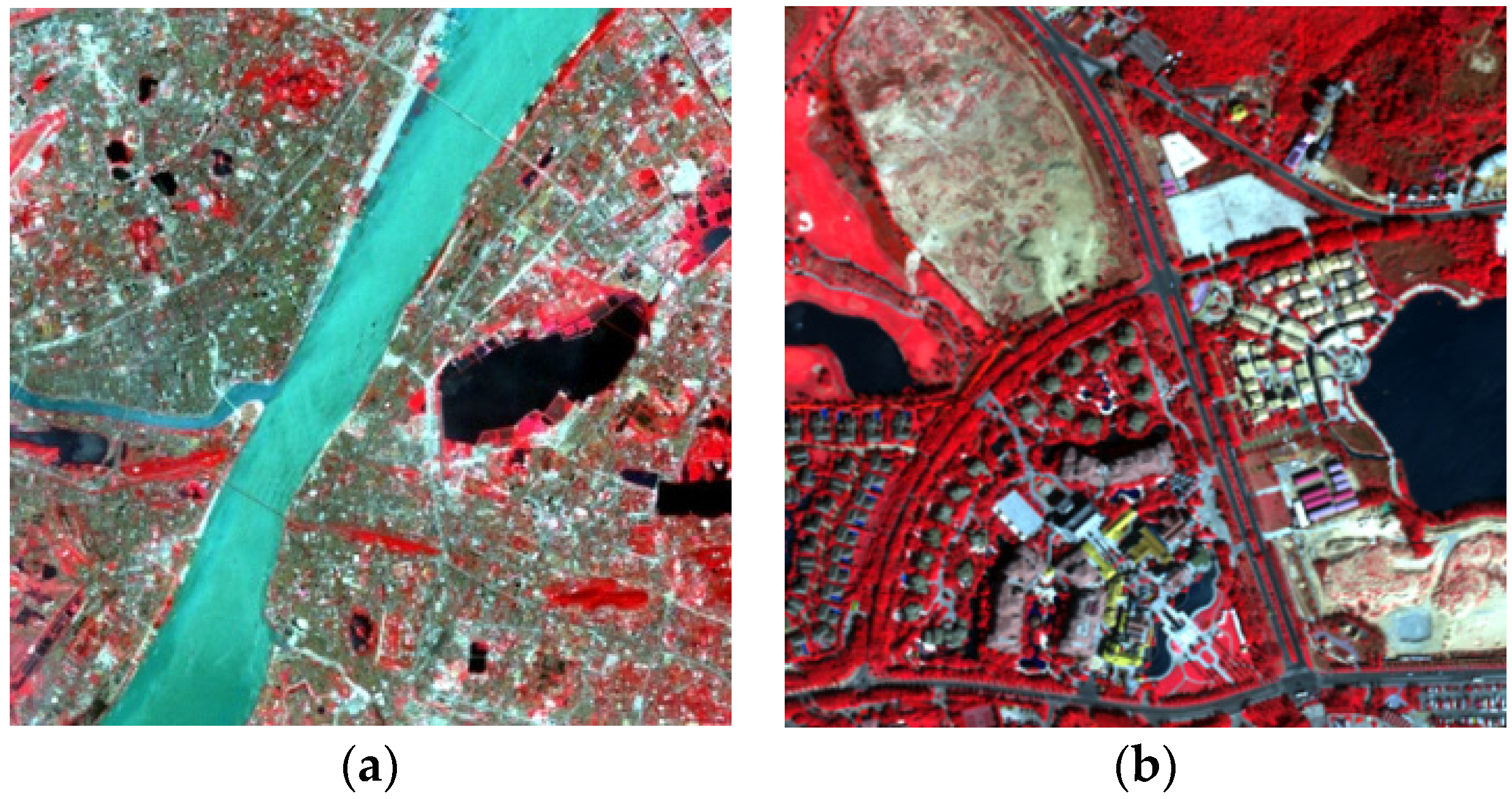
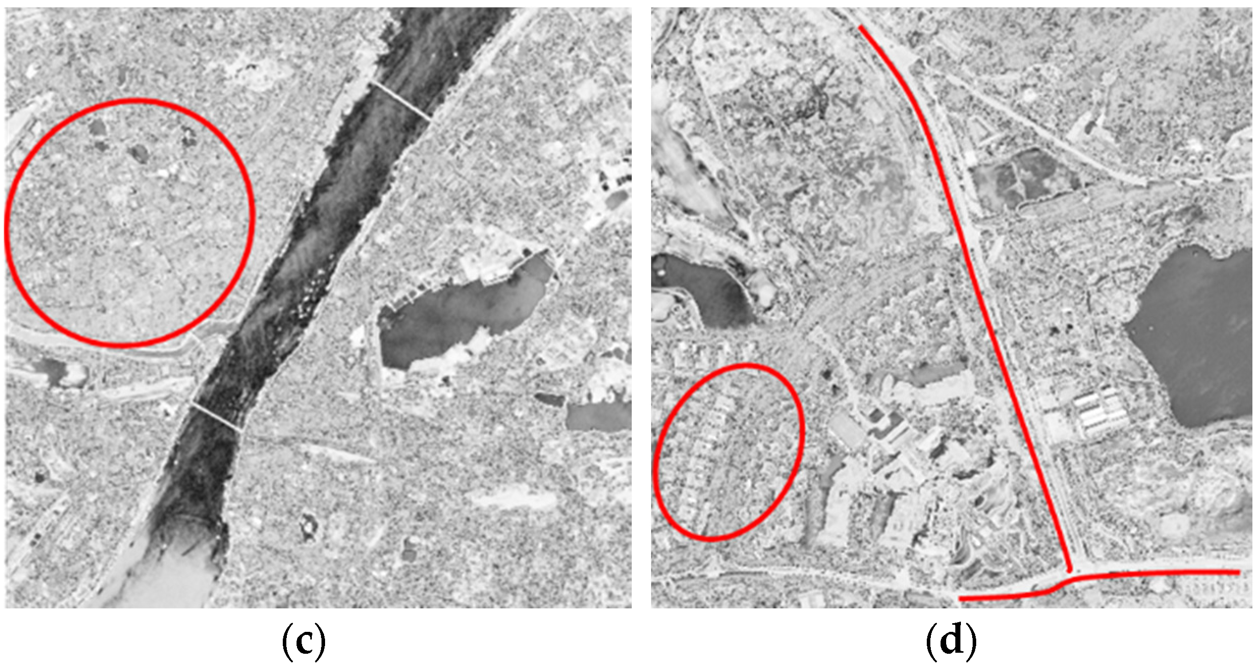
By directly applying FCM on the whole remote sensing image, the adaptive determination method in KADESFC does not take the local information of each pixel into consideration. It does not consider the situation that there are different distributions of objects in different regions of the remote sensing images with large scale. Thus, the membership matrix based on FCM may be unsatisfying when the remote sensing image with large scale is to be processed. Then, the inaccurate membership uik cannot be used to accurately estimate the entropy Ek and the weight parameter αk. Figure 3 shows the weight parameter image αk of two remote sensing images with a size of 400 × 400, which are acquired using the above adaptive determination method in KADESFC. It should be noted that the darker the pixel is, the smaller the weight parameter is, and vice versa. As can be seen from Figure 3c,d, some detailed pixels (building and roads labelled with circles and lines) are assigned with large value of the weight parameter, resulting in the fact that these detailed pixels may be smoothed in the final clustering results.
(2)
The objective functions of FCM_S and FCM_S1, namely Jm_S and Jm_S1, are both minimized by calculating the membership and cluster center iteratively, whose performance are often affected by the initial values. That is, their performance is limited by optimization of the clustering objective function.
Figure 3. The weight parameter images of adaptive determination method (KADESFC) (circles and lines representing building and roads). (a) Wuhan TM image; (b) Fancun image; (c) the weight parameter image of Wuhan TM image; and (d) the weight parameter image of Fancun image.
Remotesensing 08 00124 g003aRemotesensing 08 00124 g003b

3. The Proposed Method

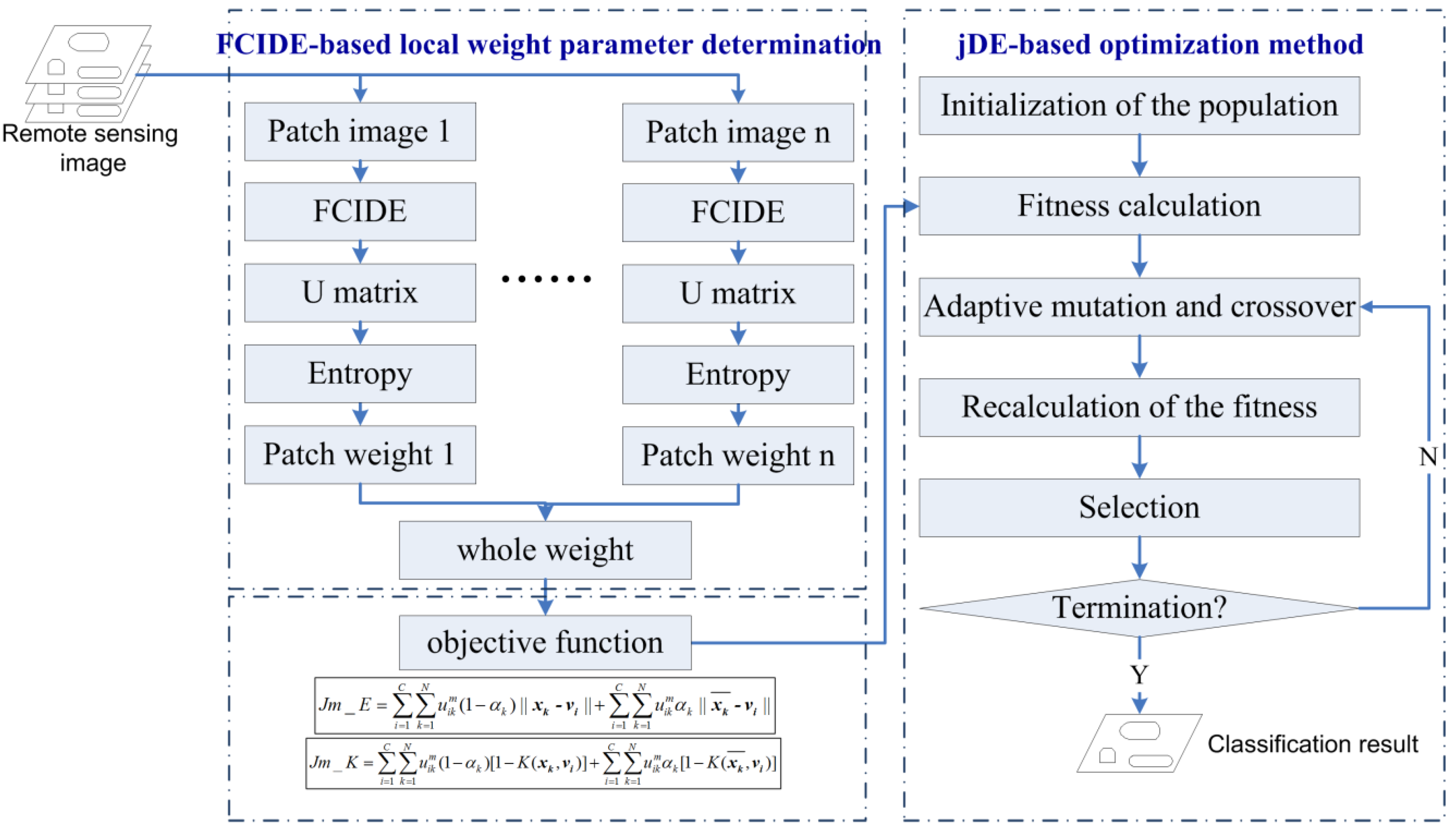
In this paper, spectral-spatial clustering with a local weight parameter determination method for remote sensing image (i.e., L-SSC) was proposed. The flowchart of L-SSC is as Figure 4, which includes two processes: FCIDE-based local weight parameter determination, and the jDE-based optimization method.
Figure 4. Flowchart of the proposed method L-SSC.
Remotesensing 08 00124 g004

3.1. FCIDE-Based Local Weight Parameter Determination Method

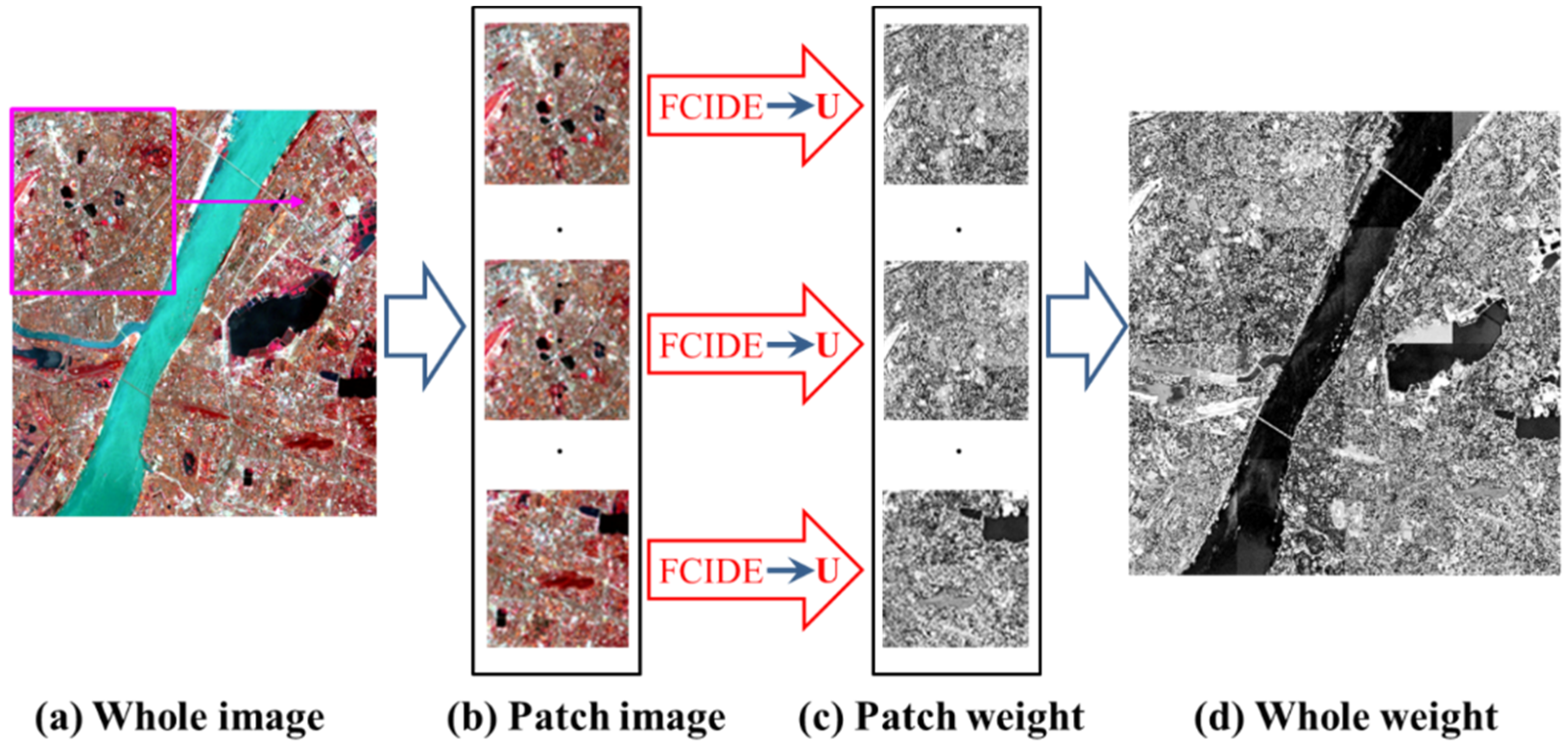
The local information, i.e., there are different distributions of objects in different regions, motivates us to determine the weight parameter based on patch image instead of the whole remote sensing image. Thus, the workflow of the proposed FCIDE-based local weight parameter determination method is listed as Figure 5 and will be described in detail below.
Figure 5. The flowchart of FCIDE-based local weight parameter determination method. (a) Whole image; (b) Patch image; (c) Parch weight; and (d) Whole weight.
Remotesensing 08 00124 g005
Step 1. The original image (see Figure 5a) with a large scale is divided into patch and patch image with small scale (see Figure 5b).
Step 2. Due to the fact that the cluster number of each patch image is unknown, the automatic clustering strategy in FCIDE [19] is used to cluster each patch of the remote sensing image and calculate the membership uik, which can be briefly described below.
(1)
Initialization of the population.
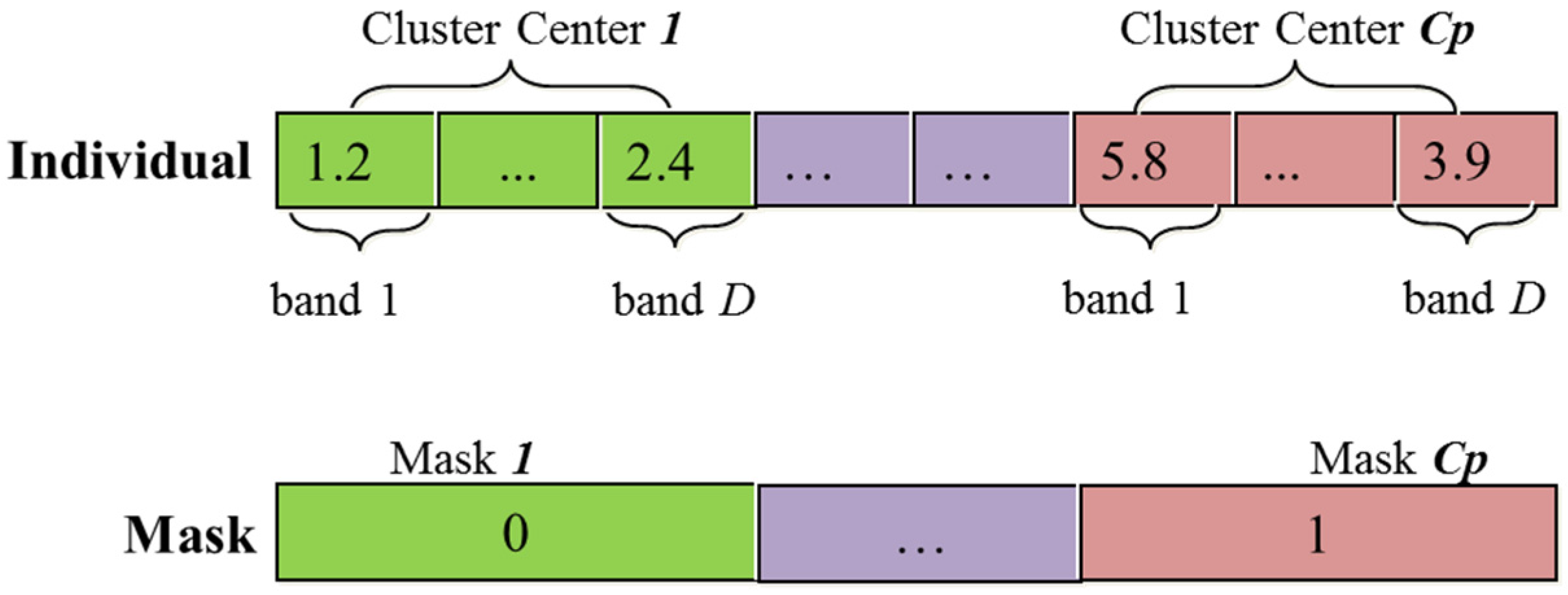
For a remote sensing image with C clusters and D spectral bands, the individual encoding strategy of FCIDE is as Figure 6, in which Cp cluster centers a are encoded (Cp > C) and D bands are encoded for each cluster center. At the same time, each individual have Cp masker corresponding to the Cp cluster centers. If the masker number is 1, the corresponding cluster center is selected to calculate the objective function, namely XB index Equation (11). If the masker number is 0, the corresponding cluster center is not selected to calculate the objective function. The task of FCIDE is to evolve C cluster centers, which possess the minimum value of XB.
Figure 6. The encoding strategy in automatic clustering.
Remotesensing 08 00124 g006
(2)
Calculation of the fitness of each individual using the objective function Equation (11):
X B = J m / N S e p ( v ) = i = 1 C k = 1 N u i k m x k v i 2 N min i j v i v j 2
In the FCIDE-based patch weight parameter calculation method, the clustering validity index XB [32] (see Equation (11)) was selected as the fitness function for the automatic clustering method FCIDE. It has been proved that the minimum of XB cannot only indicate the appropriate partition of remote sensing data, but also indicate the correct number of clusters.
(3)
Mutation and crossover. In DE, the mutation operator amounts to creating a donor vector Vi(t)=[vi,1(t), vi,2(t),…, vi,C×D(t)]T for changing each individual of the population. The mutation process can be expressed as Equation (12):
V i ( t ) = X r 1 i ( t ) + F ( X r 2 i ( t ) X r 3 i ( t ) )
where X r 1 i , X r 2 i , X r 3 i are picked up randomly from the population.
After the mutation operator, crossover is operated between the donor vector Vi(t) and the target vector Xi(t), generating a trial vector Ui(t) = [ui,1(t), ui,2(t),…, ui,C×D(t)]T. The crossover operator can be implemented as Equation (13):
u i , j ( t ) = { v i , j ( t ) , i f ( r a n d i , j ( 0 , 1 ) C R o r j = j r a n d ) x i , j ( t ) , o t h e r w i s e
There are two main parameters including F and CR in DE. In FCIDE, this scale factor F is varied in a random manner in the range (0.5–1) by using Equation (14). In addition, the crossover rate CR was linearly decreased with time from maximum to minimum of CR, which can be formulated as Equation (15):
F = 0.5 ( 1 + rand ( 0 , 1 ) )
C R = C R max ( C R max C R min ) × i t e r M A X I T E R
where CRmax and CRmin are the maximum and minimum values of the crossover rate CR, iter is the current iteration number, and MAXITER is the maximum number of allowable iterations.
(4)
Recalculation of the fitness of offspring Ui(t) using the objective function Equation (11).
(5)
Selection. The selection operator is to decide who is the winner between the target vector Xi(t) and the trial vector Ui(t). The vector with better fitness can be selected to the next generation. The target vector of next generation can be generated by selection operator as Equation (16):
X i ( t + 1 ) = { U i ( t ) , i f f ( U i ( t ) ) f ( X i ( t ) ) X i ( t ) , o t h e r w i s e
(6)
Elite strategy. In order to speed the coverage of iteration and enhance the efficiency of optimization, elite strategy is applied, which preserves the individual with the best fitness found so far.
(7)
Terminal condition. Repeat Step (3) to Step (6) until the terminal condition is met. The terminal condition is to reach the max number of iterations.
Step 3. After applying FCIDE to each patch (Figure 5b) of remote sensing image, the membership matrix U = [uik] can be acquired based on the cluster centers encoded in the individuals. Afterwards, the patch weight parameter (Figure 5c) can be calculated using Equations (9) and (10). Then the weight parameters of the whole image (Figure 5d) can also be obtained by combining these patch weight images.

3.2. jDE-Based Clustering Method (Optimization of the Proposed Kernelized Objective Function)

Based on the above local weight parameter αk, the first objective function Jm_E can be formulated as Equation (17), in which the Euclidian distance is used as the similarity metrics:
J m _ E = i = 1 C k = 1 N u i k m ( 1 α k ) | | x k v i | | + i = 1 C k = 1 N u i k m α k | | x k ¯ v i | |
where the weight parameter αk is used to control the effect of the neighbor term of k-th pixel, which has been calculated by the FCIDE-based local weight parameter determination method described in Section 3.1.
Considering the complex distribution of remote sensing data, the second objective function Jm_K, a kernelized version of Jm_E, was also constructed as Equation (18), in which the kernel distance was used as the similarity metric:
J m _ K = i = 1 C k = 1 N u i k m ( 1 α k ) [ 1 K ( x k , v i ) ] + i = 1 C k = 1 N u i k m α k [ 1 K ( x k ¯ , v i ) ]
where K(xk, vi) is the kernel metric distance between xk and vi based on Radial Basis Function (RBF) kernel [33], the formula of which is shown in Equation (19):
K ( x k , v i ) = exp ( | | x k v i | | 2 2 × δ 2 )
where δ is bandwidth, which has an effect on the performance of the kernel metric. In the paper, the bandwidth is empirically selected as the number of spectral bands.
In this paper, a variant of DE, namely jDE [30], is used to optimize the objective function Equation (17), or Equation (18), respectively. The whole optimization process of jDE can be implemented according to the following steps:
Step 1. Initialization of the population. For a remote sensing image with C clusters and D spectral bands, the individual encoding strategy of FCIDE is as Figure 7, in which C cluster centers are encoded and D bands are encoded for each cluster center. Considering the adaptive mutation and crossover in Step 3, the mutation scale factor F, and the crossover constant CR are also encoded into the individual.
Figure 7. The example of individual encoding in jDE (e.g., K cluster centers and two bands).
Remotesensing 08 00124 g007
Step 2. Calculation of the fitness of each individual using the objective function Equation (17) or Equation (18).
Step 3. Adaptive mutation and crossover. In DE, the mutation operator amounts to creating a donor vector Vi(t) = [vi,1(t), vi,2(t),…, vi,C×D(t)]T for changing each individual of the population. The mutation process can be expressed as Equation (20):
V i ( t ) = X r 1 i ( t ) + F i ( X r 2 i ( t ) X r 3 i ( t ) )
where X r 1 i , X r 2 i , X r 3 i are picked up randomly from the population.
After mutation operator, crossover is operated between the donor vector Vi(t) and the target vector Xi(t), generating a trial vector Ui(t) = [ui,1(t), ui,2(t),…, ui,C×D(t)]T. The crossover operator can be implemented as Equation (21):
u i , j ( t ) = { v i , j ( t ) , i f ( r a n d i , j ( 0 , 1 ) C R i o r j = j r a n d ) x i , j ( t ) , o t h e r w i s e
There are two main parameters including F and CR in DE. As is shown in Figure 6, each individual not only encodes the cluster centers but also the parameters CR and F enabling their update in the process of evolution. The Fi and CRi can be updated according to Equation (22) and Equation (23):
F i ' = { 0.1 + 0.9 × r a n d ( 0 , 1 ) , i f r a n d ( 0 , 1 ) < 0.1 F i ,          o t h e r w i s e
C R i ' = { r a n d ( 0 , 1 ) ,    i f r a n d ( 0 , 1 ) 0.1 C R i ,     o t h e r w i s e
Step 4. Recalculation of the fitness of offspring Ui(t) using the objective function Equation (17) or (18).
Step 5. Selection. The selection operator is to decide who is the winner between the target vector Xi(t) and the trial vector Ui(t). The vector with better fitness can be selected to the next generation. The target vector of next generation can be generated by selection operator as Equation (24):
X i ( t + 1 ) = { U i ( t ) , i f f ( U i ( t ) ) f ( X i ( t ) ) X i ( t ) , o t h e r w i s e
Step 6. Elite strategy. In order to speed the coverage of iteration and enhance the efficiency of optimization, elite strategy is applied, which preserves the individual with the best fitness found so far.
Step 7. Terminal condition. Repeat Steps 3 to step 6 until the terminal condition is met. The terminal condition is to either reach the max number of iterations or begin to stagnate in order to update the best individual.
Step 8. Clustering. The membership matrix U = [uik] corresponding to the best individual is calculated based on the cluster center encoded in the best individual. Each pixel is then assigned to the cluster center with the largest membership uik using Equation (25):
y k = arg max 1 i C u i k
where yk is the cluster label of the k-th pixel, C is the number of clusters.

4. Experimental Data and Results

4.1. The Comparison Methods and Parameter Setting

The proposed methods (i.e., L-SSC_E, and L-SSC_K) were compared with other clustering methods, including classical clustering methods (i.e., K-means, FCM [14], Gaussian Mixture Model (GMM)) and spectral-spatial clustering methods (i.e., FCM_S1 [16], KWFLICM [31], KADESFC [17]). It should be noted that L-SSC_E, and L-SSC_K are the methods that use Equations (17) and (18) as the objective function, respectively. In addition, principal component analysis (PCA) was applied to the remote sensing image before GMM was conducted in order to remove the correlation between different spectral bands and to better approximate the inverse of the covariance matrix in GMM. For KADESFC, L-SSC_E, and L-SSC_K, the size of the population is 5 × D [34] for Wuhan TM and Fancun Quickbird image, where D is the number of the spectral bands for the remote sensing image. In order to reduce the computational complexity, the size of population is set as 50 for the Indian Pine AVIRIS image. The max generation for KADESFC, L-SSC_E, and L-SSC_K is 100. For L-SSC and the comparison methods, the cluster number was set to be the class number in the ground truth

4.2. Experiment 1—Wuhan TM Image

In order to test the validity of proposed algorithm, a Wuhan TM image is used, which is a 30 m resolution multi-spectral Landsat TM image of Wuhan City, China with a size of 400 pixel × 400 pixel, in six bands. This region in the Wuhan TM image was expected to contain five classes, which are listed in Table 1. It also reports the details of the samples for the Wuhan TM image. The Wuhan TM image and ground truth image are shown in Figure 8a,b.
Figure 8c–j illustrates the clustering results using K-means, FCM, PCA+GMM, FCM_S1, KWFLICM, KADESFC, L-SSC_E, and L-SSC_K, respectively. As can be seen from Figure 8, these clustering methods, except K-means, achieve similar clustering results on the river and lake classes due to their simple characteristics. For the FCM method, the vegetation and building classes are classified incorrectly and the bare soil class is classified into two classes. In addition, for GMM, some pixels are misclassified into the building class. In addition, compared with the clustering results of K-means, FCM, and PCA+GMM with more isolated pixels, the other clustering methods give better visual results due to the utilization of spatial information. Compared with KADESFC, the clustering results of L-SSC_E and L-SSC_K perform better, especially in the building class in the left part of the image, resulting from that the weight parameter calculated by the patch image which takes the local information into consideration and can be more accurate.
Figure 8. Wuhan TM image and the clustering results. (a) WuhanTM image; (b) Groundtruth; (c) K-means; (d) FCM; (e) PCA+GMM; (f) FCM_S1; (g) KWFLICM; (h) KADESFC (i) L-SSC_E and (j) L-SSC_K.
Remotesensing 08 00124 g008
Table 1. Details of the samples for the Wuhan TM image.
Class NameRiverVegetationLakeBareBuilding
Test Samples25574102173718493037
To compare the algorithms above quantitatively, overall accuracy (OA) and kappa coefficient [35,36] for the image are listed in Table 2. L-SSC_K obtains the best OA, 92.41%, with the gain of 20.41%, 10.89%, 0.31%, 6.3%, 1.92%, 4.84%, and 0.38% over K-means, FCM, PCA+GMM, FCM_S1, KWFLICM, KADESFC, and L-SSC_E, respectively. In most cases, the SSC clustering methods (i.e., FCM_S1, KWFLICM, KADESFC, and L-SSC_E) can achieve higher clustering accuracy due to the utilization of spatial information. We can also see that PCA+GMM get relative high clustering accuracy on about 92%. This is because that the PCA was firstly applied, resulting in a distinctive data structure compared with the original one. In addition, compared with KADESFC (OA = 87.57%), the clustering results of L-SSC_E (OA = 92.03%) and L-SSC_K (OA = 92.41%) achieve higher clustering accuracy, which also demonstrate the effectiveness of the local weight parameter determination method and its capability of better balancing the trade-off between the spectral term and spatial term. Although KWFLICM was designed to determine the weight parameter based on the local window, it cannot get higher clustering accuracy on the Wuhan TM image. This is because KWFLICM was originally designed for the natural image segmentation, in which there only exists one spectral band and the adaptive determination strategy of weight parameter and bandwidth in KWFLICM do not take the multi-spectral bands into consideration. Compared with L-SSC_E, the clustering result of L-SSC_K performs a little better, which demonstrates the effectiveness of kernel technique for kernelizing the objective function. The quantitative comparison of these algorithms is consistent with the visual finding. Based on the above analysis, L-SSC_E and L-SSC_K outperform other clustering methods.
Table 2. Comparison of clustering accuracy for Wuhan TM image.
ClassK-MeansFCMPCA+GMMFCM_S1KWFLICMKADESFCL-SSC_EL-SSC_K
--Producer’s Accuracy (%)
River100.00100.00100.00100.00100.00100.00100.00100.00
Vegetation85.3182.3193.8388.9991.1789.7893.4693.29
Lake099.8195.00100.0099.9499.94100.00100.00
Bare soil78.4360.8894.7671.0986.8075.2488.3494.93
Building49.5871.7268.1372.0972.1573.9575.5166.87
--User’s Accuracy (%)
River62.0399.96100.00100.00100.00100.00100.00100.00
Vegetation92.1274.9698.5181.9492.0484.4496.2996.59
Lake091.85100.0095.8299.9485.3282.4986.51
Bare soil75.5067.0980.9875.6079.6683.2787.5385.45
Building96.8385.1779.8284.2283.8885.9788.5490.86
OA (%)71.7081.5292.1086.1190.4987.5792.0392.41
Kappa0.63170.76000.89760.81960.87690.83900.89710.9095

4.3. Experiment 2—Fancun QuickBird Image

The second experiment dataset (Fancun QuickBird dataset) [37] was a 2.4-m spatial resolution QuickBird (QB) image (400 × 400) over the Fancun area in Hainan province, China, which was acquired in January 2010. This remote sensing dataset has been used for testing a remote sensing image supervised classification method in [37]. However, the ground truth in [37] is not appropriate for remote sensing image clustering because of the fact that the number of shadow pixels is so small that it is difficult to distinguish the shadow class and water class in the process of clustering. Hence, in this paper, for the task of remote sensing image clustering, the shadow class and water class are merged into one class in the ground truth for testing the clustering performance. In addition, a new concrete class is added into the ground truth due to its large amount. Figure 9a,b show the Fancun image and its corresponding ground truth. Table 3 reports the number of test samples.
Figure 9. Fancun image and its clustering results. (a) WuhanTM image; (b) Groundtruth; (c) K-means; (d) FCM; (e) PCA+GMM; (f) FCM_S1; (g) KWFLICM; (h) KADESFC; (i) L-SSC_E and (j) L-SSC_K.
Remotesensing 08 00124 g009
Table 3. Details of the samples for the Fancun image.
Class NameWater + ShadowTreeBareGrassBuildingRoadConcrete
Test Samples10,98625,24244654052823339311951
Figure 9c–j illustrates the clustering results using K-means, FCM, PCA+GMM, FCM_S1, KWFLICM, KADESFC, L-SSC_E, and L-SSC_K, respectively. As can be seen from Figure 9, compared with FCM, KWFLICM, and FCM_S1, the five other algorithms can distinguish the road class (labelled 2) better, especially for KADESFC, L-SSC_E and L-SSC_K. As for the tree class (labelled 1), some pixels in K-means, KWFLICMand FCM_S1 are misclassified into grass class. The results of L-SSC_E, L-SSC_K, and KADESFC look better. As for the grass class (labelled 3), some pixels in KADESFC are misclassified into the tree class while L-SSC_E, L-SSC_K can achieve better visual result, demonstrating the efficiency of the local weight parameter calculated by the patch image. The above comparisons can demonstrate that the proposed SSC method can not only incorporate the spatial information into the clustering result, it can also preserve the details of the image with the local weight parameter.
The Overall Accuracy (OA) and kappa coefficient for the image are also listed in Table 4. L-SSC_K obtains the best OA, 76.18%, with the gain of 10.15%, 12.58%, 9.74%, 9.07%, 7.06%, 3.38%, and 0.88% over K-means, FCM, PCA+GMM, FCM_S1, KWFLICM, KADESFC, and L-SSC_E, respectively. Compared with KADESFC with the clustering accuracy at 72.80%, the clustering results of L-SSC_E and L-SSC_K can get clustering accuracy at 75.30%, and 76.18%, which demonstrate the effectiveness of the local weight parameter calculated by the patch image. In addition, the clustering result of L-SSC_K can achieves slightly higher clustering accuracy than L-SSC_E, which demonstrates the effectiveness of the kernel technique. Especially for tree, grass, and road classes, L-SSC_E (78.05%, 96.13%, 77.94%) and L-SSC_K (84.72%, 97.33%, 77.44%) both achieve comparative Producer’s Accuracy (PA), which are consistent with the above visual result. The quantitative comparison of these algorithms is consistent with the visual finding.
Table 4. Comparison of clustering accuracy for the Fancun image.
ClassK-MeansFCMPCA + GMMFCM_S1KWFLICMKADESFCL-SSC_EL-SSC_K
--Producer’s Accuracy (%)
Water and shadow99.2099.3881.6299.3399.5299.5199.7099.60
Tree58.8455.5158.5958.8466.9285.9378.0584.72
Grass98.0196.2297.9897.2598.5022.5196.1397.33
Bare46.8762.4998.1061.2372.7561.6244.8967.87
Building26.0436.2143.5035.2043.4820.8732.2426.28
Road74.3120.2286.9253.420.0078.1777.9477.44
Concrete90.8897.44098.1599.1899.0899.7495.23
--User’s Accuracy (%)
Water and shadow78.4579.0299.9986.0787.2277.1480.9983.99
Tree99.4499.1899.6299.3599.3986.3999.4699.47
Grass34.3551.6848.7048.2636.0650.7673.5862.18
Bare43.7949.2067.8749.7550.0753.8150.1249.30
Building51.3055.2579.7959.7649.7460.9461.4232.93
Road52.759.8348.3224.960.0051.0150.8746.59
Concrete54.7748.08048.0747.7946.9344.1750.72
OA (%)66.0363.6066.4467.1169.1272.800.753076.18
Kappa0.57930.55180.59140.59400.61130.63650.68430.6920

4.4. Experiment 3—Indian Pine AVIRIS Image

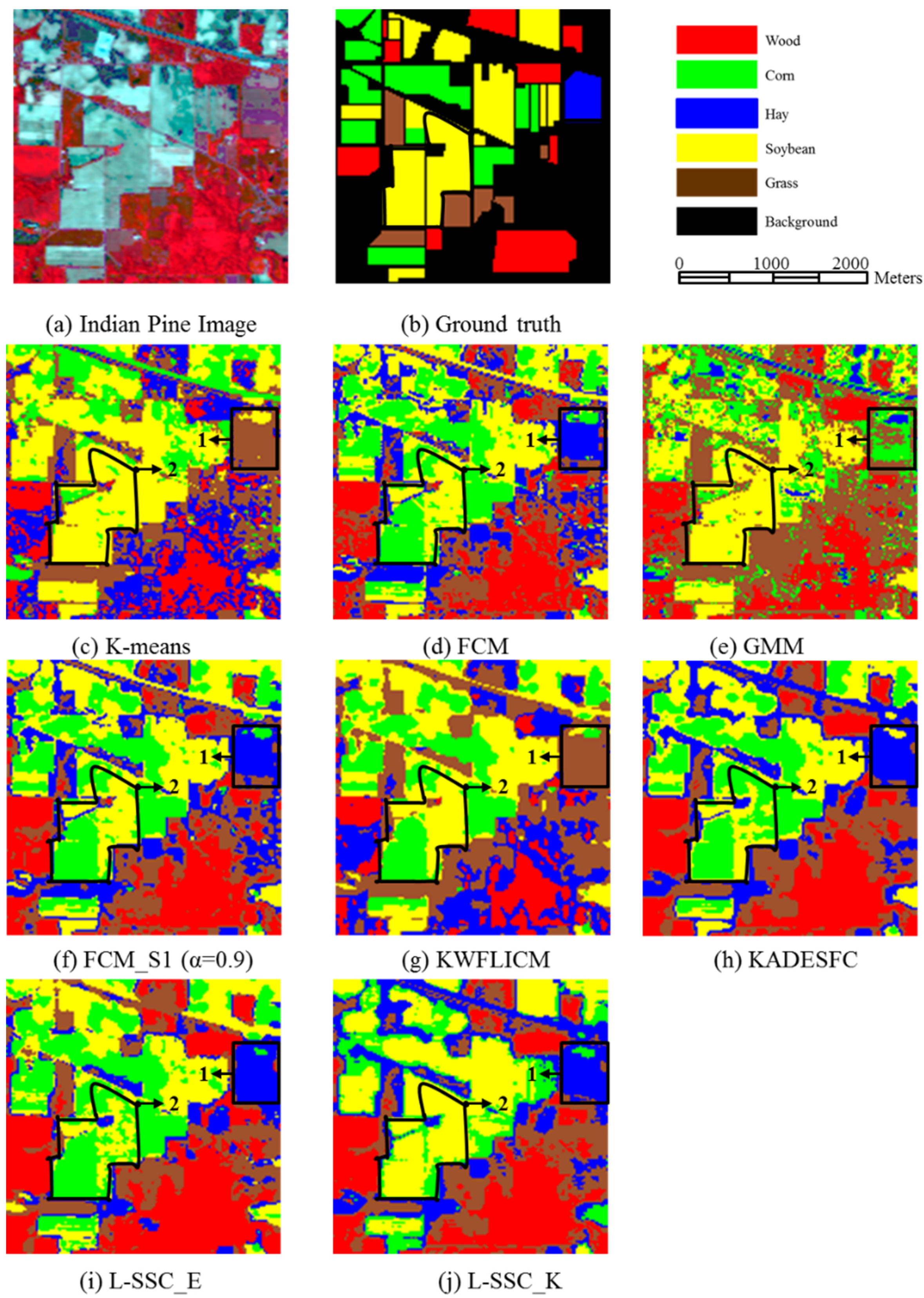
Experiment 3 was conducted using an Airborne Visible/Infrared Imaging Spectrometer (AVIRIS) dataset from over the Northwest India Indian Pine test site by the Jet Propulsion Laboratory and NASA/Ames in June 1992, which was captured from six miles in the western area of Northwest Tippecanoe County (NTC). This AVIRIS image with a size of 145 pixels by 145 pixels represents a 2 mile × 2 mile area at 20 m spatial resolution. A total of 20 channels from the water absorption and noisy bands (104–108, 150–163, 220) were removed from the original 220 spectral channels, leaving 200 spectral features for the experiments. For the indication of clustering task, we referred to the strategy in [38] to merge the land cover classes to get the ground truth composed of five classes including wood, corn, hay, soybean, and grass. Figure 10a,b show the Indian Pine AVIRIS image and its corresponding ground truth. Table 5 reports the number of test samples for the five classes.
Table 5. The number of the test samples used for the Indian Pine image.
Class NameWoodCornHaySoybeanGrass
Test Samples249521344784020963
Figure 10. Indian Pine AVIRIS image and its clustering results. (a) WuhanTM image; (b) Groundtruth, (c) K-means; (d) FCM; (e) PCA+GMM; (f) FCM_S1; (g) KWFLICM; (h) KADESFC; (i) L-SSC_E and (j) L-SSC_K.
Remotesensing 08 00124 g010
Figure 10c–j illustrates the clustering results using K-means, FCM, PCA+GMM, FCM_S1, KWFLICM, KADESFC, L-SSC_E, and L-SSC_K, respectively. As can be seen from Figure 10, in the region labelled 1, K-means, PCA+GMM, and KWFLICM misclassify the hay class into the grass class. The results of other methods, especially for L-SSC_E and L-SSC_K, look better. In the region labelled 2, some pixels in the results of FCM, FCM_S1, KWFLICM, KADESFC, and L-SSC_E misclassify the soybean class into the corn class. Totally, the proposed method L-SSC_K can acquire comparative visual result on both regions labelled 1 and 2. The Overall Accuracy (OA) and kappa coefficient for the image are also listed in Table 6. L-SSC_K obtains the best OA, 63.49%, with the gain of 12.67%, 9.65%, 6.94%, 9.52% 6.51% and 2.16% over K-means, FCM, PCA+GMM, FCM_S1, KWFLICM, KADESFC, and L-SSC_E, respectively. Especially, L-SSC_K achieves the comparative producer’s accuracy on both soybean and corn classes, which is consistent with the above visual results. Compared with KADESFC (OA = 57.98%), the clustering results of L-SSC_E (OA = 62.33%) and L-SSC_K (OA = 64.49%) perform better due to the fact that the local weight parameter calculated by the patch image can better describe the relation between different pixels. In addition, Compared with L-SSC_E, the clustering result of L-SSC_K get higher clustering accuracy, which demonstrates the effectiveness of the kernel technique. The quantitative comparison of these algorithms is consistent with the visual finding. As can be seen from the above analysis, the comparisons of these algorithms for the Indian Pine AVIRIS image also agree with the Wuhan TM and Fancun Quickbird image. The same conclusion can be made that L-SSC_E and L-SSC_K outperform other clustering methods.
Table 6. Comparison of clustering accuracy for Indian Pine AVIRIS image.
ClassK-MeansFCMPCA+GMMFCM_S1KWFLICMKADESFCL-SSC_EL-SSC_K
--Producer’s Accuracy (%)
Wood20.0453.1926.9753.5950.4650.2660.5232.02
Corn50.8063.5965.3268.1448.5976.6279.976.01
Hay079.7110.4688.280.0092.0594.9890.38
Soybean72.6653.2367.1454.6360.0546.7946.0276.29
Grass75.1834.0695.0241.3386.8166.4679.9660.96
--User’s Accuracy (%)
Wood32.2042.6035.2743.0644.3939.3441.6251.05
Corn97.1396.86100.0097.0698.9599.3394.7798.30
Hay025.0814.0129.870.0034.4660.7832.24
Soybean58.7866.6963.4367.4766.2861.6166.1265.86
Grass46.7738.7742.0548.6047.9669.1168.8766.86
OA (%)51.8254.8456.8057.5554.9757.9862.3364.49
Kappa0.33410.39980.41120.43370.39500.44120.49690.5126

5. Discussion

5.1. Discussion on Selection of Patch Size

The patch size has an impact on the performance of the proposed method L-SSC. Therefore, we discuss the selection of patch size visually and quantitatively based on the weight parameter image and clustering accuracy of different patch sizes.
(1)
Visual Comparison (Weight Parameter Image) of Different Patch Sizes
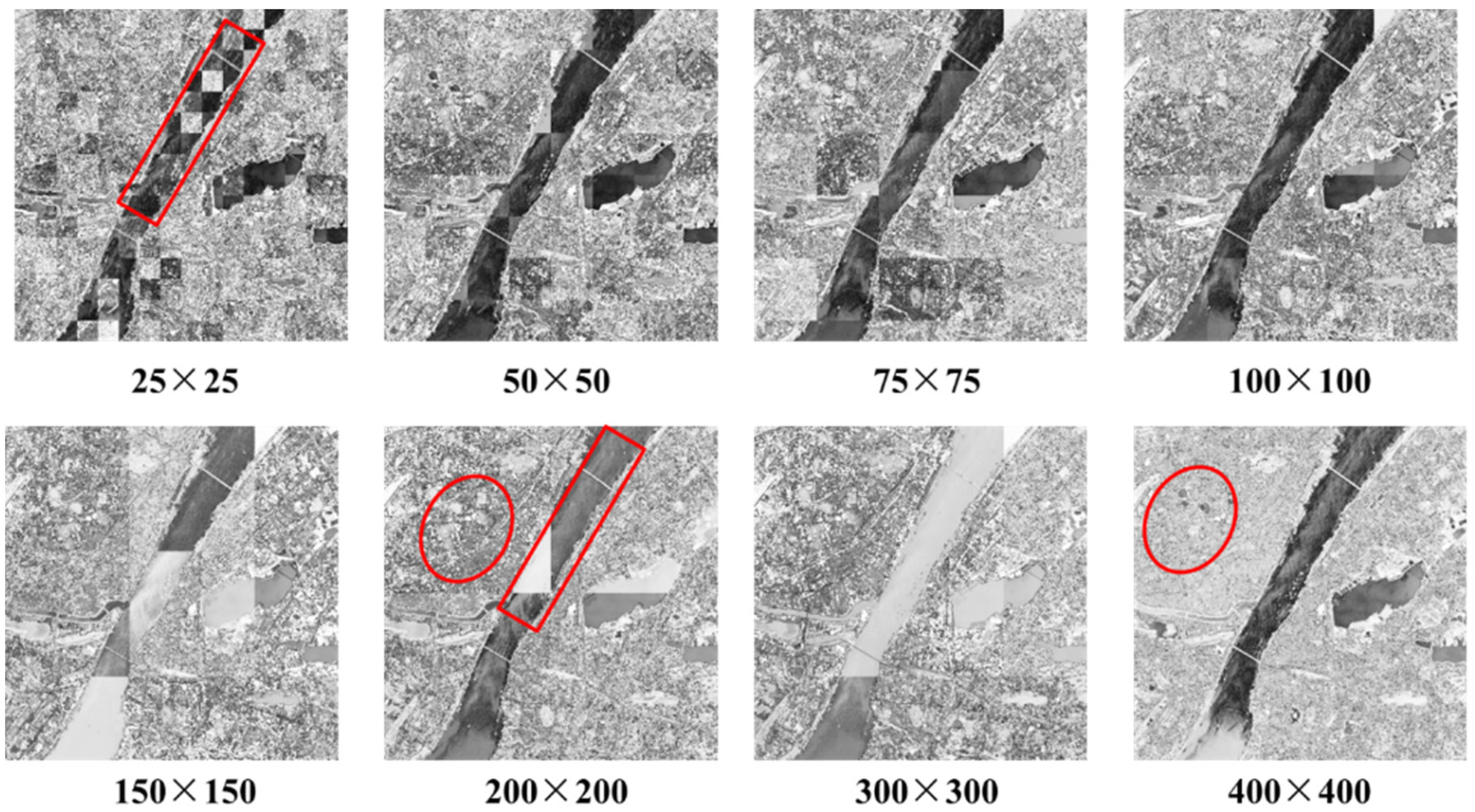
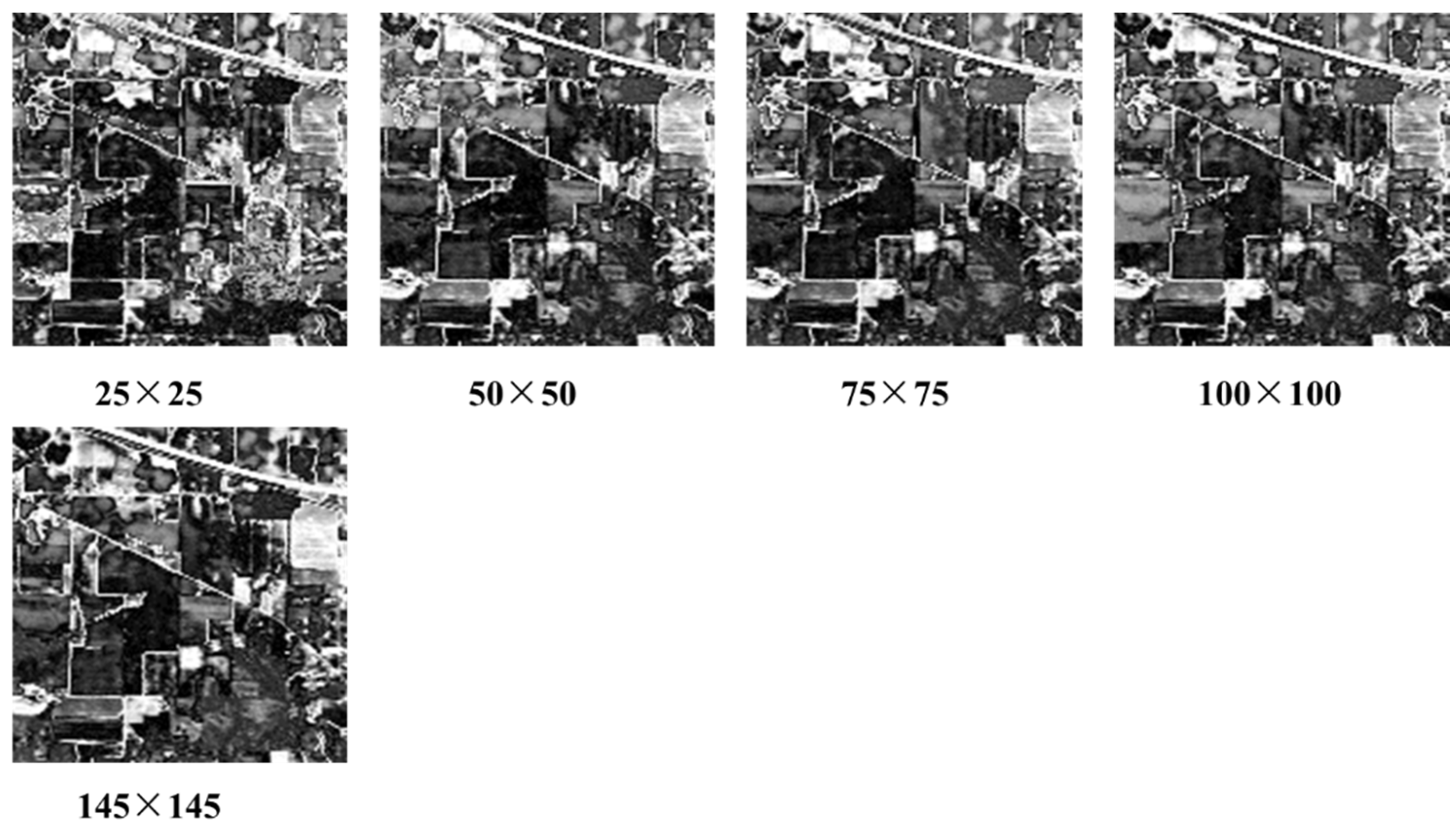
For Wuhan TM, Fancun Quickbird, and Indian Pine AVIRIS images, Figure 11, Figure 12 and Figure 13 list the weight parameter images based on different patch sizes including 25 × 25, 50 × 50, 75 × 75, 100 × 100, 145 × 145, 150 × 150, 200 × 200, 300 × 300, and 400 × 400. In Figure 11, Figure 12 and Figure 13, the darker the pixel is, the smaller the local weight parameter value is, and vice versa. It should be noted that the patch size of 400 × 400 for Wuhan TM or Fancun Quickbird, and 145 × 145 for Indian Pine AVIRIS image is equal to the size of the corresponding whole image. Thus, the comparison between 400 × 400 for Wuhan TM or Fancun Quickbird and 145 × 145 for Indian Pine AVIRIS image with other patch sizes can be used to demonstrate the effectiveness of FCIDE-based local weight parameter determination method.
Figure 11. The weight parameter image of the Wuhan TM image for different patch sizes (refer to the text for a detailed description of the markup).
Remotesensing 08 00124 g011
Figure 12. The weight parameter image of the Fancun image for different patch sizes (refer to the text for a detailed description of the markup).
Remotesensing 08 00124 g012
Figure 13. The weight parameter image of the Indian Pine image for different patch sizes.
Remotesensing 08 00124 g013
For the Wuhan TM image in Figure 11, the pixels in the region (labelled red circle) belong to town, which has a variety of objects. However, when the patch size is 400 × 400, these pixels are assigned excessive weight parameter values, which can result in over-smoothing. That is, the complex distribution of objects in this region may be smoothed due to the excessive weight parameter value calculated by whole image. When the patch size is smaller than 200 × 200, the weight parameter value in these regions become small, which can prevent over-smoothing. We also can see that when the patch size is equal to 25 × 25, or 50 × 50 (labelled red rectangle), mosaic appearance will emerge, which are not in line with the real situation. Therefore, based on visual comparison of different patch sizes, the patch size (75 × 75–200 × 200) is much preferred for the Wuhan TM image. For the Fancun image in Figure 12, when the patch size is 400 × 400, the building class (labelled red circle) is assigned an excessive weight parameter value, compared with the weight parameter calculated by a patch image with 100 × 100. Moreover, as for the road class (labelled red lines), the weight parameter value is relatively small (i.e., dark) when patch size is equal to 100 × 100, compared with weight parameter calculated by the whole image (400 × 400), in which the weight parameter value of these pixels is excessive and unacceptable, resulting in the smoothing of the road class. Furthermore, like the Wuhan TM image, when the patch size is too small, a mosaic appearance (labelled red rectangle) will also emerge. For the Indian Pine AVIRIS image in Figure 13, due to the fact the shapes of the different farmlands is regular (e.g., rectangle) and with small area, it weakens the impact of the mosaic.
(2)
Quantitative Comparison (Clustering Accuracy) of Different Patch Sizes
Table 7, Table 8 and Table 9 show the clustering accuracy of L-SSC_E and L-SSC_K for different patch sizes, namely 25 × 25, 50 × 50, 75 × 75, 100 × 100, 145 × 145, 150 × 150, 200 × 200, 300 × 300 and 400 × 400.
Table 7. The clustering accuracy of different patch sizes for the Wuhan TM image.
Patch Size25 × 2550 × 5075 × 75100 × 100150 × 150200 × 200300 × 300400 × 400
--L-SSC_E
OA (%)82.1471.8079.7987.4692.0092.0382.7888.29
Kappa0.76870.64070.73700.83990.89690.89710.77720.8483
--L-SSC_K
OA (%)78.7981.4489.4991.5090.5891.7392.4187.48
Kappa0.72460.75870.86480.89010.87890.89260.90180.8379
Table 8. The clustering accuracy of different patch sizes for the Fancun image.
Patch Size25 × 2550 × 5075 × 75100 × 100150 × 150200 × 200300 × 300400 × 400
--L-SSC_E
OA (%)61.8271.2875.3670.4865.5475.3064.6867.4
Kappa0.52720.63710.67940.63070.57180.68430.53420.5922
--L-SSC_K
OA (%)63.6865.6976.1875.5667.0666.6264.8466.10
Kappa0.54940.57350.69200.68200.59390.58100.56480.5835
Table 9. The clustering accuracy of different patch sizes for the Indian Pine AVIRIS image.
Patch Size25 × 2550 × 5075 × 75100 × 100150 × 150
--L-SSC_E
OA (%)61.4762.3358.1457.3657.41
Kappa0.48140.49690.43070.43320.4322
--L-SSC_K
OA (%)61.0264.4960.3760.2963.63
Kappa0.48280.51260.45670.47340.4985
In Table 7, for the Wuhan TM image, it can be seen that L-SSC_E can acquire higher clustering accuracy when the patch size is 150 × 150–200 × 200, and L-SSC_K can perform better when the patch size is 75 × 75–300 × 300. In both above situations, they can achieve better clustering performance than the clustering result when the patch size is 400 × 400 (i.e., the whole image), validating the effectiveness of local weight parameter. On the other hand, when the patch size is small (e.g., 25 × 25, 50 × 50), their clustering accuracy is not so satisfying. To some extent, this is consistent with the visual comparison in Figure 11. Therefore, based on the visual and quantitative comparison, the optimal patch size for the Wuhan TM image can be 150 × 150–200 × 200. In Table 8, for the Fancun Quickbird image, the same conclusion can be made that the optimal patch size for the Fancun Quickbird image can be 75 × 75–200 × 200. It should be specified that, in Table 9, for the Indian Pine AVIRIS image, the optimal patch size is smaller (i.e., 50 × 50) due to the fact the regular shape and small size of farm land in the region decreases the impact of the mosaic, which is also consistent with the conclusion made in the visual comparison of different patch sizes in Figure 13.
Based on the visual and quantitative comparison of L-SSC for different patch sizes, it can be seen that L-SSC with the local weight parameter can achieve higher clustering accuracy than the method with the weight parameter calculated by the whole image (e.g., 400 × 400 for the Wuhan TM and Fancun Quickbird images, or 145 × 145 for the Indian Pine AVIRIS image). Especially, visual comparison shows that it can also preserve the detail of some classes, such as road and building. However, it is not so easy to select one optimal patch size for all remote sensing images due to the different characteristics of different images (e.g., the shape and size of objects). Firstly, when the patch is smaller, the more accurate local weight parameter can be acquired. However, more patch images mean that huge amounts of clustering results with different degrees of detail may emerge, resulting in the mosaic appearance (e.g., for Wuhan TM and Fancun Quickbird images). Therefore, in this situation, a middle-size (150 × 150–200 × 200) can be selected. Secondly, when the shape of the objects is regular (e.g., a rectangle for the Indian Pine AVIRIS image), the degree of detail of clustering results with different patch size is similar, weakening the impact of mosaic. Thus, for the Indian Pine AVIRIS image, a small patch size will be preferred (50 × 50).

5.2. Computational Complexity Analysis

The computational complexity of L-SSC is analyzed, which includes the parts: the FCIDE-based local weight parameter determination method, and the jDE-based clustering method.
Part 1: FCIDE-based local weight parameter determination method:
  • Initialization. The computational complexity of initialization is O ( N P 1 × C m a x ) , where N P 1 represents the number of individuals, C m a x is the maximum number of cluster numbers.
  • Fitness calculation. (a) Supposing there are N 1 pixels in each patch image, the computational complexity of this step is O ( N 1 × C m a x ) . (b) The time for updating the clusters is O ( C m a x ) . Thus, the total time that is spent on fitness calculation is O ( N P 1 × N 1 × C m a x ) .
  • Mutation and crossover operation. In this step, the time consumed is O ( N 1 × C m a x ) .
  • Selection. The selection operation’s time is O ( N P 1 ) .
The computational complexity for the FCIDE-based local weight parameter determination method is O ( N P 1 × N 1 × C m a x × iP × G 1 ) , namely O ( N P 1 × N × C m a x × G 1 ) , where iP is the number of patch images, and G 1 is the maximum generation for the FCIDE-based local weight parameter determination method, N is the number of pixels in the whole image.
Part 2: jDE-based clustering method:
  • Initialization. The time which this step needs is O ( N P × C ) , where N P represents the number of individuals, C is the number of cluster numbers.
  • Fitness calculation. (a) Supposing there are N pixels in the whole image, the computational complexity of this step is O ( N × C ) . (b) The time for updating the clusters is O ( C ) . Thus, the total time that is spent on fitness calculation is O ( N P × N × C ) .
  • Mutation and crossover operation. In this step, the time consumed is O ( N P × C ) .
  • Selection. The selection operation’s time is O ( N P ) .
The computational complexity for the jDE-based clustering method is O ( N P × N × C × G 2 ) , where G 2 is the maximum generation for the jDE-based clustering method.
Based on the above analysis, the computational complexity of L-SSC is O ( N P 1 × N × C m a x × G 1 ) or O ( N P × N × C × G 2 ) . The time consumed by each algorithm is shown in Figure 14. Although the computation cost of L-SSC is slightly more than KADESFC, it can be acceptable with regard to the clustering accuracy improvement.
Figure 14. Comparison of computational time for (a) Wuhan TM; (b) Fancun IKONOS; and (c) Indian Pine AVIRIS.
Remotesensing 08 00124 g014

6. Conclusions

This paper proposed spectral-spatial clustering with a local weight parameter determination method for remote sensing image, namely L-SSC. L-SSC can adaptively determine the local weight parameter using patch images and take the local spatial information into consideration, resolving the problem brought by the large scale of remote sensing image. The experimental results show that the FCIDE-based local weight parameter can not only incorporate the spatial information, smoothing the isolated pixels in the clustering result, it can also preserve the details of some classes. Furthermore, the global optimization method, jDE, was used to optimize the proposed clustering objective function, Jm_K, and Jm_E, further improving the clustering accuracy. As a result, the proposed clustering methods, L-SSC_E and L-SSC_K, consistently outperform other clustering algorithms visually and quantitatively.
Although two DE-based methods are utilized, they function differently in L-SSC_E, or L-SSC_K. For example, in the process of local weight parameter determination, due to the unknown cluster number of each patch image, automatic clustering methods should be used (such as FCIDE), which can determine the cluster number automatically. At the same time, in order to acquire a more satisfying optimization result, clustering methods, such as jDE, were utilized because of their powerful global optimization capability. This work provides an effective way for integrating two DE-based methods in the task of remote sensing image clustering.
The discussion on the selection of patch size demonstrated the effectiveness of the proposed FCIDE-based local weight parameter determination method. However, due to different characteristics of different images (e.g., the shape and size of objects), it is not easy to select one exact optimal patch size for all remote sensing images. Our future work may focus on the adaptive determination of patch size and new shapes of patch may also be introduced based on the segmentation results.

Acknowledgments

The authors would like to thank the editor and the anonymous reviewers for their comments and suggestions. This work was supported by National Natural Science Foundation of China under Grant No. 41371344, State Key Laboratory of Earth Surface Processes and Resource Ecology under Grant No. 2015-KF-02, Program for Changjiang Scholars and Innovative Research Team in University under Grant No. IRT1278, and Natural Science Foundation of Hubei Province (Grant No. 2015CFA002).

Author Contributions

All authors made great contributions to the work. Ailong Ma and Yanfei Zhong designed the research and analyzed the results. Liangpei Zhang provided advice for preparing and revising the paper.

Conflicts of Interest

The authors declare no conflict of interest.

References

  1. Jain, A.K. Data clustering: 50 years beyond K-means. Pattern Recognit. Lett. 2010, 31, 651–666. [Google Scholar] [CrossRef]
  2. Ghaffarian, S.; Ghaffarian, S. Automatic histogram-based fuzzy C-means clustering for remote sensing imagery. ISPRS J. Photogramm. Remote Sens. 2014, 97, 46–57. [Google Scholar] [CrossRef]
  3. Qian, Y.; Zhang, K.; Qiu, F. Spatial contextual noise removal for post classification smoothing of remotely sensed images. In Proceedings of the 2005 ACM Symposium on Applied Computing, Santa Fe, NM, USA, 13–17 March 2005; pp. 524–528.
  4. Benediktsson, J.A.; Chanussot, J.; Moon, W.M. Very high-resolution remote sensing: Challenges and opportunities. IEEE Proc. 2012, 100, 1907–1910. [Google Scholar] [CrossRef]
  5. Fauvel, M.; Tarabalka, Y.; Benediktsson, J.A.; Chanussot, J.; Tilton, J.C. Advances in spectral-spatial classification of hyperspectral images. IEEE Proc. 2013, 101, 652–675. [Google Scholar] [CrossRef]
  6. Benediktsson, J.A.; Ghamisi, P. Spectral-Spatial Classification of Hyperspectral Remote Sensing Images; Artech House: Norwood, MA, USA, 2015. [Google Scholar]
  7. Wang, L.; Hao, S.; Wang, Q.; Wang, Y. Semi-supervised classification for hyperspectral imagery based on spatial-spectral Label Propagation. ISPRS J. Photogramm. Remote Sens. 2014, 97, 123–137. [Google Scholar] [CrossRef]
  8. Liu, J.; Li, P.; Wang, X. A new segmentation method for very high resolution imagery using spectral and morphological information. ISPRS J. Photogramm. Remote Sens. 2015, 101, 145–162. [Google Scholar] [CrossRef]
  9. Iordache, M.D.; Bioucas-Dias, J.M.; Plaza, A. Total variation spatial regularization for sparse hyperspectral unmixing. IEEE Trans. Geosci. Remote Sens. 2012, 50, 4484–4502. [Google Scholar] [CrossRef]
  10. Yuan, J.; Wang, D.; Li, R. Remote sensing image segmentation by combining spectral and texture features. IEEE Trans. Geosci. Remote Sens. 2014, 52, 16–24. [Google Scholar] [CrossRef]
  11. Yang, S.; Hong, T.; Jing, L.; Ting, M.; Shi, H.; Adu, G.; Yunhao, C.; Hongyue, D. Object-based unsupervised classification of VHR panchromatic satellite images by combining the HDP and IBP on multiple scenes. IEEE Trans. Geosci. Remote Sens. 2015, 53, 6148–6162. [Google Scholar]
  12. Tasdemir, K.; Moazzen, Y.; Yildirim, I. An approximate spectral clustering ensemble for high spatial resolution remote-sensing images. IEEE J. Sel. Top. Appl. Earth Obs. Remote Sens. 2015, 8, 1996–2004. [Google Scholar] [CrossRef]
  13. Song, H.; Yang, W.; Bai, Y.; Xu, X. Unsupervised classification of polarimetric SAR imagery using large-scale spectral clustering with spatial constraints. Int. J. Remote Sens. 2015, 36, 2816–2830. [Google Scholar] [CrossRef]
  14. Ahmed, M.N.; Yamany, S.M.; Mohamed, N.; Farag, A.A.; Moriarty, T. A modified fuzzy c-means algorithm for bias field estimation and segmentation of MRI data. IEEE Trans. Med. Imaging 2002, 21, 193–199. [Google Scholar] [CrossRef] [PubMed]
  15. Bezdek, J.C. Pattern Recognition with Fuzzy Objective Function Algorithms; Plenum: New York, NY, USA, 1981. [Google Scholar]
  16. Chen, S.; Zhang, D. Robust image segmentation using FCM with spatial constraints based on new kernel-induced distance measure. IEEE Trans. Syst. Man Cybern. B Cybern. 2004, 34, 1907–1916. [Google Scholar] [CrossRef] [PubMed]
  17. Ma, A.; Zhong, Y.; Zhang, L. Adaptive differential evolution fuzzy clustering algorithm with spatial information and kernel metric for remote sensing imagery. In Intelligent Data Engineering and Automated Learning—IDEAL 2013; Yin, H., Tang, K., Gao, Y., Klawonn, F., Lee, M., Weise, T., Li, B., Yao, X., Eds.; Springer: Berlin, Germany, 2013; Volume 8206, pp. 278–285. [Google Scholar]
  18. Bandyopadhyay, S.; Maulik, U. An evolutionary technique based on K-means algorithm for optimal clustering in RN. Inf. Sci. 2002, 146, 221–237. [Google Scholar] [CrossRef]
  19. Das, S.; Konar, A. Automatic image pixel clustering with an improved differential evolution. Appl. Soft Comput. 2009, 9, 226–236. [Google Scholar] [CrossRef]
  20. Storn, R.; Price, K. Differential evolution—A simple and efficient heuristic for global optimization over continuous spaces. J. Glob. Optim. 1997, 11, 341–359. [Google Scholar] [CrossRef]
  21. Cong, A.; Cong, W.; Lu, Y.; Santago, P.; Chatziioannou, A.; Wang, G. Differential evolution approach for regularized bioluminescence tomography. IEEE Trans. Biomed. Eng. 2010, 57, 2229–2238. [Google Scholar] [CrossRef] [PubMed]
  22. Hejazi, H.; Mohabati, H.; Hosseinian, S.; Abedi, M. Differential evolution algorithm for security-constrained energy and reserve optimization considering credible contingencies. IEEE Trans. Power Syst. 2011, 26, 1145–1155. [Google Scholar] [CrossRef]
  23. Zhong, Y.; Zhang, S.; Zhang, L. Automatic fuzzy clustering based on adaptive multi-objective differential evolution for remote sensing imagery. IEEE J. Sel. Top. Appl. Earth Obs. Remote Sens. 2013, 6, 2290–2301. [Google Scholar] [CrossRef]
  24. Maulik, U.; Saha, I. Automatic fuzzy clustering using modified differential evolution for image classification. IEEE Trans. Geosci. Remote Sens. 2010, 48, 3503–3510. [Google Scholar] [CrossRef]
  25. Zhong, Y.; Ma, A.; Zhang, L. An adaptive memetic fuzzy clustering algorithm with spatial information for remote sensing imagery. IEEE J. Sel. Top. Appl. Earth Obs. Remote Sens. 2014, 7, 1235–1248. [Google Scholar] [CrossRef]
  26. Zhong, Y.; Zhang, L. Remote sensing image subpixel mapping based on adaptive differential evolution. IEEE Trans. Syst. Man Cybern. B Cybern. 2012, 42, 1306–1329. [Google Scholar] [CrossRef] [PubMed]
  27. Ghosh, A.; Datta, A.; Ghosh, S. Self-adaptive differential evolution for feature selection in hyperspectral image data. Appl. Soft Comput. 2013, 13, 1969–1977. [Google Scholar] [CrossRef]
  28. Zhong, Y.; Zhao, L.; Zhang, L. An adaptive differential evolution endmember extraction algorithm for hyperspectral remote sensing imagery. IEEE Geosci. Remote Sens. Lett. 2014, 11, 1061–1065. [Google Scholar] [CrossRef]
  29. Das, S.; Suganthan, P.N. Differential evolution: A survey of the state-of-the-art. IEEE Trans. Evol. Comput. 2011, 15, 4–31. [Google Scholar] [CrossRef]
  30. Brest, J.; Greiner, S.; Boskovic, B.; Mernik, M.; Zumer, V. Self-adapting control parameters in differential evolution: A comparative study on numerical benchmark problems. IEEE Trans. Evol. Comput. 2006, 10, 646–657. [Google Scholar] [CrossRef]
  31. Gong, M.; Liang, Y.; Shi, J.; Ma, W.; Ma, J. Fuzzy c-means clustering with local information and kernel metric for image segmentation. IEEE Trans. Image Process. 2013, 22, 573–584. [Google Scholar] [CrossRef] [PubMed]
  32. Xie, X.L.; Beni, G. A validity measure for fuzzy clustering. IEEE Trans. Pattern Anal. Mach. Intell. 1991, 13, 841–847. [Google Scholar] [CrossRef]
  33. Vapnik, V. The Nature of Statistical Learning Theory; Springer: New York, NY, USA, 1999. [Google Scholar]
  34. Gämperle, R.; Müller, S.D.; Koumoutsakos, P. A parameter study for differential evolution. Adv. Intell. Syst. Fuzzy Syst. Evol. Comput. 2002, 10, 293–298. [Google Scholar]
  35. Cohen, J. A coefficient of agreement for nominal scales. Educ. Psychol. Meas. 1960, 20, 37–46. [Google Scholar] [CrossRef]
  36. Fleiss, J.L. Statistical Methods for Rates and Proportions, 2nd ed.; Wiley: New York, NY, USA, 1981. [Google Scholar]
  37. Zhong, Y.; Zhao, B.; Zhang, L. Multiagent object-based classifier for high spatial resolution imagery. IEEE Trans. Geosci. Remote Sens. 2014, 52, 841–857. [Google Scholar] [CrossRef]
  38. Paoli, A.; Melgani, F.; Pasolli, E. Clustering of hyperspectral images based on multiobjective particle swarm optimization. IEEE Trans. Geosci. Remote Sens. 2009, 47, 4175–4188. [Google Scholar] [CrossRef]