Article

Extracting Vertical Displacement Rates in Shanghai (China) with Multi-Platform SAR Images

1
Department of Remote Sensing and Geospatial Information Engineering, Southwest Jiaotong University, Chengdu 610031, China
2
COMET, School of Civil Engineering and Geosciences, Newcastle University, Newcastle upon Tyne NE17RU, UK
3
Global Navigation Satellite System Research Center, Wuhan University, Wuhan 430079, China
*
Author to whom correspondence should be addressed.
Remote Sens. 2015, 7(8), 9542-9562; https://doi.org/10.3390/rs70809542
Submission received: 11 April 2015 / Revised: 13 July 2015 / Accepted: 20 July 2015 / Published: 27 July 2015

Abstract

:
This paper presents a novel method for extracting the land vertical displacement rates (VDRs) in Shanghai (China) using the multi-platform SAR images collected between 2009 and 2010, i.e., the ascending/descending COSMO-SkyMed (CSK) X-band images and the descending TerraSAR (TSX) X-band images. Different from the conventional approach the proposed method estimates the VDRs by multi-temporal interferometric SAR processing (i.e., temporarily coherent point InSAR, TCPInSAR) and the localized least square (LS) solution, through which the horizontal displacement rates (HDRs) can be also derived as the by-product. The three types of displacement rates in the radar line of sight (LOS) are first estimated by TCPInSAR with use of the ascending/descending CSK and descending TSX data. Both the VDRs and HDRs are then estimated by a localized LS method on the basis of the three types of LOS displacement rates derived by TCPInSAR. For comparison purposes, the VDRs for the single-platform SAR data are also obtained through dividing the LOS displacement rates by the cosine of the radar incidence angle. The analysis with the aid of GPS data shows the horizontal motion due to the geological settings in Shanghai cannot be ignored, and the VDRs derived from the single-platform data are not accurate and reliable without taking into account the horizontal motion. The experimental results indicate the TCPInSAR-LS method can be used to efficiently improve the accuracy in the VDRs by integrating the multi-platform SAR data and considering both horizontal and vertical motion, thus overcoming the disadvantages in the conventional approach. The improved VDRs in Shanghai range between −22.8 and 9.6 mm/year, while the relative east-west motion rates range between −7.2 and 6.2 mm/year, and the relative north–south motion is subtle and can be ignored. Analysis of the improved VDRs shows that a slightly uplifting area of about 70 km2 appears in the west downtown of Shanghai, and a subsiding bowl appears in the Hongkou District of Shanghai. The validation indicates that the uplifting trend can be ascribed to the measures conducted by the Shanghai municipal government, i.e., decreasing the groundwater pumping volume and increasing the groundwater recharge volume.

Graphical Abstract

1. Introduction

Shanghai, the largest city in China with a population of more than 24 million as of 2013, is located in the Yangtze River Delta in Eastern China. This city has experienced land subsidence since the 1920s, and the cumulative subsidence reached up to 2.63 m in 1965 with an affected area of 400 km2 [1]. Various control measures, such as limiting groundwater pumping and recharging groundwater, have been implemented since then by the Shanghai municipal government to mitigate the land subsidence. The land subsidence in Shanghai was effectively controlled in the period of 1966–1995 [2]. As groundwater pumping has not been completely stopped in some parts of Shanghai, land subsidence at a rate of about 10 mm/year has been observed in recent years. The Shanghai Geological Survey Institute reported that the averaged land subsidence rates were 10.94 and 10.22 mm/year in 2001 and 2002, respectively [3]. This not only brings the potential threat of urban flooding and seawater encroachment, but also has significant impacts on the safety of urban infrastructure, such as buildings, subway tunnels, high-speed railways, and gas pipes. It is therefore crucial to monitor land subsidence in Shanghai for predicting potential geological hazards and designing mitigation strategies.
During the last twenty years, the interferometric synthetic aperture radar (InSAR) technology has developed into a powerful geodetic tool to detect large scale land deformation with high accuracy and large spatial coverage, especially using the multi-temporal InSAR (MT-InSAR) methods, such as persistent scatterer (PS) InSAR [4] and the small baseline subset (SBAS) method [5,6]. In recent years, some improved algorithms, such as StaMPS [7], SqueeSAR [8], Spatio-Temporal Unwrapping Network (STUN) [9], Temporarily Coherent Point SAR interferometry (TCPInSAR) [10], and Temporal Sublook Coherence (TSC) method [11], have been proposed, thus further increasing the spatial density of deformation-tracking points or raising the quality of deformation measurements. Dong et al. [12] applied the SBAS method to the L-band ALOS PALSAR images acquired between 2007 and 2010, revealing the spatial and temporal behavior of land displacement along the radar line of sight (LOS) in a large area of Shanghai. Perissin et al. [13] extracted land subsidence in Shanghai by using 33 Cosmo-SkyMed SAR images with the SARPROZ software [14], and concentrated on tracking the paths of newly excavated subway tunnels, which allows one to analyze the transverse motion profiles over metro tunnels and predict possible building damage.
Due to the inherent property of the side-looking geometry of SAR systems, conventional InSAR can estimate only the one-dimensional (1D) land displacements along the radar LOS. The general method of estimating vertical displacements is to divide the InSAR-derived LOS displacements by the cosine of the radar incidence angle, assuming that no horizontal motion occurs [15]. Such estimation for the vertical motions may be biased in the case that the horizontal motions cannot be ignored. Taking into account both horizontal and vertical motions, Zhang et al. [16] suggested extracting vertical motions through three-dimensional (3D) deformation reconstruction (e.g., [15,16,17,18,19,20,21]) by the multi-platform PS InSAR on the assumption that the east–west and north–south motions are the same in the study area.
In this paper, we attempt to extract the vertical displacement rates (VDRs) in Shanghai through TCPInSAR processing and the localized least squares (LS) solution, based on multi-platform high resolution SAR images, including the ascending/descending CSK X-band images and the descending TSX X-band images. The TCPInSAR method proposed by Zhang et al. [10] is a robust method for detecting deformation with a small number of images without a need for phase unwrapping. The three directions of LOS displacement rates are first estimated by TCPInSAR with use of the CSK and TSX datasets. We then propose to extract the VDRs through a localized LS method in a moving window by utilizing the measurements derived from the TCPInSAR solution. It should be pointed out that such TCPInSAR-LS method has not been presented in the existing literature. The VDRs derived from the proposed method will be analyzed by correlating with the groundwater pumping/recharge data in Shanghai.
In this paper, the introduction (Section 1) is followed by presenting a method for improving the VDRs (Section 2). Section 3 describes the study area and data source. The results of VDRs and cross validation for the study area in Shanghai are presented, with discussion, in Section 4. The concluding remarks are given in Section 5.

2. A Method for Improving VDRs

2.1. Estimating VDRs by TCPInSAR

Assuming that N + 1 SAR images are acquired over the area of interest, they can be ordered by their acquisition dates, thus having N successive time intervals (i.e., τ1, τ2,…, τN). For deformation detection, all the single look complex (SLC) SAR images are first co-registered and resampled into the reference image space. To minimize the temporal effects, the SLC SAR image in the middle of the time series of all SAR acquisitions should be selected as the reference image. As Liu et al. [22] reported, the interferograms with short spatial baselines are less sensitive to topographic effects, building heights, and height errors, an interferometric pair with a spatial baseline of less than 15 m is selected into the valid data source, thus generating M interferograms with temporal baselines of ti (i = 1, 2,…, M) for deformation estimation. With use of very short baseline interferometric pairs, a digital elevation model (DEM) is not needed for data reduction, and the subsequent modeling can be simplified.
The basic idea for TCPInSAR is to perform spatiotemporal deformation analysis through LS solution based on the temporarily coherent points (TCP). A TCP is defined as a point that maintains temporal coherence during several intervals of SAR acquisitions [23]. The number of TCPs identified from the interferometric pairs are generally more than that of PSs identified from the same dataset. This is because it is necessary for a PS to keep temporal coherence over the entire time span of all the SAR acquisitions, but not for a TCP. The procedures for identifying TCPs can be found in Zhang et al. [24]. For subsequent processing, all the TCPs identified are used to form a localized Delaunay triangulation network (LDTN) [23].
For a TCP at the pixel x in the ith (1 ≤ iM) interferogram with temporal baseline ti, the interferometric phase Φx,ti can be written as
Φ x , t i = ϕ x , t i d e f + ϕ x , t i a t m + ϕ x , t i n o i
where Φ x , t i d e f , Φ x , t i a t m and Φ x , t i n o i denote the phase components along the radar LOS due to land deformation, atmospheric delay and decorrelation noise, respectively. The topographic phase component is ignored in the above equation due to the short spatial baseline interferogram used.
Suppose that the ith interferometric pair is composed of the kth and lth (1 ≤ kN +1) SAR images, the deformation phase term in Equation (1) can be denoted by
ϕ x , t i d e f = G t i 1 × N D x
in which Dx is the LOS displacement rate at the pixel x and
G ( t i ) 1 × N = [ 0 0 0 β ( τ k ) β ( τ k + 1 ) β ( τ l 1 ) 0 0 0 ]
β(τj) in Equation (3) can be expressed by
β ( τ j ) = 4 π λ τ j ,   k j l 1
where λ stands for the radar wavelength.
Therefore, Equation (1) can be rewritten as
Φ x , t i = G t i D x + ω x , t i
where ωx,ti is the sum of two phase components related to atmospheric delay and noise. The further modeling for deformation analysis is based on the concept of neighborhood differencing along each connection (or termed arc) between two adjacent TCPs of the LDTN. For the ith interferogram, the phase increment between two TCPs (at the pixels x and y) of an arc can be expressed by
Δ Φ x , y , t i = G t i Δ D x , y + Δ ω x , y , t i
where Δωx,y,ti is the sum of differential atmospheric phase and decorrelation noise, and ΔDx,y is the differential LOS displacement rate, i.e.,
Δ D x , y = D y D x
It should be noted that a sufficient number of arcs have no phase ambiguity in the phase increments ΔΦx,y,ti in the case that the network has a high density of TCPs and the deformation gradient is low. Even if a small number of arcs in some localized areas have phase ambiguities, such arcs can be identified and removed by outlier detection during the TCP solution [23]. For an arc linking TCP x and TCP y, M equations can be written as follows
{ Δ Φ x , y , t 1 = G t 1 Δ D x , y + Δ ω x , y , t 1 Δ Φ x , y , t 2 = G t 2 Δ D x , y + Δ ω x , y , t 2 Δ Φ x , y , t M = G t M Δ D x , y + Δ ω x , y , t M
The differential LOS displacement rate ΔDx,y is the unknown parameter to be estimated. By following the method by Zhang et al. [23], a LS-based approach can be applied to estimate ΔDx,y.
After deriving the differential LOS displacement rates for all the valid arcs by the aforementioned procedures, the LOS displacement rates in absolute sense at all the valid TCPs can be determined by a spatial integration method with a given reference point [10,24]. Finally, one can divide the LOS displacement rate by the cosine of the radar incidence angle to obtain the VDRs for each TCP.

2.2. Improving VDRs by the Localized LS Solution

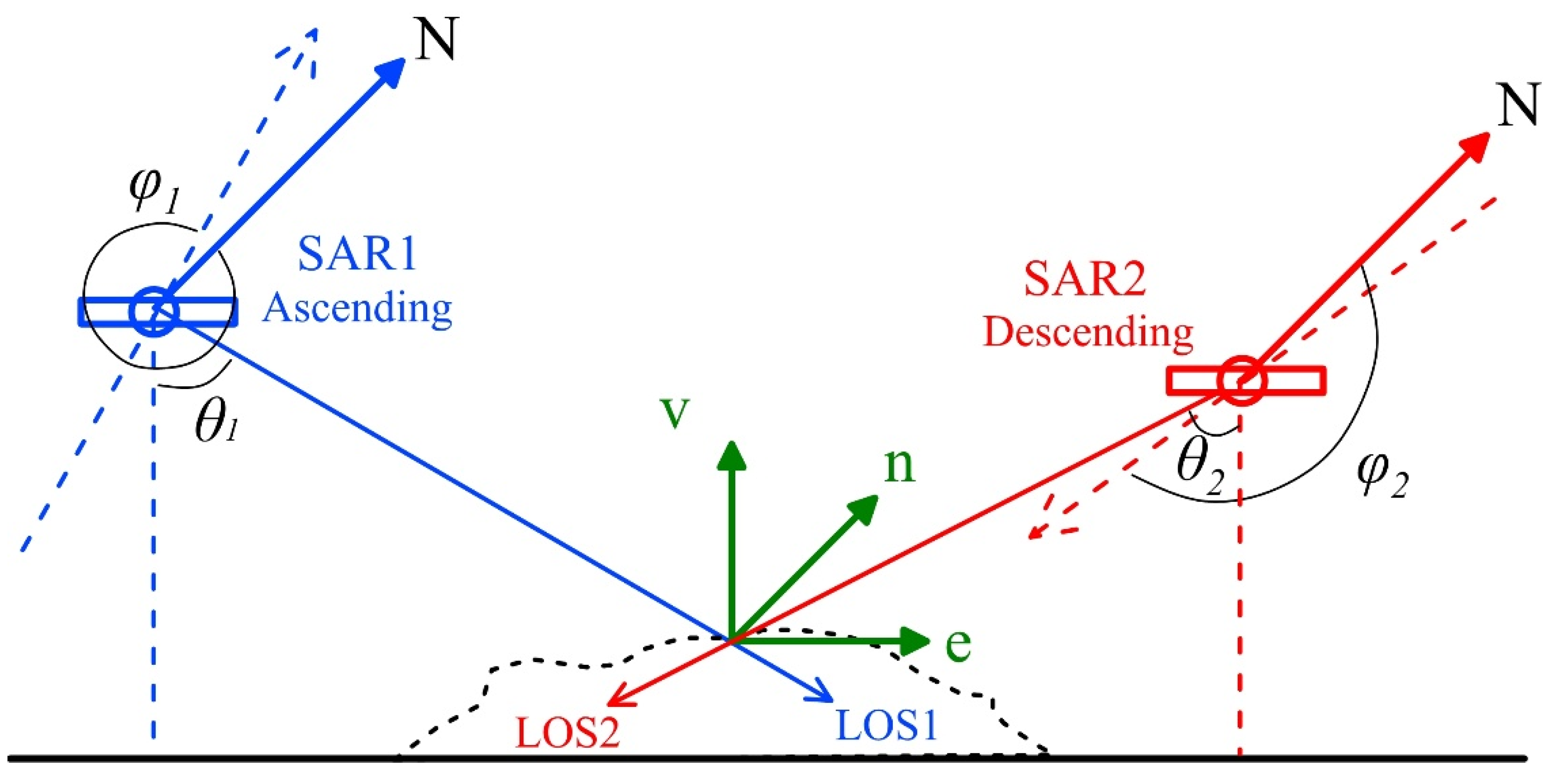
Figure 1 shows the satellite SAR imaging geometry along the ascending and descending orbits and the projection relation between the LOS displacement and the 3D motion components. For a ground target, the LOS displacement rate D can be represented as a function of the 3D motion rates and the SAR imaging angular parameters, i.e.,
D = d v cos θ d e cos φ sin θ + d n sin φ sin θ
where dv, de and dn are the vertical, east-west (E-W) and north-south (N-S) displacement rate at a target, respectively; θ is the radar incidence angle; φ is the azimuth angle (measured clockwise from the north) of the satellite flight direction along the ascending or descending orbit. According to Equation (9), the sensitivities of a SAR system to 3D motion components can be expressed by the partial derivatives, i.e.,
D d v = | cos θ | ,     D d e = | cos φ sin θ | ,      D d n = | sin φ sin θ |
As almost all the current SAR systems have a radar incidence angle of 20°–45° and the azimuth angle of 348°–352° for the ascending orbit or 188°–192° for the descending orbit, one can infer with Equation (10) that the sensitivities to dv, de and dn are 71%–94%, 33%–70% and 5%–15%, respectively. It is clear that the maximum sensitivity to motion detection is in the vertical direction, while the minimum sensitivity is in the N-S direction. If the three types of LOS displacement rates (i.e., DI, DII and DIII) can be derived through TCPInSAR processing with use of the multi-platform descending and ascending SAR images, the observation equation for solving dv, de and dn at a target can be expressed by
[ D I D I I D I I I ] = A [ d v d e d n ]
where
A = [ a I b I c I a I I b I I c I I a I I I b I I I c I I I ]
in which a i = cos θ i , b i = cos φ i sin θ i , c i = sin φ i sin θ i ( i = , ,   ).
Figure 1. The satellite SAR imaging geometry along the ascending and descending orbits and the projection relation between the LOS displacement and the 3D motion components. The dashed arrows denote the flight directions of the ascending and descending orbits.
Remotesensing 07 09542 g001
Albeit the sensitivities of a SAR system to de and dn are relatively low, they cannot be ignored during the reconstruction of 3D displacements. Before further processing, the three types of LOS displacement rates should be first geocoded and interpolated onto the same geographic grid points (e.g., in the UTM coordinate system). We then propose a localized LS method based on a moving window to solve the 3D displacement rates at the center of the window. It is acceptable to assume that the E-W and N-S motions would be same within a relatively small localized window (e.g., 1 km × 1 km) in the case that there are no special geological settings and hydrocarbon reservoirs in the study area. According to the observation of Equation (11), if the three different LOS displacement rates are available for each point, the 3D displacement rates at the center of the window can be estimated by an LS solution with the LOS displacement rates at all the points in the window. In an arbitrary localized window with n points, the observation equation can be expressed by:
B 3 n × ( n + 2 ) × X ( n + 2 ) × 1 = L 3 n × 1 + R 3 n × 1
in which the coefficient matrix B, the unknown vector X to be estimated, the observation vector L and the correction vector R can be denoted by:
B 3 n × ( n + 2 ) = [ a I     0        0     b I      c I 0      a I        0     b I      c I                            0      0        a I     b I      c I a I I     0        0     b I I     c I I 0      a I I        0     b I I     c I I                            0      0        a I I     b I I     c I I a I I I     0        0     b I I I     c I I I 0      a I I I        0     b I I I     c I I I                            0     0        a I I I      b I I I     c I I I ]
X ( n + 2 ) × 1 = [ d v 1 d v 2 d v n d e d n ]
L 3 n × 1 = [ D I 1 D I 2 D I n D I I 1 D I I 2 D I I n D I I I 1 D I I I 2 D I I I n ] T
R 3 n × 1 = [ r I 1 r I 2 r I n r I I 1 r I I 2 r I I n r I I I 1 r I I I 2 r I I I n ] T
It can be seen from Equation (15) that the n VDRs (i.e.,   d v i ,   i = 1 ,   2 ,   ,   n ) and the E–W and N–S displacement rates (i.e., de and dn) in the localized window are unknown parameters to be estimated. The unknown parameters can be solved by a LS method, i.e.,
X = ( B T PB ) 1 B T PL
where P is the weight matrix and we use a unit matrix here. The localized LS method can be performed on a point-by-point basis, thus resulting in the VDR and HDR at each point in the study area.

3. Study Area and Data Source

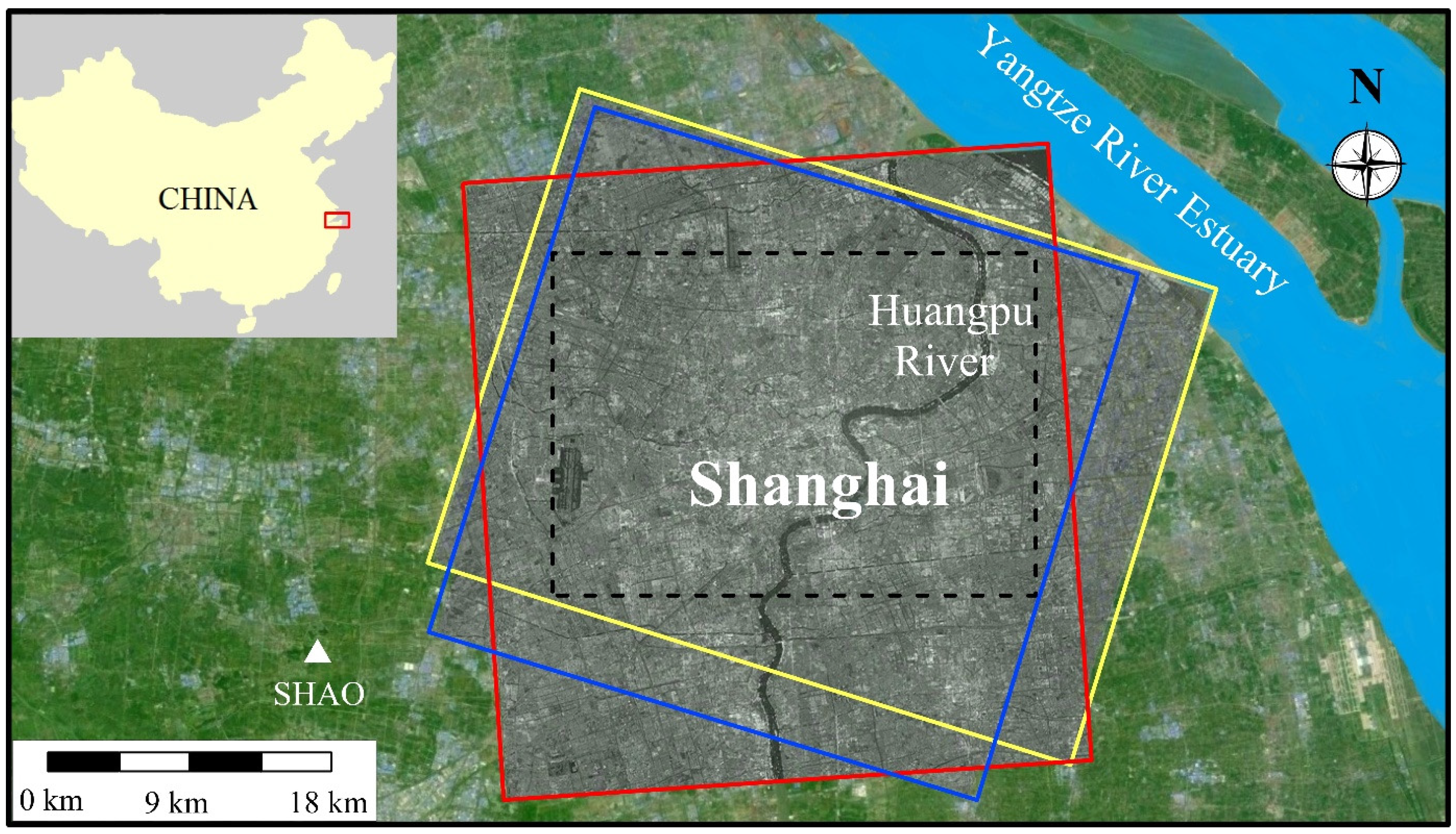
To extract the VDRs in Shanghai by the method presented in Section 2, we utilize high resolution SAR images, acquired along ascending/descending orbits in HH polarization by the X-band (i.e., λ = 3.1 cm) radar sensors onboard the CSK and TSX satellites. The data source used in this study includes 15 ascending CSK images, collected between 11 January 2009 and 12 April 2010, 15 descending CSK images, collected between 5 January 2009 and 30 April 2010, and 10 descending TSX images, collected between 28 March 2009 and 30 January 2010. Figure 2 shows the study area around Shanghai and the coverage of the three types of SAR images (i.e., the ascending/descending CSK images and the descending TSX images). The insert at the upper-left corner in Figure 2 depicts the location of Shanghai in China. The red, yellow, and blue rectangles marked in Figure 2 indicate the ascending CSK, descending CSK, and descending TSX coverage, respectively. The overlapping area (marked by the dashed black rectangle in Figure 2) of the three types of SAR images is selected as the study area (about 500 km2), consisting of the central downtown and suburbs of Shanghai. Table 1 lists the parameters related to the three types of SAR images, including the azimuth angles of the satellite-flight directions, the incidence angles of the radar sensors, and the pixel spacing in slant range and azimuth.
Figure 2. The study area around Shanghai and the coverage of the three types of SAR images. The insert depicts the location of Shanghai in China. The red, yellow, and blue rectangles indicate the ascending CSK, descending CSK, and descending TSX coverage, respectively. The dashed black rectangle indicates the study area, i.e., the overlapping area of the three types of SAR images. The filled white triangle denotes the ITRF2000 reference station SHAO.
Remotesensing 07 09542 g002
Table 1. The parameters related to the ascending/descending CSK and descending TSX SAR images.
CSK (Ascending)CSK (Descending)TSX (Descending)
Azimuth angle (degrees)350191190
Incidence angle (degrees)404026
Pixel spacing in slant range (m)1.21.0 0.9
Pixel spacing in azimuth (m)2.21.82.0
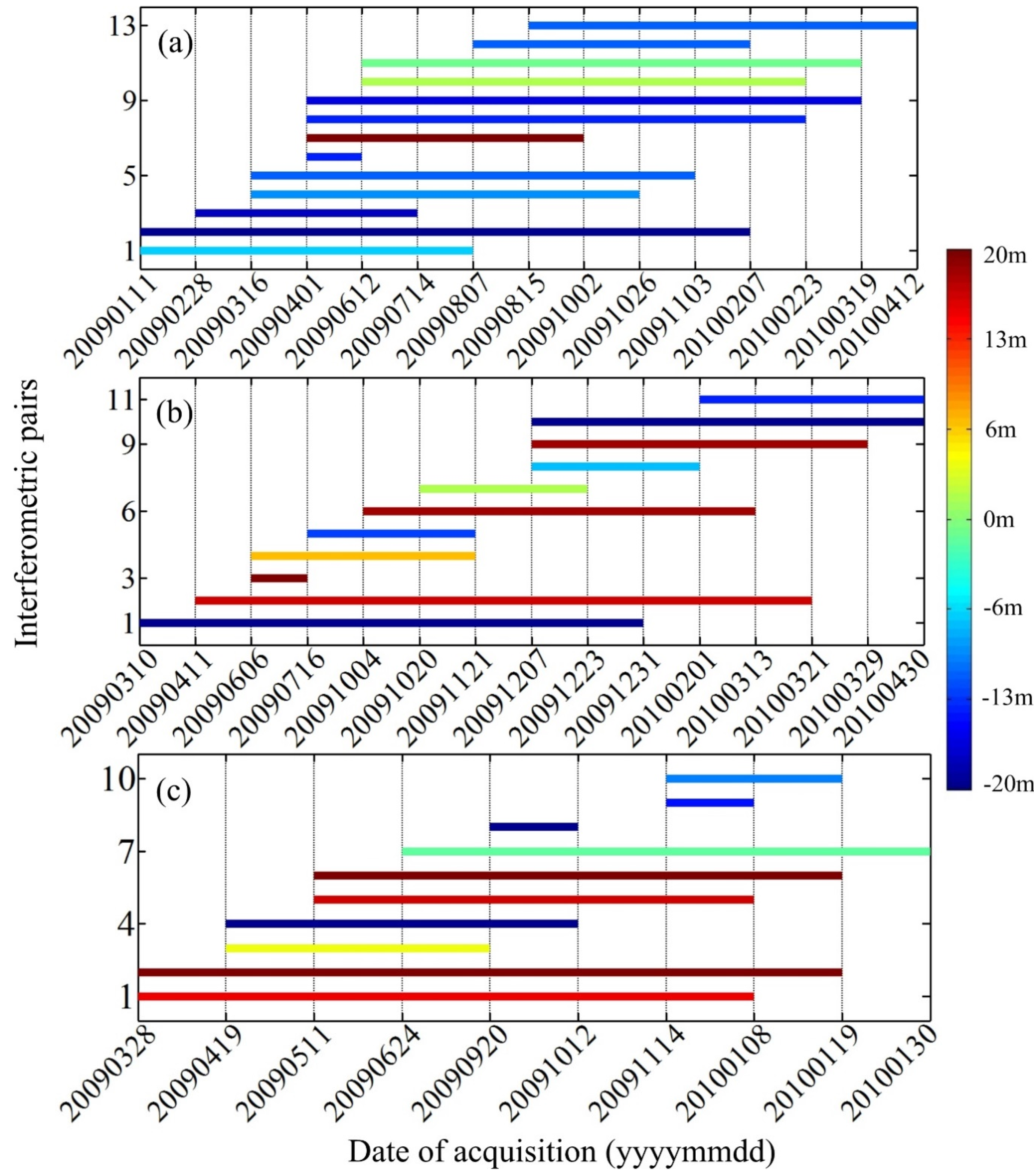
To generate the interferograms for extracting the VDRs, we selected the interferometric pairs with short spatial baselines according to the given threshold. For the cases of ascending CSK and descending TSX, the interferometric pairs with spatial baselines of less than 15 m were chosen for further data reduction. For the case of descending CSK, the baseline threshold of 20 m was used to select the interferometric pairs, thus increasing the total number of interferograms to 11. Figure 3 shows the spatial and temporal baselines of the interferometric pairs identified for the cases of ascending CSK, descending CSK, and descending TSX, respectively. The color bar indicates the spatial baseline length of each interferometric pair, and the horizontal line indicates the temporal baseline (i.e., time interval) for the corresponding interferometric pair. It can be seen that there are 13, 11, and 10 interferometric pairs available for the cases of ascending CSK, descending CSK, and descending TSX, respectively. As the short spatial baseline pairs are less sensitive to topographic effects and high-rise buildings, we carried out the differential processing for all the pairs, as shown in Figure 3, without using an external DEM.
Figure 3. The spatial and temporal baselines of the interferometric pairs selected for the cases of (a) ascending CSK; (b) descending CSK; and (c) descending TSX, respectively. The color bar indicates the spatial baseline length of each interferometric pair, and the horizontal line indicates the temporal baseline (i.e., time interval) for the corresponding interferometric pair.
Remotesensing 07 09542 g003

4. Results and Discussion

4.1. The VDRs Derived by TCPInSAR

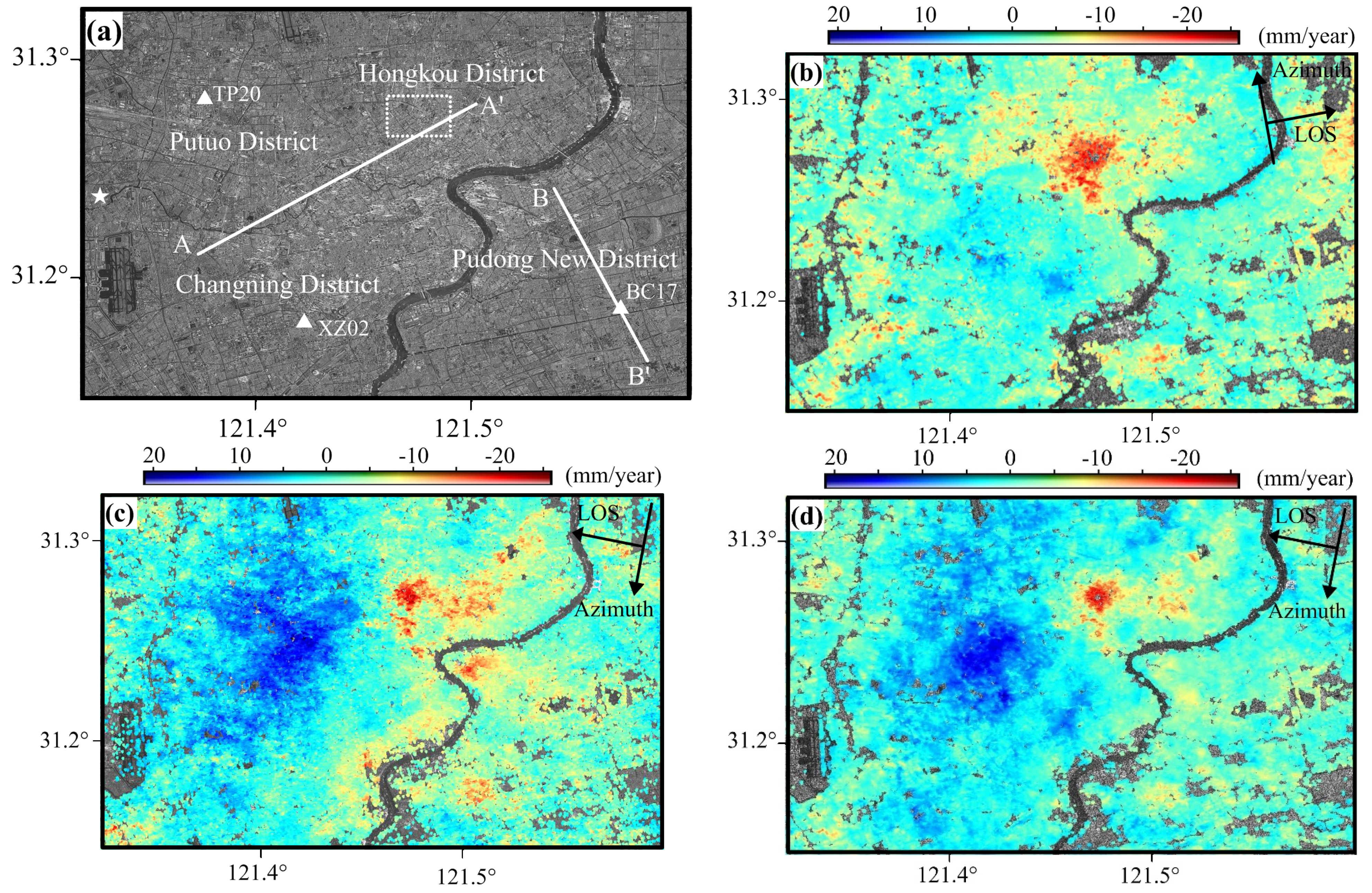
The LOS displacement rates at all the TCPs were first estimated using 13, 11, and 10 interferometric pairs for the three cases of ascending CSK, descending CSK, and descending TSX, respectively, by following the method described in Section 2.1, thus deriving three types of LOS displacement rates for the study area. The VDRs at the TCPs were then calculated by dividing the LOS displacement rates by the cosine of the radar incidence angle. Figure 4 shows the SAR amplitude image and the resultant VDRs in the study area derived through the TCPInSAR processing for the three cases of SAR images, exhibiting the similar distribution of VDRs. Figure 4a shows the SAR amplitude image with annotation of the place names (i.e., Hongkou District, Putuo District, Pudong District, and Changning District), three GPS sites (i.e., TP20, XZ20, and BC17), the reference point for interferometric processing (indicated by a white star), a dashed rectangle, and two reference lines, which are used for later analysis. It should be noted that the VDRs are estimated using the reference point with zero motion. Figure 4b–d show the VDRs derived for the three cases of ascending CSK, descending CSK, and descending TSX, respectively.
It can be observed from Figure 4b–d that the VDRs range between −24 and 10, −26 and 23, and −27 and 22 mm/year for the ascending CSK, descending CSK, and descending TSX cases, respectively. The VDRs derived from the two types of descending datasets are in better agreement. A subsiding bowl appears around the Hongkou District, which will be further analyzed in Section 4.3. A tendency of land uplifting appears in the middle of the maps, which is most likely ascribed to the efforts of groundwater recharge implemented by the Shanghai municipal government. Such results are in good agreement with those reported in previous studies [12,13,25], thus indicating that the TCPInSAR method is viable for detecting land displacements around the urban and suburban areas without using an external DEM.
As a remark, it can be seen from Figure 4b–d that the density of TCPs in the study area is very high for the three cases of SAR images. The statistical calculation shows that the density of TCPs reaches up to 3800, 4800, and 4900 per square kilometer for the ascending CSK, descending CSK, and descending TSX cases, respectively. The similar density of TCPs can be observed for the descending CSK and TSX cases, while the density of TCPs for the descending cases are about 1000 per square kilometer more than that for the ascending CSK case. This means that the different radar look directions play an important role for the density of TCPs in the study area with a number of high-rise buildings, but the different radar sensors have no apparent impact on the density of TCPs.
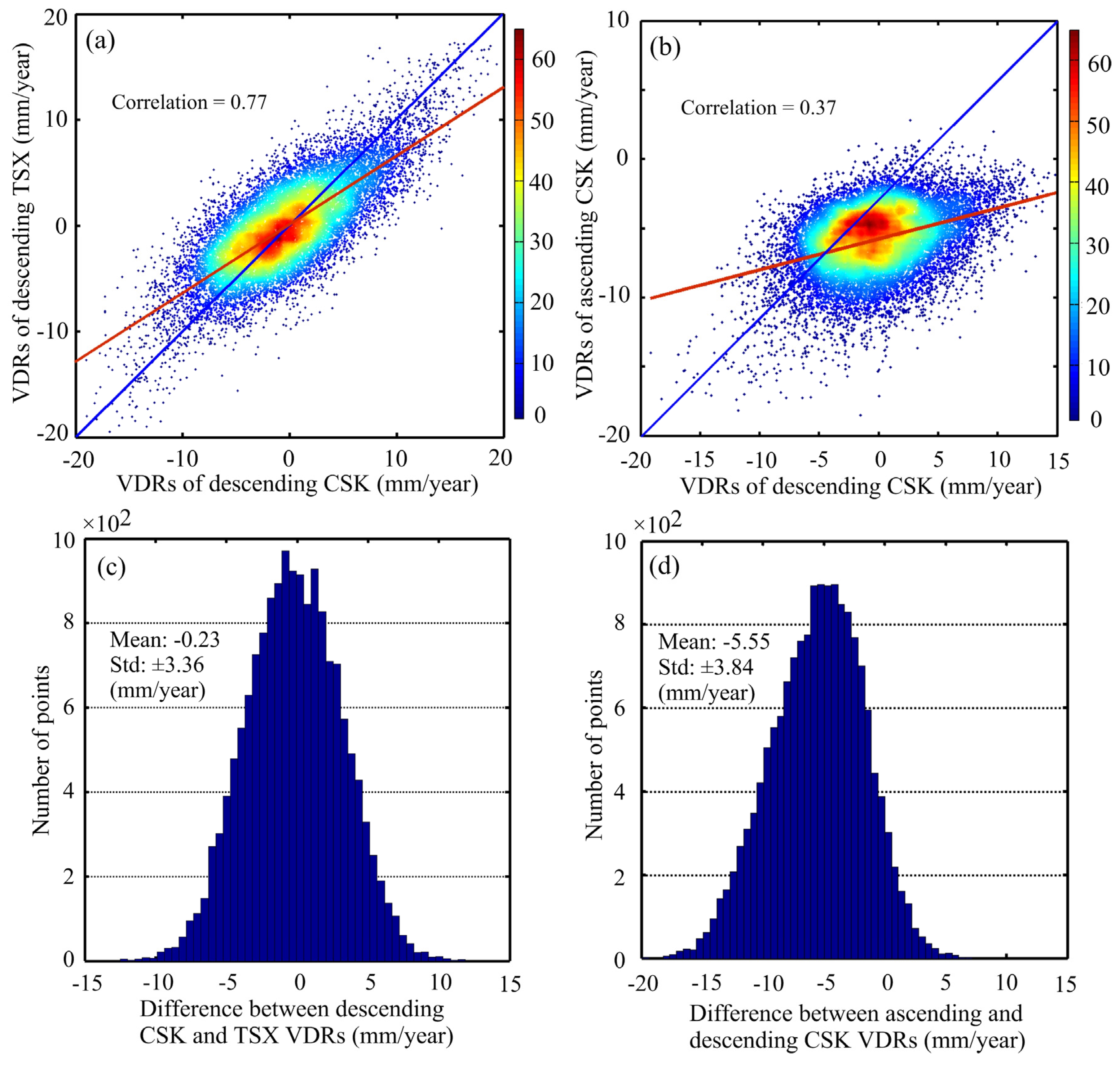
To further analyze the impacts of both the radar sensor and radar look direction on the VDRs, a comparison was performed between the VDRs derived from the descending CSK and descending TSX images, while the VDRs derived from the ascending and descending CSK images are mutually compared. The former comparison intends to reflect the discrepancy associated with the different radar sensor and the same-side radar look direction, while the latter comparison aims to reflect the discrepancy associated with the same radar sensor and the opposite radar look direction. Figure 5 shows the two comparison cases. Figure 5a,c show the correlation map and the difference histogram of the descending CSK against descending TSX VDRs, while Figure 5b,d show the comparisons of the ascending against descending CSK VDRs.
The statistical calculation indicates that the mean and standard deviation of the differences between the descending CSK and TSX VDRs are −0.2 mm and ±3.4 mm/year, respectively, while those between the ascending and descending CSK VDRs are −5.6 mm and ±3.8 mm/year, respectively. The correlation coefficient between the descending CSK and TSX VDRs is 0.77, while that between the ascending and descending CSK VDRs is 0.37. It is clear that the VDRs derived from the same-side radar look directions are in obviously better agreement than those derived from the opposite radar look directions, although the different radar incidence angles also have an impact on the VDRs.
Figure 4. The SAR amplitude image and the VDRs in the study area derived through the TCPInSAR processing. (a) shows the SAR amplitude image with annotation of the placenames (Hongkou District, Pudong New District, Putuo District, and Changning District), three GPS sites (TP20, XZ20, and BC17), the reference point for interferometric processing (indicated by a white star), a dashed rectangle and two reference lines, which are used for later analysis. The VDRs are shown in (bd) for the ascending CSK, descending CSK, and descending TSX case, respectively.
Remotesensing 07 09542 g004
It should be realized that the validity of the simple conversion from the LOS to vertical displacement at a ground target can be guaranteed if and only if no horizontal motion takes place. Previous studies indicate that the study area is actually affected by the horizontal crustal movements due to the specific geological settings [26,27]. According to the global positing system (GPS) measurements derived from the China Crustal Movement Observation Network, the mean velocity of horizontal motion in the coastal region of Eastern China is about 20 mm/year towards southeast, and the uneven horizontal motions can be observed in the region [26]. Moreover, the GPS results derived at the ITRF2000 reference station SHAO (see Figure 2) in Shanghai indicate that its eastward and northward velocity is 32 and 16 mm/year, respectively. It means that the land around Shanghai is moving east-southeastward with respect to the stable Eurasia [27]. Further analysis with the GPS data at other sites shows that the velocity of horizontal motion varies spatially in the study area of Shanghai (see Section 4.2). The aforementioned comparisons show that the radar look directions (i.e., same-side and opposite) have a significant impact on the results of VDRs. If no uneven horizontal motion occurs in the study area, the VDRs derived from the three cases of SAR images should be in very good agreement. It can be concluded that the uneven horizontal motion in the study area cannot be ignored and the VDRs shown in Figure 4 should be further improved.
Figure 5. The comparison between the VDRs derived from the different cases of SAR images (ad). (a,c) show the scatterplot and the difference histogram, respectively, of the descending CSK against descending TSX VDRs, while (b,d) show the comparisons of the ascending against descending CSK VDRs. The red lines and the colorbar in (a,b) are the best-fit lines and the frequency number of VDRs.
Remotesensing 07 09542 g005

4.2. The Improved VDRs and Cross Validation

We further improved the VDRs by following the localized LS solution method as presented in Section 2.2. The LOS displacement rates were first extracted for the study area (marked in Figure 2) for the ascending CSK, descending CSK, and descending TSX case, respectively, thus deriving the three types of LOS displacement rates at the same grid points as the input of the localized LS solution. For the convenience of further processing, the Kriging interpolation [28] was first performed at all the grid points with missing data for each type of LOS displacement rates. Considering the angular parameters listed in Table 1, the transform Equation (11) for the LS solution can be rewritten by:
[ D I D I I D I I I ] = [ 0.766 0.632 0.116 0.766 0.630 0.125 0.896 0.437 0.083 ] [ d ν d e d n ]
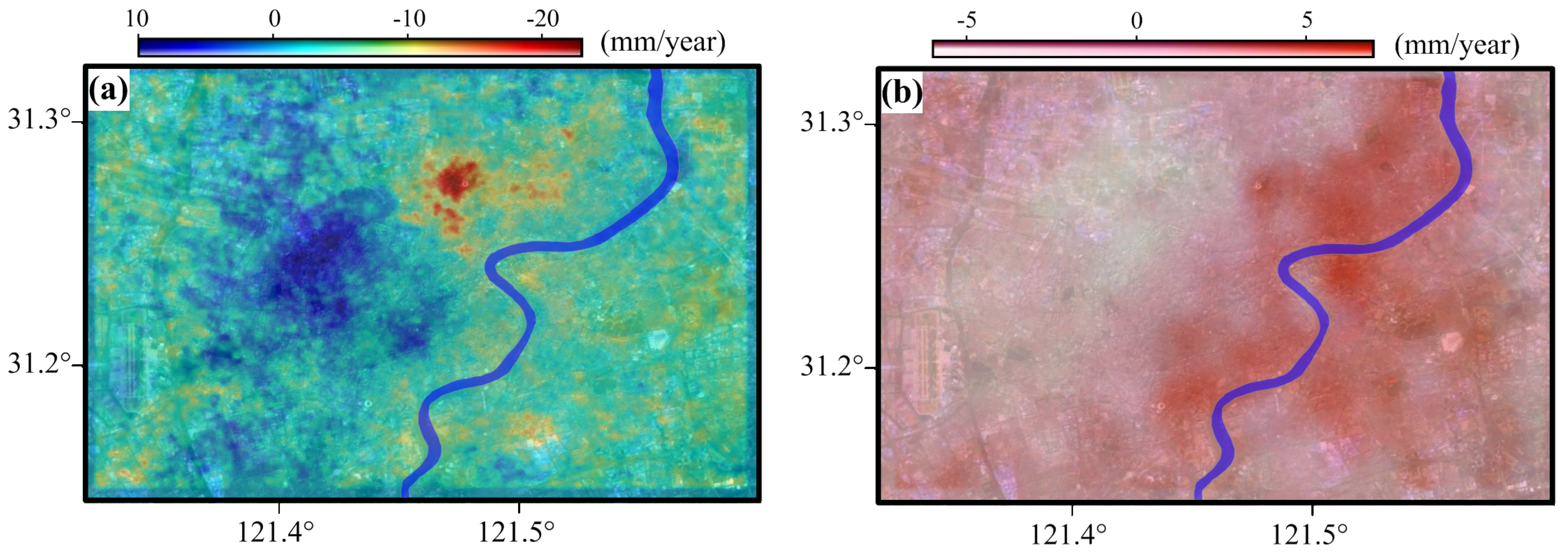
The localized LS method (see Section 2.2) based on a moving window with a size of about 1.5 km ×1.5 km was then applied to estimate the improved VDRs and HDRs on a point-by-point basis. The VDRs and HDRs at the center point of the window were resolved by the LS solution with use of the three types of LOS displacement rates in the window. Figure 6a shows the distribution of the resultant VDRs in the study area derived by the localized LS method based on the multi-platform SAR images. It can be observed from Figure 6a that the improved VDRs range between −23 and 10 mm/year in the study area.
Figure 6. The maps of the resultant VDRs (a) and the relative E–W displacement rates (b) in the study area derived by the localized LS method based on the multi-platform SAR images.
Remotesensing 07 09542 g006
As a by-product, Figure 6b shows the map of E-W displacement rates in the study area with reference to the GPS site XZ02 (see Figure 4a). As the relative N-S motion magnitude is smaller in the study area (also indicating by the GPS results at the ITRF2000 reference station SHAO) and that InSAR is not very sensitive to the N-S motion, the relative N-S displacement rates are not presented here. It can be seen from Figure 6b that the relative E-W displacement rates range between −7.2 and 6.2 mm/year. The pattern in Figure 6b indicates that E-W motion is not consistent in the entire study area. The magnitude of E-W displacement rates in the left part of the study area is smaller than that in the right part. The relative E-W displacement rates derived by our study at the GPS sites TP20 and BC17 (see Figure 4a) are −1.8 and 2.9 mm/year, respectively, which are comparable with those (−2.2 and 4.4 mm/year) derived from the GPS measurements by Cai et al. [27]. Obviously, such numerical comparison shows that uneven horizontal motions have taken place in the study area, although the GPS results were derived in advance (about four years) than the InSAR results. This also indicates that our localized LS method based on the multi-platform SAR images can be applied to efficiently improve the VDRs in the study area.
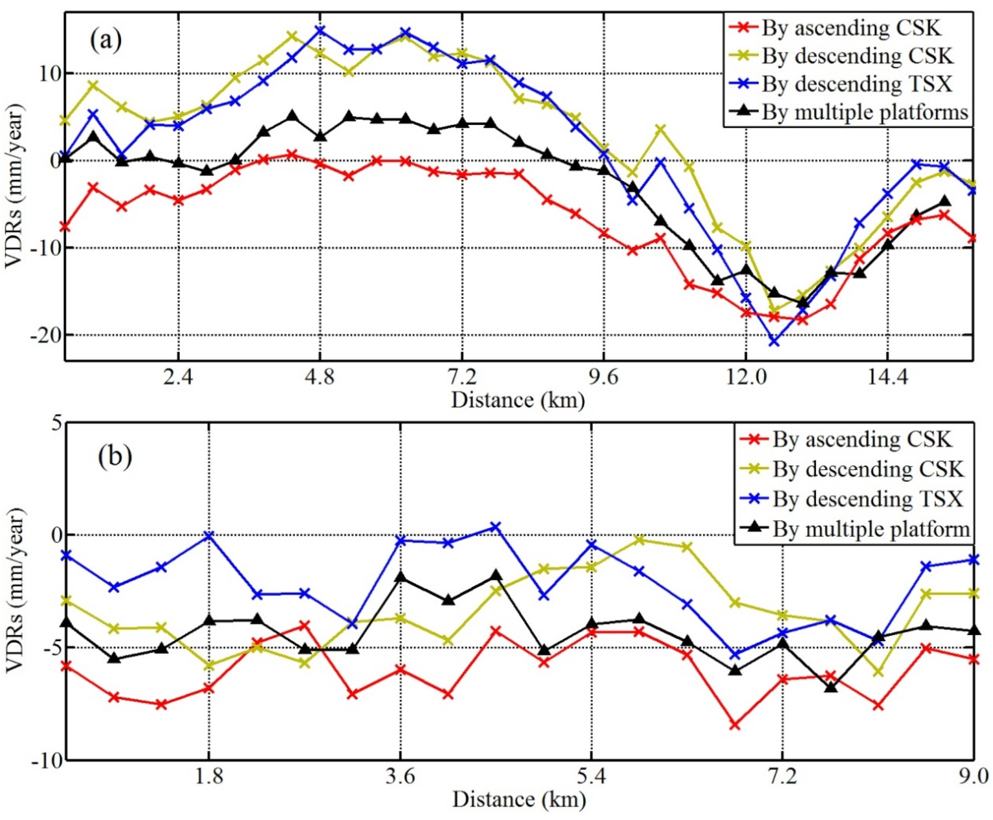
Figure 7. The comparisons of the profiles of VDRs derived from processing of the single- and multi-platform SAR images along the lines AA′ (a); and BB′ (b).
Remotesensing 07 09542 g007
To compare the VDRs derived from the single- and multi-platform SAR images, Figure 7 shows the examples of two profiles of VDRs extracted along the lines AA′ and BB′ (see Figure 4a) from the results as shown in Figure 4b–d and Figure 6. It is clear that the variation trend of VDRs along either AA′ or BB′ is very similar among the four types of results derived from the multi-platform, ascending CSK, descending CSK and descending TSX data. The four types of VDRs along AA′ across the subsiding bowl around the Hongkou District and the Changning District range between −20 and 13 mm/year, while those along BB′ across the Pudong New District range between −7 and 2 mm/year. However, the profile of VDRs derived from the multi-platform data is located in the middle of the profiles of VDRs derived from the three types of single-platform data.
It should be noted that the profile of VDRs along either AA′ or BB′ derived from the descending CSK data is generally closer to that derived from the descending TSX data, while the profile derived from the ascending CSK data is apparently not consistent with those derived from the descending CSK and TSX data. Such discrepancy can be ascribed to the uneven eastward horizontal motion in the study area, which may result in the biased VDR (see Figure 1). In the ascending case, the eastward motion can cancel out a portion of uplifting magnitude in the uplifting area (see the left section of Figure 7a) and provide the additional but erroneous subsiding magnitude in the subsiding area (Figure 7b), thus resulting in the smaller and larger vertical displacement magnitude (biased), respectively. In the descending case, the eastward motion can provide the additional but erroneous uplifting magnitude in the uplifting area and cancel out a portion of subsiding magnitude in the subsiding area, thus resulting in the larger and smaller vertical displacement magnitude (biased), respectively. This indicates once again that the horizontal motion in the study area cannot be ignored, and the simple method of converting from the LOS to vertical displacement cannot be accepted for a study area with even minor horizontal motion. It can be concluded that the VDRs derived by the TCPInSAR-LS solution with the multi-platform data are more accurate than those derived only by the TCPInSAR solution with the single-platform data.

4.3. Analysis and Discussion

The existing studies indicated that the groundwater pumping and the high-rise buildings are the two main reasons for land sinking in shanghai [29,30]. Xu et al. [31] reported that the Quaternary deposit of about 300 m in Shanghai is composed of an alternated multi-aquifer-aquitard system, and the groundwater system is composed of the five aquifer layers and the five aquitard layers. Most areas of Shanghai are covered by loose and soft soil, thus leading to plenty of groundwater resource. With the rapid urban expansion in Shanghai, the groundwater pumping cannot be stopped completely in some localized areas, thus still resulting in land subsidence, although the Shanghai municipal government has taken some control measures to mitigate land subsidence, for example, reducing groundwater extraction and increasing groundwater recharge. Due to the groundwater pumping and the overload related to the high-rise buildings in Shanghai, the water releases from the pores in soil and the valid pressure becomes larger [30], thus leading to decline of the groundwater level, compression of the loose soil and land sinking.
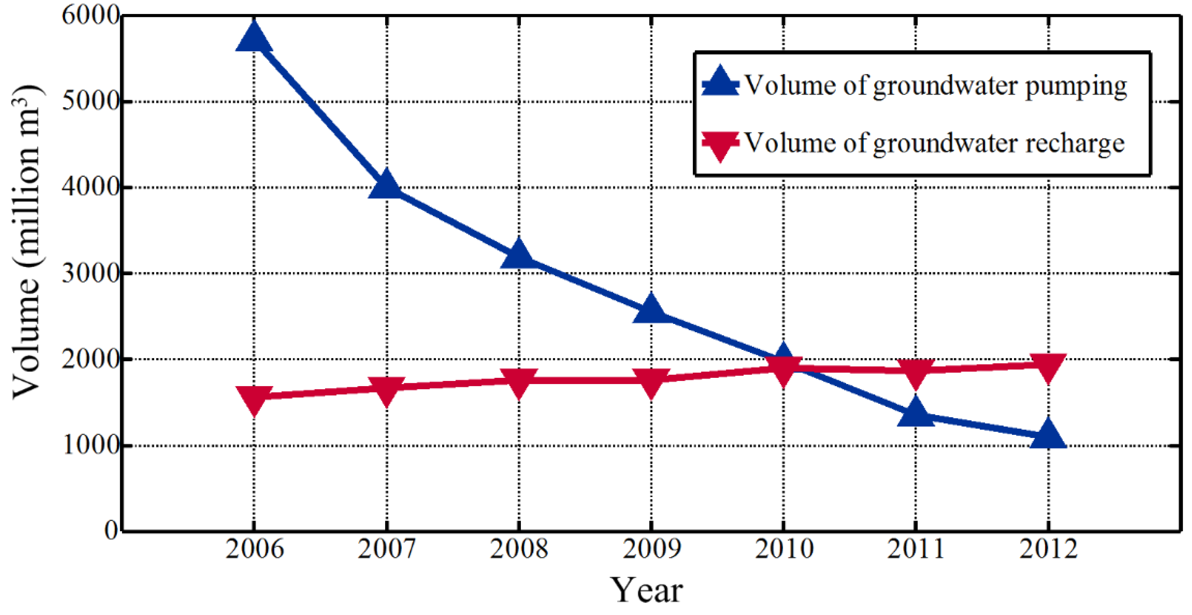
Figure 6a exhibits that the Pudong New District in Shanghai (the right-hand side in Figure 6a) is of a relatively stable region with a minor sinking or uplifting trend, which is a newly-developed district (establishing since 1995) with a long-term ecological development strategy. However, a subsiding bowl appears in the Hongkou District, and will be further analyzed later. Moreover, a large uplifting part with an area of about 70 km2 appears in the west downtown of Shanghai, i.e., at the south of the Putuo District and the north of the Changning District. Such an uplifting trend can be ascribed to the two control measures implemented by the Shanghai municipal government, i.e., decreasing the groundwater pumping volume and increasing the groundwater recharge volume. According to the Shanghai Water Resource Bulletin [32], Figure 8 shows the total volume of groundwater pumping and recharge fulfilled in Shanghai for every year in the period of 2006–2012. It can be seen that the volume of groundwater pumping and recharge in Shanghai was dramatically decreased and gradually increased, respectively, in the six years. In 2010, the volume of groundwater pumping and recharge almost reached to the same magnitude (about 2000 million·m3). Before 2010, the volume of groundwater pumping was larger than the volume of groundwater recharge. After 2010, the volume of groundwater recharge started to exceed the volume of groundwater pumping. Such data analysis can reasonably explain the land uplifting trend at the west downtown of Shanghai and the land stableness in the Pudong New District.
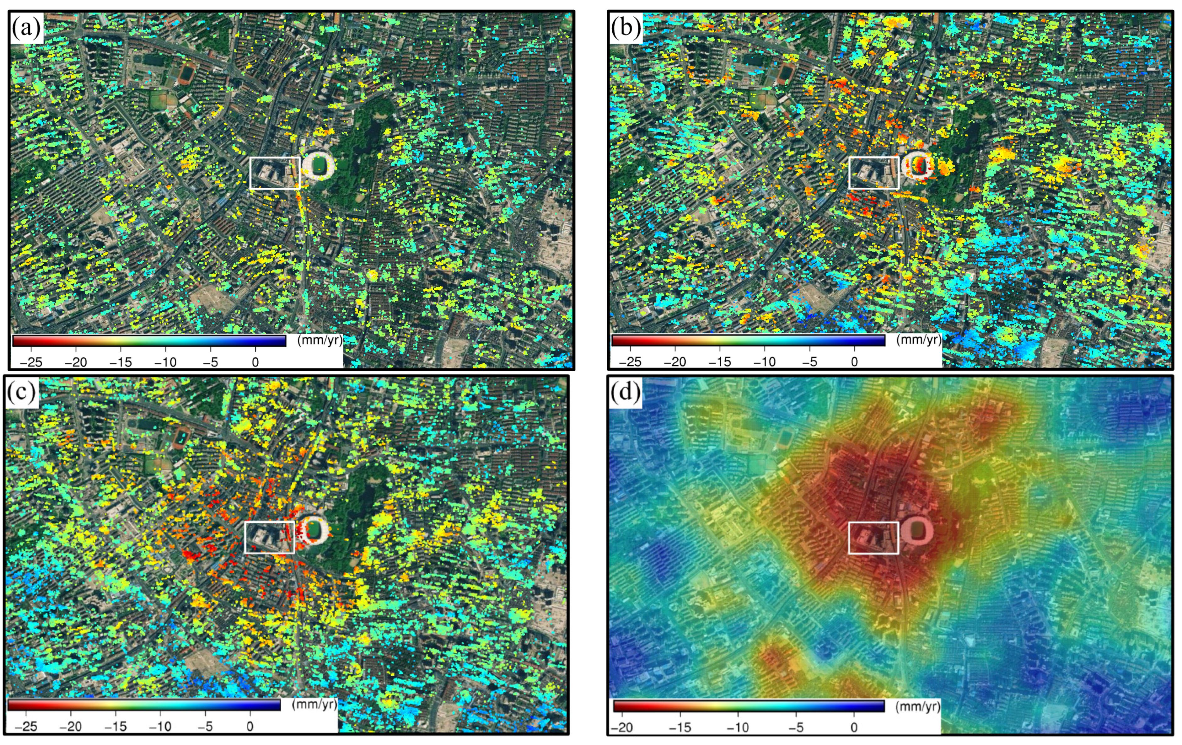
The further analysis concentrates on an area of about 3 km2 (marked by a dashed rectangle in Figure 4a) located in the Hongkou District, which is identified as a subsiding bowl. Figure 9 displays the enlarged maps of VDRs (superimposed onto the high-resolution optical image obtained from Google Earth) around the subsiding bowl derived from the single- and multi-platform SAR images. Figure 9a–c show the maps of VDRs at all the TCPs derived through the TCPInSAR processing for the three cases of single-platform SAR images acquired by the ascending CSK, descending CSK, and descending TSX, respectively. Figure 9d shows the map of improved VDRs derived through the localized LS method based on the multi-platform SAR images. It can be seen that from Figure 9a–d, land subsidence has taken place in the localized area. The VDRs obtained from the single-platform SAR images range between −24 and 1, −26 and 4, and −27 and 3 mm/year for the ascending CSK, descending CSK, and descending TSX case, respectively, while the VDRs obtained from the multi-platform SAR images range between −23 and 0 mm/year.
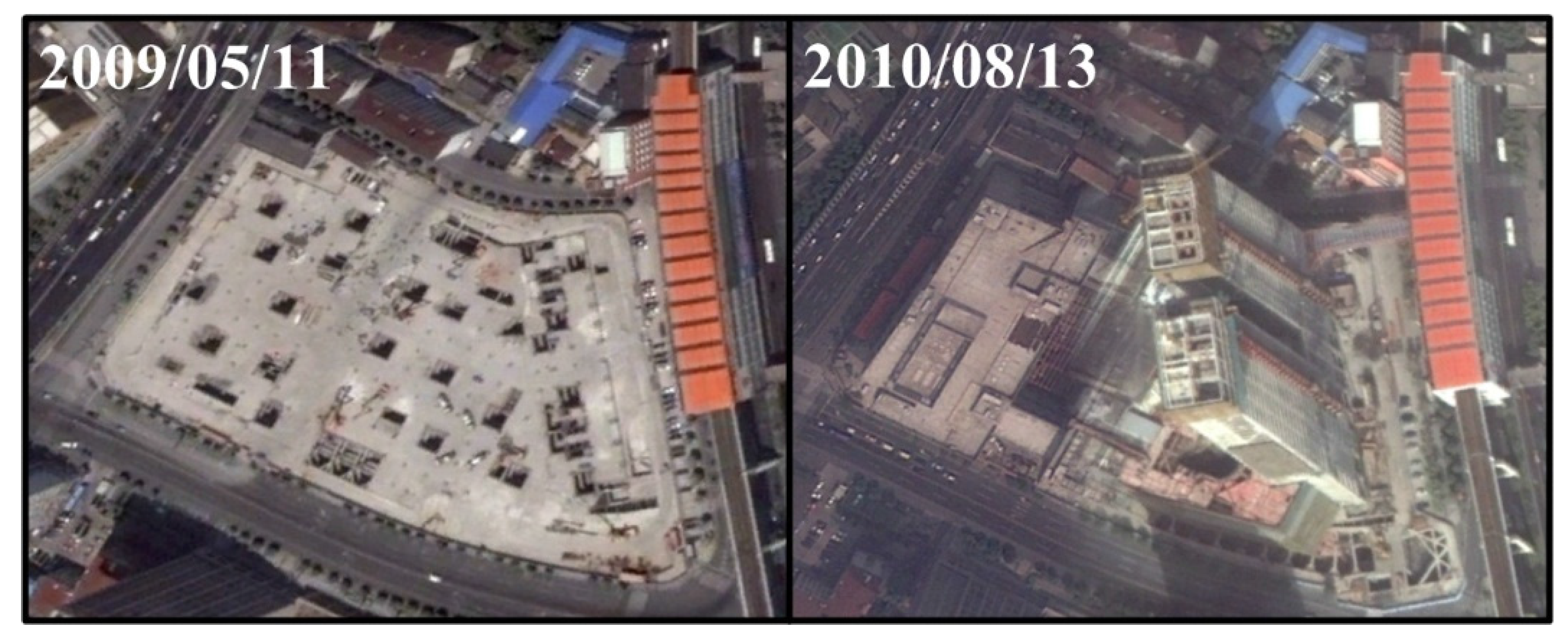
A careful inspection with Figure 9a–c indicates that the TCPs are primarily distributed over the roofs of buildings and the subsiding bowl center corresponds to the Hongkou Stadium of Shanghai. It is very interesting that the localized part (marked by a rectangle in Figure 9) around the subsiding bowl center possess the sparse TCPs, thus indicating that the temporal radar decorrelation occurred in this part. According to our detailed investigation, this part was under construction during the acquisition of CSK and TSX images used in this study. This can be verified by the two enlarged optical image patches as shown in Figure 10, which were acquired on 11 March 2009 and 12 August 2010, respectively. It shows that the building construction was ongoing. The TCPs were therefore sparse in this part due to the temporal radar decorrelation associated with the surface alteration. As few TCPs are available around the subsiding bowl, the VDRs obtained by interpolation in the localized area have limited reliability and accuracy.
Figure 8. The groundwater pumping and recharge volume fulfilled in Shanghai for every year in the period of 2006–2012. The data are obtained from the Shanghai Water Resource Bulletin [32].
Remotesensing 07 09542 g008
Figure 9. The enlarged maps of VDRs around the subsiding bowl derived from the single- and multi-platform SAR images, which are superimposed onto the high-resolution optical image obtained from Google Earth. (ac) show the maps of VDRs at all the TCPs derived through the TCPInSAR processing for the three cases of single-platform SAR images acquired by the ascending CSK, descending CSK, and descending TSX, respectively; (d) shows the map of improved VDRs derived through the localized LS method with use of the multi-platform SAR images.
Remotesensing 07 09542 g009
Figure 10. The two high-resolution optical image patches acquired on 11 May 2009 and 13 August 2010, respectively, over the area indicated by the rectangle in Figure 9. The image patches are obtained from Google Earth.
Remotesensing 07 09542 g010
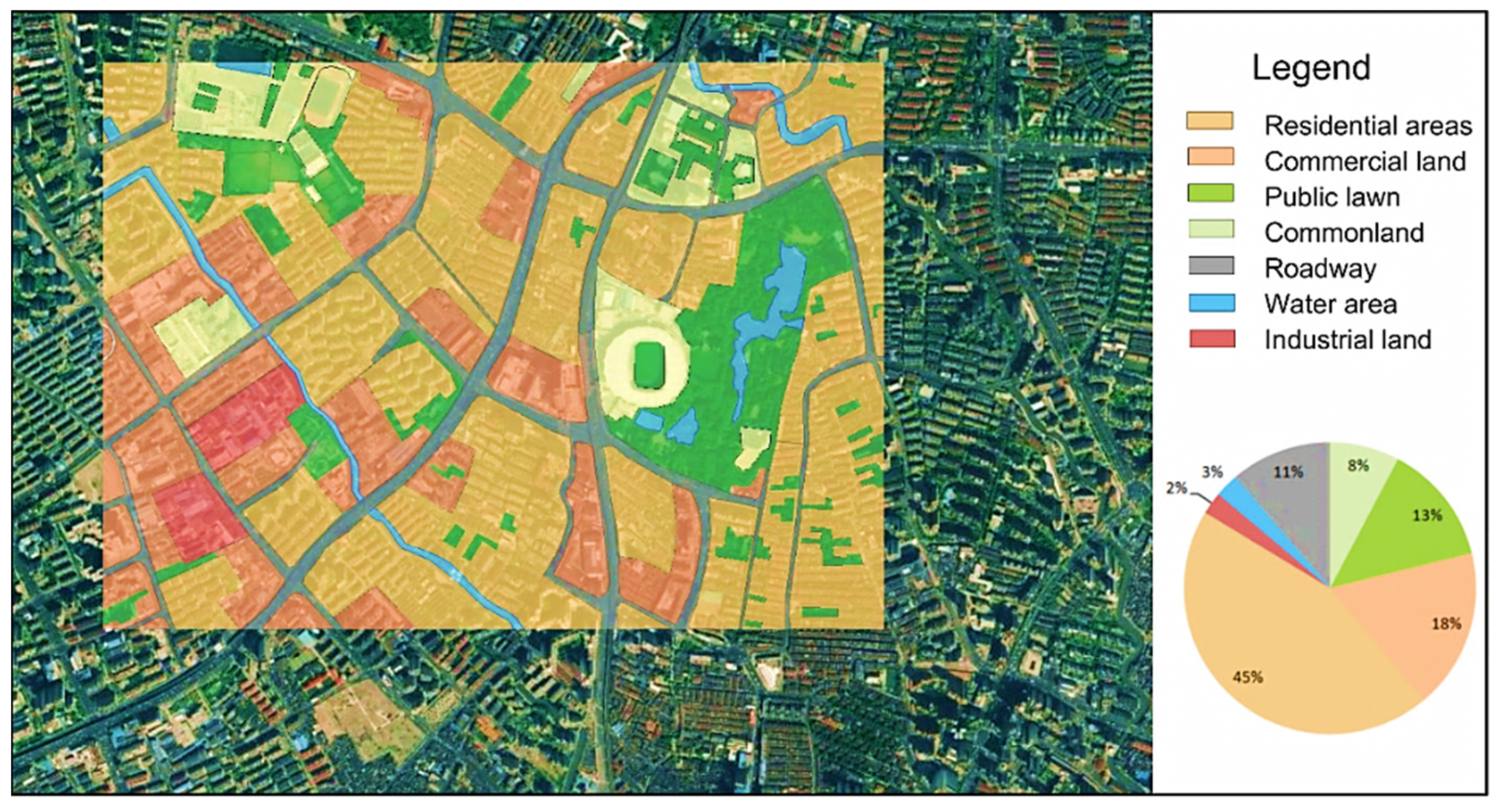
To explore the impact factors, we generated a map (see Figure 11) of land use classification in an area of 3.5 km2 around the subsiding bowl based on the optical image and the field investigation. The numerical calculation on the areas occupied by the different types of objects indicates that the residential and commercial parts accounts for 63%, the public lawn (Luxun Park) for 13%, and the industrial land for 2%. According to Wei et al. [33], the land subsidence is highly related to the building space ratio (BSR, i.e., a ratio between the total-building area and the land use area). If the BSR is bigger than 1.5, the land subsidence rate is usually higher than 20 mm/year [33]. The area as shown in Figure 11 has a high BSR (63% for residential and commercial land use in total). Apart from the factor of groundwater extraction, the dense population and the building overload may cause the land sinking. This implies that the BSR should be actually taken into account in the future urban planning in Shanghai.
Figure 11. The map of land use classification in an area of 3.5 km2 around the subsiding bowl.
Remotesensing 07 09542 g011

5. Conclusions

This paper presents the method for extracting the VDRS in the study area of Shanghai through the TCPInSAR processing and the localized LS solution based on the multi-platform high resolution SAR images. We first estimated the three types of LOS displacement rates by TCPInSAR with use of the ascending/descending CSK and descending TSX SAR images. The VDRs were then estimated through the localized LS method by utilizing the three types of LOS displacement rates derived by TCPInSAR. The resultant VDRs obtained from the multi-platform SAR data were analyzed by correlating with groundwater pumping/recharge data. For comparison purposes, the VDRs for the single-platform SAR data, i.e., for the three cases of ascending CSK, descending CSK and descending TSX SAR images, respectively, were also obtained through dividing the LOS displacement rates by the cosine of the radar incidence angle.
The VDRs obtained by TCPInSAR from the single-platform SAR data range between −24 and 10, −26 and 23, and −27 and 22 mm/year for the three cases of ascending CSK, descending CSK, and descending TSX, respectively. The statistical analysis indicates that the mean and standard deviation of the differences between the descending CSK and TSX VDRs are −0.2 and ±3.4 mm/year, respectively, while those between the ascending and descending CSK VDRs are −5.6 and ±3.8 mm/year, respectively. The correlation coefficient between the descending CSK and TSX VDRs is 0.77, while that between the ascending and descending CSK VDRs is 0.37. The VDRs derived from the same-side radar look directions are in obviously better agreement than those derived from the opposite radar look directions. The analysis with aid of the GPS measurements shows that the horizontal motion due to the geological settings cannot be ignored in Shanghai, thus indicating that the VDRs obtained from the single-platform SAR images are not accurate and reliable without taking into account the horizontal motion.
The results derived by the TCPInSAR-LS solution from the multi-platform SAR data reveals that the VDRs in the study area range between −22.8 and 9.6 mm/year, while the east-west motion rates range between −7.2 and 6.2 mm/year, and the north–south motion is subtle and can be ignored. The validation indicates that the accuracies in the VDRs derived by the proposed method can be efficiently improved due to integrating the multi-platform SAR data and considering both horizontal and vertical motion, thus overcoming the disadvantages in the conventional approach. The analysis on the improved VDRs show that an uplifting area of about 70 km2 appears at the west downtown of Shanghai, and a subsiding bowl appears in the Hongkou District of Shanghai. The correlation analysis shows that the uplifting trend can be ascribed to the two measures implemented by the Shanghai municipal government, i.e., decreasing the groundwater pumping volume and increasing the groundwater recharge volume.

Acknowledgments

This work was jointly supported by the National Basic Research Program of China (973 Program) under Grant 2012CB719901, the National Natural Science Foundation of China under Grant 41474003, and the Program for Changjiang Scholars and Innovative Research Team in University. We thank Tao Li from the GNSS Research Center, Wuhan University for providing the descending CSK images. Some figures in this paper were plotted using the Generic Mapping Tools (Wessel and Smith, 1998).

Author Contributions

Keren Dai performed data processing and analysis for this study and prepared the manuscript. Guoxiang Liu provided important guidance during preparation of this manuscript and repeatedly modified the manuscript. Zhenhong Li proposed the localized least squares method for improving estimation of the vertical displacement rates. Tao Li, Bing Yu and Xiaowen Wang provided useful suggestion on data processing and performed part of validation work. Andrew Singleton contributed to part of data analysis and proofreading of the manuscript.

Conflicts of Interest

The authors declare no conflict of interest.

References

  1. Liu, Y.; Zhang, X.; Wan, G.; Han, Q. The situation of land subsidence and countermeasures in Shanghai in recent years. Chin. J. Geol. Hazard Control 1998, 9, 13–17. [Google Scholar]
  2. Liu, Y. Preventive measures for Shanghai land subsidence and their effects (China). Volcanol. Miner. Resour. 2000, 21, 107–111. [Google Scholar]
  3. Shanghai Puts up a Fight to Stop Sinking. Available online: http://www.chinadaily.com.cn/en/doc/2003-07/16/content_245660.htm (accessed on 24 March 2015).
  4. Ferretti, A.; Prati, C.; Rocca, F. Permanent scatterers in SAR interferometry. IEEE Trans. Geosci. Remote Sens. 2001, 39, 8–20. [Google Scholar] [CrossRef]
  5. Berardino, P.; Fornaro, G.; Lanari, R.; Sansosti, E. A new algorithm for surface deformation monitoring based on small baseline differential SAR interferograms. IEEE Trans. Geosci. Remote Sens. 2002, 40, 2375–2383. [Google Scholar] [CrossRef]
  6. Lanari, R.; Mora, O.; Manunta, M.; Mallorquí, J.J.; Berardino, P.; Sansosti, E. A small-baseline approach for investigating deformations on full-resolution differential SAR interferograms. IEEE Trans. Geosci. Remote Sens. 2004, 42, 1377–1386. [Google Scholar] [CrossRef]
  7. Hooper, A.; Segall, P.; Zebker, H. Persistent scatterer interferometric synthetic aperture radar for crustal deformation analysis, with application to Volcán Alcedo, Galápagos. J. Geophys. Res. 2007, 112. [Google Scholar] [CrossRef]
  8. Ferretti, A.; Fumagalli, A.; Novali, F.; Prati, C.; Rocca, F.; Rucci, A. A new algorithm for processing interferometric data-stacks: SqueeSAR. IEEE Trans. Geosci. Remote Sens. 2011, 49, 3460–3470. [Google Scholar] [CrossRef]
  9. Kampes, B.M.; Adam, N. The STUN algorithm for persistent scatterer interferometry. In Proceedings of the Fringe 2005 Workshop, Frascati, Italy, 28 November–2 December 2005.
  10. Zhang, L.; Lu, Z.; Ding, X.; Jung, H.; Feng, G.; Lee, C. Mapping ground surface deformation using temporarily coherent point SAR interferometry: Application to Los Angeles Basin. Remote Sens. Environ. 2012, 117, 429–439. [Google Scholar] [CrossRef]
  11. Iglesias, R.; Mallorqui, J.J.; Monells, D.; López-Martínez, C.; Fabregas, X.; Aguasca, A.; Gill, J.A.; Corominas, J. PSI deformation map retrieval by means of temporal sublook coherence on reduced sets of SAR images. Remote Sens. 2015, 7, 530–563. [Google Scholar] [CrossRef] [Green Version]
  12. Dong, S.; Samsonov, S.; Yin, H.; Ye, S.; Cao, Y. Time-series analysis of subsidence associated with rapid urbanization in Shanghai, China measured with SBAS InSAR method. Environ. Earth Sci. 2013, 72, 677–691. [Google Scholar] [CrossRef]
  13. Perissin, D.; Wang, Z.; Lin, H. Shanghai subway tunnels and highways monitoring through cosmo-skymed persistent scatterers. ISPRS J. Photogramm. Remote Sens. 2012, 73, 58–67. [Google Scholar] [CrossRef]
  14. Perissin, D.; Wang, Z.; Wang, T. The SARPROZ InSAR tool for urban subsidence/manmade structure stability monitoring in China. In Proceedings of the ISRSE, Sidney, Australia, 10–15 April 2011.
  15. Hu, J.; Li, Z.; Ding, X.; Zhu, J.; Zhang, L.; Sun, Q. Resolving three-dimensional surface displacements from InSAR measurements: A review. Earth Sci. Rev. 2014, 133, 1–17. [Google Scholar] [CrossRef]
  16. Zhang, R.; Liu, G.; Yu, B.; Li, T.; Jia, H. Multi-platform persistent scatterer SAR interferometry time series analyzing. In Preceddings of the Second International Workshop on Earth Observation and Remote Sensing Applications (EORSA), Shanghai, China, 8–11 June 2012; pp. 161–165.
  17. Fialko, Y.; Simons, M.; Agnew, D. The complete (3-d) surface displacement field in the epicentral area of the 1999 m(w)7.1 hector mine earthquake, California, from space geodetic observations. Geophys. Res. Lett. 2001, 28, 3063–3066. [Google Scholar] [CrossRef]
  18. Gudmundsson, S.; Gudmundsson, M.T.; Bjornsson, H.; Sigmundsson, F.; Rott, H.; Carstensen, J.M. Three-dimensional glacier surface motion maps at the gjalp eruption site, iceland, inferred from combining InSAR and other ice-displacement data. Ann. Glaciol. 2002, 34, 315–322. [Google Scholar] [CrossRef]
  19. Wright, T.J.; Parsons, B.E.; Lu, Z. Toward mapping surface deformation in three dimensions using InSAR. Geophys. Res. Lett. 2004, 31. [Google Scholar] [CrossRef]
  20. Tofani, V.; Raspini, F.; Catani, F.; Casagli, N. Persistent Scatterer Interferometry (PSI) technique for landslide characterization and monitoring. Remote Sens. 2013, 5, 1045–1065. [Google Scholar] [CrossRef]
  21. Di Martire, D.; de Luca, G.; Ramondini, M.; Calcaterra, D. Landslide-related PS data interpretation by means of different techniques. In Proceedings of the Second World Landslide Forum, Rome, Italy, 3–9 October 2011.
  22. Liu, G.; Jia, H.; Nie, Y.; Li, T.; Zhang, R.; Yu, B.; Li, Z. Detecting subsidence in coastal areas by ultrashort-baseline TCPInSAR on the time series of high-resolution Terrasar-X images. IEEE Trans. Geosci. Remote Sens. 2014, 52, 1911–1923. [Google Scholar]
  23. Zhang, L.; Ding, X.; Lu, Z. Ground settlement monitoring based on temporarily coherent points between two SAR acquisitions. ISPRS J. Photogramm. Remote Sens. 2010, 66, 146–152. [Google Scholar] [CrossRef]
  24. Zhang, L. Temporarily Coherent Point SAR Interferometry. Ph.D. Thesis, The Hong Kong Polytechnic University, Hong Kong, China, 2012. [Google Scholar]
  25. Chen, J.; Wu, J.; Zhang, L.; Zou, J.; Liu, G.; Zhang, R.; Yu, B. Deformation trend extraction based on multi-temporal InSAR in Shanghai. Remote Sens. 2013, 5, 1774–1786. [Google Scholar] [CrossRef]
  26. Heki, K.; Miyazaki, S.I.; Takahashi, H.; Kasahara, M.; Kimata, F.; Miura, S.; Vasilenko, N.F.; Ivashchenko, A.; An, K.D. The amurian plate motion and current plate kinematics in Eastern Asia. J. Geophys. Res. Solid Earth 1999, 104, 29147–29155. [Google Scholar] [CrossRef]
  27. Cai, J.; Wang, J.; Wu, J.; Hu, C.; Grafarend, E.; Chen, J. Horizontal deformation rate analysis based on multiepoch GPS measurements in Shanghai. J. Surv. Eng. 2008, 134, 132–137. [Google Scholar] [CrossRef]
  28. Kridge, D.G. A Statistical Approach to Some Mine Valuations and Allied Problems at the Witwatersrand; University of Witwatersrand: Witwatersrand, South Africa, 1951. [Google Scholar]
  29. Chai, J.; Shen, S.; Zhu, H.; Zhang, X. Land subsidence due to groundwater drawdown in Shanghai. Geotechnique 2004, 54, 143–147. [Google Scholar] [CrossRef]
  30. Wei, Q. Land Subsidence and Water Management in Shanghai; Delft University of Technology: Delft, The Netherlands, 2006. [Google Scholar]
  31. Xu, Y.; Shen, S.; Du, Y. Geological and hydrogeological environment in Shanghai with geohazards to construction and maintenance of infrastructures. Eng. Geol. 2009, 109, 241–254. [Google Scholar] [CrossRef]
  32. Shanghai Water Authority & Shanghai Municipal Ocean Bureau. Available online: http://www.shanghaiwater.gov.cn/indexZh.html (accessed on 24 March 2015).
  33. Wei, Z.; Wang, H.; Wu, J.; Fang, Z.; Liu, G. Land subsidence and its influences on urban security of Shanghai. Shanghai Geol. 2009, 1. [Google Scholar] [CrossRef]