Sensor Correction of a 6-Band Multispectral Imaging Sensor for UAV Remote Sensing


Abstract
:
1. Introduction
- identification, assessment and quantification of the components of data modification within a consumer level multispectral sensor;
- implementation of image-based radiometric correction techniques; and
- assessment of post-radiometric correction data quality issues.
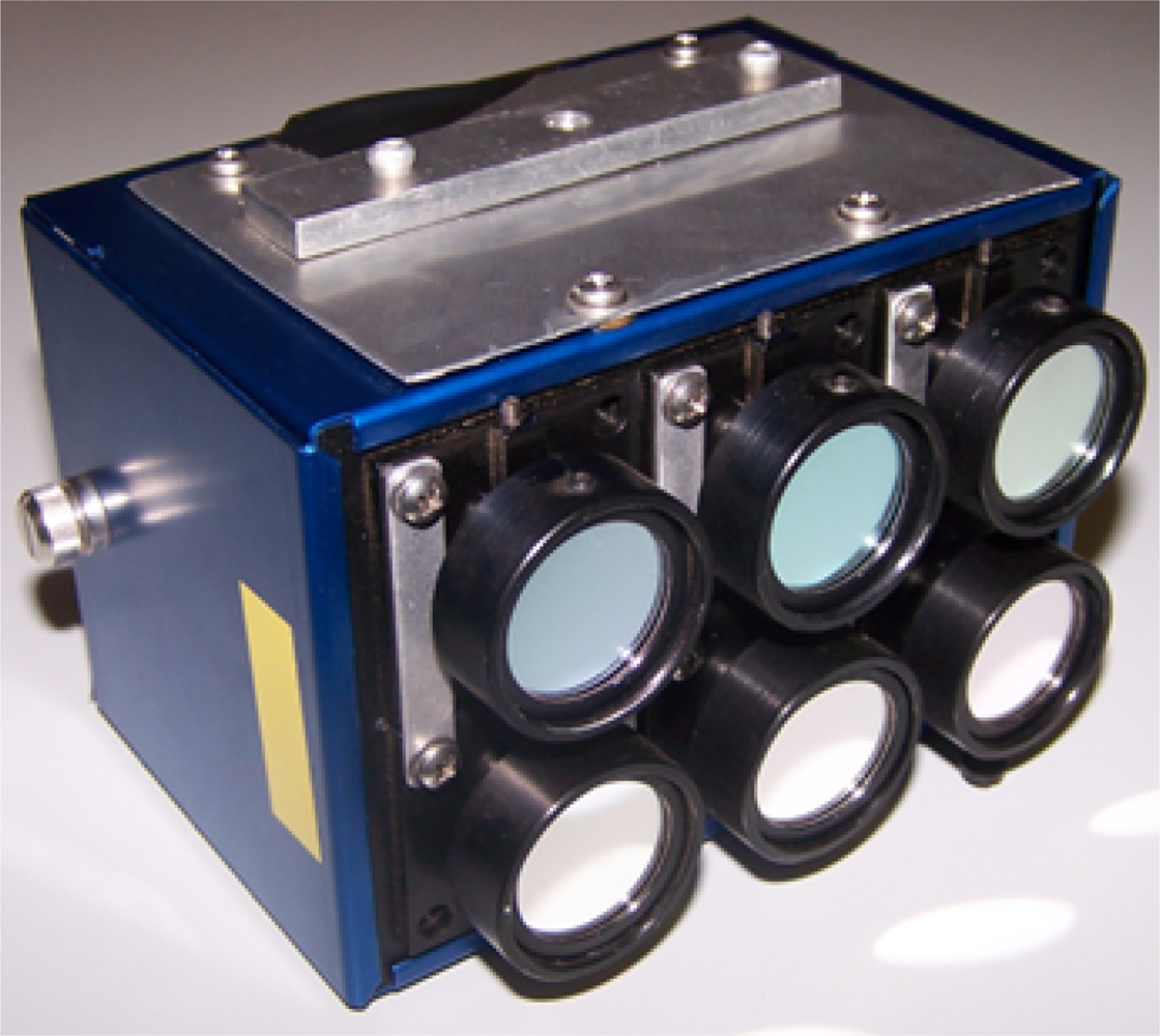
1.1. UAV Multispectral Sensors
2. Methods
2.1. Noise Correction
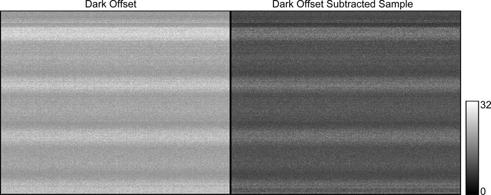
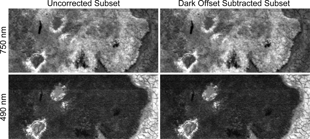
2.1.1. Dark Offset Subtraction
2.1.2. Dark Offset Image Generation Methodology
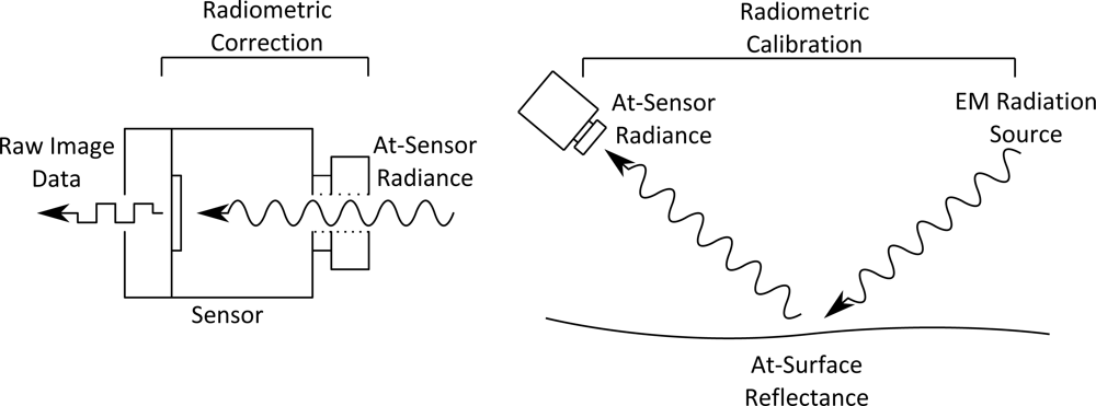
2.2. Radiance Strength Modification
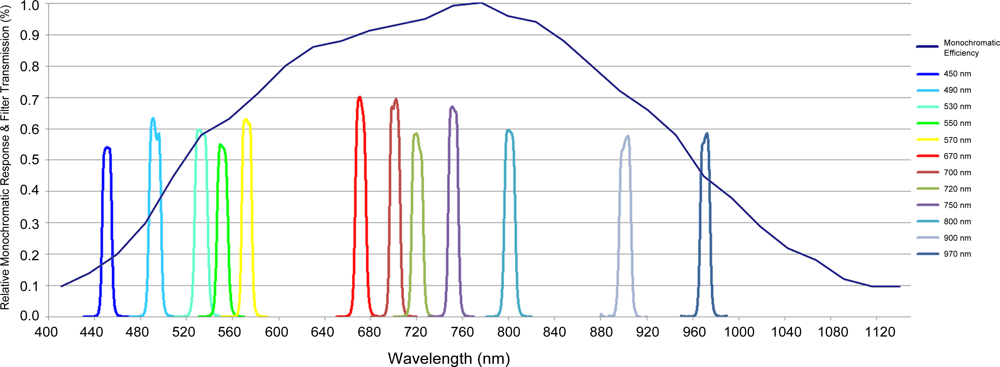
2.2.1. Monochromatic Response
2.2.2. Filter Transmittance
2.3. Wavelength Dependent Correction Factor Methodology
2.3.1. Flat Field Correction Factors
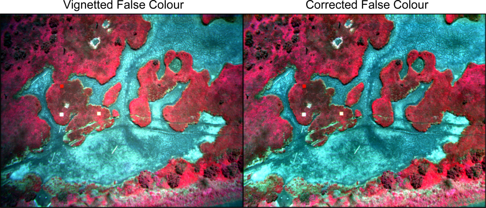
2.3.2. Vignetting Correction Methodology
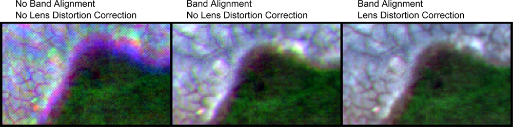
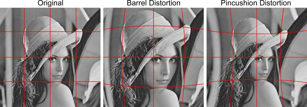
2.4. Lens Distortion
2.4.1. Brown–Conrady Model
2.4.2. Lens Distortion Correction Methodology
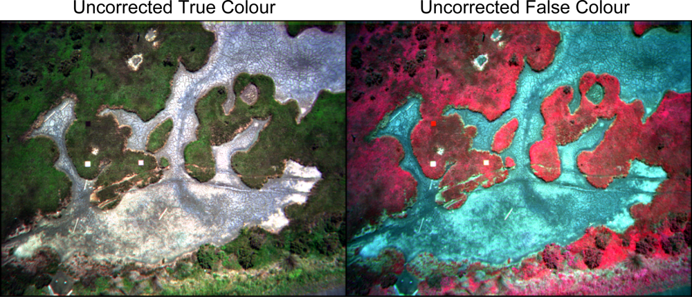
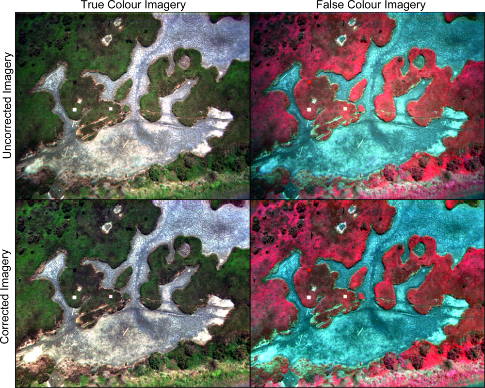
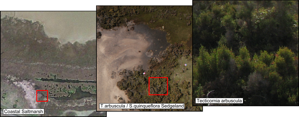
2.5. Salt Marsh Case Study
3. Results
3.1. Dark Offset Subtraction
3.1.1. Global Checkered Pattern
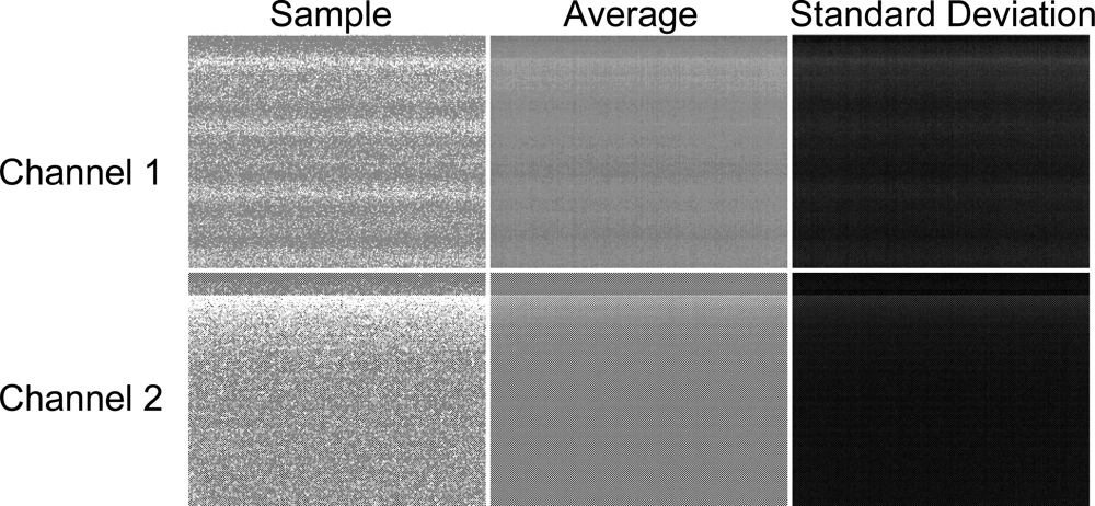
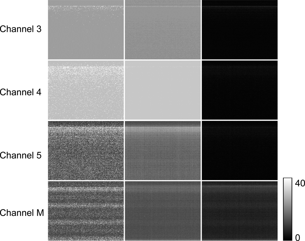
3.1.2. Periodic Noise
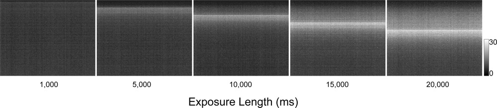
3.1.3. Progressive Shutter Band Noise
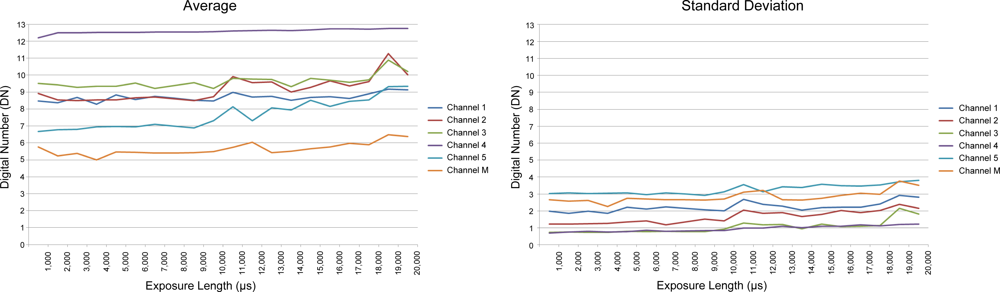
3.2. Dark Offset Potential
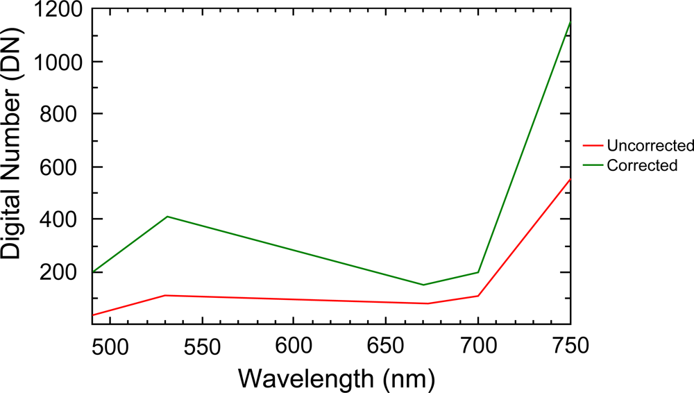
3.3. Filter Transmission/Monochromatic Efficiency
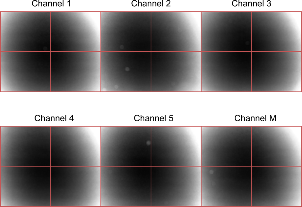
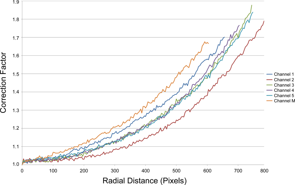
3.4. Vignetting
3.4.1. Effect of Sensors
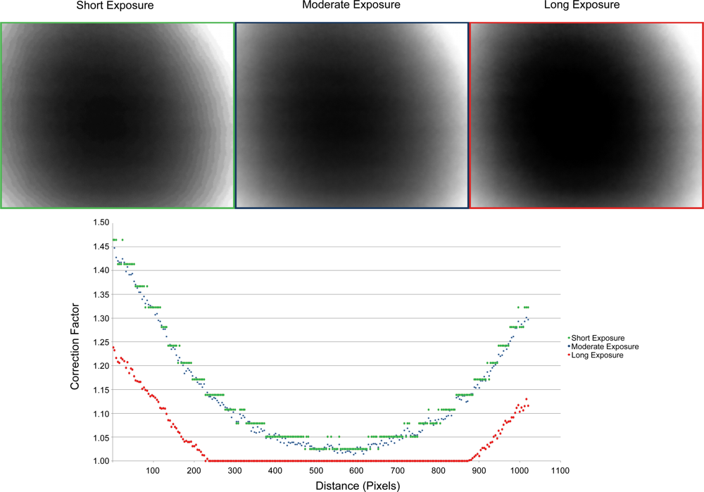
3.4.2. Effect of Exposure
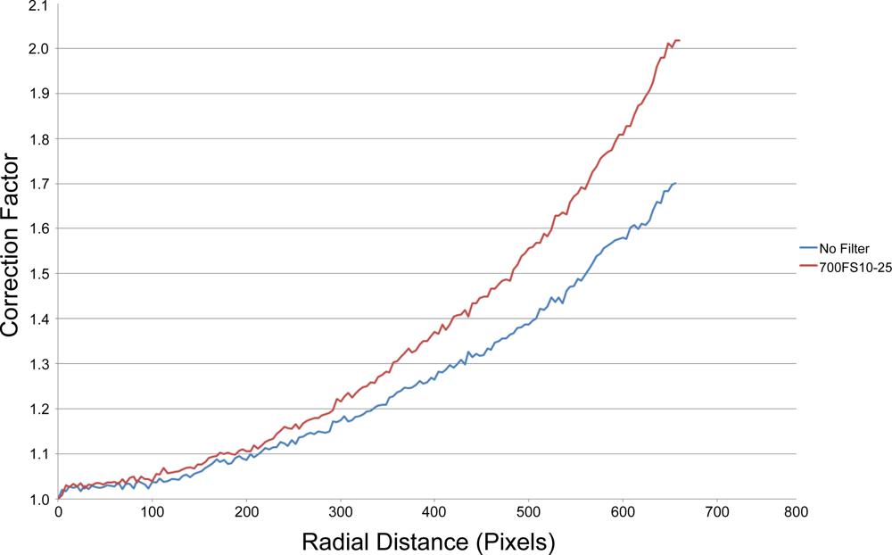
3.4.3. Effect of Filters
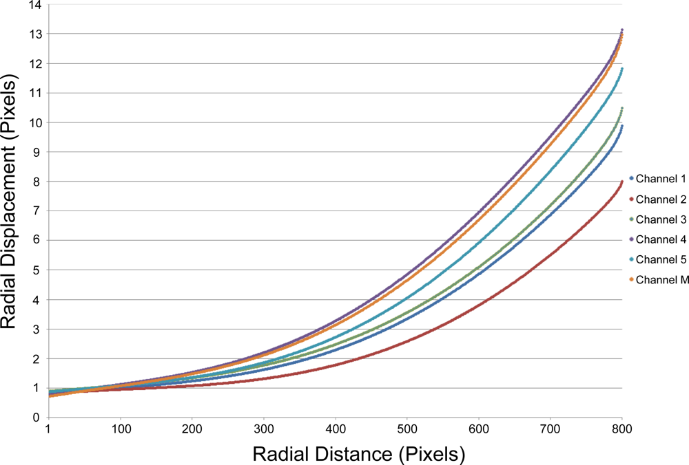
3.5. Lens Distortion
Agisoft Lens Calibration Coefficients
3.6. Salt Marsh Case Study
4. Discussion
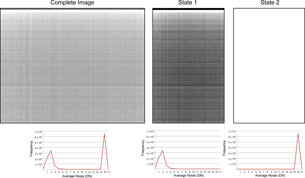
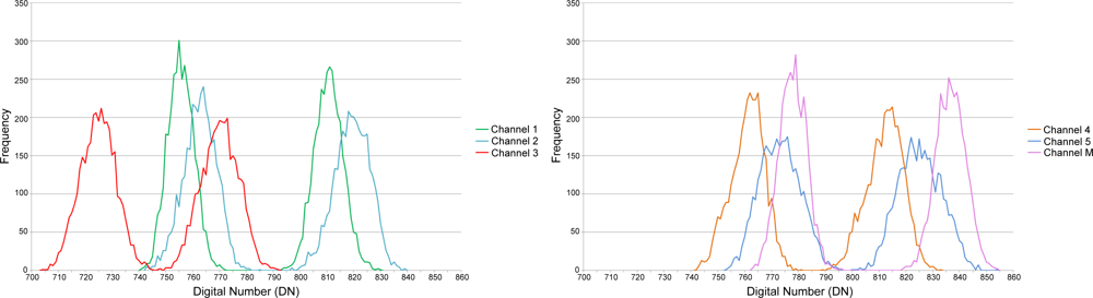
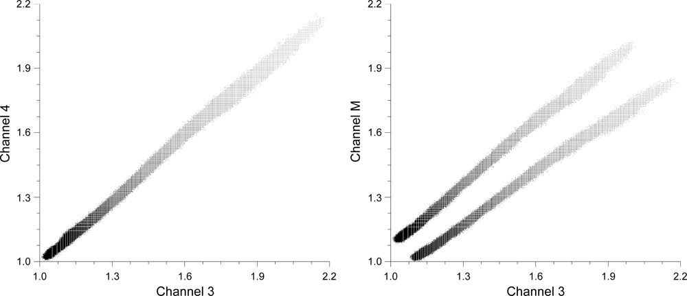
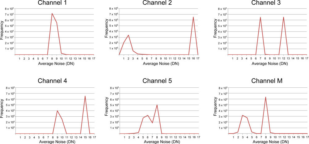
4.1. Channel Dual Distributions
4.2. Vignetting Model
4.3. Sensor Dynamic Range
4.4. UAV Sensor Selection
5. Conclusions
Acknowledgments
References
- Zhou, G.; Ambrosia, V.; Gasiewski, A.; Bland, G. Foreword to the special issue on Unmanned Airborne Vehicle (UAV) sensing systems for earth observations. IEEE Trans. Geosci. Remote Sens 2009, 47, 687–689. [Google Scholar]
- Dunford, R.; Michel, K.; Gagnage, M.; Piegay, H.; Tremelo, M.L. Potential and constraints of Unmanned Aerial Vehicle technology for the characterization of Mediterranean riparian forest. Int. J. Remote Sens 2009, 30, 4915–4935. [Google Scholar]
- Laliberte, A.S.; Rango, A.; Herrick, J. Unmanned Aerial Vehicles for Rangeland Mapping and Monitoring : A Comparison of Two Systems. Proceedings of ASPRS Annual Conference, Tampa, FL, USA, 7–11 May 2007.
- Pastor, E.; Lopez, J.; Royo, P. UAV payload and mission control hardware/software architecture. IEEE Aerosp. Electron. Syst. Mag 2007, 22, 3–8. [Google Scholar]
- Berni, J.; Zarco-Tejada, P.; Suarez, L.; Fereres, E. Thermal and narrowband multispectral remote sensing for vegetation monitoring from an Unmanned Aerial Vehicle. IEEE Trans. Geosci. Remote Sens 2009, 47, 722–738. [Google Scholar]
- Lelong, C.C.D. Assessment of Unmanned Aerial Vehicles imagery for quantitative monitoring of wheat crop in small plots. Sensors 2008, 8, 3557–3585. [Google Scholar]
- Hunt, E.R., Jr.; Hively, W.D.; Fujikawa, S.J.; Linden, D.S.; Daughtry, C.S.T.; McCarty, G.W. Acquisition of nir-green-blue digital photographs from Unmanned Aircraft for crop monitoring. Remote Sens 2010, 2, 290–305. [Google Scholar]
- Laliberte, A.S.; Winters, C.; Rango, A. UAS remote sensing missions for rangeland applications. Geocarto Int 2011, 26, 141–156. [Google Scholar]
- Xiang, H.; Tian, L. Development of a low-cost agricultural remote sensing system based on an autonomous unmanned aerial vehicle (UAV). Biosyst. Eng 2011, 108, 174–190. [Google Scholar]
- Zhao, X.; Liu, J.; Tan, M. A Remote Aerial Robot for Topographic Survey. Proceedings of the 2006 IEEE/RSJ International Conference on Intelligent Robots and Systems, Beijing, China, 9–15 October 2006; pp. 3143–3148.
- Lin, Y.; Hyyppä, J.; Jaakkola, A. Mini-UAV-Borne LIDAR for fine-scale mapping. IEEE Geosci. Remote Sens. Lett 2011, 8, 426–430. [Google Scholar]
- Stefanik, K.V.; Gassaway, J.C.; Kochersberger, K.; Abbott, A.L. UAV-based stereo vision for rapid aerial terrain mapping. GISci. Remote Sens 2011, 48, 24–49. [Google Scholar]
- Rudol, P.; Doherty, P. Human Body Detection and Geolocalization for UAV Search and Rescue Missions Using Color and Thermal Imagery. Proceedings of the 2008 IEEE Aerospace Conference, Big Sky, MN, USA, 1–8 March 2008; pp. 1–8.
- Hinkley, E.A.; Zajkowski, T. USDA forest serviceNASA: Unmanned aerial systems demonstrations pushing the leading edge in fire mapping. Geocarto Int 2011, 26, 103–111. [Google Scholar]
- Pastor, E.; Barrado, C.; Royo, P.; Santamaria, E.; Lopez, J.; Salami, E. Architecture for a helicopter-based unmanned aerial systems wildfire surveillance system. Geocarto Int 2011, 26, 113–131. [Google Scholar]
- Walter, M.; Niethammer, U.; Rothmund, S.; Joswig, M. Joint analysis of the Super-Sauze (French Alps) mudslide by nanoseismic monitoring and UAV-based remote sensing. EGU Gen. Assem 2009, 27, 53–60. [Google Scholar]
- Laliberte, A.; Goforth, M.; Steele, C.; Rango, A. Multispectral remote sensing from unmanned aircraft: image processing workflows and applications for rangeland environments. Remote Sens 2011, 3, 2529–2551. [Google Scholar]
- Clodius, W.B.; Weber, P.G.; Borel, C.C.; Smith, B.W. Multi-spectral band selection for satellite-based systems. Proc. SPIE 1998, 3377, 11–21. [Google Scholar]
- Glenn, E.P.; Huete, A.R.; Nagler, P.L.; Nelson, S.G. Relationship between remotely-sensed vegetation indices, canopy attributes and plant physiological processes: What vegetation indices can and cannot tell us about the landscape. Sensors 2008, 8, 2136–2160. [Google Scholar]
- Lacava, T.; Brocca, L.; Calice, G.; Melone, F.; Moramarco, T.; Pergola, N.; Tramutoli, V. Soil moisture variations monitoring by AMSU-based soil wetness indices: A long-term inter-comparison with ground measurements. Remote Sens. Environ 2010, 114, 2317–2325. [Google Scholar]
- Asner, G.P. Biophysical and biochemical sources of variability in canopy reflectance. Remote Sens. Environ 1998, 64, 234–253. [Google Scholar]
- Smith, M.; Edward, J.; Milton, G. The use of the empirical line method to calibrate remotely sensed data to reflectance. Int. J. Remote Sens 1999, 20, 2653–2662. [Google Scholar]
- Mahiny, A.S.; Turner, B.J. A comparison of four common atmospheric correction methods. Photogramm. Eng. Remote Sensing 2007, 73, 361–368. [Google Scholar]
- Cooley, T.; Anderson, G.; Felde, G.; Hoke, M.; Ratkowski, A.J.; Chetwynd, J.; Gardner, J.; Adler-Golden, S.; Matthew, M.; Berk, A.; et al. FLAASH, A MODTRAN4-Based Atmospheric Correction Algorithm, Its Application and Validation. Proceedings of the IEEE International Geoscience Remote Sensing Symposium, Toronto, ON, Canada, 24–28 June 2002; 3, pp. 1414–1418.
- Al-amri, S.S.; Kalyankar, N.V.; Khamitkar, S.D. A comparative study of removal noise from remote sensing image. J. Comput. Sci 2010, 7, 32–36. [Google Scholar]
- Mansouri, A.; Marzani, F.; Gouton, P. Development of a protocol for CCD calibration: Application to a multispectral imaging system. Int. J. Robot. Autom 2005, 20. [Google Scholar] [CrossRef]
- Chi, C.; Zhang, J.; Liu, Z. Study on methods of noise reduction in a stripped image. Int. Arch. Photogramm. Remote Sens. Spat. Inf. Sci 2008, 37, Part 6B. 213–216. [Google Scholar]
- Mullikin, J.C. Methods for CCD camera characterization. Proc. SPIE 1994, 2173, 73–84. [Google Scholar]
- Goldman, D.B. Vignette and exposure calibration and compensation. IEEE Trans. Pattern Anal. Mach. Intell 2010, 32, 2276–2288. [Google Scholar]
- Kim, S.J.; Pollefeys, M. Robust radiometric calibration and vignetting correction. IEEE Trans. Pattern Anal. Mach. Intell 2008, 30, 562–576. [Google Scholar]
- Zheng, Y.; Lin, S.; Kambhamettu, C.; Yu, J.; Kang, S.B. Single-image vignetting correction. IEEE Trans. Pattern Anal. Mach. Intell 2009, 31, 2243–2256. [Google Scholar]
- Yu, W. Practical anti-vignetting methods for digital cameras. IEEE Trans. Consum. Electron 2004, 50, 975–983. [Google Scholar]
- Wang, A.; Qiu, T.; Shao, L. A simple method of radial distortion correction with centre of distortion estimation. J. Math. Imag. Vis 2009, 35, 165–172. [Google Scholar]
- Prescott, B. Line-based correction of radial lens distortion. Graph. Model. Image Process 1997, 59, 39–47. [Google Scholar]
- Hugemann, W. Correcting Lens Distortions in Digital Photographs; Ingenieurbüro Morawski + Hugemann: Leverkusen, Germany, 2010. [Google Scholar]
- Park, J.; Byun, S.C.; Lee, B.U. Lens distortion correction using ideal image coordinates. IEEE Trans. Consum. Electron 2009, 55, 987–991. [Google Scholar]
- Jedlička, J.; Potčková, M. Correction of Radial Distortion in Digital Images; Charles University in Prague: Prague, Czech, 2006. [Google Scholar]
- de Villiers, J.P.; Leuschner, F.W.; Geldenhuys, R. Modeling of radial asymmetry in lens distortion facilitated by modern optimization techniques. Proc. SPIE 2010, 7539, 75390J:1–75390J:8. [Google Scholar]
- Wang, J.; Shi, F.; Zhang, J.; Liu, Y. A New Calibration Model and Method of Camera Lens Distortion. Proceedings of 2006 IEEE/RSJ Int. Conf. Intell. Robot. Syst., Beijing, China, 9–15 October 2006; pp. 5713–5718.
- Adam, P. Saltmarshes in a time of change. Environ. Conserv 2002, 29, 39–61. [Google Scholar]
- Emery, N.C.; Ewanchuk, P.J.; Bertness, M.D. Competition and salt-marsh plant zonation: Stress tolerators may be dominant competitors. Ecology 2001, 82, 2471–2485. [Google Scholar]
- Pennings, S.C.; Callaway, R.M. Salt marsh plant zonation: The relative importance of competition and physical factors. Ecology 1992, 73, 681–690. [Google Scholar]
- Puissant, A.; Hirsch, J.; Weber, C. The utility of texture analysis to improve per-pixel classification for high to very high spatial resolution imagery. Int. J. Remote Sens 2005, 26, 733–745. [Google Scholar]


| Filter (nm) | Transmission (%) | Correction Factor | Monochromatic Relative Efficiency (%) | Correction Factor | Multiplicative Correction Factor |
|---|---|---|---|---|---|
| 450 | 0.44 | 2.28 | 0.16 | 6.25 | 14.27 |
| 490 | 0.47 | 2.13 | 0.34 | 2.97 | 6.32 |
| 530 | 0.47 | 2.12 | 0.56 | 1.80 | 3.81 |
| 550 | 0.45 | 2.21 | 0.62 | 1.61 | 3.57 |
| 570 | 0.44 | 2.26 | 0.67 | 1.49 | 3.38 |
| 670 | 0.56 | 1.80 | 0.91 | 1.10 | 1.98 |
| 700 | 0.56 | 1.79 | 0.93 | 1.08 | 1.92 |
| 720 | 0.51 | 1.96 | 0.95 | 1.05 | 2.06 |
| 750 | 0.49 | 2.02 | 0.97 | 1.03 | 2.09 |
| 900 | 0.48 | 2.07 | 0.71 | 1.40 | 2.90 |
| 970 | 0.47 | 2.14 | 0.45 | 2.22 | 4.75 |
| Date | Site | Longitude | Latitude | Height (m) | Exposure (μs) |
|---|---|---|---|---|---|
| 25/11/2012 | Ralphs Bay | 42 55.742′S | 147 29.036′E | 100 m | 4,000 |
| Channel | State | Average | StDev | Skew |
|---|---|---|---|---|
| 1 | 1 | 8.445 | 0.650 | −3.379 |
| 2 | 8.452 | 0.6817 | −2.987 | |
| 2 | 1 | 1.828 | 0.884 | 1.559 |
| 2 | 15.972 | 0.670 | −23.798 | |
| 3 | 1 | 6.999 | 0.317 | −18.182 |
| 2 | 11.981 | 0.504 | −23.543 | |
| 4 | 1 | 9.374 | 0.626 | −5.627 |
| 2 | 14.974 | 0.628 | −23.801 | |
| 5 | 1 | 7.757 | 0.542 | −5.664 |
| 2 | 5.527 | 0.747 | −1.094 | |
| M | 1 | 8.020 | 0.449 | −10.784 |
| 2 | 3.508 | 0.762 | 1.247 |
| Channel | cx | cy | k1 | k2 | p1 | p2 | Fx | Fy |
|---|---|---|---|---|---|---|---|---|
| 1 | 629.169 | 465.738 | −0.068745 | 0.0623006 | −0.000639335 | −0.000509879 | 1622.5 | 1622.5 |
| 2 | 628.961 | 464.003 | −0.0579649 | 0.0356426 | −0.000102067 | −0.00221439 | 1606.81 | 1606.81 |
| 3 | 632.575 | 472.777 | −0.0506697 | 0.021484 | 0.000077687 | 0.0011317 | 1625.74 | 1625.74 |
| 4 | 633.999 | 470.756 | −0.0912427 | 0.132531 | −0.000135051 | 0.00124068 | 1623.55 | 1623.55 |
| 5 | 632.498 | 470.568 | −0.0748613 | 0.0729301 | 0.000851022 | −0.000399902 | 1625.88 | 1625.88 |
| M | 638.965 | 460.592 | −0.0922108 | 0.124107 | 0.000614466 | 0.000842289 | 1619.26 | 1619.26 |
Share and Cite
Kelcey, J.; Lucieer, A. Sensor Correction of a 6-Band Multispectral Imaging Sensor for UAV Remote Sensing. Remote Sens. 2012, 4, 1462-1493. https://doi.org/10.3390/rs4051462
Kelcey J, Lucieer A. Sensor Correction of a 6-Band Multispectral Imaging Sensor for UAV Remote Sensing. Remote Sensing. 2012; 4(5):1462-1493. https://doi.org/10.3390/rs4051462
Chicago/Turabian StyleKelcey, Joshua, and Arko Lucieer. 2012. "Sensor Correction of a 6-Band Multispectral Imaging Sensor for UAV Remote Sensing" Remote Sensing 4, no. 5: 1462-1493. https://doi.org/10.3390/rs4051462
APA StyleKelcey, J., & Lucieer, A. (2012). Sensor Correction of a 6-Band Multispectral Imaging Sensor for UAV Remote Sensing. Remote Sensing, 4(5), 1462-1493. https://doi.org/10.3390/rs4051462