Abstract
This study proposes a novel technique for detecting aerial moving targets using multiple satellite radars. The approach enhances the image contrast of fused local three-dimensional (3D) profiles. Exploiting global navigation satellite system (GNSS) satellites as illuminators of opportunity (IOs) has brought remarkable innovations to multistatic radar. However, target detection is restricted by radiation sources since IOs are often uncontrollable. To address this, we utilize satellite radars operating in an active self-transmitting and self-receiving mode for controllability. The main challenge of multiradar target detection lies in effectively fusing the target echoes from individual radars, as the target ranges and Doppler histories differ. To this end, two periods, namely the integration period and detection period, are precisely designed. In the integration period, we propose a range difference-based positive and negative second-order Keystone transform (SOKT) method to make range compensation accurate. This method compensates for the range difference rather than the target range. In the detection period, we develop two weighting functions, i.e., the Doppler frequency rate (DFR) variance function and smooth spatial filtering function, to extract prominent areas and make efficient detection, respectively. Finally, the results from simulation datasets confirm the effectiveness of our proposed technique.
1. Introduction
The spaceborne distributed radar network (DRN) generously combines the advantage of spaceborne radar, which allows wide-area surveillance unrestricted by the Earth’s curve and national boundaries, with the cooperative operation of multiple radars in the DRN, which enhances diverse characteristics and reduces the power-aperture product, compared to traditional radars with large, heavy antennas. Hence, spaceborne DRN is considered one of the most promising spaceborne radar systems to improve the detection, estimation, and tracking capabilities of moving targets, and has been extensively investigated in recent decades [1,2,3,4].
With the development of DRNs, there has been an emergence of various operation modes and topological configurations. Judging by whether illuminators of opportunity (IOs) are from the DRNs or not, they are mainly categorized into three types: passive DRNs [5,6,7], active/passive DRNs [8,9], and active DRNs [10]. Passive DRNs refer to node radars within their network that only receive signals passively. The illuminated signals are provided by satellite-based transmitters, ground-based transmitters, and typical wireless network services. Active/passive DRNs are those in which the transmitting radars and receiving radars are spatially separated, but still confined by the network, i.e., bistatic multiple-input multiple-output (MIMO). Active DRNs are composed of node radars, each of which functions as a transceiver. Notice that the IOs of a passive DRN are from third-party sources and, hence, often out of control for surveillance. Additionally, the signal processing architecture in an active/passive DRN is somewhat sophisticated. In this work, we opt for an active DRN, where the radars transmit orthogonal waveforms, but only receive the propagation signals from themselves to balance the trade-off.
Generally, two kinds of techniques are known to boost moving target detection with DRNs. The first category attempts to increase target SNR gain by integrating the target echoes over a long time in order to counteract the weak signal power. However, due to the target motion, it is inevitable to encounter range migration and Doppler spreading during the observation period. If the target SNR were large enough, it would be adequate to accumulate the target energy using only target echo amplitudes in a non-coherent way by Radon transform [11] or Hough transform [12]. However, for the target with a relatively low SNR, researchers have devoted several effective algorithms such as Keystone transform (KT) [13,14,15], Radon–Fourier transform (RFT) [16,17], axis rotation moving target detection (AR-MTD) [18], time reversing transform (TRT) [19], etc., to coherently integrating target echoes. Here, it is worthwhile to note that the order of Taylor-series expansion should be correctly determined. Higher-order expansion leads to heavy calculation burden, whereas lower-order expansion suffers from focusing difficulty.
The second category that raises the detection performance involves accumulating the target echoes among node radars. Tenney and Sandells’ pioneering work in [20] expands the classical detection problem to the scenario of distributed sensors within the decentralization process. It implies that local detection decisions are made independently by sensors before they are fed into the fusion center (FC). Subsequently, refs. [21,22] focus on optimum detectors of distributed radars in the sense of the Neyman–Pearson (NP) criterion. In terms of decision types, decentralized detections can be further divided into decentralized hard decisions [23,24] and decentralized soft decisions [25,26], where the former types yield a hard decision value of 0 or 1, whereas the latter types determine a soft value between 0 and 1. In contrast, centralized detections [27] involve the transfer of collected observations among sensors directly to the FC to make a global decision. Centralized detections are expected to achieve better detection performances, as the degradation caused by local radar decisions can be greatly alleviated. Fishler et al. develop the optimum centralized detector for distributed MIMO radar in Gaussian background noise [28,29], where the spatial diversity is utilized to combat the target scintillation. For more complex interference backgrounds, moving target detection problems are investigated in homogeneous clutter in [30], non-homogeneous clutter in [31], and non-Gaussian heterogeneous clutter in [32]. Additionally, Chen et al. explore the case of moving platforms equipped with multiple collocated antennas [33]. Local decisions and observations by node radars contribute to the detection quite differently, whether in a decentralized or centralized architecture. Therefore, the global test statistics, which weight coefficients by local performance, should be considered heuristically [34].
Satellite-based illuminators are commonly used in imaging and detection for their precise orbit control and unconstrained area monitoring. The GNSS-based passive radar, as presented in [35], is the first attempt to validate this concept for observing sea level variation. The broad bandwidth of navigation signals has led to extensive attention to passive SAR imaging theories, algorithms, and systems [36,37]. Apart from imaging, there exist well-established applications for detecting moving targets. In [38], the experiment of aerial moving target detection is examined using a GPS forward-scattering radar, which serves as a countermeasure to the stealth technique. Ma et al. introduce the concept of using GNSS as IOs to detect maritime targets [39]. To make long integration more practical, ref. [40] adopts a hybrid approach, combining coherent integration within shorter frames and non-coherent integration between frames in the integration window. The investigators also suggest jointly exploiting long integration time and multiple transmitters to enhance system performance [41]. Relying on the BeiDou system, ref. [42] proposes to project the original range-DFR maps into the X-Y-V domains to implement the echo integration, locating maritime targets and estimating their velocities simultaneously. Ref. [43] explores the DFR separability between clutter and targets in satellite constellations, which improves the target detection performance in clutter backgrounds. However, these studies mainly concentrate on passive DRNs, with rare mention of active DRNs.
Employing active DRNs has more advantages than employing passive DRNs. In this paper, the approach using distributed satellites to detect aerial moving targets via a contrast-enhanced approach is proposed, where the self-transmitting and self-receiving mode is chosen to balance target detection and link complexity. Particularly, Doppler frequency rates (DFRs) are taken into account to enhance aerial moving target detection. Unlike the previous studies in [42,43], our approach not only uses DFRs to distinguish targets from background clutter, but also refines detection areas with smooth spatial filtering.
Two main reasons are listed here to explain why we have opted for active DRNS instead of passive DRNs. (a) The illuminators of opportunity of passive DRNs have their own specific functions that are not dedicated to radar detection purposes. In this way, they are often out of control and power-limited. As a result, radar detection ranges may be restricted due to limited power budgets. (b) One of the main original purposes for passive DRNs is to enable node stealth ability and, hence, to improve radar anti-jamming ability and even survivability. However, our DRNs are deployed in space, namely, spaceborne DRNs. The main purpose is to obtain a wider range of coverage instead of improving stealth ability. It would be a greater price to interfere with spaceborne nodes than with ground-based or airborne nodes.
The remaining parts are outlined as follows. In Section 2, the general signal model and the contrast-enhanced aerial moving target detection method are discussed in detail. The numerical results are shown in Section 3 to verify the effectiveness of the proposed method, and the corresponding advantages are summarized in Section 4. Finally, the work ends with some concluding remarks in Section 5.
2. Materials and Methods
2.1. Basic Signal Model
The general configuration of the distributed satellite for aerial moving target detection is depicted in Figure 1. The system is composed of satellite radars that operate in a self-transmitting and self-receiving mode to search the object of interest. Once the six orbit elements of satellites are fixed, the satellite motion states can be determined to obtain the kth satellite position . Furthermore, by taking the derivative of position with respect to time, we have the satellite velocity . This assumes that an aerial moving target at the coordinates is illuminated in the area overlapped by satellite radar beams and is moving with a constant velocity . The target is expected to be completely observed by all satellite radars throughout the observation period so that the target echoes during the coherent processing interval (CPI) can be effectively integrated. To this end, a long-time coherent integration is performed within each radar, followed by data fusion among radars, to enhance target detection.
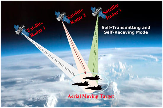
Figure 1.
Distributed satellite observation geometry.
Consider satellite radars transmit mutually orthogonal waveforms, where the linear frequency modulation (LFM) (or chirp) baseband waveform is chosen. The kth transmitting signal is of the form
where
is the rectangle window function, is the pulse duration, is the chirp rate with the signal bandwidth , is the carrier frequency, and is the kth orthogonal modulation phase so that
is maintained.
After the orthogonal waveform separation and pulse compression operation, the kth radar only captures its self-transmitting and self-receiving signal component, written as
where is the carrier wavelength, is the sinc function, is the target complex amplitude received by the kth radar, is the receiving noise, and is the instantaneous range at the time instant from the kth radar to the target. Moreover, can be expressed as
where stands for the initial range at ,
represents the kth Doppler centroid (DC) at , and
stands for the kth Doppler frequency rate (DFR) at the instant . To continue, transform the received signal in (4) in the fast-time domain into the range-frequency domain yielding
where is the range-frequency noise. Substituting (5) into (8), we can observe that the terms and are both tightly coupled with the frequency , which incurs severe target range migrations (RMs) and Doppler frequency migrations (DFMs). These RMs and DEMs would distort the original signal phase and lead to integration collapse. In this way, one must remove these imperfections first before proceeding with long-time coherent integration.
2.2. Contrast-Enhanced Aerial Moving Target Detection Using Satellite Constellation
The main purpose of this paper is to effectively detect aerial moving targets with satellite radars operating in an active self-transmitting and self-receiving mode. This section details the proposed approach for enhancing contrast using distributed satellite radars to detect aerial moving targets through data fusion. The procedure involves a long-time coherent/noncoherent integration period and a detection period based on multiradar fusion [40,41,42]. Figure 2 illustrates a flow chart that details our proposed contrast-enhanced aerial moving target detection scheme.
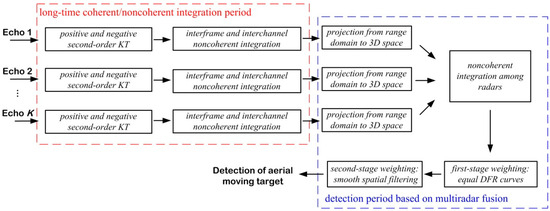
Figure 2.
The contrast-enhanced aerial moving target detection scheme.
2.2.1. Long-Time Coherent/Noncoherent Integration
To achieve coherent integration, we introduce the positive and negative SOKT method inside each frame to balance integration gain and computational burden. For noncoherent integration, these signal outputs are added together between frames to obtain the noncoherent integration gain , where is the frame number.
- The positive and negative SOKT method using range difference
In (5), a second-order Taylor-series expansion is used to approximate the instantaneous range. However, the approach lacks accuracy since it unfortunately omits the higher-order Taylor-series expansion terms. While involving more expansion terms would improve the approximation accuracy, it would also make the compensation more complicated. On the other hand, one can reach a more precise approximation by applying the one-order Taylor-series expansion to the range difference, compared to the instantaneous range. As illustrated in Figure 3, it is clear that the approximation errors between the actual values and the approximated values are less for the range difference than for the satellite range.
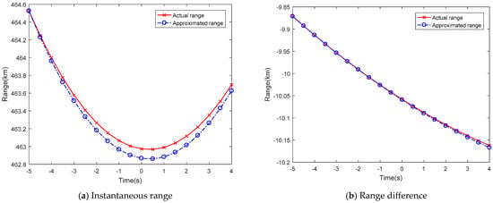
Figure 3.
The comparisons of actual ranges and approximated ranges by the Taylor-series technique.
Define the instantaneous range difference at the time instant
where is the satellite range, is the kth initial range difference at with , and
and
are defined by the DC difference and DFR difference at , respectively.
With this in mind, we first structure a range frequency compensation function
in the range-frequency domain. Thus, the instantaneous range is converted into the range difference, i.e.,
Then, according to the positive SOKT
we can obtain
where is the noise with respect to the positive transformation. Similarly, apply the negative SOKT
yielding
where is the negative version of noise. Multiplying (15) by (17), one can arrive at
where is synthesized amplitude and is the multiplied noise, assuming that the signal component in (15) (in (17)) and noise components in (17) (in (15)) are uncorrelated with each other. Moving forward, we apply the inverse fast Fourier transform (IFFT) technique to (18) in the range-frequency domain:
where is the rescaled noise. Upon (19), we observe that is no longer coupled with , but it still has a connection to , which results in the range curve, unless the coupling term is appropriately compensated. Consequently, a two-dimensional (2D) match filtering function in the rescaled slow-time domain is introduced by
to eliminate the residual nuisance, yielding
where the coherent integration gain has been absorbed into the complex amplitude and is the integrated noise. With the technique mentioned above, target echoes can be integrated coherently within a frame.
- Interframe and interchannel target noncoherent integration
The detection of aerial moving targets using satellite radars requires a very long observation period to increase the target SNR. However, as we stated earlier, the accuracy of using the Taylor-series expansion for the instantaneous range decreases as the integration period within a frame is longer. Therefore, it is reasonable to integrate target echoes between frames in a noncoherent way to avoid signal defocusing.
Based on (21), a DFR grid is introduced to collect the outputs after the 2D match-filtering process by using (20). It is important to carefully design the DFR grid because an overly dense grid may cause the output signal to leak into adjacent grids. On the other hand, a sparser grid may lead to a loss of perfect coherence, resulting in only a shrinkage gain by the relatively closest grid. To address this, we perform an oversampled 2D match filtering to produce output channels, and then each group of subchannels is integrated noncoherently to yield grids. For more detailed criterion on DFR grid design, one can refer to Section 4.
The underlying 2D noncoherent signal processing is described by:
where is the generalized expression of in (21) with respect to the th subchannel and th frame.
2.2.2. Contrast-Enhanced Target Detection Method via Multiradar Data Fusion
It has been confirmed that DRN is not only able to provide spatial diversity to counteract target RCS fluctuations. More importantly, it can also be used to enhance target localization. This is achieved through the intersection of geometric curves like isorange rings, ellipsoids, hyperbolas, etc. In these scenarios, target localization is implemented after acquiring the target of interest. Alternatively, it is feasible to project the processed data from the range-fdr domain into the X-Y-Z-fdr domain to initially obtain the isorange rings before subsequent detection. To this end, this method takes two types of knowledge regarding image contrast into account, namely the approximately equal target DFRs among radars and the smooth spatial filter highlighting the detection area, to improve multiradar target detection ability.
- Noncoherent integration among radars in the X-Y-Z-fdr domain
Aside from integrating signals over a long observation time within individual radars, the detection of moving targets can also be improved by accumulating the signal outputs from all participating radars noncoherently. Traditionally, coordinating signal registration in the range-DFR domain among different radars has been a great challenge for multiradar detection, as depicted in Figure 4a. Nevertheless, recent techniques proposed in [40,41] involve projecting the target echoes in the range domain into 3D space, as shown in Figure 4b. In this way, multiple radars can share the common reference framework to facilitate multistatic radar detection.
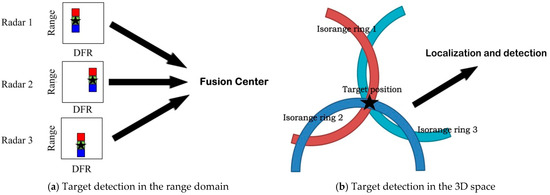
Figure 4.
Two types of multiradar detection.
Given a fixed time instant , where is the range difference sampled at , we project the range difference into its corresponding coordinate in the 3D space, expressed as
Hence, a 3D data cube, the element of which is filled with the data at , isorange to , is formed, yielding
Especially, for the target case, it yields .
It is worthwhile to note here that radar only produces isorange rings, which means that the target position is still ambiguous after the projection. However, when multiple radars participate, these isorange rings from their own radars intersect, allowing the target position to be uniquely determined. The fusion of multiradar data involving the noncoherent integration of K images is
Performing noncoherent integration in such space has the following potential advantages.
- (1)
- Such space acts as a common reference when multiple radars are exploited; thus, the operation can be applied directly.
- (2)
- No simplifying range polynomial models are considered; therefore, a complete compensation is allowed to track the exact range to yield higher integration gain.
However, the integration needs to be sequentially evaluated for each position, thus increasing the computational load. We are aware that such a way would introduce heavy computational costs. Nevertheless, it can provide more accurate compensation to obtain higher integration gain.
- An enhanced-contrast target detection based on two-stage weighting
In [41], an LRT detector is developed to combine the projected images pertaining to different frames and radars. Ref. [42] further takes DFR into account. However, the potential interference, which can obscure targets and lead to false alarms, is thoroughly addressed. On the other hand, it is not difficult to confirm that targets are typically located in the intersection area. As a result, it is not necessary to conduct a thorough search across every pixel in the image to capture the target, thus reducing computational complexity. Concerning these two factors, we propose a two-stage weighting approach for aerial moving target detection via a contrast-enhanced method. Here, enhancing the contrast means that we reweight the fused image using two weighting functions.
In the first stage, we utilize the property that different radars share an approximately equal target DFR, which is not difficult to verify from DFR definition. Similar to intersecting isorange rings to resolve target position, one can also determine the existence of a target by overlapping equal DFR curves. This method allows equal DFR curves to identify false targets before target detection. The first-stage weighting function is as follows:
where the exponent of the variance function is used as the tool to evaluate the weighting coefficient in the first stage. If the DFRs of image points from each radar are roughly equal, then the intensity remains unchanged. Otherwise, the intensity would be significantly attenuated.
Actually, the target area is sparse relative to the entire detection space. As a result, it is unnecessary to search each pixel to censor potential targets. The smooth spatial filtering technique is commonly used for noise reduction, and more importantly, it can be used to eliminate irrelevant details, while preserving the area of interest. We resort to smooth spatial filtering to extract specific local regions in the second stage, making the detection procedure more efficient. Additionally, the distance between pixels is considered the attenuation kernel in the design of smooth spatial filtering. Consequently, the second-stage weighting function is
where is the index vector, is the distance-dependent forgetting factor, and , , and are the slide window lengths in three dimensions. From (27), we can assume that the high-intensity area would be strengthened more, whereas the low-intensity area would be further suppressed. It can be concluded that the whole image is weighted during the first-stage processing, while the second-stage processing concentrates only on the detection area. Hence, the image contrast is enhanced, and it further improves the detection.
We discuss the target detection procedure to determine the absence of a target using the null hypothesis or the presence of a target using the alternative hypothesis . Based on the projection, the binary hypothesis test is formulated as
where is the threshold used to judge whether or not to detect the image point during the second-stage processing, is the determined target power, and is modeled as white Gaussian noise characterized by its power . The noises are assumed to be uncorrelated among different pulses and radars.
3. DFR Grid Design Criterion
For long-time coherent integration, off-grid filtering will occur if the target DFR is not aligned with the frequency center of the corresponding DFR filter. This misalignment can cause remarkable integration loss. One way to avoid this is by conducting a fine search across the DFR search interval. However, performing a fine search leads to inconsistencies in the DFR target output channels between different radars, potentially causing image defocusing (signal dispersion) during multi-radar data fusion [43,44].
A viable solution to resolve this problem is to merge several neighboring channels into a grid using a noncoherent process. This helps prevent image defocusing. Meanwhile, when compared with a coarse search by directly reducing the DFR filters, our approach can significantly lower the impact of off-grid filtering on the channel output. The next challenge is to consider the size of the DFR grid, which is equivalent to the number of channels grouped in a grid. We need to focus on two main issues: Firstly, the grid size should be chosen to meet the requirement of separating the potential target from the clutter background, especially the mainlobe clutter. Secondly, we need to ensure that the target echoes from different radars can be collected in the same resulting grid to produce an acceptable focusing result during the grid size design [45].
More concretely, the upper bound of the grid size should meet the condition for separating the target with the minimum detectable velocity (MDV), i.e., the radial velocity closest to the mainlobe clutter at which the acceptable SINR loss occurs, from the mainlobe clutter. Then, once the satellite constellation is fixed, the corresponding MDV is represented by . In this way, for the kth satellite radar, the DFR grid size should satisfy
where is the minimum DFR of the target with the MDV, is the DFR of the closest mainlobe clutter, and is the clutter coordinate. Furthermore, by involving all radars, it yields
For the lower bound of the grid size, the MDV target returns from different radars must be collected in the same DFR grid to serve further data fusion. In other words, we should guarantee that half of the grid is no less than the target DFR difference between any two radars, i.e.,
Also, involving all radars gives rise to
Combining (30) and (32), the DFR grid design criterion is formulated by
4. Results
This section includes several simulation experiments to validate the effectiveness of our proposed technique for detecting aerial moving targets. We focus on a satellite constellation consisting of satellites that operate in a self-transmitting and self-receiving mode. We assume that the area of interest is observed by multiple overlapped beams intentionally scheduled to steer to the same region from individual satellite radars. The satellite orbit parameters are listed in Table 1. All radars operate at the UHF band, and the PRF is fixed at 1000 Hz. The signal bandwidth is 50 MHz, and the pulse width is 50 . The aerial moving target is initially located at the coordinates [5e3, 1e3, 10e3]Tm, and during the observation period, the target maintains a constant flight speed of 10 m/s.

Table 1.
Satellite basic orbit parameter.
The DFR grid design is first concerned about and followed by the validation of the proposed contrast-enhanced target detection via multiradar data fusion.
4.1. Evaluation of DFR Grid Design
As mentioned in Section 4, the design of the DFR grid is related to system parameters, motion states, and observation geometry determined by the radars and observed target. More concretely, its upper bound is ruled by the separation between the target and clutter background, whereas the lower bound is restricted by the condition that the target echoes from their radars can precisely focus on the same grid. Following this, we depict the lower bound and upper bound of the DFR grid size versus target incident angle and target velocity in Figure 5a,b, respectively.
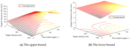
Figure 5.
The upper and lower bounds of the DFR grid size versus target incident angle and target velocity.
In the region of low incident angles, both the upper and lower bounds of the DFR grid size get smaller as the target velocity increases, while in high incident angles, the two sizes become larger. In practical scenarios, the offline grid size can be calculated based on prior information to facilitate multiradar data fusion.
Furthermore, the two principal cuts of the mesh plots, which are at the target incident angle and fixed target velocity , are shown in Figure 6a,b, respectively. The solid red line indicates the DFR grid size upper bound, whereas the dashed blue line denotes its lower bound.
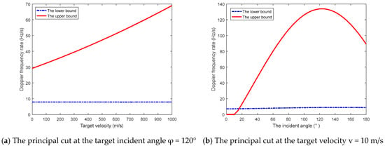
Figure 6.
Two principal cuts of the DFR grid size mesh plots at the fixed angle and velocity.
Based on the two figures provided, we observe that the lower bound changes much slower in comparison to the upper bound. Some circumstances should raise much attention, such as the target with the incident angle 0~10° by the speed of . In these cases, it must be emphasized that the lower bound surpasses the upper bound, and hence, a suitable size never exists. Consequently, detecting aerial moving targets is obviously infeasible.
4.2. Evaluation of Long-Time Coherent/Noncoherent Integration
Firstly, we elaborate on the proposed technique for long-time coherent/noncoherent integration. In Figure 7a, we display the original target echo for a long-time integration period. The envelope of the target echo varies with time, leading to range cell migration. In Figure 7b–e, we present the corrected envelopes of the target echoes using the SOKT method, positive and negative SOKT method, range-difference based SOKT method, and our proposed range-difference-based positive and negative SOKT method, respectively. We show that the target range curve still exists by the traditional range-based method. The performance obtained by the positive and negative SOKT method is worse than the SOKT method with only positive transformation. This implies that the Taylor-series approximation is not accurate enough to justify the compensation. On the other hand, the proposed method produces more accurate results compared to the range-difference-based SOKT method with only positive transformation, again highlighting the importance of an accurate Taylor-series approximation. Our proposed method shares the merits of both an accurate Taylor-series approximation and more precise motion compensation, thus yielding the better range cell migration correction results.
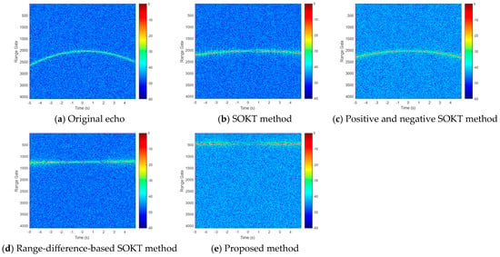
Figure 7.
The envelope of the target echo versus the observation time before and after SOKT methods.
After the compensation, the long-time coherent integration results from the conventional and proposed methods are shown in Figure 8a,b, respectively. Since there are still some high-order expansion terms present in the conventional method, the remaining signal phase would cause invalid compensation during the two-dimensional match filtering, even leakage into other adjacent channels. On the other hand, the expansion in our method prompts more accuracy, allowing the match filtering operation to better align with the desired target echo, thus ultimately achieving a long-time coherent integration more effectively. To continue, noncoherent integration between different frames and adjacent channels is performed as a suboptimal solution in terms of integration gain.
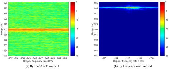
Figure 8.
The long-time coherent integration results.
Now, we turn to the aerial moving target detection period. In this period, we first take the corrected envelope of the target echo in the range domain and project it into X-Y-Z 3D space within the individual radar. Then, we perform multiradar target detection on the fused image. The 3D image is shown in Figure 9a, and its three principal cuts at the target location in the X-Y plane, X-Z plane, and Y-Z plane are displayed in Figure 9b, Figure 9c, and Figure 9d, respectively. The intersection pixels of K isorange rings are in the exact positions where the potential target lies. The integration gain of each pixel is determined by the number of participating radars. Thus, more radar beams covering the target position leads to higher integration gain. Similar to TOA target localization, one can locate aerial moving targets using multiple satellite radars. Likewise, the stated localization accuracy here is tightly correlated with the geometry diversity between the target and radars, especially for observing angle differences from different radars. To validate this, Figure 9b reveals a much better visualization for multiradar fusion compared to Figure 9c,d.
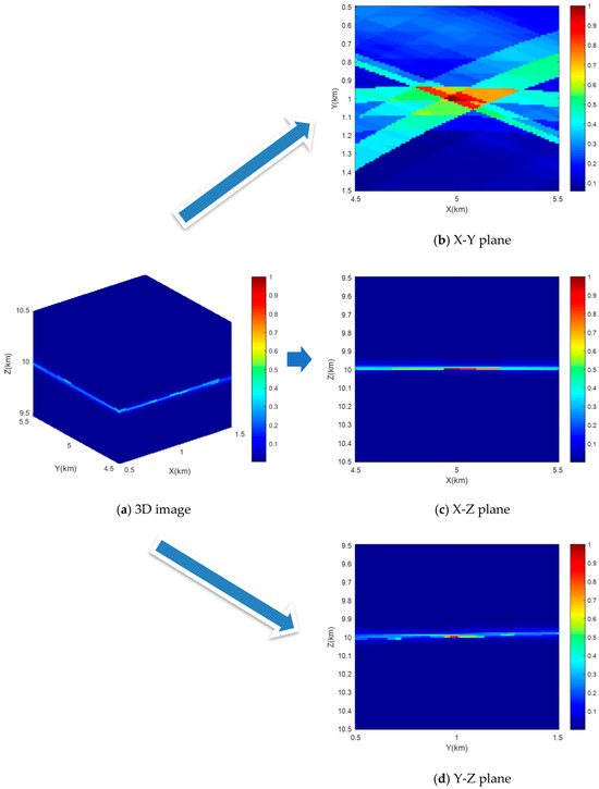
Figure 9.
The multiradar data fusion result.
4.3. Evaluation of Contrast-Enhanced Target Detection Method via Multiradar Data Fusion
Next, we apply our proposed approach to the fused 3D image in two consecutive stages. This helps us to improve the contrast ratio between the target and clutter background. In the first stage, the weighting function takes into account that all radars involved share a similar target DFR, resulting in the introduction of multiple equal DFR curves to locate the target, as well as the isorange rings. Thus, it enables us to concentrate more on the target of interest rather than the strongly isolated clutter patches, which would otherwise lead to false alarms. In the second stage, a smooth filter is considered to reduce irrelevant details and emphasize dominant target pixels in the 3D image. Following this, the 3D image is provided in Figure 10a, and the three principal cuts of the weighted fused image, corresponding to the X-Y plane, X-Z plane, and Y-Z plane, are depicted in Figure 10b, Figure 10c, and Figure 10d, respectively. This demonstrates that the image contrast in Figure 10 is enhanced to a great extent after the two-stage weighting operation, compared to those principal cuts in Figure 9, profiting from the DFR merit and image reweighting. Afterwards, we can detect potential aerial moving targets in the weighted 3D image.
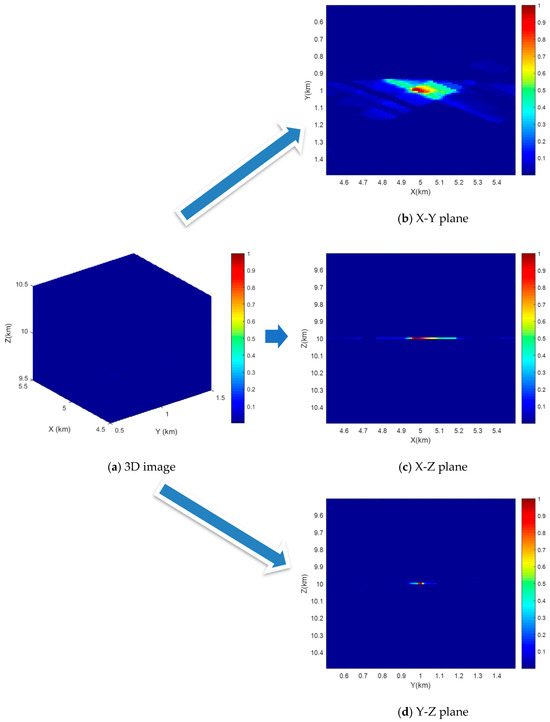
Figure 10.
The two-stage image weighting result.
After enhancing the image contrast, we detect potential targets in 3D space. The 3D scatter plots under the monostatic radar case, the multistatic radar case, and the two-stage weighting multistatic radar case are shown in Figure 11a, Figure 11b, and Figure 11c, respectively. Furthermore, we present the three principal cuts of these scatter plots in Figure 11d–l, where each row stands for different principal cuts, and each column gives rise to a different case. Compared to the monostatic case, multistatic detection takes advantage of observing the target from distinguished angles. The pixels of the target position among radars can be noncoherently integrated, and the target is at the intersection area of equal geometric curves. Hence, it ameliorates the target detection ability and increases target localization accuracy. On this basis, the proposed detection method further enhances image contrast and refines the detection region, resulting in better detection and localization performance.
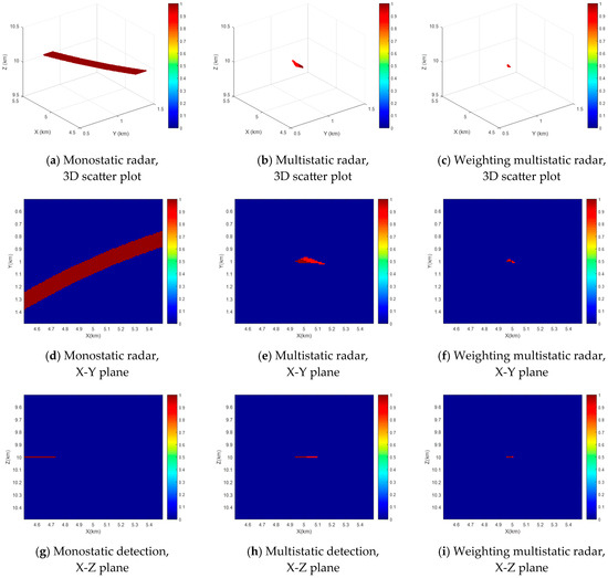

Figure 11.
The detection results under three different cases.
Moreover, the multi-target case is also considered. The two targets are located at [5e3, 1e3, 10.25e3]Tm, and [5.25e3, 0.75e3, 10e3]Tm in 3D space. The 3D scatter plots of this case under the monostatic radar case, the multistatic radar case, and the two-stage weighting multistatic radar case are shown in Figure 12a, Figure 12b, and Figure 12c, respectively. The two targets are isolated so that the pixels of the two target positions can be independently noncoherently integrated. The results indicate that the proposed method is also applicable for multi-target detection.

Figure 12.
The multi-target detection results under three different cases.
Finally, the evaluation of the detection performance of our proposed two-stage weighting technique is completed. Assume the false alarm probability and the Monte Carlo trial . In Figure 13, we compare the detection performances among monostatic radar, multistatic radar, and weighting multistatic radar. The cyan and black pentagram markers indicate the theoretical performances of monostatic and multistatic cases, respectively. In contrast, the blue and gray dashed lines represent the simulation results of those two cases. However, the simulation result of our weighting multistatic case is only provided using a red solid line, since calculating the theoretical detection probability is not practical, as mentioned previously. Profiting from the enhanced image contrast, we conclude that the weighted multistatic detection outperforms the original detection appreciably.
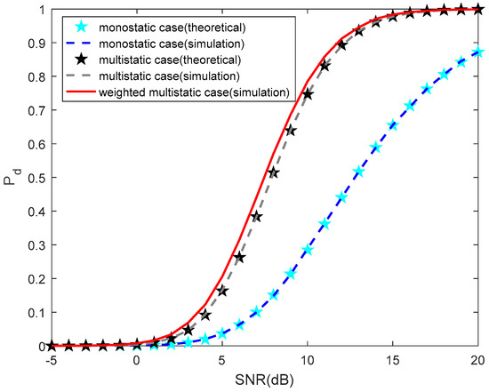
Figure 13.
The detection probability versus SNRs.
5. Discussions
In this manuscript, a contrast-enhanced approach for aerial moving target detection with distributed satellites is developed. This work addresses the problem of detecting aerial moving targets with distributed satellites, where the satellite radars operate in a self-transmitting and self-receiving mode, unlike monostatic radar. The proposed scheme is mainly divided into the following two periods.
- The integration period: The observation period is further divided into several frames, with the employment of coherent integration inside the frame and noncoherent integration among the frames. Since applying Taylor-series expansion to range difference is more accurate than to the target range itself, we develop a range-difference-based positive and negative second-order KT (SOKT) method to improve target motion compensation.
- The detection period: A contrast-enhanced method is proposed to detect aerial moving targets via DFR variance weighting function and smooth spatial filtering weighting function, where the first function is used to extract prominent areas based on equal target DFRs, whereas the second function aims to refine potential detection areas to improve detection efficiency.
6. Conclusions
Multistatic radar has the superiority of providing multiple independent perspectives against the variation of the target RCS, thus promoting target detection ability. For multistatic radar, signal integration over a long-time observation within individual radars is implemented first, followed by multiradar data fusion to detect potential targets. Unlike some existing methods, we alternatively apply the positive and negative SOKT method to the range difference instead of instantaneous range, during the integration period, to make the correction more accurate. In the detection period, two weighting functions, namely the multiradar DFR variance function and image smoothing spatial filter function, are developed to enlarge image contrast to enhance target detection. Additionally, the study also addresses the DFR grid size criterion to balance the separation between clutter and targets of interest and the data fusion among target echoes. The simulation results confirm that our proposed method can improve aerial moving target detection performance. The detection procedure refines the detection area, thus relieving the computational complexity. Future works should explore how we can manage radar resources to optimize multitarget detection in an active DRN.
Author Contributions
Conceptualization, Y.L. and H.S.; methodology, Y.L. and J.C.; software, J.C.; validation, W.W. and A.C.; formal analysis, C.D.; investigation, A.C. and C.D.; resources, Y.L. and Y.W.; data curation, Y.L.; writing—original draft preparation, Y.L. and J.C.; writing—review and editing, Y.L. and J.C.; visualization, Y.L. and H.S.; supervision, A.C. and C.D.; project administration, J.C.; funding acquisition, Y.L. and W.W. All authors have read and agreed to the published version of the manuscript.
Funding
This work was supported in part by the National Natural Science Foundation of China under grant number 62107033, National Key Laboratory Foundation under Grant 2023-JCJQ-LB-007, and Sustainedly Supported Foundation by National Key Laboratory of Science and Technology on Space Microwave under Grant HTKJ2024KL504001. The authors are grateful to the University of Electronic Science and Technology of China for supporting this research.
Data Availability Statement
The raw data supporting the conclusions of this article will be made available by the authors on request.
Acknowledgments
The authors are grateful to the associate editor and anonymous reviewers for their insightful comments and suggestions.
Conflicts of Interest
The authors declare no conflicts of interest.
References
- Koch, V.; Westphal, R. New approach to a multistatic passive radar sensor for air/space defense. IEEE Aerosp. Electron. Syst. Mag. 1995, 10, 24–32. [Google Scholar] [CrossRef]
- Ulander, L.M.H. Theoretical Considerations of Bi- and Multistatic SAR; Swedish Defence Research Agency: Stockholm, Sweden, 2004; pp. 1–24. [Google Scholar]
- Zeng, T.; Ao, D.; Hu, C.; Zhang, T.; Liu, F.; Tian, W.; Lin, K. Multiangle BSAR imaging based on beidou-2 navigation satellite system: Experiments and preliminary results. IEEE Trans. Geosci. Remote Sens. 2015, 53, 5760–5773. [Google Scholar] [CrossRef]
- Chen, J.; Huang, P.; Xia, X.G.; Chen, J.; Sun, Y.; Liu, X.; Liao, G. Multichannel signal modeling and AMTI performance analysis for distributed space-based radar systems. IEEE Trans. Geosci. Remote Sens. 2022, 60, 5117724. [Google Scholar] [CrossRef]
- Zhao, H.Y.; Zhang, Z.J.; Liu, J.; Zhou, S.; Zheng, J.; Liu, W. Target detection based on F-test in passive multistatic radar. Digit. Signal Process. 2018, 79, 1–8. [Google Scholar] [CrossRef]
- Liu, C.; Chen, W. Sparse self-calibration imaging via iterative MAP in FM-based distributed passive radar. IEEE Geosci. Remote Sens. Lett. 2013, 10, 538–542. [Google Scholar] [CrossRef]
- Hu, Y.; Yi, J.; Cheng, F.; Wan, X.; Hu, S. 3-D target tracking for distributed heterogeneous 2-D–3-D passive radar network. IEEE Sens. J. 2023, 23, 29502–29512. [Google Scholar] [CrossRef]
- Gao, Y.; Li, H.; Himed, B. Joint transmit and receive beamforming for hybrid active–passive radar. IEEE Signal Process. Lett. 2017, 24, 779–783. [Google Scholar] [CrossRef]
- Fang, Y.; Zhu, S.; Liao, B.; Li, X.; Liao, G. Target localization with bistatic MIMO and FDA-MIMO dual-mode radar. IEEE Trans. Aerosp. Electron. Syst. 2024, 60, 952–964. [Google Scholar] [CrossRef]
- McLaughlin, D.J.; Knapp, E.A.; Wang, Y.; Chandrasekar, V. Distributed weather radar using X-band active arrays. In Proceedings of the 2007 IEEE Radar Conference, Waltham, MA, USA, 17–20 April 2007; pp. 23–27. [Google Scholar]
- Kong, Y.K.; Cho, B.L. Ambiguity-free Doppler centroid estimation technique for airborne SAR using the radon transform. IEEE Trans. Geosci. Remote Sens. 2005, 43, 715–721. [Google Scholar] [CrossRef]
- Carlson, B.D.; Evans, E.D.; Wilson, S.L. Search radar detection and track with the Hough transform, Part I: System concept. IEEE Trans. Aerosp. Electron. Syst. 1994, 30, 102–108. [Google Scholar] [CrossRef]
- Perry, R.P.; DiPietro, R.C.; Fante, R.L. SAR imaging of moving targets. IEEE Trans. Aerosp. Electron. Syst. 1999, 35, 188–200. [Google Scholar] [CrossRef]
- Huang, P.H.; Liao, G.S.; Yang, Z. Long-time coherent integration for weak maneuvering target detection and high-order motion parameter estimation based on keystone transform. IEEE Trans. Signal Process. 2016, 64, 4013–4026. [Google Scholar] [CrossRef]
- Zhan, M.; Zhao, C.; Qin, K.; Huang, P.; Fang, M.; Zhao, C. Subaperture keystone transform matched filtering algorithm and its application for air moving target detection in an SBEWR system. IEEE J. Sel. Top. Appl. Earth Obs. Remote Sens. 2023, 16, 2262–2274. [Google Scholar] [CrossRef]
- Xu, J.; Yu, J.; Peng, Y.N.; Xia, X.G. Radon-Fourier transform for radar target detection, I: Generalized Doppler filter bank. IEEE Trans. Aerosp. Electron. Syst. 2011, 47, 1186–1202. [Google Scholar] [CrossRef]
- Xu, J.; Yu, J.; Peng, Y.N.; Xia, X.G. Radon-Fourier transform for radar target detection, II: Blind speed sidelobe suppression. IEEE Trans. Aerosp. Electron. Syst. 2011, 47, 2473–2489. [Google Scholar] [CrossRef]
- Rao, X.; Zhong, T.; Tao, H.; Xie, J.; Su, J. Improved axis rotation MTD algorithm and its analysis. Multidimens. Syst. Signal Process. 2019, 30, 885–902. [Google Scholar] [CrossRef]
- Fu, M.; Zhang, Y.; Wu, R.; Deng, Z.; Zhang, Y.; Xiong, X. Fast range and motion parameters estimation for maneuvering targets using time-reversal process. IEEE Trans. Aerosp. Electron. Syst. 2019, 55, 3190–3206. [Google Scholar] [CrossRef]
- Tenney, R.R.; Sandell, N.R. Detection with distributed sensors. IEEE Trans. Aerosp. Electron. Syst. 1981, 17, 501–510. [Google Scholar] [CrossRef]
- Blum, R.S. Necessary conditions for optimum distributed sensor detectors under the Neyman–Pearson criterion. IEEE Trans. Inf. Theory 1996, 42, 990–994. [Google Scholar] [CrossRef]
- Yan, Q.; Blum, R.S. Distributed signal detection under the Neyman-Pearson criterion. IEEE Trans. Inf. Theory 2001, 47, 1368–1377. [Google Scholar] [CrossRef]
- Viswanathan, R.; Varshney, P.K. Distributed detection with multiple sensors: Part I-fundamentals. Proc. IEEE 1997, 85, 54–63. [Google Scholar] [CrossRef]
- Ferrari, G.Z.; Pagliari, R. Decentralized binary detection with noisy communication links. IEEE Trans. Aerosp. Electron. Syst. 2006, 42, 1554–1563. [Google Scholar] [CrossRef]
- Aziz, A.M. A soft-decision fusion approach for multiple-sensor distributed binary detection systems. IEEE Trans. Aerosp. Electron. Syst. 2011, 47, 2208–2216. [Google Scholar] [CrossRef]
- Aziz, A.M. A new adaptive decentralized soft decision combining rule for distributed sensor systems with data fusion. Inf. Sci. 2014, 256, 197–210. [Google Scholar] [CrossRef]
- Yang, Y.; Su, H.; Hu, Q.; Zhou, S.; Huang, J. Centralized adaptive CFAR detection with registration errors in multistatic radar. IEEE Trans. Aerosp. Electron. Syst. 2018, 54, 2370–2382. [Google Scholar] [CrossRef]
- Hack, D.E.; Patton, L.K.; Himed, B.; Saville, M.A. Centralized passive MIMO radar detection without direct-path reference signals. IEEE Trans. Signal Process. 2014, 62, 3013–3023. [Google Scholar]
- Fishler, E.; Haimovich, A.; Blum, R.; Cimini, L.; Chizhik, D.; Valenzuela, R. Spatial diversity in radars-models and detection performance. IEEE Trans. Signal Process. 2006, 54, 823–838. [Google Scholar] [CrossRef]
- He, Q.; Lehmann, N.H.; Blum, R.S.; Haimovich, A.M. MIMO radar moving target detection in homogeneous clutter. IEEE Trans. Aerosp. Electron. Syst. 2010, 46, 1290–1301. [Google Scholar] [CrossRef]
- Wang, P.; Li, H.; Himed, B. Moving target detection using distributed MIMO radar in clutter with nonhomogeneous power. IEEE Trans. Signal Process. 2011, 59, 4809–4820. [Google Scholar] [CrossRef]
- Chong, C.Y.; Pascal, F.; Ovarlez, J.-P.; Lesturgie, M. MIMO radar detection in non-Gaussian and heterogeneous clutter. IEEE J. Sel. Top. Signal Process. 2010, 4, 115–126. [Google Scholar] [CrossRef]
- Chen, P.; Zheng, L.; Wang, X.; Li, H.; Wu, L. Moving target detection using colocated MIMO radar on multiple distributed moving platforms. IEEE Trans. Signal Process. 2017, 65, 4670–4683. [Google Scholar] [CrossRef]
- Duarte, M.; Hu, Y.-H. Distance based decision fusion in a distributed wireless sensor network. In Proceedings of the 2nd International Conference on Information Processing in Sensor Networks, Palo Alto, CA, USA, 22–23 April 2003; pp. 392–404. [Google Scholar]
- Marchan-Hernandez, J.F.; Valencia, E.; Rodriguez-Alvarez, N.; Ramos-Perez, I.; Bosch-Lluis, X.; Camps, A.; Eugenio, F.; Marcello, J. Sea-state determination using GNSS-R data. IEEE Geosci. Remote Sens. Lett. 2010, 7, 621–625. [Google Scholar] [CrossRef]
- Santi, F.; Bucciarelli, M.; Pastina, D.; Antoniou, M.; Cherniakov, M. Spatial resolution improvement in GNSS-based SAR using multistatic acquisitions and feature extraction. IEEE Trans. Geosci. Remote Sens. 2016, 54, 6217–6231. [Google Scholar] [CrossRef]
- Ramirez, J.; Krolik, J.L. Synthetic aperture processing for passive co-prime linear sensor arrays. Digit. Signal Process. 2017, 61, 62–75. [Google Scholar] [CrossRef]
- Suberviola, I.; Mayordomo, I.; Mendizabal, J. Experimental results of air target detection with a GPS forward-scattering radar. Remote Sens. Lett. 2012, 9, 47–51. [Google Scholar] [CrossRef]
- Ma, H.; Antoniou, M.; Cherniakov, M.; Pastina, D.; Santi, F.; Pieralice, F.; Bucciarelli, M. Maritime target detection using GNSS-based radar: Experimental proof of concept. In Proceedings of the 2017 IEEE Radar Conference (RadarConf), Seattle, WA, USA, 8–12 May 2017; Volume 9, pp. 0464–0469. [Google Scholar]
- Pastina, D.; Santi, F.; Pieralice, F.; Bucciarelli, M.; Ma, H.; Tzagkas, D.; Antoniou, M.; Cherniakov, M. Maritime moving target long time integration for GNSS-based passive bistatic radar. IEEE Trans. Aerosp. Electron. Syst. 2018, 54, 3060–3083. [Google Scholar] [CrossRef]
- Santi, F.; Pieralice, F.; Pastina, D. Joint detection and localization of vessels at sea with a GNSS-based multistatic radar. IEEE Trans. Geosci. Remote Sens. 2019, 57, 5894–5913. [Google Scholar] [CrossRef]
- Li, Z.; Huang, C.; Sun, Z.; An, H.; Wu, J.; Yang, J. BeiDou-based passive multistatic radar maritime moving target detection technique via spacetime hybrid integration processing. IEEE Trans. Geosci. Remote Sens. 2022, 60, 5802313. [Google Scholar]
- Nan, J.; Wang, J.; Feng, D.; Kang, N.X.; Huang, X.T. SAR imaging method for moving target with azimuth missing data. IEEE J. Sel. Top. Appl. Earth Observ. Remote Sens. 2022, 15, 7100–7113. [Google Scholar]
- Nan, J.; Feng, D.; Wang, J.; Zhu, J.H.; Huang, X.T. Along-track swarm SAR: Echo modeling and sub-aperture collaboration imaging based on sparse constraints. IEEE J. Sel. Top. Appl. Earth Observ. Remote Sens. 2023, 16, 5602–5617. [Google Scholar]
- Duan, C.; Li, Y.; Wang, W.; Li, J. LEO-based satellite constellation for moving target detection. Remote Sens. 2022, 14, 403. [Google Scholar] [CrossRef]
Disclaimer/Publisher’s Note: The statements, opinions and data contained in all publications are solely those of the individual author(s) and contributor(s) and not of MDPI and/or the editor(s). MDPI and/or the editor(s) disclaim responsibility for any injury to people or property resulting from any ideas, methods, instructions or products referred to in the content. |
© 2025 by the authors. Licensee MDPI, Basel, Switzerland. This article is an open access article distributed under the terms and conditions of the Creative Commons Attribution (CC BY) license (https://creativecommons.org/licenses/by/4.0/).